

Page 1

Pulse 125 ARF
Assembly Manual
Specications
Wingspan ............................................................... 76.0 in (193 cm)
Length.................................................................... 62.5 in (159 cm)
Wing Area ..................................................1050 sq in (68.0 sq dm)
Weight .......................................................... 8.2–9.5 lb (3.7–4.3 kg)
Engine Size ........................... .61–1.20 2-stroke; .90–1.25 4-stroke
Motor Size ...............................90–110 brushless outrunner Motor
Radio .........4-channels or more w/5 servos (4 w/electric option)
Page 2
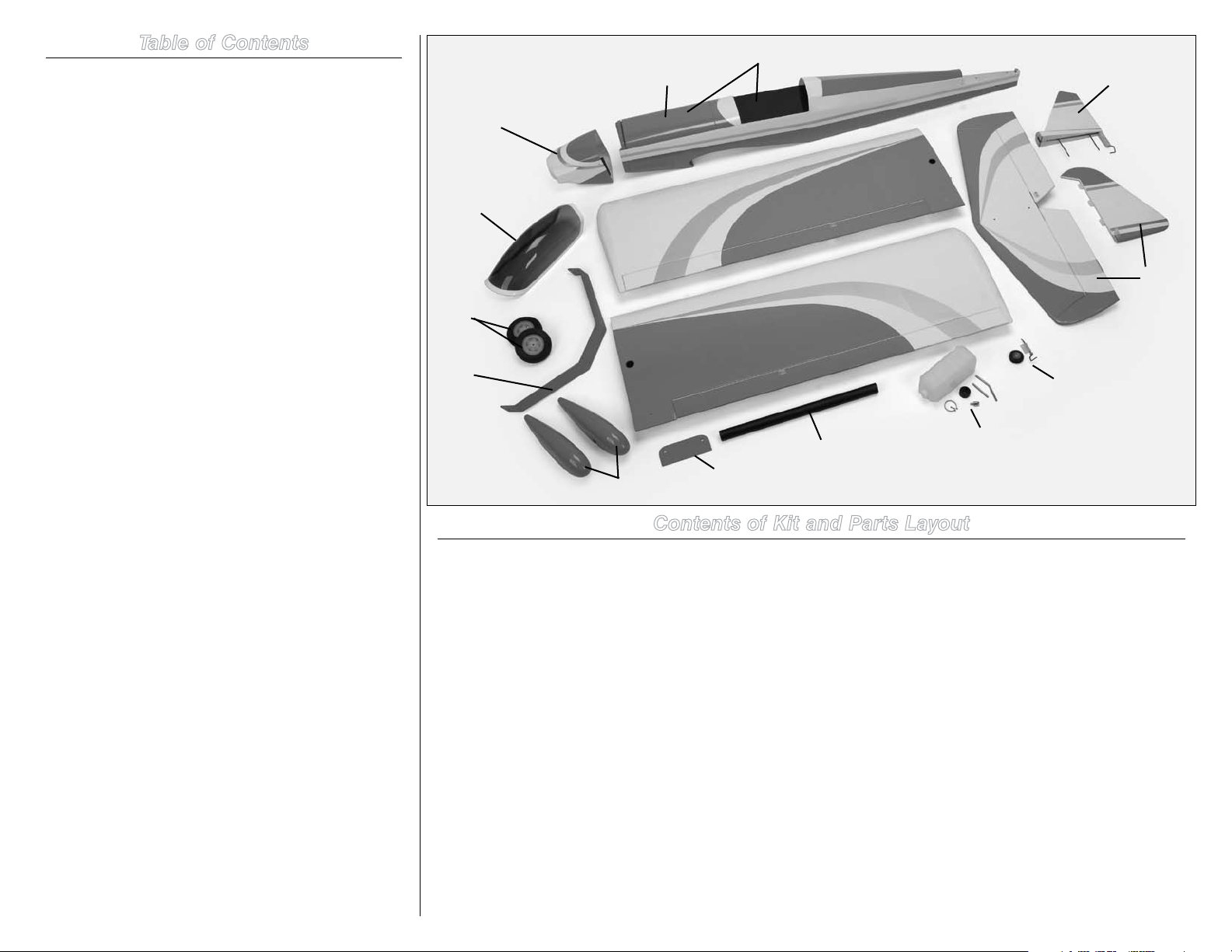
Table of Contents
Contents of Kit and Parts Layout ......................................2
Included Parts Listing .......................................................3
Using the Manual ..............................................................4
Important Information Regarding Warranty Information ..4
UltraCote® Covering Colors .............................................4
Before Starting Assembly .................................................4
Transmitter Requirements.................................................4
Radio Equipment Requirements .......................................4
Recommended Setup–2-Stroke Glow ...............................4
Recommended Setup–4-Stroke Glow ...............................4
Recommended Setup–4-Stroke Gas .................................4
Recommended Setup–Electric Power (EP) .......................4
Field Equipment Required .................................................4
Optional Field Equipment ..................................................4
Additional Required Tools .................................................5
Additional Required Adhesives .........................................5
FS One® ...........................................................................5
Rudder and Fin Preparation ..............................................5
Tail Installation ..................................................................7
Radio Installation ..............................................................8
Aileron Servo Installation ................................................11
Landing Gear and Wheel Installation ..............................13
Four-Stroke Engine Installation .......................................15
Two-Stroke Engine Installation .......................................19
Fuel Tank Installation ......................................................23
Cowling and Spinner Installation - Four-Stroke Engine ..25
Cowling and Spinner Installation - Two-Stroke Engine ...27
Electric Motor Installation ...............................................29
Cowling and Spinner Installation - Electric Motor...........31
Final Assembly ................................................................32
Center of Gravity .............................................................34
Control Throws ...............................................................34
Flight Preparations ..........................................................35
Safety Do’s and Don’ts for Pilots ....................................35
Daily Flight Checks ..........................................................35
Age Requirements ..........................................................36
Safety, Precautions and Warnings ..................................36
Warranty Information ......................................................36
CE Compliance Information for the European Union ......37
2009 Official Academy of
Model Aeronautics Safety Code ................................38
Engine Mounting Template .............................................39
1
2
7
6
11
8
10
3
14
Contents of Kit and Parts Layout
Replacement Parts
1. HAN517001 Fuselage with Hatch
2. HAN517002 Fuselage Hatch
3. HAN517003 Left Wing Panel
4. HAN517004 Right Wing Panel
5. HAN517005 Horizontal and Vertical Stabilizer
6. HAN517006 Canopy
7. HAN517007 Cowl
8. HAN517008 Landing Gear, with Axles
9. HAN517010 Wing Tube
10. HAN517011 Wheelpants (2)
11. HAN517012 Main Wheels
12. HAN517015 Fuel Tank
13. HAN517017 Tailwheel Assembly
14. HAN517018 Wing Bolt Plate
5
4
13
12
9
5
Items not shown:
HAN517009 Landing Gear Axles
HAN517013 Engine Mount
HAN517014 EP Motor Mount
HAN517016 Hardware Package
HAN517019 Wing Mounting Nylon Bolts
2 Hangar 9 Pulse 125 ARF Assembly Manual
Page 3

Included Parts Listing
LANDING GEAR & COWL MOUNT HARDWARE
3.35-inch rubber wheel 2
1.35-inch rubber tail wheel 1
2mm wheel collar with setscrew 1
4mm wheel collar with setscrew 4
5mm x 44mm steel axles with nut 2
3mm x 15mm socket head cap screw 5 Landing gear
3mm x 10mm socket head cap screw 8 Cowl/wheel pants
3mm washer 13
PUSHROD
1
3
/4-inch (2mm) pushrod with steel clevis and nut 2 Aileron
7
26
/8-inch (2mm) pushrod with clevis and nut 1 Rudder
1
28
/4-inch (2mm) pushrod with clevis and nut 1 Elevator
5
21
/8-inch (2mm) pushrod with clevis and nut 1 Throttle
FUEL TANK
16 oz (470cc) fuel tank 1
3mm x 50mm aluminum tube 2
3mm x 70mm aluminum tube 1
Rubber stopper 1
Self-tapping screw 1
Silicon tube 1
Nylon stopper piece 2
10mm x 10mm x 110mm tank brace 1
WING AND TAIL HARDWARE
5/16 x 2-inch dowel with aluminum sleeve 2
6mm x 40mm nylon wing bolt 2 Wing bolts
3mm washer 2 Tail attachment
3mm nylon lock nut 2 Tail attachment
MOTOR MOUNT
Nylon motor mount 2
75mm aluminum standoff 4
4mm x 25mm socket head cap screw 8 Mount to firewall/EP mounts
4mm blind nut 4 Mount to firewall
4mm washer 4 Mount to firewall
4mm x 25mm socket head cap screws 4 Engine to mount
4mm locknut 4 Engine to mount
4mm washer 8 Engine to mount
CONTROL HORNS
Nylon clevis 4
2mm x 20mm machine screw 8
Brass pushrod connector with backplate 1 Throttle
Silicon clevis keeper 4
Plywood firewall template 1
3Hangar 9 Pulse 125 ARF Assembly Manual
Page 4
Using the Manual
This manual is divided into sections to help make assembly
easier to understand, and to provide breaks between each
major section. In addition, check boxes have been placed
next to each step to keep track of each step completed.
Steps with a single box () are performed once, while steps
with two boxes () indicate that the step will require
repeating, such as for a right or left wing panel, two servos,
etc. Remember to take your time and follow the directions.
Important Information
Regarding Warranty Information
Please read our Warranty and Liability Limitations section on
Page 36 before building this product. If you as the purchaser
or user are not prepared to accept the liability associated
with the use of this Product, you are advised to return this
Product immediately in new and unused condition to the
place of purchase.
UltraCote® Covering Colors
• Orange HANU877
• Silver HANU881
• White HANU870
Before Starting Assembly
Before beginning the assembly of your model, remove
each part from its bag for inspection. Closely inspect the
fuselage, wing panels, rudder and stabilizer for damage. If
you find any damaged or missing parts, contact the place of
purchase.
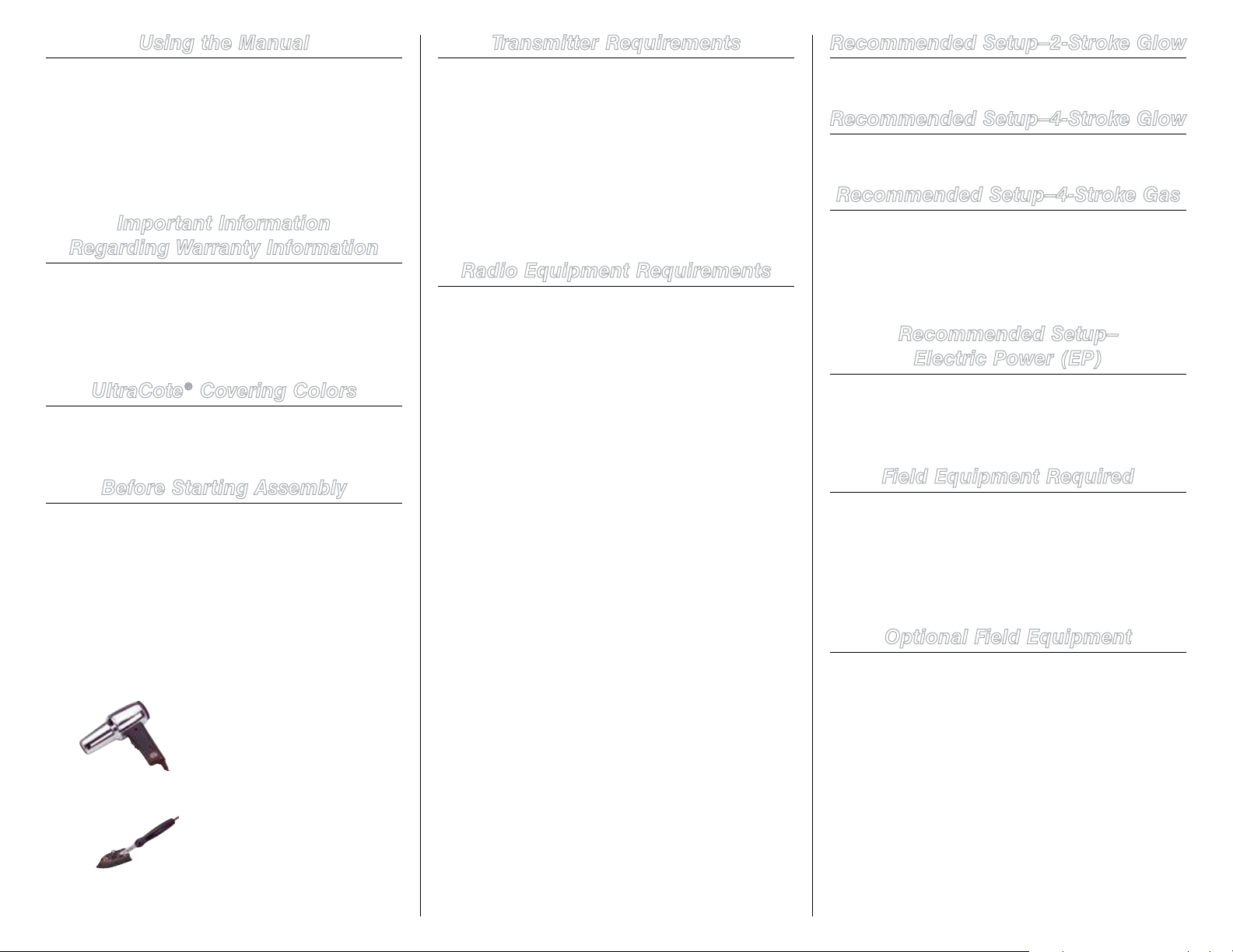
If you find any wrinkles in the covering, use a heat gun or
covering iron to remove them. Use caution while working
around areas where the colors overlap to prevent separating
the colors.
HAN100 – Heat Gun
HAN150 – Covering Glove
Transmitter Requirements
The Pulse 125 ARF requires a minimum of a 4-channel radio
to operate the functions of your aircraft. We suggest the
following radio systems available through Horizon Hobby or
your local hobby distributor.
Spektrum DX6i with receiver SPM6600
Spektrum DX7 with receiver SPM2710
JR Systems X9303 2.4GHz with receiver JRP2915
Radio Equipment Requirements
The following items are recommended when installing the
receiver in your aircraft:
AR7000 7-Channel Receiver SPM6070
DS821 Digital Sport Servo (5) JRPS821
(Note: Only 4 servos required for EP version)
9-inch Servo Extension (2) JRPA097
3-inch Servo Extension (2) JSP98100 or
Y-harness JSP98020
JR Switch, Chargeswitch JRPA004
Receiver battery, 6-volt, 2700mAh JRPB5008
Aileron option 1:
DS821 Servo (2) (No mixing required)
• Y-harness (plugged into receiver)
• 9-inch extension (connected to servo) (2)
Aileron option 2:
DS821 Servo (2) (requires mixing of aileron servos)
• 3-inch extension (plugged into receiver) (2)
• 9-inch extension (connected to servo) (2)
Rudder: DS821 Servo
Elevator: DS821 Servo
Throttle: DS821 Servo (Not required for electric version)
Recommended Setup–2-Stroke Glow
• Evolution
• Evolution Propeller 15 x 6 (EVO15060)
®
120NX Engine (EVOE1200)
Recommended Setup–4-Stroke Glow
™
• Saito
1.25 AAC (SAIE125A or SAIE125AGK)
• Evolution Propeller 16 x 6 (EVO16060)
Recommended Setup–4-Stroke Gas
™
• Saito
FG20 (SAIEG20)
• Evolution Propeller 15 x 6 (EVO15060)
• Ignition Battery (JRPB5008)
• Ignition Switch (JRPA004)
• Evolution 2-stroke Oil (EVOX1001Q)
Recommended Setup–
Electric Power (EP)
®
• E-flite
• Phoenix HV-85 High Voltage ESC (CSEPHX85HV)
• Thunder Power 4S 3850–4500mAh Li-Po Battery Pack
• APC Propeller 16 x 12E (APC16012E)
Power 110 BL Outrunner Motor (EFLM4110A)
Field Equipment Required
• Fuel (15% recommended)
• Propeller
• Long Reach Glow Plug Wrench (HAN2510)
• Metered Glow Driver w/Ni-Cd & Charger (HAN7101)
• 2-Cycle Sport Plug (EVOGP1)
• Manual Fuel Pump (HAN118)
Optional Field Equipment
• Selfstick weights, 6 oz (HAN3626)
• PowerPro 12V Starter (HAN161)
• 12V 7Ah Sealed Battery (HAN102)
• Power Panel (HAN106)
• Blue Block After Run Oil Applicator (EVOX1001)
• Blue Blocker After Run Oil Refill (EVOX1002)
• Cleaner and towels
HAN101 – Sealing Iron
HAN141 – Sealing Iron Sock
4 Hangar 9 Pulse 125 ARF Assembly Manual
The Spektrum trademark is used with permission
of Bachmann Industries, Inc.
Page 5
Additional Required Tools
FS One®
Rudder and Fin Preparation
• Cardstock • Covering iron
• Double-sided tape • Drill
• Felt-tipped pen • Hobby scissors
• Low-tack tape • Medium grit sandpaper
• Mixing cup • Mixing stick
• Nut driver: 5.5mm • Paper towel
• Petroleum jelly • Flat file
• Pin drill • Pliers
• Rubbing alcohol • Side cutter
• Straight edge • Tapered reamer
• Phillips screwdriver: #1, #2 • T-pins
• Hobby knife with #11 blade
• Rotary tool with sanding drum
• Box or open end wrench: 10mm (2)
• Hex wrench or ball driver: 1.5mm, 2mm, 4mm
• Drill bit: 1/16-inch (1.5mm), 5/64-inch (2mm),
5/32-inch (4mm), 3/16-inch (5mm)
Additional Required Adhesives
• Canopy Glue (PAAPT56)
• Thin CA (PAAPT08)
• Threadlock (PAAPT42)
• 30-Minute Epoxy (HAN8002)
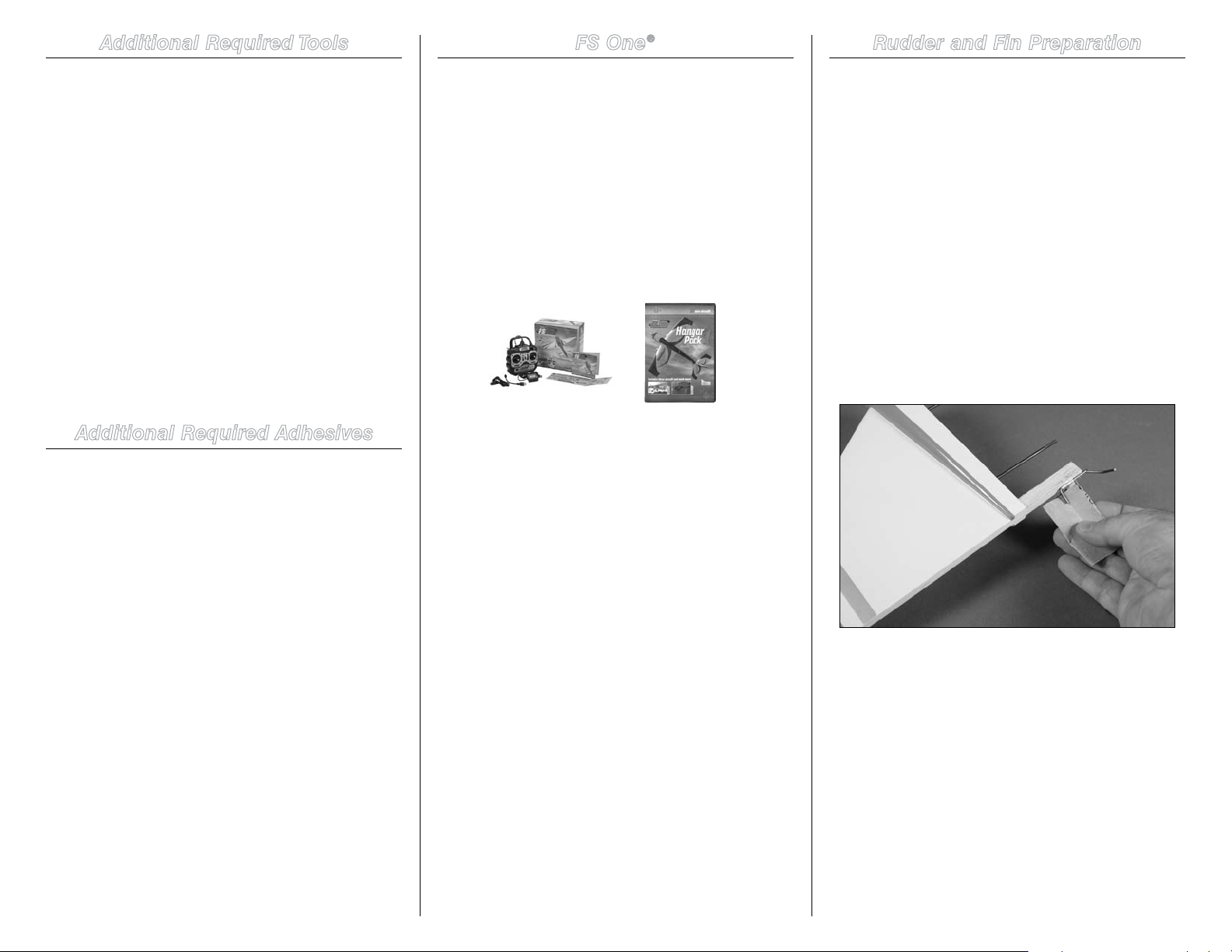
With FS One (HANS2000) you get more than photorealistic
fields, gorgeous skies and realistic-looking aircraft. You get
incredibly advanced aerodynamic modeling that simulates
every possible aspect of real-world flight.
The first Hangar Pack (HANS4010) will add even more
aircraft to FS One. This latest edition includes ten new planes
and helis from your favorite brands, including Hangar 9,
E-flite and Align. You’ll be able to fly aircraft that are only
available on FS One such as the T-REX, Blade CX2, Blade CP
Pro, Hangar 9 P-51 and F-22 PTS. And as always, with the
Hangar Pack, you still get all the same great features that
you did with the original aircraft.
HANS2008 HANS4010
Required Parts
Rudder Fin
Tail wheel bracket CA hinge (3)
Tools and Adhesives
T-pins Petroleum jelly
Hobby knife with #11 blade Thin CA
30-minute epoxy Mixing stick
Mixing cup Medium grit sandpaper
Rubbing alcohol Paper towel
Drill bit: 1/16-inch (1.5mm Pin drill
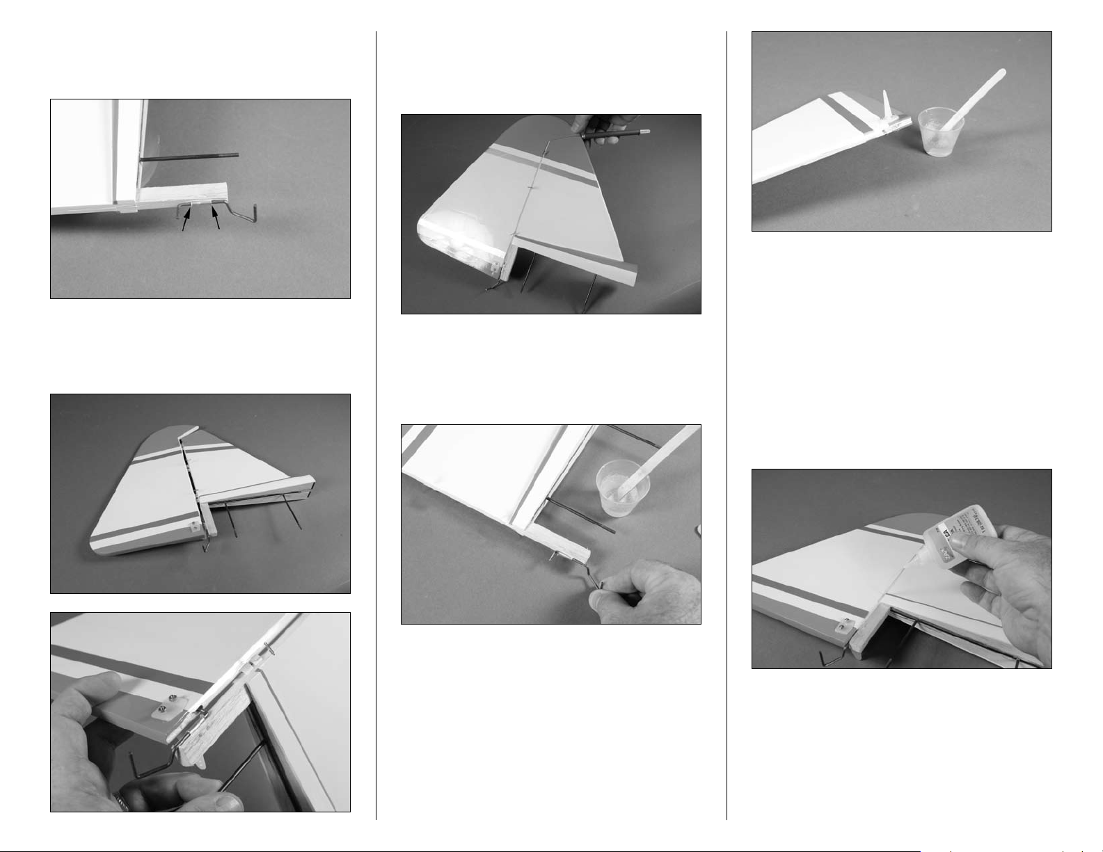
Step 1
Use medium grit sandpaper to roughen the tail gear wire.
This provides a better surface for the epoxy to adhere to.
5Hangar 9 Pulse 125 ARF Assembly Manual
Page 6
Step 2
Apply a small amount of petroleum jelly to the tail gear wire.
This will keep the epoxy from gluing the wire to the bracket.
Step 4
When fitting the rudder, make sure there is a sufficient gap
between the rudder and fin. Use a hobby knife to set the
correct spacing.
Note: Use a paper towel and rubbing alcohol to remove
any excess epoxy before it cures. Excess epoxy could
cause the rudder and fin to bind and increase the load
on the rudder servo.
Step 3
Test fit the rudder on the hinges. Make sure the tail gear fits
into the pre-drilled hole in the rudder.
Step 5
Mix a small amount of 30-minute epoxy. Apply the epoxy to
both the tail gear wire where it enters the rudder and to the
hole in the rudder.
Step 6
The rudder and fin can now be joined together. While the
epoxy cures, wick thin CA into each hinge. Apply the CA
to both sides of the hinge. Allow the CA to cure WITHOUT
using accelerator as this will not allow the CA to wick full
into the hinge. Continue once the CA and epoxy have both
cured.
6 Hangar 9 Pulse 125 ARF Assembly Manual
Page 7
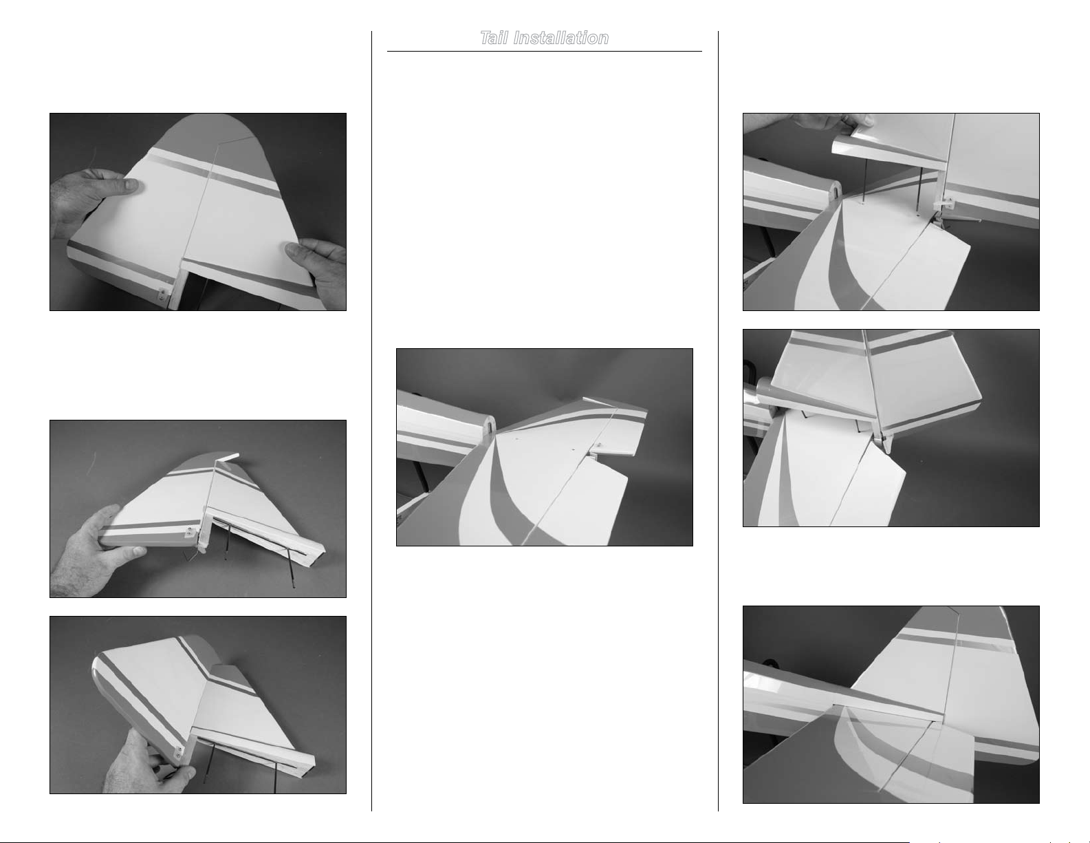
Step 7
Gently pull on the rudder and fin to make sure the hinges are
secure. If any of the hinges break loose, reapply CA to the
hinge.
Step 8
The last step is to break in the hinges. Move the rudder
through its range of movement a few times until it moves
freely.
Tail Installation
Required Parts
Fuselage Rudder/fin assembly
Elevator/stabilizer assembly 3mm washer (2)
3mm locknut (2)
Tools and Adhesives
Nut driver: 5.5mm Thin CA
Important: Check and break in the elevator hinges
before starting this section of the manual. Apply thin CA
to any loose hinges.
Step 1
Position the stabilizer on the stabilizer saddle at the rear of
the fuselage.
Step 2
Insert the threaded rods from the fin through the holes in the
stabilizer and into the holes in the fuselage. You will need to
deflect the rudder so the control horn can pass the elevator.
Step 3
When installed, the fin will fit tight against the stabilizer.
7Hangar 9 Pulse 125 ARF Assembly Manual
Page 8
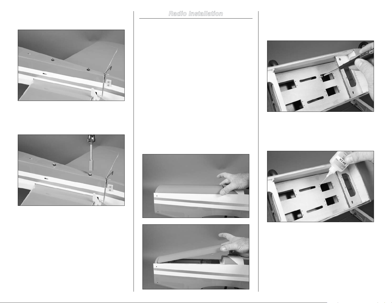
Step 4
Place two 3mm washers on the threaded rods.
Step 5
Thread two 3mm locknuts on the threaded rods. Use a
5.5mm nut driver to tighten the nuts.
Radio Installation
Required Parts
Fuselage Metal clevis (2)
2mm nut (2) Clevis retainer (2)
Servo with hardware (2) Switch harness
Receiver battery Receiver
1/4-inch (6mm) foam Y-harness
Elevator linkage wire, 27.5-inch (698mm)
Rudder linkage wire, 28.5-inch (724mm)
Tools and Adhesives
Phillips screwdriver: #1, #2
Side cutters Straight edge
Thin CA Pin drill
Drill bit: 5/64-inch (2mm)
Step 1
Slide the hatch on the fuselage forward to disengage the
magnets at the rear of the hatch. Lift the hatch up at the rear
and remove it from the fuselage.
Step 2
Use a #1 Phillips screwdriver to thread a servo mounting
screw into each of the holes in the radio tray. This will cut
the threads for the screws in preparation of the next step.
Step 3
Place 2–3 drops of thin CA in each hole to harden the
surrounding wood. This harder surface will make the screws
less likely to vibrate loose.
Important: Do not over-tighten the nuts and damage
the fuselage. The nuts only need to be tightened enough
so the stabilizer and fin are secure and do not move on
the fuselage.
8 Hangar 9 Pulse 125 ARF Assembly Manual
Page 9
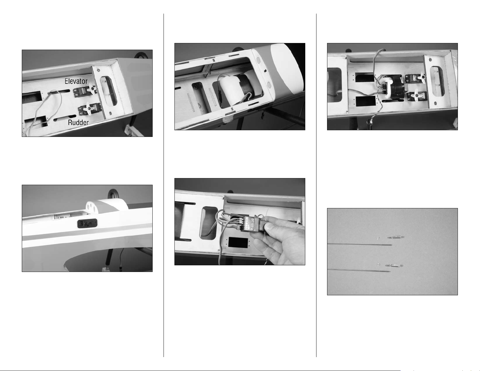
Step 4
After preparing the rudder and elevator servo with the
appropriate hardware, secure them in the radio tray using
the screws provided with the servos.
Step 5
Remove the covering from the side of the fuselage to mount
your particular switch. There are a few different locations, so
choose the correct one for your application.
Step 6
Wrap the receiver battery in foam and secure it in position
using a hook and loop strap (not included).
Step 7
Plug the rudder and elevator servo leads in the correct ports
of your receiver. Also plug the aileron Y-harness and lead
from the switch harness at this time.
Step 8
Wrap the receiver in foam and secure it in position as
shown.
Note: The remote receiver will be mounted later in
the manual. Its location will be determined by your
particular motor selection.
Step 9
Remove the clevises and nuts from the 27.5-inch (698mm)
and 28.5-inch (724mm) linkage wires. Set the hardware
aside so it doesn’t get lost.
9Hangar 9 Pulse 125 ARF Assembly Manual
Page 10
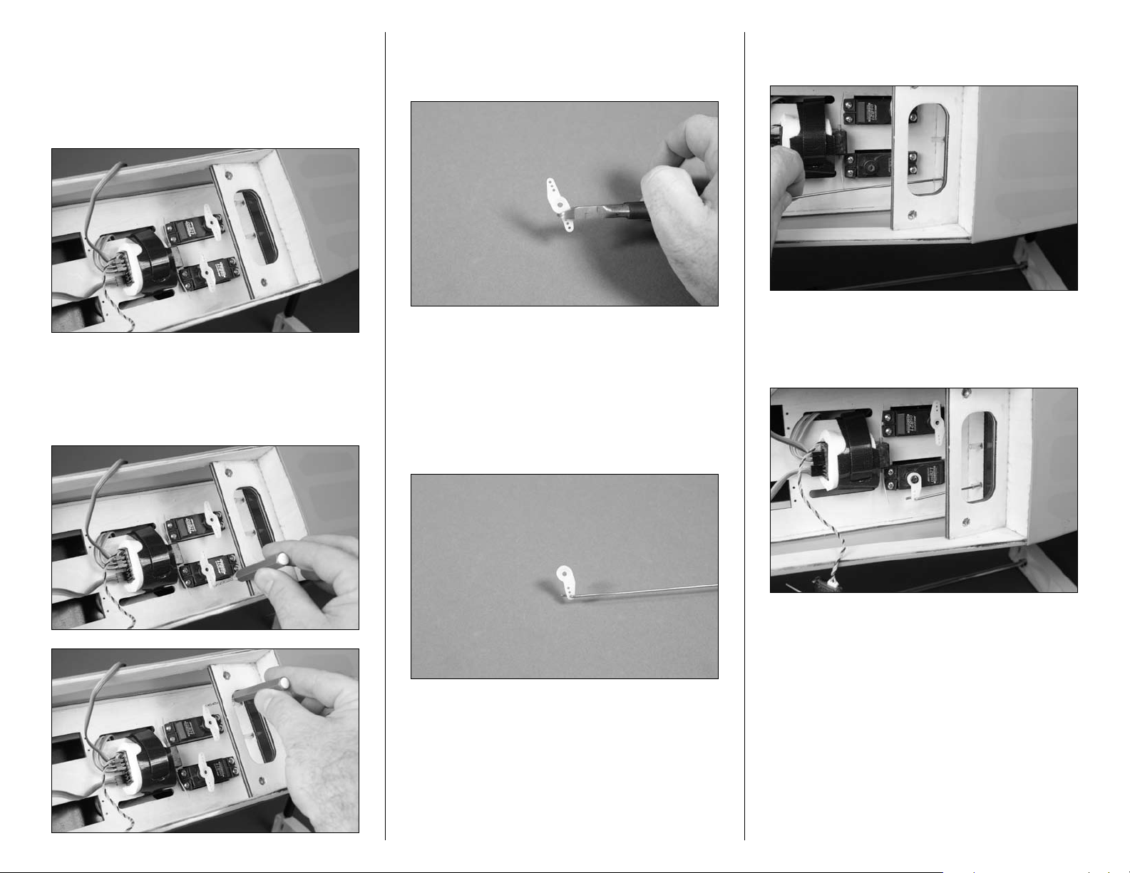
Step 10
Remove the stock servo horns from the servos. Center the
servos using the radio system. Use a 180-degree servo
horn on the servos. You may need to rotate the horns
180-degrees to get them to align perpendicular to the
servos.
Step 12
Remove the horns from the rudder servo and use side
cutters to trim the arm from the horn that will not be used.
Step 14
Slide the pushrod wire into the tube near the rudder servo.
Step 11
Use a pin drill and 5/64-inch (2mm) drill bit to enlarge the
holes that are 9/16-inch (15mm) from the center of the servo
horn for the pushrod wires.
Note: Removing the excess arm will help in preventing
interference between the arm and other components
inside the fuselage.
Step 13
Insert the Z-bend from the 281/2-inch (724mm) pushod in
the hole enlarged earlier.
Step 15
With the rudder servo still centered, secure the servo horn to
the rudder servo using the screw provided with the servo.
10 Hangar 9 Pulse 125 ARF Assembly Manual
Page 11
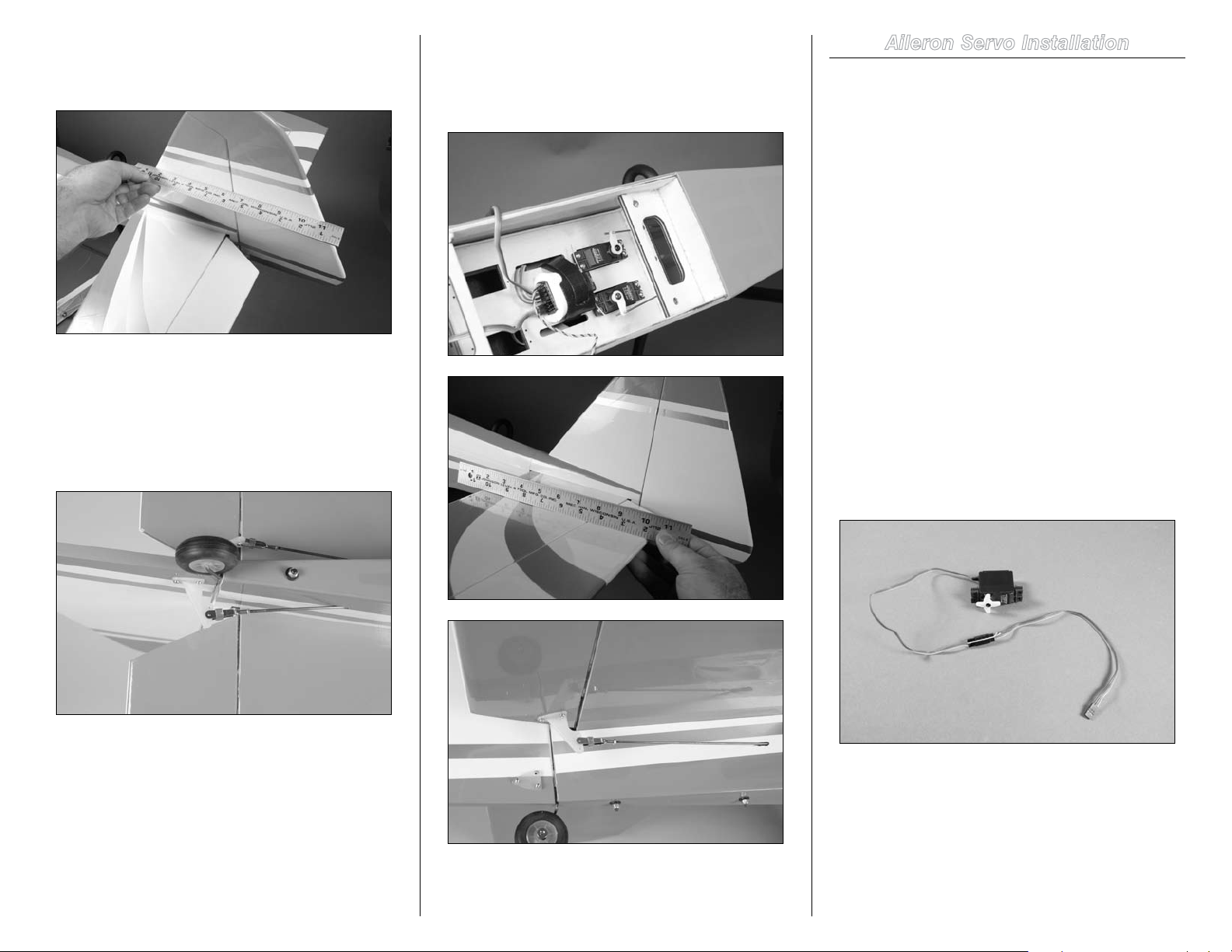
Step 16
Use a straight edge to make sure the rudder is aligned with
the fin.
Step 18
Repeat Steps 12 through 17 to install the 27.5-inch (698mm)
linkage wire for the elevator. Attach the clevis to the center
hold on the elevator control horn.
Aileron Servo Installation
Required Parts
Wing panel (right and left) Metal clevis (2)
Clevis retainer (2) 2mm nut (2)
Wing dowel (2) Servo with hardware (2)
9-inch (228mm) servo entension (2)
Aileron linkage wire, 3.5-inch (90mm) (2)
Tools and Adhesives
Thin CA Mixing cup
30-minute epoxy Mixing stick
Rubbing alcohol Paper towel
Phillips screwdriver: #1 Side cutters
Thin CA
Step 17
Slide a clevis retainer on the clevis. Thread the 2mm nut
and clevis back on the pushrod wire. Attach the clevis in the
center hole of the control horn. Tighten the nut against the
clevis, then slide the clevis retainer over the forks of the
clevis to keep it from popping loose in flight.
Important: Make sure to use threadlock on all metalto-metal fasteners.
Important: Check and break in the aileron hinges
before starting this section of the manual. Apply thin CA
to any loose hinges.
Step 1
Secure a 9-inch (228mm) servo extension to the aileron
servo.
11Hangar 9 Pulse 125 ARF Assembly Manual
Page 12
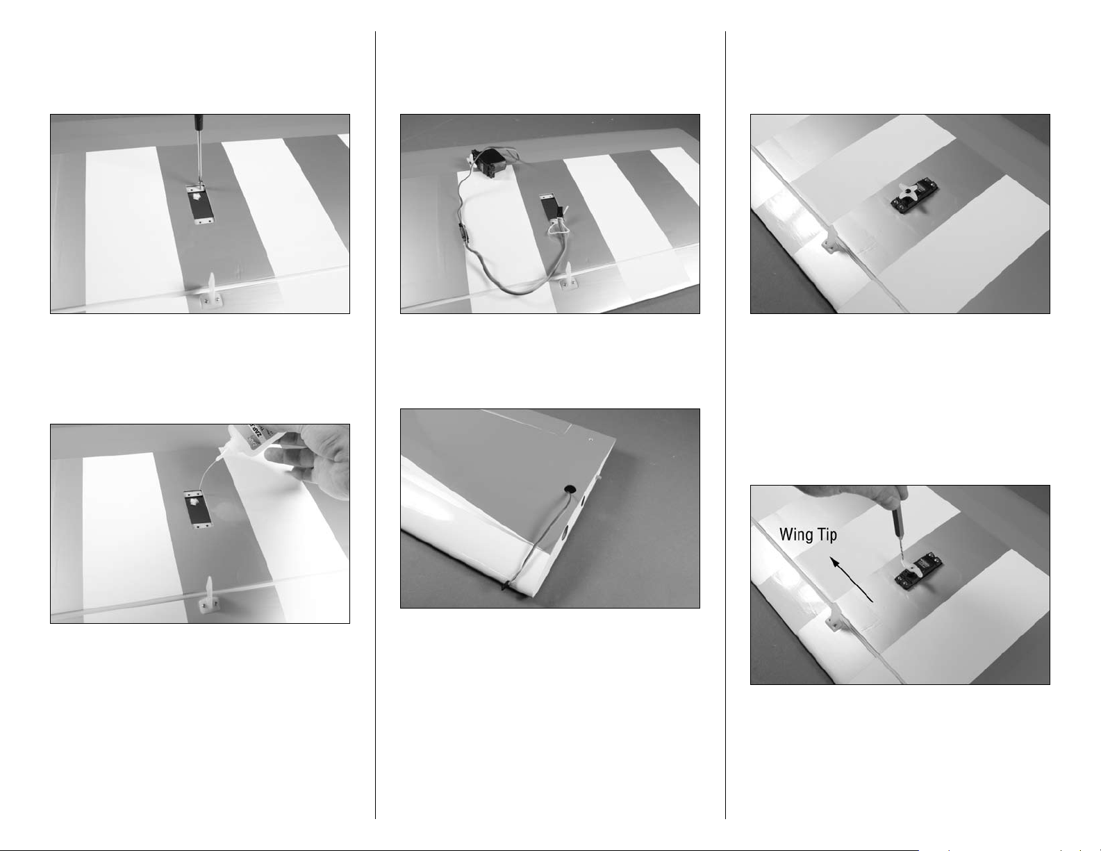
Step 2
Thread a servo mounting screw into each of the holes for
mounting the servo. This will cut the threads for the screws
in preparation of the next step.
Step 4
Remove the tape that secures the string inside the wing. Do
not remove the string from the wing. Tie the end around the
servo extension.
Step 6
Secure the servo in the wing using the screws included
with the servo. Make sure the output of the servo faces the
aileron.
Step 3
Place 2–3 drops of thin CA in each hole to harden the
surrounding wood. This harder surface will make the screws
less likely to vibrate loose.
Step 5
Use the string to pull the servo lead through the wing and
out the hole as shown.
Step 7
Remove the stock servo horns from the servo. Center the
servo using the radio system. Use a 180-degree servo horn
on the servo. You may need to rotate the horn 180-degrees
to get it to align parallel to the aileron hinge line. Use a pin
drill and 5/32-inch (2mm) drill bit to enlarge the hole that is
9/16-inch (15mm) from the center of the servo horn for the
pushrod wire.
12 Hangar 9 Pulse 125 ARF Assembly Manual
Page 13
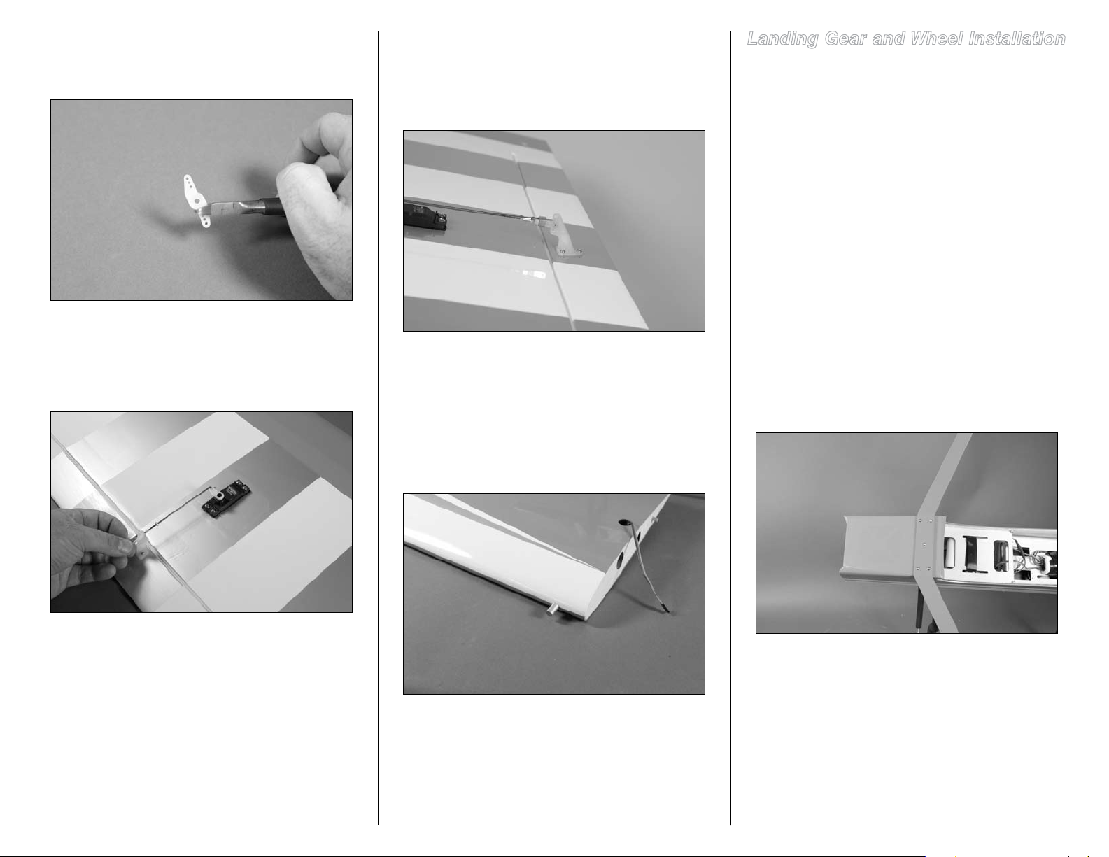
Step 8
Remove the horns from the aileron servo and use side
cutters to trim the arm from the horn that will not be used.
Step 10
Connect the clevis to the center hole in the aileron control
horn. Tighten the 2mm nut against the clevis, then slide the
clevis retainer over the forks of the clevis to keep it from
popping loose in flight.
Landing Gear and Wheel Installation
Required Parts
Fuselage Aluminum landing gear
Wheel axle with nut (2) Main wheel (2)
Tail wheel Wheel pant (right and left)
3mm x 8mm button head screw (4)
2mm wheel collar with setscrew
4mm wheel collar with setscrew (4)
3mm x 16mm button head screw (5)
Tools and Adhesives
Threadlock Flat file
Box or open end wrench: 10mm (2)
Hex wrench or ball driver: 1.5mm, 2mm
Step 9
Secure the servo horn to the servo using the screw removed
earlier. Insert the Z-bend in the 3.5-inch (90mm) pushrod
wire in the hole enlarged in the servo horn.
Important: Make sure to use threadlock on all metalto-metal fasteners.
Step 11
Use 30-minute epoxy to glue the wing dowel in the leading
edge of the wing. Remove any excess epoxy using a paper
towel soaked in rubbing alcohol.
Step 12
Repeat Steps 1 through 12 to prepare the opposite wing
panel.
Step 1
Attach the landing gear to the fuselage using five 3mm x
16mm button head screws. The gear will angle back on the
fuselage as shown in the image below. Make sure to use
threadlock on the screws so they don’t vibrate loose.
13Hangar 9 Pulse 125 ARF Assembly Manual
Page 14
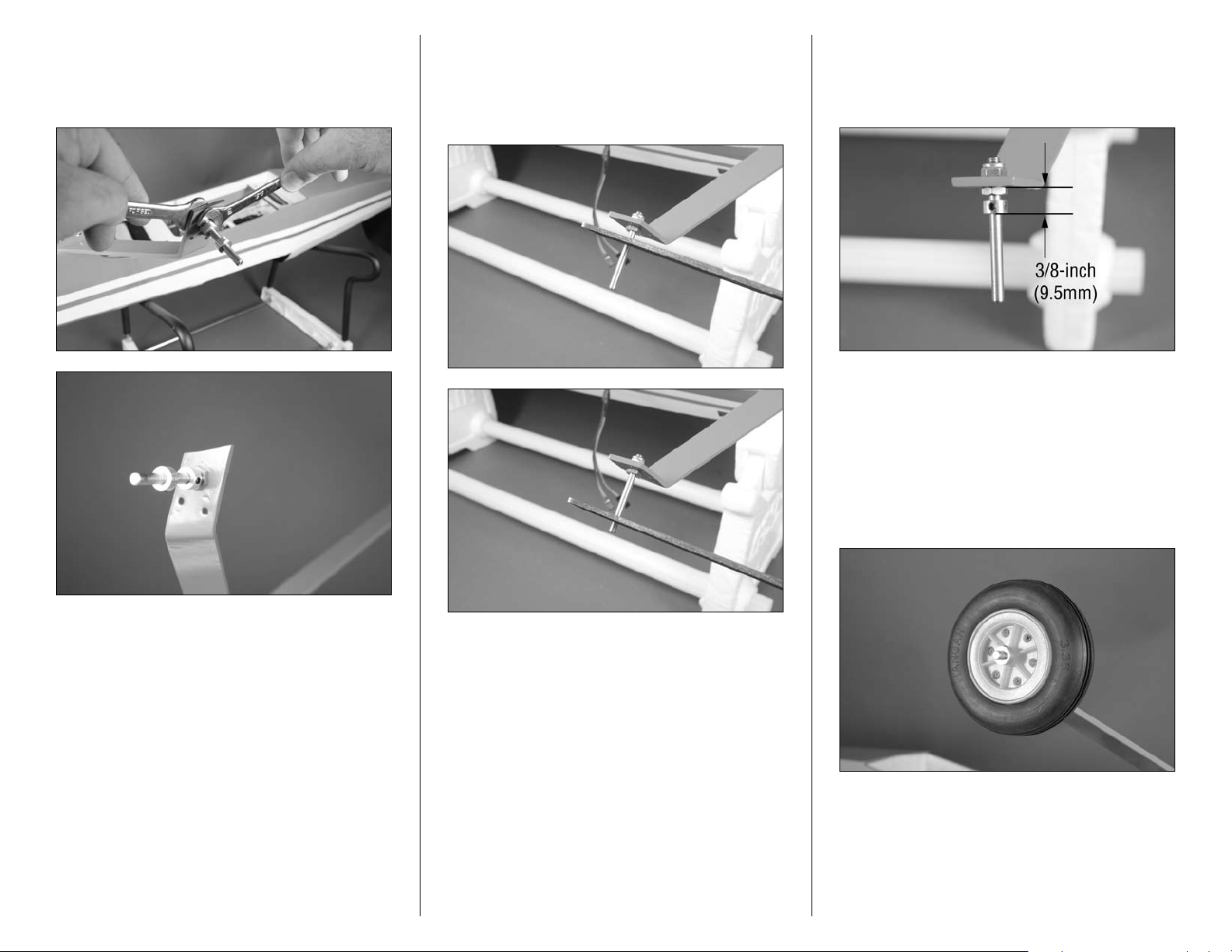
Step 2
Use two 10mm wrenches to install the wheel axle. Make sure
to align the nut vertically so the wheel pant will fit over the
nut.
Step 3
Remove the collars from the axle. Use the edge of a flat file
to make two flat areas on the bottom of the axle. This will
provide an area for the setscrew making the collars more
secure on the axle.
Step 4
Position one of the wheel collars 3/8-inch (9.5mm) from the
edge of the gear as shown. Tighten the setscrew to secure
the collar to the axle.
Note: Always use threadlock on metal-to-metal
fasteners to prevent them from vibrating loose.
Step 5
Place the wheel on the axle, then use another wheel collar
to secure the wheel. Make sure the collar is not too tight
against the wheel by making sure the wheel can rotate freely
on the axle.
Hint: Place a drop of machine oil on the axle so the
wheel will roll freely.
14 Hangar 9 Pulse 125 ARF Assembly Manual
Page 15
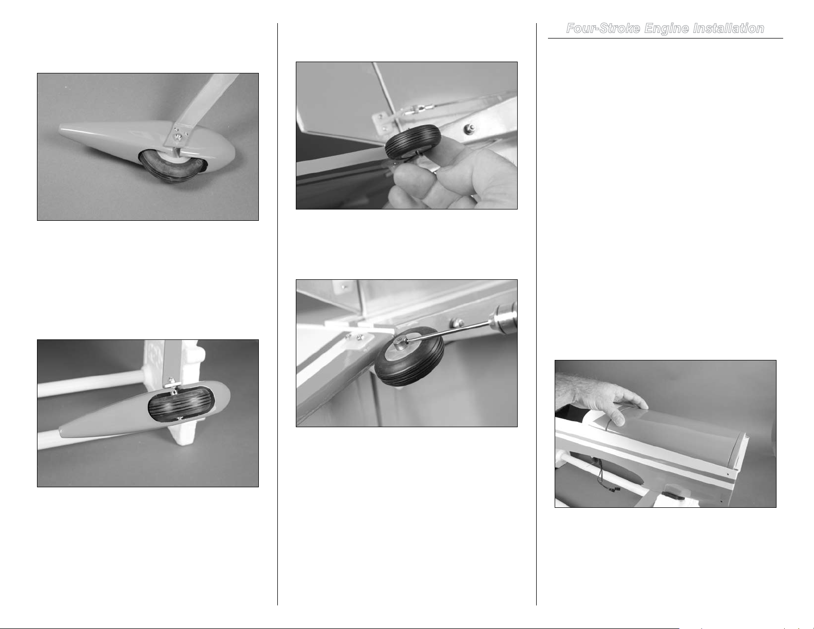
Step 6
Use two 3mm x 8mm button head screws to secure the
wheel pant on the landing gear.
Note: Always use threadlock on metal-to-metal
fasteners to prevent them from vibrating loose.
Step 7
Check to make sure the wheel is centered in the opening in
the bottom of the wheel pant. If not, loosen the wheel collars
and reposition the wheel.
Step 9
Slide the tail wheel on the tail gear wire.
Step 10
Use a 2mm wheel collar to keep the tail wheel on the tail
gear wire.
Four-Stroke Engine Installation
Required Parts
Fuselage 4mm washer (8)
4mm locknut (4)
Throttle pushrod with clevis
Brass pushrod connector with backplate
4mm x 25mm socket head bolt (8)
Engine mount rail (right and left)
Plywood engine mount template
Tools and Adhesives
Drill Low-tack tape
Pin drill Felt-tipped pen
Hobby knife with #11 blade
Rotary tool with sanding drum
Hex wrench or ball driver: 1.5mm, 4mm
Drill bit: 1/16-inch (1.5mm), 5/32-inch (4mm),
3/16-inch (5mm)
Step 1
Slide the hatch on the fuselage forward to disengage the
magnets at the rear of the hatch. Lift the hatch up at the rear
and remove it from the fuselage.
Step 8
Repeat Steps 2 through 7 to install the remaining wheel and
wheel pant.
Note: Always use threadlock on metal-to-metal
fasteners to prevent them from vibrating loose.
15Hangar 9 Pulse 125 ARF Assembly Manual
Page 16
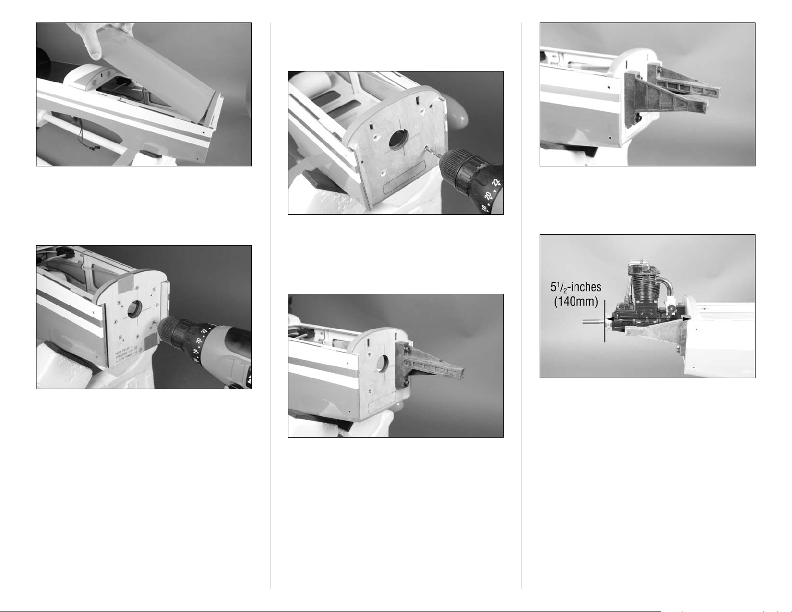
Step 3
Remove the template and use a 5/32-inch (4mm) drill bit to
enlarge the four holes drilled in the previous step.
Step 2
Use low-tack tape to attach the firewall template to the
firewall. Use a drill and 1/16-inch (1.5mm) drill bit to drill the
appropriate holes into the firewall.
Step 5
Position the engine on the mount so the front face of the
driver washer is 51/2-inches (140mm) forward of the firewall.
Step 4
Use four 4mm x 25mm socket head screws and four 4mm
washers to secure the nylon mounts to the firewall. Note the
positioning of the mounts as shown in the photos.
16 Hangar 9 Pulse 125 ARF Assembly Manual
Page 17
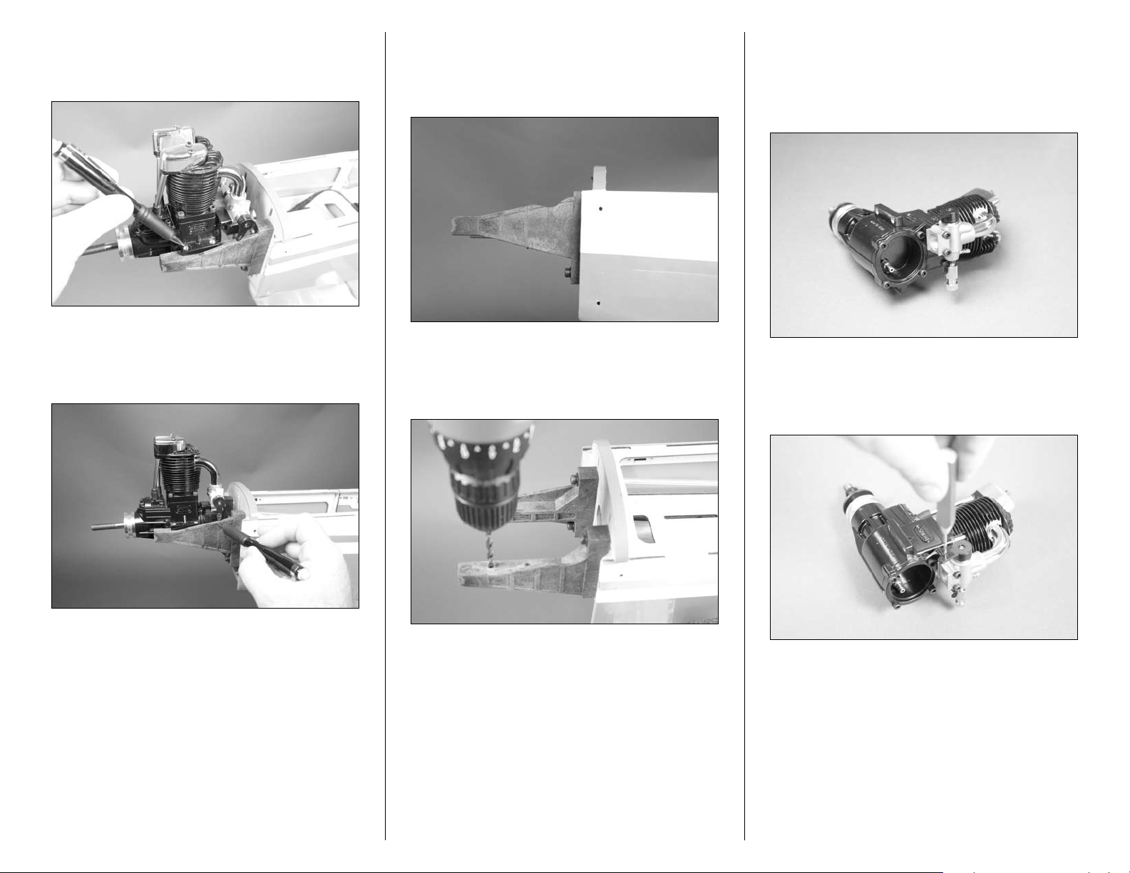
Step 6
Use a felt-tipped pen to mark the mount for the engine
mounting hardware.
Step 7
Use a felt-tipped pen to mark the mount if necessary so the
carburetor arm can move freely.
Step 8
Remove the engine from the mount. Use a rotary tool and
sanding drum to remove enough material from the mount so
the carburetor arm can move freely.
Step 9
Use a drill and a 5/32-inch (4mm) drill bit to drill the four
holes through the mount to secure the engine.
Step 10
Check the direction of the carburetor in relationship to the
engine. If it does not look like the position in the photo
below, follow the instructions provided with the engine to
reposition the carburetor.
Step 11
Use a pin drill and 1/16-inch (1.5mm) drill bit to enlarge the
center hole of the carburetor arm.
Hint: It is suggested to use a drill press to drill these
holes. This will guarantee they are aligned straight in
the mount.
17Hangar 9 Pulse 125 ARF Assembly Manual
Page 18
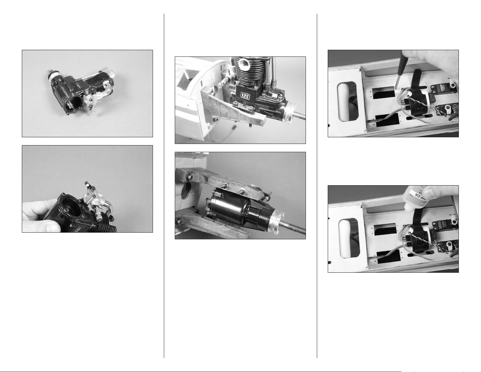
Step 12
Insert the brass pushrod connector in the hole. Use the
nylon backplate to secure the connector to the carburetor
arm.
Step 13
Secure the engine to the mount using four 4mm x 25mm
socket head screws, four 4mm washers and four 4mm nylon
locknuts. The washers will be on the bottom side of the
mount between the locknut and nylon mount.
Step 14
Thread a servo mounting screw into each of the holes in
the radio tray. This will cut the threads for the screws in
preparation of the next step.
Step 15
Place 2–3 drops of thin CA in each hole to harden the
surrounding wood. This harder surface will make the screws
less likely to vibrate loose.
18 Hangar 9 Pulse 125 ARF Assembly Manual
Page 19
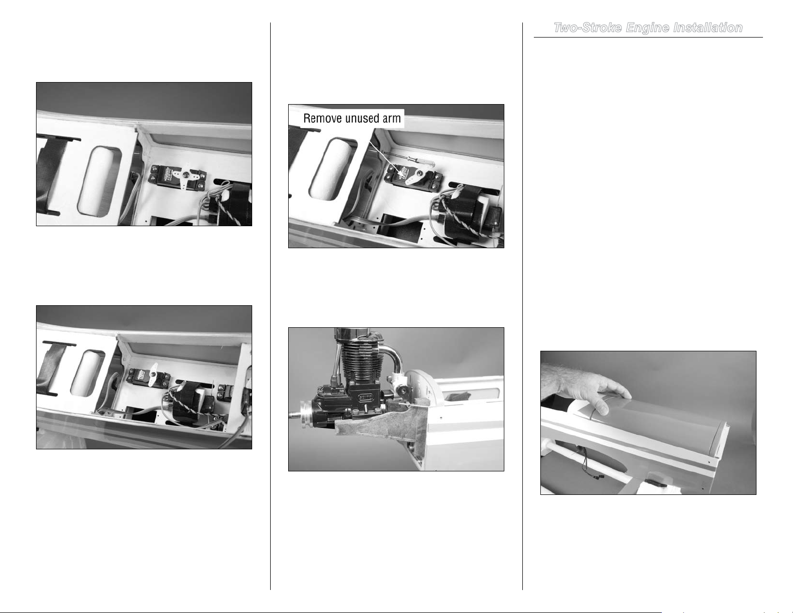
Step 16
After preparing the throttle servo with the appropriate
hardware, secure it in the radio tray using the screws
provided with the servo.
Step 17
Remove the servo horn provided with your servo. After using
the radio to center the servo, install a 180-degree servo horn
as shown in the image below.
Step 18
Connect the clevis from the throttle pushrod to the hole of
the throttle servo horn that is 9/16-inch (15mm) from the
center of the servo horn. Use the radio system to move the
throttle servo to the low-throttle position. Use side cutters to
remove any unused arms from the throttle servo.
Step 19
Tighten the setscrew in the pushrod connector to secure
the wire to the carburetor arm. Use side cutters to trim any
excess wire extending beyond the connector.
Two-Stroke Engine Installation
Required Parts
Fuselage 4mm washer (8)
4mm locknut (4)
Throttle pushrod with clevis
Brass pushrod connector with backplate
4mm x 25mm socket head bolt (8)
Engine mount rail (right and left)
Plywood engine mount template
Tools and Adhesives
Drill Low-tack tape
Pin drill Felt-tipped pen
Hobby knife with #11 blade
Rotary tool with sanding drum
Hex wrench or ball driver: 1.5mm, 4mm
Drill bit: 1/16-inch (1.5mm), 5/32-inch (4mm),
3/16-inch (5mm)
Step 1
Slide the hatch on the fuselage forward to disengage the
magnets at the rear of the hatch. Lift the hatch up at the rear
and remove it from the fuselage.
Note: Always use threadlock on metal-to-metal
fasteners to prevent them from vibrating loose.
19Hangar 9 Pulse 125 ARF Assembly Manual
Page 20
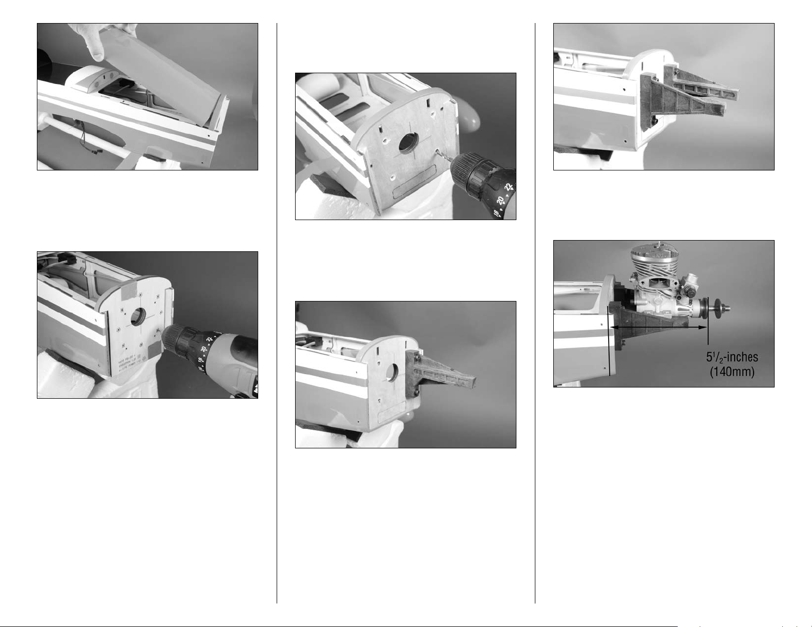
Step 3
Remove the template and use a 5/32-inch (4mm) drill bit to
enlarge the four holes drilled in the previous step.
Step 2
Use low-tack tape to attach the firewall template to the
firewall. Use a drill and 1/16-inch (1.5mm) drill bit to drill the
appropriate holes into the firewall.
Step 5
Position the engine on the mount so the front face of the
driver washer is 51/2-inches (140mm) forward of the firewall.
Step 4
Use four 4mm x 25mm socket head screws and four 4mm
washers to secure the nylon mounts to the firewall. Note the
positioning of the mounts as shown in the photos.
20 Hangar 9 Pulse 125 ARF Assembly Manual
Page 21
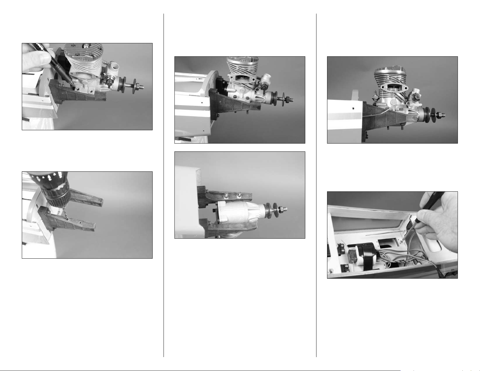
Step 6
Use a felt-tipped pen to mark the mount for the engine
mounting hardware.
Step 7
Use a drill and a 5/32-inch (4mm) drill bit to drill the four
holes through the mount to secure the engine.
Step 8
Secure the engine to the mount using four 4mm x 25mm
socket head screws, four 4mm washers and four 4mm nylon
locknuts. The washers will be on the bottom side of the
mount between the locknut and nylon mount.
Step 9
Slide the throttle pushrod in the pushrod tube. Bend the
pushrod so the clevis can be connected to the innermost
hole of the carburetor arm. Slide the clevis retainer over the
forks of the clevis so it won’t accidentally open in flight.
Step 10
Thread a servo mounting screw into each of the holes in
the radio tray. This will cut the threads for the screws in
preparation of the next step.
Hint: It is suggested to use a drill press to drill these
holes. This will guarantee they are aligned straight in
the mount.
21Hangar 9 Pulse 125 ARF Assembly Manual
Page 22
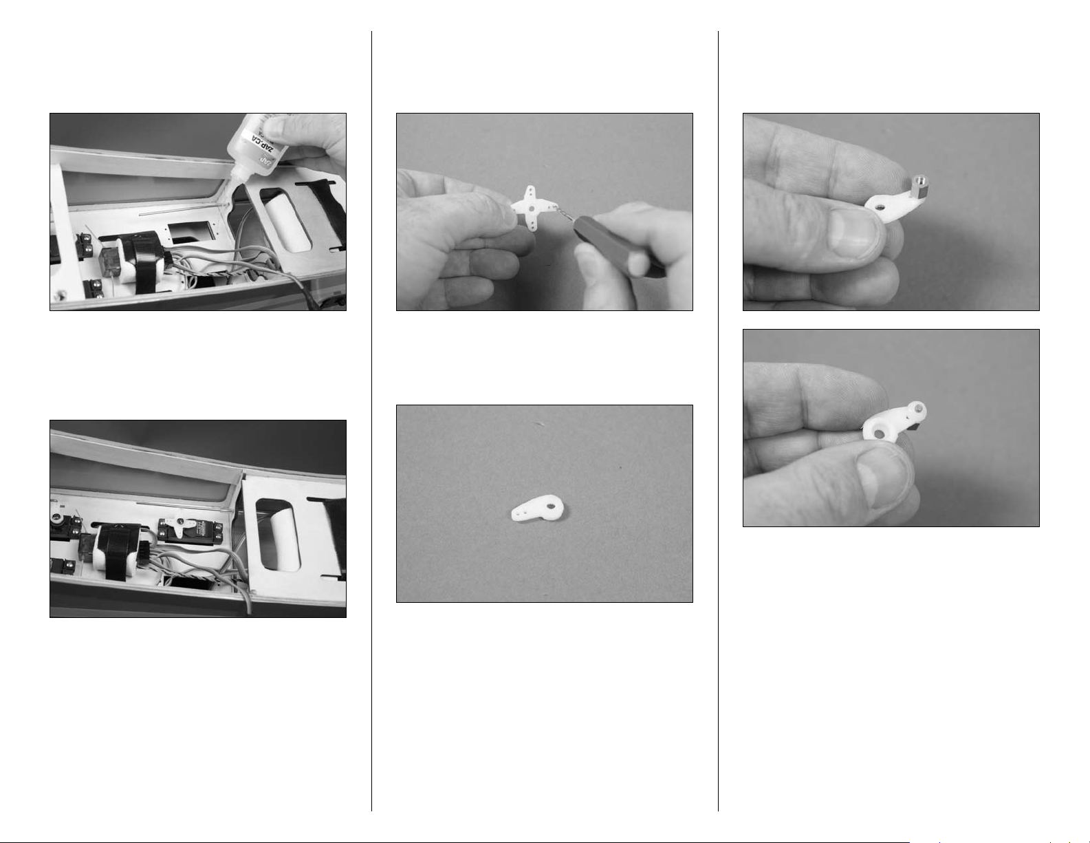
Step 11
Place 2–3 drops of thin CA in each hole to harden the
surrounding wood. This harder surface will make the screws
less likely to vibrate loose.
Step 13
Remove the servo horn from the servo. Use a pin drill and
5/64-inch (1.5mm) drill bit to enlarge the hole that is 1/2inch (13mm) from the center of the center of the horn.
Step 15
Insert the brass pushrod connector in the hole enlarged
previously. Use a connector backplate to secure the
connector to the servo horn.
Step 12
After preparing the throttle servo with the appropriate
hardware, secure it in the radio tray using the screws
provided with the servo.
Step 14
Use side cutters to remove any excess arms from the servo
horn so they don’t interfere with the operation of the throttle.
22 Hangar 9 Pulse 125 ARF Assembly Manual
Page 23
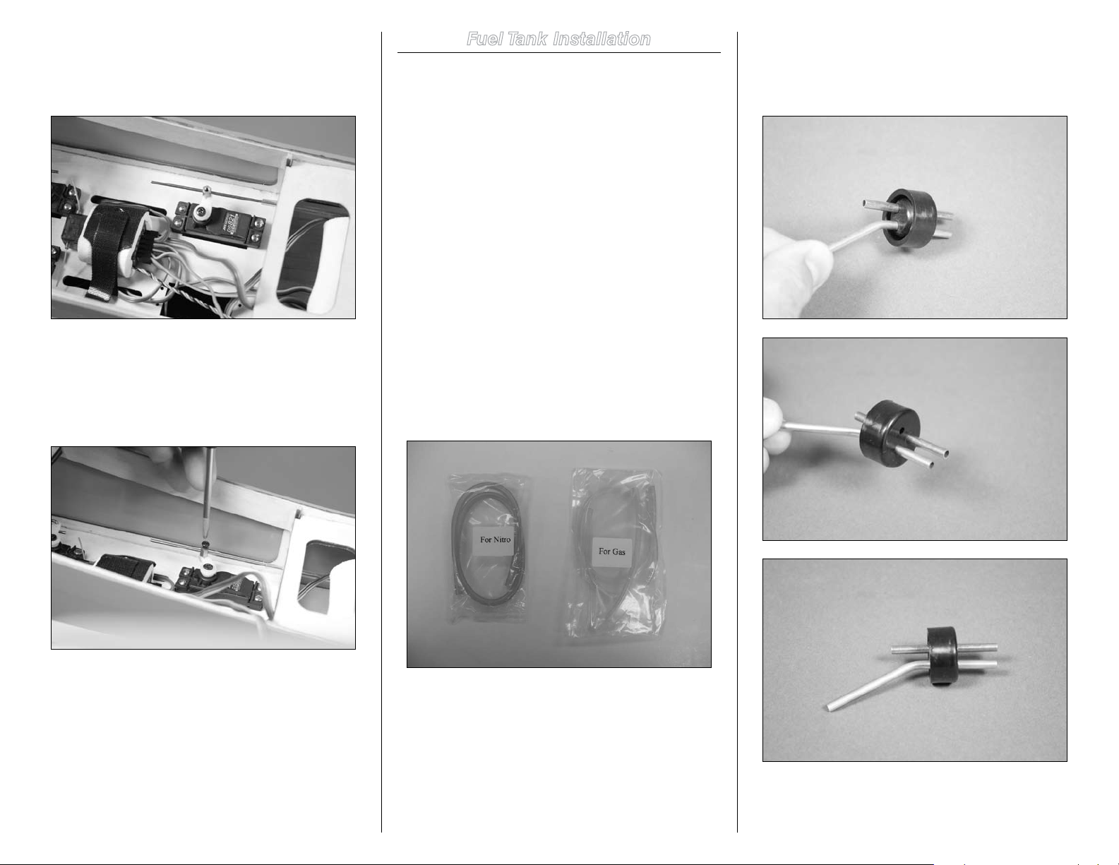
Step 16
Use the radio system to center the throttle servo. Install the
arm perpendicular to the servo centerline. This will provide
an equal amount of throw from low to high throttle.
Step 17
Tighten the setscrew in the pushrod connector to secure the
wire to the servo arm. Use side cutters to trim any excess
wire extending beyond the connector if it interferes with the
operation of the throttle or rudder servos.
Fuel Tank Installation
Required Parts
Fuselage Copper fuel tube (straight)
Copper fuel tube (bent) Fuel tank stopper
Steel clunk Clunk fuel line
Stopper clamp 2mm locknut
Nylon tie-wrap Fuel tubing (gas or nitro)
2mm x 12mm machine screw
1/4-inch (6mm) foam rubber
Tools and Adhesives
Phillips screwdriver: #1 Pliers
Side cutter Double-sided tape
Hobby knife with #11 blade
Important: Two types of fuel tubing have been
included for your model: One is for use with
nitromethane (pink) and one is for use with gasoline
(yellow). Before beginning the assembly of your fuel
tank, make sure you have selected the correct tubing for
the type of fuel you will be using.
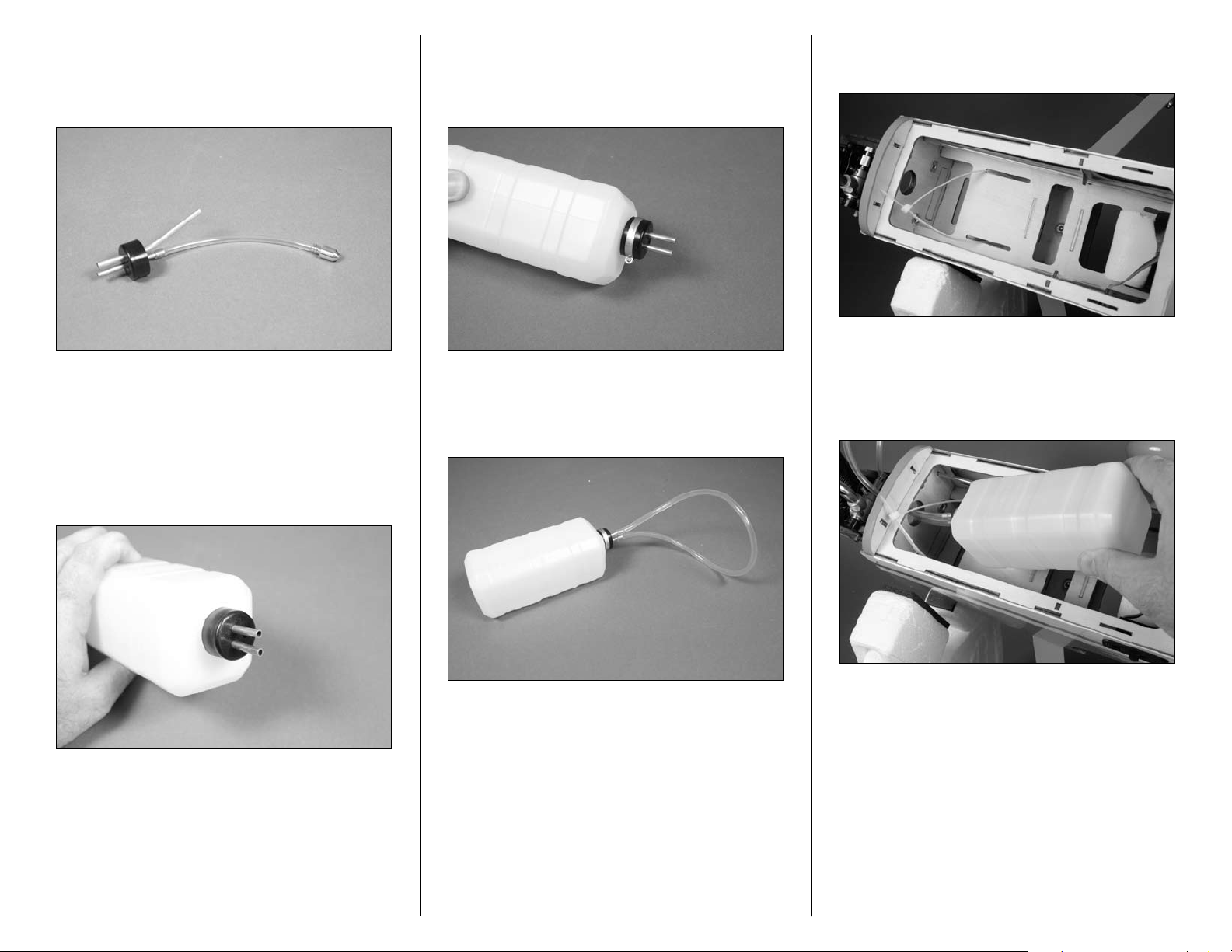
Step 1
Insert the two brass tubes in the stopper. You will need to
use a hobby knife to open two of the holes to insert the
tubes through the stopper.
Note: Always use threadlock on metal-to-metal
fasteners to prevent them from vibrating loose.
Note: The stopper supplied is compatible with both gas
and nitromethane fuels.
23Hangar 9 Pulse 125 ARF Assembly Manual
Page 24
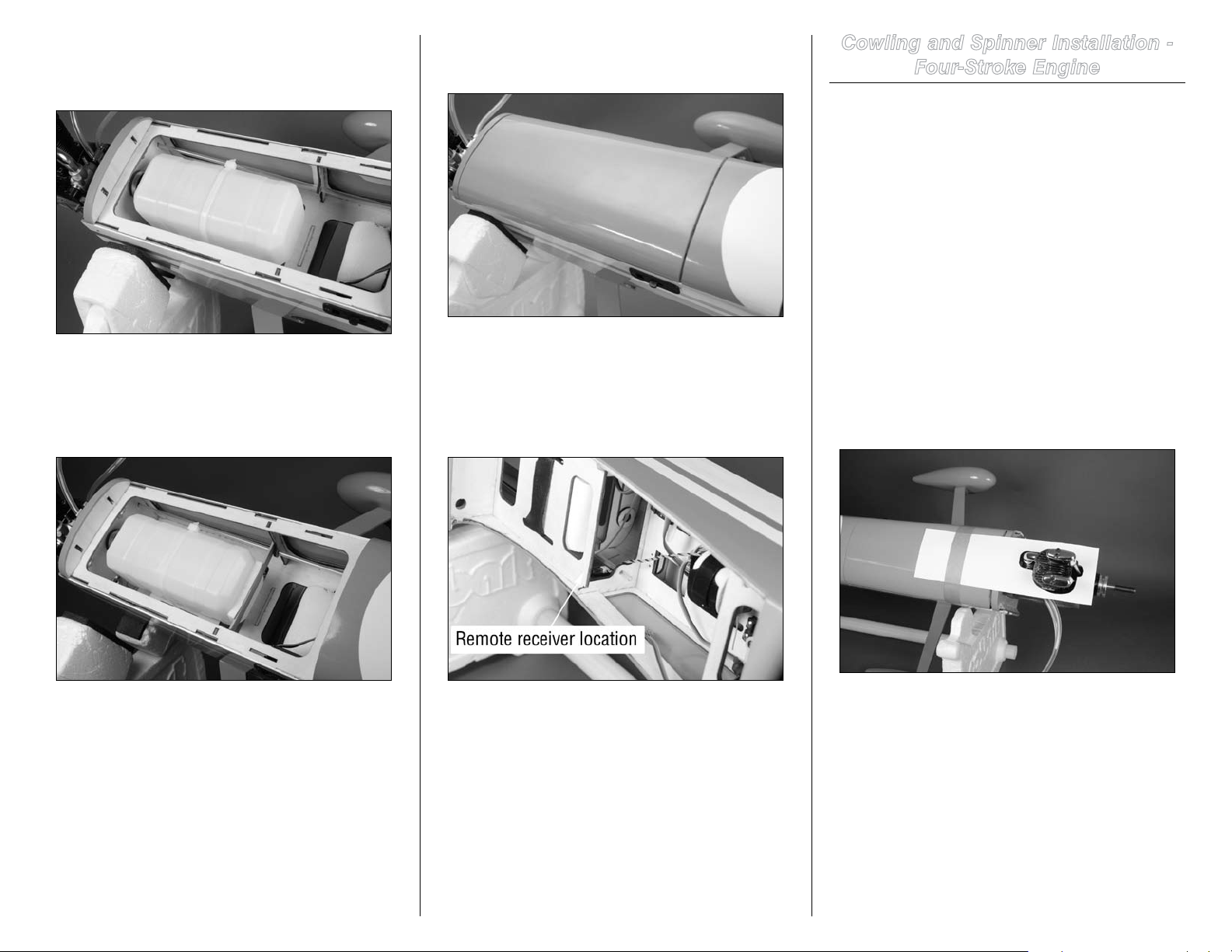
Step 2
Attach the fuel tube designated for the inside of the tank
to the straight brass tube. On the other end of the fuel line
attach the clunk.
Step 3
Insert the stopper on the tank. Make sure the clunk can
move freely inside the tank by having the clunk 1/4-inch
(6mm) from the back of the tank. If the clunk does not move
freely you may experience fuel draw problems. Remove the
stopper and shorten the fuel tube slightly; check and repeat
until it can move freely inside the tank.
Step 4
Use a 2mm x 12mm machine screw and 2mm locknut to
secure the stopper clamp around the stopper. This will keep
the stopper secure on the neck of the fuel tank.
Step 5
Attach the fuel line to the clunk and vent lines of the tank.
The line will be trimmed when it is connected to the engine.
Step 6
Slide the tie wrap through the fuel tank floor as shown.
Step 7
Insert the fuel tank in the fuselage. Make sure the vent line
faces the top of the fuselage. Guide the fuel line through the
hole in the firewall.
24 Hangar 9 Pulse 125 ARF Assembly Manual
Page 25
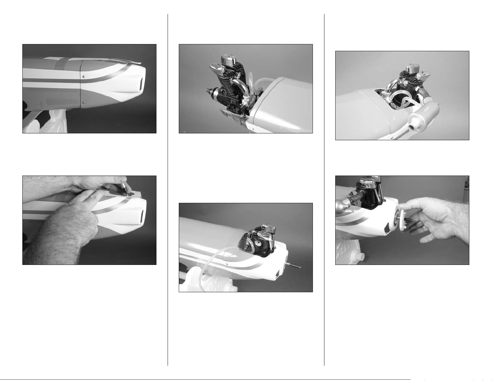
Step 8
Use the tie wrap to secure the fuel tank in the fuselage. Trim
the excess using side cutters.
Step 9
Glue a brace at the rear of the tank to keep it from sliding
back in the fuselage. A piece of foam on the brace will help
hold the tank securely.
Step 10
Attach the hatch back on the fuselage.
Step 11
Use double-sided tape to attach the remote receiver on the
side of the fuselage opposite the throttle servo. The antenna
wires should face up and down for the best reception of your
radio system.
Cowling and Spinner Installation -
Four-Stroke Engine
Required Parts
Fuselage Cowling
Spinner backplate Spinner cone
3mm x 10mm self-tapping screw (2)
3mm x 8mm button head screw (4)
Tools and Adhesives
Cardstock Low-tack tape
Felt-tipped pen Hobby scissors
Phillips screwdriver: #2
Rotary tool with sanding drum
Hex wrench or ball driver: 2mm
Step 1
Cut a piece of cardstock to fit around the engine as shown.
This will be the template for trimming your cowling.
25Hangar 9 Pulse 125 ARF Assembly Manual
Page 26
Step 2
Remove the engine from the firewall. Use four 3mm x 6mm
button head screws to secure the cowl to the fuselage.
Step 4
Use a hobby knife to trim the line coming from the clunk to
attach it to the carburetor.
Step 6
Use the instructions provided with the engine to attach the
muffler. Trim and connect the pressure line from the fuel
tank to the muffler.
Step 3
Use a felt-tipped pen to transfer the outline from the
template on the cowl.
Step 5
Remove the cowl and trim it using the lines made in the
previous step. With the engine back on the firewall, check to
make sure the cowl will fit over the engine. Take your time
trimming the cowl to achieve the best fit. Use a rotary tool
and sanding drum to smooth any rough edges around the
engine.
Step 7
Slide the spinner backplate on the engine shaft.
26 Hangar 9 Pulse 125 ARF Assembly Manual
Page 27
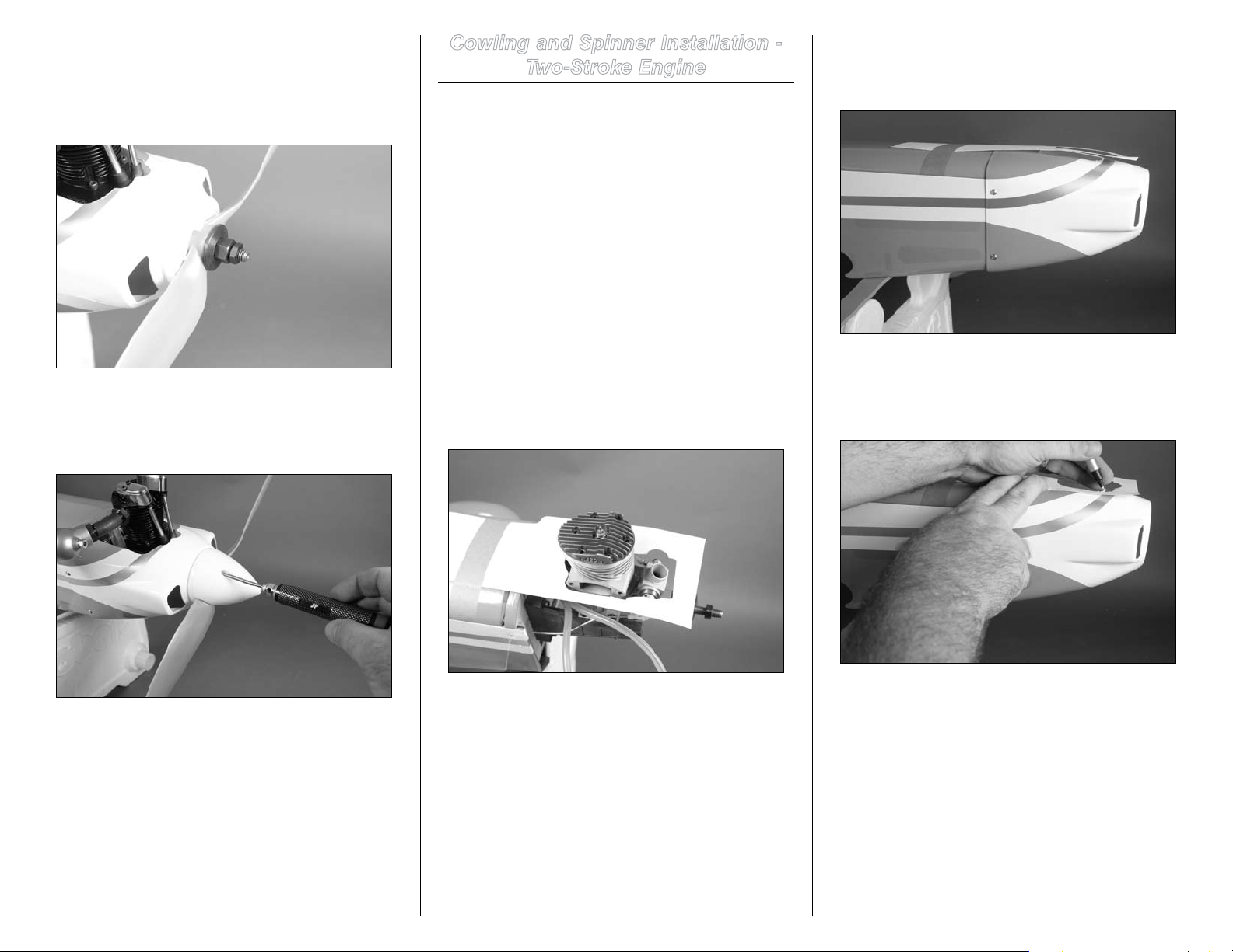
Step 8
Slide the propeller on the engine shaft. Use the hardware
provided with the engine to secure the propeller. The small
standoffs on the spinner backplate will help in aligning the
propeller.
Cowling and Spinner Installation -
Two-Stroke Engine
Required Parts
Fuselage Cowling
Spinner backplate Spinner cone
3mm x 10mm self-tapping screw (2)
3mm x 8mm button head screw (4)
Tools and Adhesives
Cardstock Low-tack tape
Felt-tipped pen Hobby scissors
Phillips screwdriver: #2
Rotary tool with sanding drum
Hex wrench or ball driver: 2mm
Step 2
Remove the engine from the firewall. Use four 3mm x 6mm
button head screws to secure the cowl to the fuselage.
Step 9
Secure the spinner cone to the backplate using two 3mm x
10mm self-tapping screws.
Step 1
Cut a piece of cardstock to fit around the engine as shown.
This will be the template for trimming your cowling.
Step 3
Use a felt-tipped pen to transfer the outline from the
template on the cowl.
27Hangar 9 Pulse 125 ARF Assembly Manual
Page 28
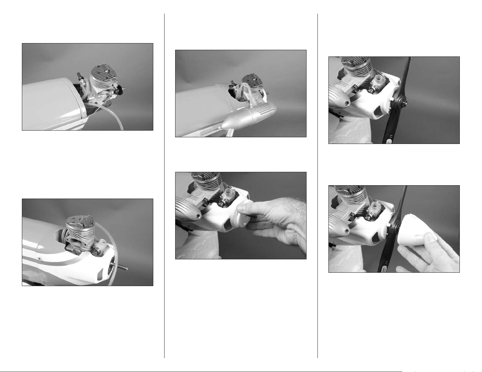
Step 4
Use a hobby knife to trim the line coming from the clunk to
attach it to the carburetor.
Step 5
Remove the cowl and trim it using the lines made in the
previous step. With the engine back on the firewall, check to
make sure the cowl will fit over the engine. Take your time
trimming the cowl to achieve the best fit. Use a rotary tool
and sanding drum to smooth any rough edges around the
engine.
Step 6
Use the instructions provided with the engine to attach the
muffler. Trim and connect the pressure line from the fuel
tank to the muffler.
Step 7
Slide the spinner backplate on the engine shaft.
Step 8
Slide the propeller on the engine shaft. Use the hardware
provided with the engine to secure the propeller. The small
standoffs on the spinner backplate will help in aligning the
propeller.
Step 9
Secure the spinner cone to the backplate using two 3mm x
10mm self-tapping screws.
28 Hangar 9 Pulse 125 ARF Assembly Manual
Page 29
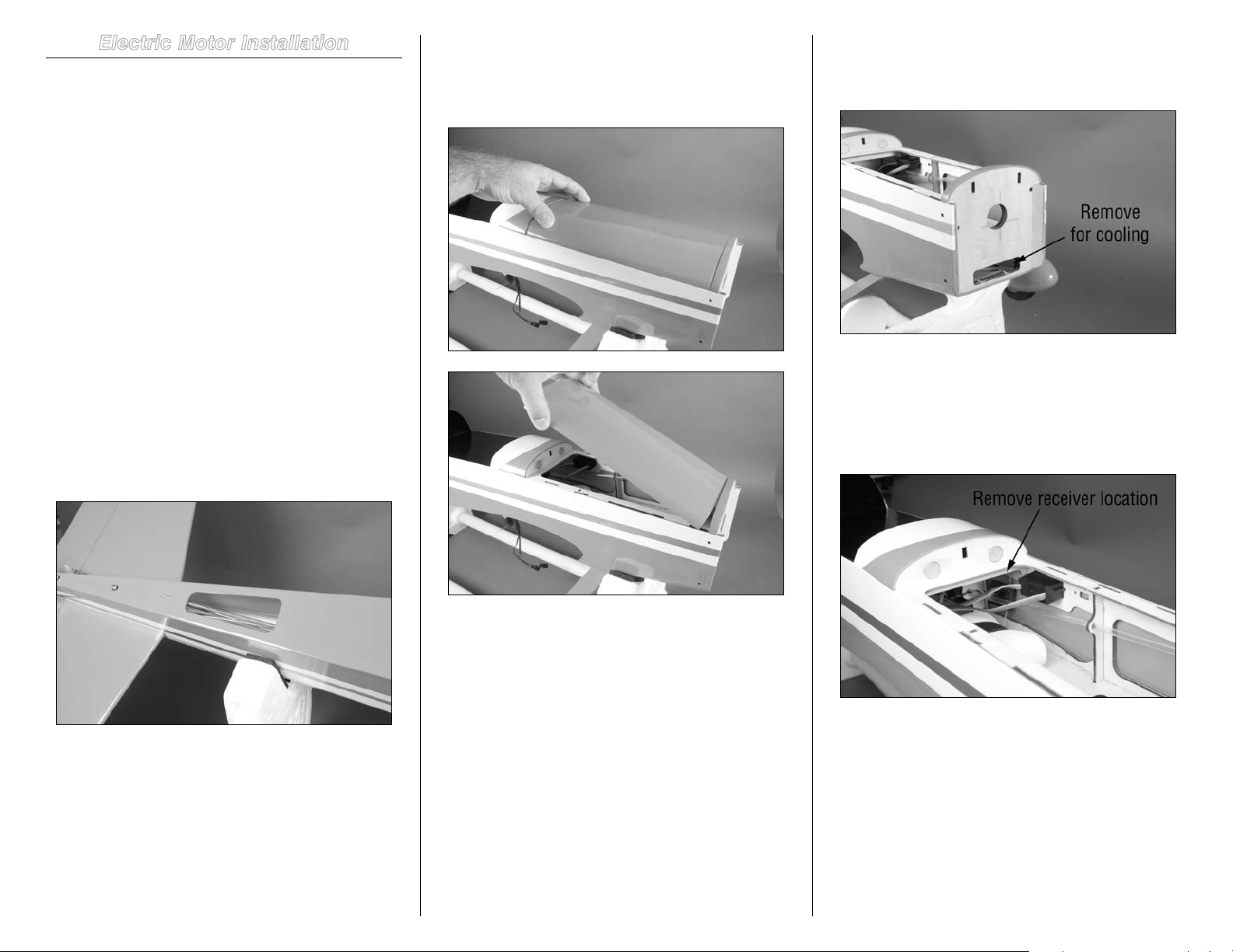
Electric Motor Installation
Required Parts
Fuselage 4mm washer (8)
Motor and related hardware Motor battery (2)
Hook and loop strap (not included)
4mm x 25mm socket head bolt (8)
Aluminum motor standoff, 75mm (4)
Plywood engine mount template
Tools and Adhesives
Covering iron Drill
Low-tack tape
Drill bit: 1/16-inch (1.5mm), 5/32-inch (4mm)
Hex wrench or ball driver: 4mm
Hobby knife with #11 blade
Step 1
Use a hobby knife to remove the covering on the bottom of
the fuselage to allow air to pass though the fuselage. Use a
covering iron to seal the edges around the opening so the
covering does not come loose.
Step 2
Slide the hatch on the fuselage forward to disengage the
magnets at the rear of the hatch. Lift the hatch up at the rear
and remove it from the fuselage.
Step 3
Use a hobby knife and #11 blade to remove the air cooling
tab from the firewall.
Step 4
Use double-sided tape to mount the remote receiver as far
forward in the fuselage as possible. Make sure the antenna
wires are facing vertically when the remove receiver is
installed for the best reception.
29Hangar 9 Pulse 125 ARF Assembly Manual
Page 30
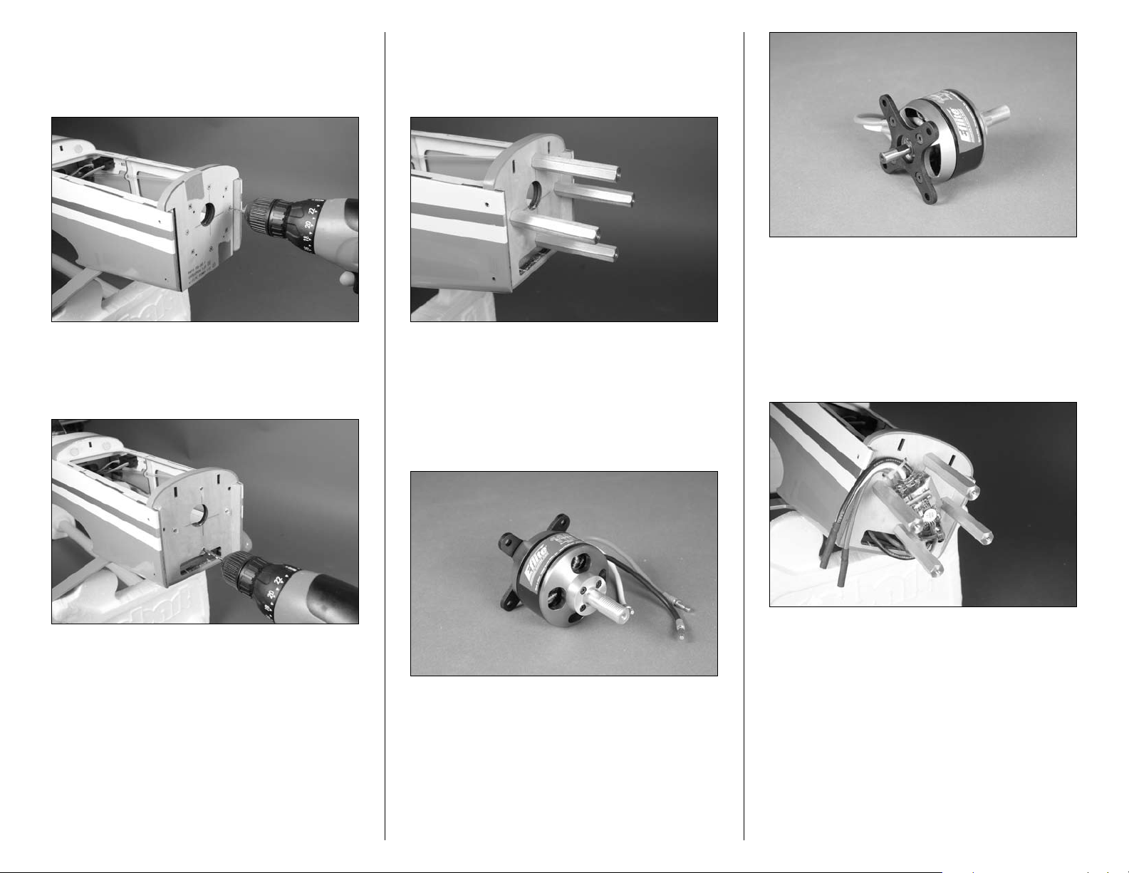
Step 5
Use low-tack tape to attach the firewall template to the
firewall. Use a drill and 1/16-inch (1.5mm) drill bit to drill the
appropriate holes into the firewall.
Step 6
Remove the template and use a 5/32-inch (4mm) drill bit to
enlarge the four holes drilled in the previous step.
Step 7
Use four 4mm x 25mm socket head screws and four 4mm
washers to attach the four aluminum motor standoffs to the
firewall.
Note: Always use threadlock on metal-to-metal
fasteners to prevent them from vibrating loose.
Step 8
Prepare the motor by installing the X-mount and propeller
adapter.
Note: Always use threadlock on metal-to-metal
fasteners to prevent them from vibrating loose.
Step 9
Secure the speed control to the firewall. You may drill a
couple holes in the firewall so tie wraps can be used to fully
secure the speed control position.
30 Hangar 9 Pulse 125 ARF Assembly Manual
Page 31
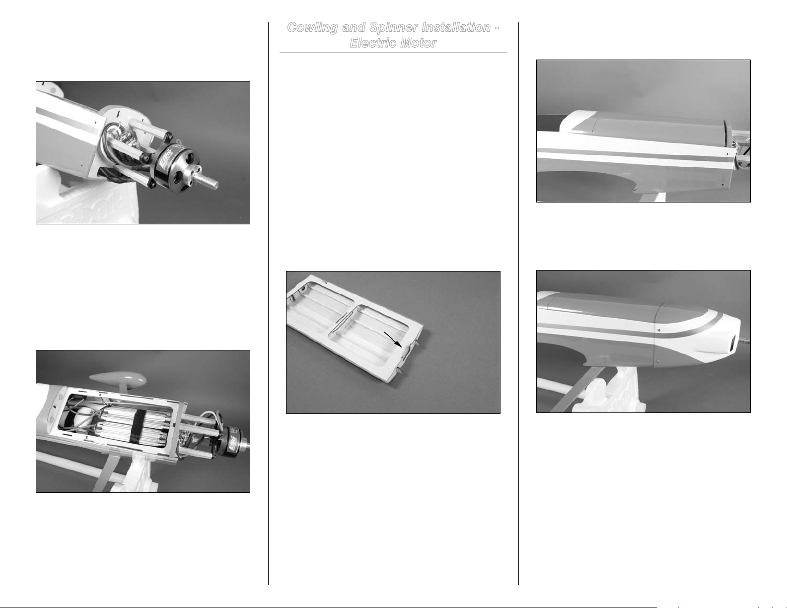
Step 10
Attach the motor to the aluminum motor standoffs using
four 4mm x 25mm socket head screws and four 4mm
washers.
Note: Always use threadlock on metal-to-metal
fasteners to prevent them from vibrating loose.
Step 11
The motor batteries can now be placed in the fuselage. Use
a hook and loop strap (not included) to secure the batteries.
Hook and loop tape can be placed between the batteries and
battery tray to keep them from sliding in the fuselage.
Cowling and Spinner Installation -
Electric Motor
Required Parts
Fuselage Cowling
Spinner backplate Spinner cone
3mm x 10mm self-tapping screw (2)
3mm x 8mm button head screw (4)
Tools and Adhesives
Tapered reamer Phillips screwdriver: #2
Hex wrench or ball driver: 2mm
Rotary tool and sanding drum
Step 1
Use a rotary tool and sanding drum to remove a small
amount of material from the front of the hatch as shown to
clear the upper motor mount bolt.
Step 2
Place hatch back on the fuselage.
Step 3
Use four 3mm x 8mm button head screws to secure the
coaling to the front of the fuselage.
31Hangar 9 Pulse 125 ARF Assembly Manual
Page 32
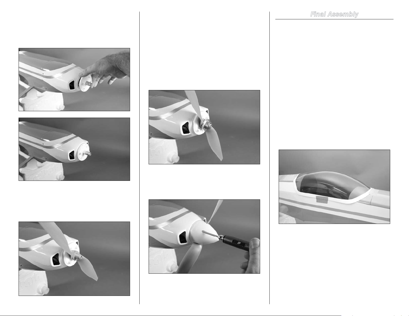
Step 4
Slide the spinner backplate over the propeller adapter. It
may be necessary to enlarge the hole in the center of the
spinner backplate using a tapered reamer so it will fit on the
propeller adapter.
Note: It may be necessary to enlarge the hole in the
center of the propeller using a tapered reamer so it will
fit on the propeller adapter.
Important: Always balance your propeller right before
mounting it to prevent vibrations that could damage the
airframe or motor bearings.
Final Assembly
Required Parts
Fuselage Canopy
Wing panel (left and right) Wing bolt plate
Aluminum wing tube
6mm x 40mm nylon wing bolt (2)
Step 5
Slide the propeller on the propeller adapter. The small
standoffs on the spinner backplate will help in aligning the
propeller.
Step 6
Secure the propeller using a box wrench and the hardware
from the adapter.
Step 7
Secure the spinner cone to the backplate using two 3mm x
10mm self-tapping screws.
Tools and Adhesives
Canopy glue Medium grit sandpaper
Paper towel Rubbing alcohol
Low-tack tape
Step 1
Use medium grit sandpaper to lightly sand the inside edge
of the canopy where it contacts the fuselage. Use a paper
towel and rubbing alcohol to remove any oil or debris after
sanding. Apply a thin bead of canopy glue to the inside edge
of the canopy. Use low-tack tape to hold the canopy securely
on the fuselage until the glue fully cures.
32 Hangar 9 Pulse 125 ARF Assembly Manual
Page 33
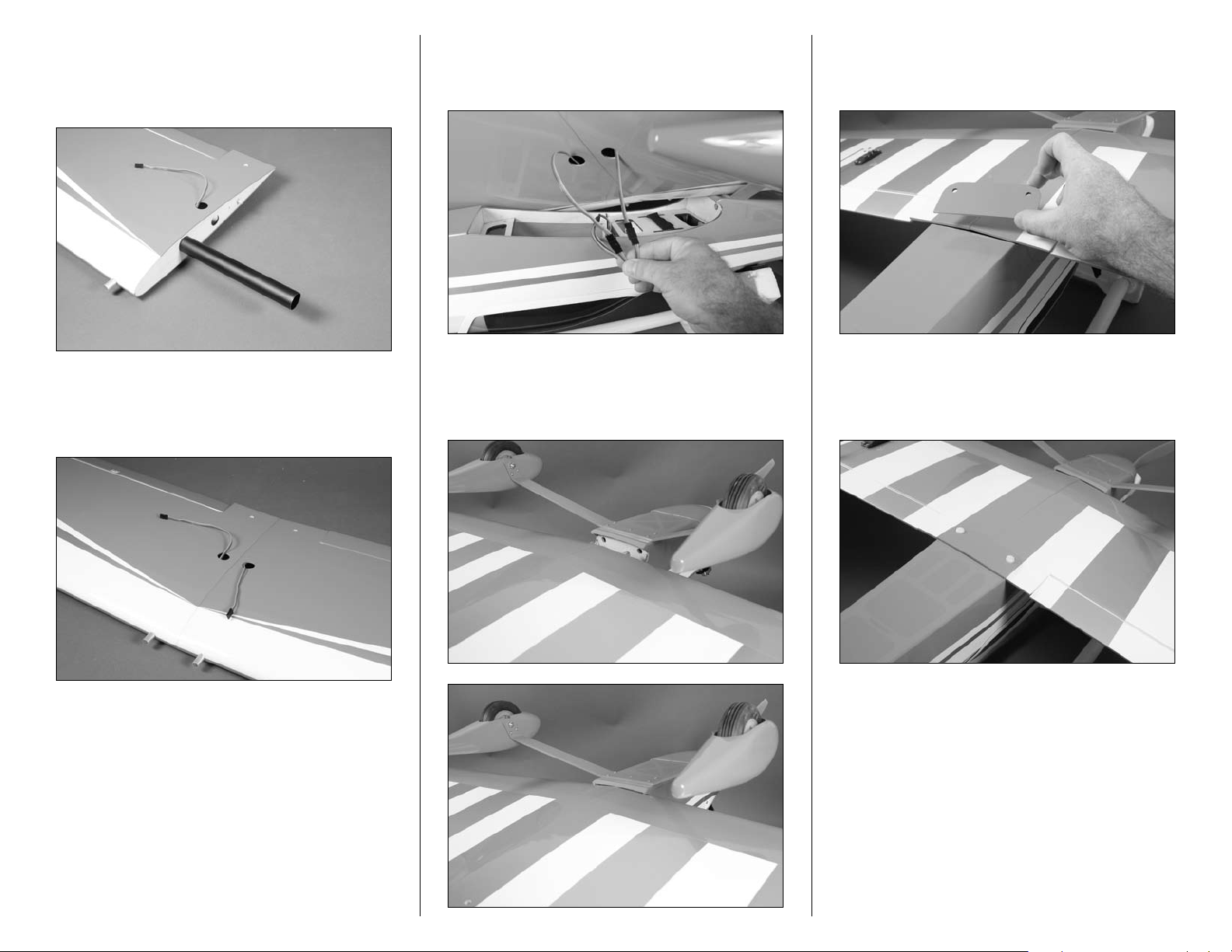
Step 2
Slide the aluminum wing tube into one of the wing panels. It
will only slide in so far: don’t try and force it further than it
will easily slide.
Step 4
Connect the leads from the aileron servos into the leads
coming from the aileron port of the receiver.
Step 6
Place the wing bolt plate in position. The rounded edges of
the plate face to the front of the aircraft.
Step 3
Slide the remaining wing panel on the tube. The two panels
will fit tightly together.
Step 5
Place the wing on the bottom of the fuselage. Slide the wing
forward so the wing dowels go into the hole in the fuselage.
Step 7
Secure the wing to the fuselage using two 6mm x 40mm
nylon wing bolts.
33Hangar 9 Pulse 125 ARF Assembly Manual
Page 34
Center of Gravity
An important part of preparing the aircraft for flight
is properly balancing the model.
Caution: Do not inadvertently skip this step!
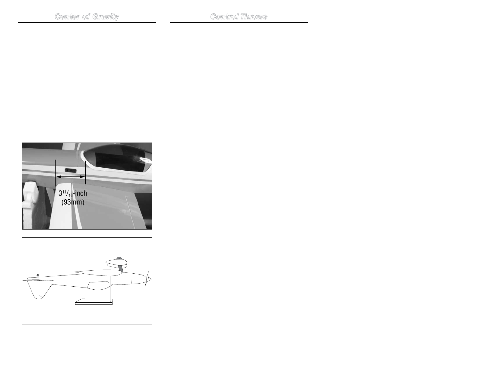
The recommended Center of Gravity (CG) location for the
your model is 311/16-inch (93mm) back from the leading edge
of the wing. Mark the location for the Center of Gravity on
the bottom of the wing next to the fuselage as shown. The
CG range for your model is 31/2 to 37/8 inches (90mm to
98mm) from the leading edge of the wing
When balancing your model, support the plane upright at the
marks made on the bottom of the wing with your fingers or
a commercially available balancing stand. This is the correct
balance point for your model. You might find you may be
required to add a small amount of weight to either the front
or back of the fuselage to achieve the correct balance.
Control Throws
Step 1
Turn on the transmitter and receiver of your model. Check
the movement of the rudder using the transmitter. When
the stick is moved right, the rudder should also move right.
Reverse the direction of the servo at the transmitter if
necessary.
Step 2
Check the movement of the elevator with the radio system.
Moving the elevator stick toward the bottom of the
transmitter will make the airplane elevator move up.
Step 3
Check the movement of the ailerons with the radio system.
Moving the aileron stick right will make the right aileron
move up and the left aileron move down.
Step 4
Use a ruler to adjust the throw of the elevator, ailerons and
rudder.
Aileron High Rate
Up 3/4-inch (20mm) 22 Degrees
Down 3/4-inch (20mm) 22 Degrees
Aileron Low Rate
Up 1/2-inch (15mm) 16 Degrees
Down 1/2-inch (15mm) 16 Degrees
Elevator High Rate
Up 3/4-inch (20mm) 22 Degrees
Down 3/4-inch (20mm) 22 Degrees
Elevator Low Rate
Up 5/8-inch (16mm) 17 Degrees
Down 5/8-inch (16mm) 17 Degrees
Rudder High Rate
Left 3/4-inch (20mm) 22 Degrees
Right 3/4-inch (20mm) 22 Degrees
Rudder Low Rate
Left 1/2-inch (15mm) 16 Degrees
Right 1/2-inch (15mm) 16 Degrees
Note: Measurements are taken at the inner or widest
point on the control surface.
These are general guidelines measured from our own flight
tests. You can experiment with higher rates to match your
preferred style of flying.
Note: Travel Adjust, Sub-Trim and Dual Rates are
not listed and should be adjusted according to each
individual model and preference.
After the first flights, the CG position can be adjusted for
your personal preference.
34 Hangar 9 Pulse 125 ARF Assembly Manual
Page 35

Flight Preparations
Safety Do’s and Don’ts for Pilots
Daily Flight Checks
Flight preparations must be checked each time you travel
to the flying field. Because your model will encounter a
variety of situations, it is best to keep an eye on the various
components of your model to keep it in the best flying
condition.
Checking the Frequency
When using a Spektrum radio system, follow the guidelines
for use of DSM radio systems at your particular field.
Checking the Controls
Before starting your engine, check to make sure the controls
are operating in the correct directions and the linkages and
surfaces are not binding anywhere. Also look at the clevises
and clevis retainers to make sure they are secure and will not
come loose or fail in flight.
Fueling your Model
Fill the fuel tank with the proper fuel. Fill the tank by
connecting the fuel pump to the line going to the needle
valve or to the fuel dot on the side of the cowling.
Disconnect the fuel line attached to the pressure fitting of the
muffler; your tank is full when fuel begins to run out of the
pressure line. Reconnect the fuel lines to the needle valve
assembly or insert the plug into the fuel dot and connect the
line to the muffler.
Note: It is very important to reconnect the lines to the
correct place. If they are reconnected incorrectly, the
engine will not run properly.
• Ensure that your batteries have been properly charged
prior to your initial flight.
• Keep track of the time the system is turned on so
you will know how long you can safely operate your
system.
• Perform a ground range check prior to the initial flight
of the day. See the “Daily Flight Checks Section” for
information.
• Check all control surfaces prior to each takeoff.
• Do not fly your model near spectators, parking areas or
any other area that could result in injury to people or
damage of property.
• Do not fly during adverse weather conditions. Poor
visibility can cause disorientation and loss of control of
your aircraft. Strong winds can cause similar problems.
• Do not point the transmitter antenna directly toward the
model. The radiation pattern from the tip of the antenna
is inherently low.
• Do not take chances. If at any time during flight
you observe any erratic or abnormal operation, land
immediately and do not resume flight until the cause of
the problem has been ascertained and corrected. Safety
can never be taken lightly.
Dual Rate Recommendations
• We recommend that the rudder dual rate be set to Low
for takeoff to help minimize overcorrection during the
takeoff roll.
• We recommend the rudder dual rate be set to High
for landing to help maintain heading as the model
transitions from flying speed to taxi speeds.
• Elevator and Aileron dual rates should be adjusted
for personal feel and also if there is any unusual wind
conditions.
Step 1
Check the battery voltage on both the transmitter and
the receiver battery packs. Do not fly below 4.3V on the
transmitter if you are using a Spektrum transmitter that uses
4-cells to power the transmitter. Do not fly below 9.5V on
the transmitter if you are using a JR or Spektrum transmitter
that uses 8-cells to power the transmitter. Do not fly if the
receiver pack is at or below 4.7V. To do so can crash your
aircraft.
Note: When you check these batteries, ensure that
you have the polarities correct on your expanded scale
voltmeter.
Step 2
Check all hardware (linkages, screws, nuts, and bolts) prior
to each day’s flight. Be sure that binding does not occur and
that all parts are properly secured.
Step 3
Ensure that all surfaces are moving in the proper manner.
Step 4
Perform a ground range check before each day’s flying
session.
Step 5
Prior to starting your aircraft, turn off your transmitter, then
turn it back on. Do this each time you start your aircraft.
If any critical switches are on without your knowledge, the
transmitter alarm will warn you at this time.
Step 6
Check that all trim levers are in the proper location.
Step 7
All servo pigtails and switch harness plugs should be
secured in the receiver. Make sure that the switch harness
moves freely in both directions.
35Hangar 9 Pulse 125 ARF Assembly Manual
Page 36

Age Requirements
Age Recommendation: 14 years or over. This is not a toy.
This product is not intended for use by children without
direct adult supervision.
Safety, Precautions and Warnings
As the user of this product, you are solely responsible for
operating it in a manner that does not endanger yourself and
others or result in damage to the product or the property of
others.
Carefully follow the directions and warnings for this and any
optional support equipment (chargers, rechargeable battery
packs, etc.) that you use.
This model is controlled by a radio signal that is subject to
interference from many sources outside your control. This
interference can cause momentary loss of control so it is
necessary to always keep a safe distance in all directions
around your model, as this margin will help to avoid
collisions or injury.
• Always operate your model in an open area away from
cars, traffic or people.
• Avoid operating your model in the street where injury or
damage can occur.
• Never operate the model out into the street or populated
areas for any reason.
• Never operate your model with low transmitter batteries.
• Carefully follow the directions and warnings for this and
any optional support equipment (chargers, rechargeable
battery packs, etc.) that you use.
• Keep all chemicals, small parts and anything electrical out
of the reach of children.
• Moisture causes damage to electronics. Avoid water
exposure to all equipment not specifically designed and
protected for this purpose.
Warranty Information
WARRANTY PERIOD
Exclusive Warranty- Horizon Hobby, Inc., (Horizon)
warranties that the Products purchased (the “Product”) will
be free from defects in materials and workmanship at the
date of purchase by the Purchaser.
LIMITED WARRANTY
(a) This warranty is limited to the original Purchaser
(“Purchaser”) and is not transferable. REPAIR OR
REPLACEMENT AS PROVIDED UNDER THIS WARRANTY
IS THE EXCLUSIVE REMEDY OF THE PURCHASER. This
warranty covers only those Products purchased from an
authorized Horizon dealer. Third party transactions are not
covered by this warranty. Proof of purchase is required
for warranty claims. Further, Horizon reserves the right to
change or modify this warranty without notice and disclaims
all other warranties, express or implied.
(b) Limitations- HORIZON MAKES NO WARRANTY OR
REPRESENTATION, EXPRESS OR IMPLIED, ABOUT
NON-INFRINGEMENT, MERCHANTABILITY OR FITNESS
FOR A PARTICULAR PURPOSE OF THE PRODUCT. THE
PURCHASER ACKNOWLEDGES THAT THEY ALONE HAVE
DETERMINED THAT THE PRODUCT WILL SUITABLY MEET
THE REQUIREMENTS OF THE PURCHASER’S INTENDED
USE.
(c) Purchaser Remedy- Horizon’s sole obligation hereunder
shall be that Horizon will, at its option, (i) repair or (ii)
replace, any Product determined by Horizon to be defective.
In the event of a defect, these are the Purchaser’s exclusive
remedies. Horizon reserves the right to inspect any and
all equipment involved in a warranty claim. Repair or
replacement decisions are at the sole discretion of Horizon.
This warranty does not cover cosmetic damage or damage
due to acts of God, accident, misuse, abuse, negligence,
commercial use, or modification of or to any part of the
Product. This warranty does not cover damage due to
improper installation, operation, maintenance, or attempted
repair by anyone other than Horizon. Return of any goods
by Purchaser must be approved in writing by Horizon before
shipment.
DAMAGE LIMITS
HORIZON SHALL NOT BE LIABLE FOR SPECIAL, INDIRECT
OR CONSEQUENTIAL DAMAGES, LOSS OF PROFITS OR
PRODUCTION OR COMMERCIAL LOSS IN ANY WAY
CONNECTED WITH THE PRODUCT, WHETHER SUCH CLAIM
IS BASED IN CONTRACT, WARRANTY, NEGLIGENCE, OR
STRICT LIABILITY. Further, in no event shall the liability of
Horizon exceed the individual price of the Product on which
liability is asserted. As Horizon has no control over use,
setup, final assembly, modification or misuse, no liability
shall be assumed nor accepted for any resulting damage or
injury. By the act of use, setup or assembly, the user accepts
all resulting liability.
If you as the Purchaser or user are not prepared to accept
the liability associated with the use of this Product, you
are advised to return this Product immediately in new and
unused condition to the place of purchase.
Law: These Terms are governed by Illinois law (without
regard to conflict of law principals).
SAFETY PRECAUTIONS
This is a sophisticated hobby Product and not a toy. It must
be operated with caution and common sense and requires
some basic mechanical ability. Failure to operate this Product
in a safe and responsible manner could result in injury or
damage to the Product or other property. This Product
is not intended for use by children without direct adult
supervision. The Product manual contains instructions for
safety, operation and maintenance. It is essential to read and
follow all the instructions and warnings in the manual, prior
to assembly, setup or use, in order to operate correctly and
avoid damage or injury.
QUESTIONS, ASSISTANCE, AND REPAIRS
Your local hobby store and/or place of purchase cannot
provide warranty support or repair. Once assembly, setup
or use of the Product has been started, you must contact
Horizon directly. This will enable Horizon to better answer
your questions and service you in the event that you may
need any assistance. For questions or assistance, please
direct your email to [email protected], or
call 877.504.0233 toll free to speak to a service technician.
36 Hangar 9 Pulse 125 ARF Assembly Manual
Page 37

INSPECTION OR REPAIRS
If this Product needs to be inspected or repaired, please
call for a Return Merchandise Authorization (RMA). Pack
the Product securely using a shipping carton. Please note
that original boxes may be included, but are not designed
to withstand the rigors of shipping without additional
protection. Ship via a carrier that provides tracking and
insurance for lost or damaged parcels, as Horizon is not
responsible for merchandise until it arrives and is accepted
at our facility. A Service Repair Request is available at www.
horizonhobby.com on the “Support” tab. If you do not have
internet access, please include a letter with your complete
name, street address, email address and phone number
where you can be reached during business days, your RMA
number, a list of the included items, method of payment
for any non-warranty expenses and a brief summary of the
problem. Your original sales receipt must also be included
for warranty consideration. Be sure your name, address,
and RMA number are clearly written on the outside of the
shipping carton.
WARRANTY INSPECTION AND REPAIRS
To receive warranty service, you must include your original
sales receipt verifying the proof-of-purchase date. Provided
warranty conditions have been met, your Product will be
repaired or replaced free of charge. Repair or replacement
decisions are at the sole discretion of Horizon Hobby.
NON-WARRANTY REPAIRS
Should your repair not be covered by warranty the repair
will be completed and payment will be required without
notification or estimate of the expense unless the expense
exceeds 50% of the retail purchase cost. By submitting the
item for repair you are agreeing to payment of the repair
without notification. Repair estimates are available upon
request. You must include this request with your repair. Nonwarranty repair estimates will be billed a minimum of 1/2
hour of labor. In addition you will be billed for return freight.
Please advise us of your preferred method of payment.
Horizon accepts money orders and cashiers checks, as
well as Visa, MasterCard, American Express, and Discover
cards. If you choose to pay by credit card, please include
your credit card number and expiration date. Any repair
left unpaid or unclaimed after 90 days will be considered
abandoned and will be disposed of accordingly. Please note:
non-warranty repair is only available on electronics and
model engines.
United States:
Electronics and engines requiring inspection or repair should
be shipped to the following address:
Horizon Service Center
4105 Fieldstone Road
Champaign, Illinois 61822
USA
All other Products requiring warranty inspection or repair
should be shipped to the following address:
Horizon Product Support
4105 Fieldstone Road
Champaign, Illinois 61822
USA
Please call 877-504-0233 or e-mail us at productsupport@
horizonhobby.com with any questions or concerns regarding
this product or warranty.
United Kingdom:
Electronics and engines requiring inspection or repair should
be shipped to the following address:
Horizon Hobby UK
Units 1-4 Ployters Rd
Staple Tye
Harlow, Essex
CM18 7NS
United Kingdom
Please call +44 (0) 1279 641 097 or e-mail us at sales@
horizonhobby.co.uk with any questions or concerns
regarding this product or warranty.
Germany:
Electronics and engines requiring inspection or repair should
be shipped to the following address:
Horizon Technischer Service
Hamburger Strasse 10
25335 Elmshorn
Germany
Please call +49 4121 46199 66 or e-mail us at service@
horizonhobby.de with any questions or concerns regarding
this product or warranty.
CE Compliance Information for the
European Union
INSTRUCTIONS FOR DISPOSAL OF WEEE BY
USERS IN THE EUROPEAN UNION
This product must not be disposed of with other waste.
Instead, it is the user’s responsibility to dispose of their
waste equipment by handing it over to a designated
collection point for the recycling of waste electrical and
electronic equipment. The separate collection and recycling
of your waste equipment at the time of disposal will help to
conserve natural resources and ensure that it is recycled in
a manner that protects human health and the environment.
For more information about where you can drop off your
waste equipment for recycling, please contact your local city
office, your household waste disposal service or where you
purchased the product.
37Hangar 9 Pulse 125 ARF Assembly Manual
Page 38

2009 Official Academy of Model
Aeronautics Safety Code
GENERAL
1. A model aircraft shall be defined as a non-humancarrying device capable of sustained flight in the
atmosphere. It shall not exceed limitations established
in this code and is intended to be used exclusively for
recreational or competition activity.
2. The maximum takeoff weight of a model aircraft,
including fuel, is 55 pounds, except for those flown
under the AMA Experimental Aircraft Rules.
3. I will abide by this Safety Code and all rules established
for the flying site I use. I will not willfully fly my model
aircraft in a reckless and/or dangerous manner.
4. I will not fly my model aircraft in sanctioned events,
air shows, or model demonstrations until it has been
proven airworthy.
5. I will not fly my model aircraft higher than approximately
400 feet above ground level, when within three (3) miles
of an airport without notifying the airport operator. I will
yield the right-of-way and avoid flying in the proximity of
full-scale aircraft, utilizing a spotter when appropriate.
6. I will not fly my model aircraft unless it is identified with
my name and address, or AMA number, inside or affixed
to the outside of the model aircraft. This does not apply
to model aircraft flown indoors.
7. I will not operate model aircraft with metal-blade
propellers or with gaseous boosts (other than air),
nor will I operate model aircraft with fuels containing
tetranitromethane or hydrazine.
8. I will not operate model aircraft carrying pyrotechnic
devices which explode burn, or propel a projectile of
any kind. Exceptions include Free Flight fuses or devices
that burn producing smoke and are securely attached
to the model aircraft during flight. Rocket motors up
to a G-series size may be used, provided they remain
firmly attached to the model aircraft during flight. Model
rockets may be flown in accordance with the National
Model Rocketry Safety Code; however, they may not
be launched from model aircraft. Officially designated
AMAAir Show Teams (AST) are authorized to use
devices and practices as defined within the Air Show
Advisory Committee Document.
9. I will not operate my model aircraft while under the
influence of alcohol or within eight (8) hours of having
consumed alcohol.
10. I will not operate my model aircraft while using any drug
which could adversely affect my ability to safely control
my model aircraft.
11. Children under six (6) years old are only allowed on a
flightline or in a flight area as a pilot or while under flight
instruction.
12. When and where required by rule, helmets must be
properly worn and fastened. They must be OSHA, DOT,
ANSI, SNELL or NOCSAE approved or comply with
comparable standards.
RADIO CONTROL
1. All model flying shall be conducted in a manner to avoid
over flight of unprotected people.
2. I will have completed a successful radio equipment
ground-range check before the first flight of a new or
repaired model aircraft.
3. I will not fly my model aircraft in the presence of
spectators until I become a proficient flier, unless I am
assisted by an experienced pilot.
4. At all flying sites a line must be established, in front of
which all flying takes place. Only personnel associated
with flying the model aircraft are allowed at or in front of
the line. In the case of airshows demonstrations straight
line must be established. An area away from the line
must be maintained for spectators. Intentional flying
behind the line is prohibited.
5. I will operate my model aircraft using only radiocontrol frequencies currently allowed by the Federal
Communications Commission (FCC). Only individuals
properly licensed by the FCC are authorized to operate
equipment on Amateur Band frequencies.
6. I will not knowingly operate my model aircraft
within three (3) miles of any preexisting flying site
without a frequency-management agreement. A
frequencymanagement agreement may be an allocation
of frequencies for each site, a day-use agreement
between sites, or testing which determines that no
interference exists. A frequency-management agreement
may exist between two or more AMA chartered clubs,
AMA clubs and individual AMA members, or individual
AMA members. Frequency-management agreements,
including an interference test report if the agreement
indicates no interference exists, will be signed by all
parties and copies provided to AMA Headquarters.
7. With the exception of events flown under official AMA
rules, no powered model may be flown outdoors closer
than 25 feet to any individual, except for the pilot and
located at the flightline.
8. Under no circumstances may a pilot or other person
touch a model aircraft in flight while it is still under
power, except to divert it from striking an individual.
9. Radio-controlled night flying is limited to lowperformance model aircraft (less than 100 mph). The
model aircraft must be equipped with a lighting system
which clearly defines the aircraft’s attitude and direction
at all times.
10. The operator of a radio-controlled model aircraft shall
control it during the entire flight, maintaining visual
contact without enhancement other than by corrective
lenses that are prescribed for the pilot. No model aircraft
shall be equipped with devices which allow it to be flown
to a selected location which is beyond the visual range
of the pilot.
38 Hangar 9 Pulse 125 ARF Assembly Manual
Page 39
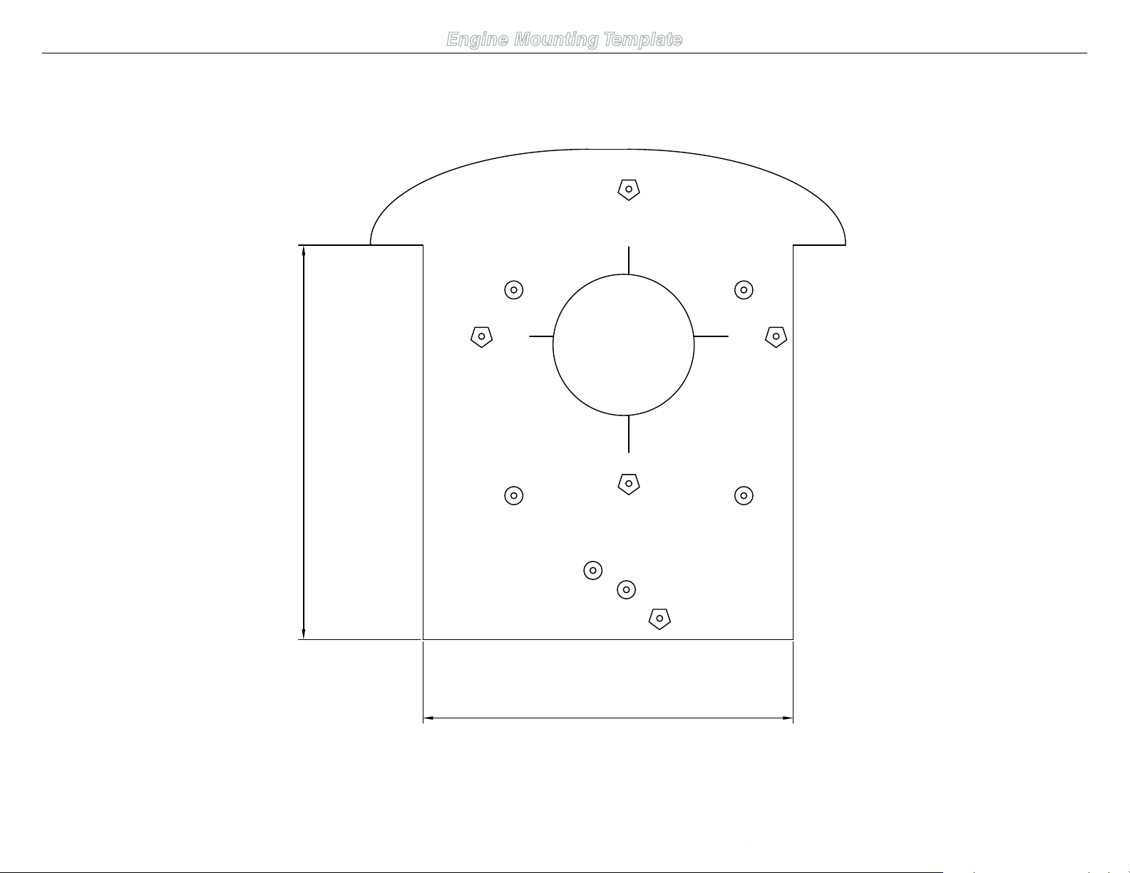
SAITO 1.25
EVOLUTION 1.20
E-FLITE POWER 110
3.69-inch (91.73mm)
3.69-inch (97.73mm)
Engine Mounting Template
39Hangar 9 Pulse 125 ARF Assembly Manual
Page 40

© 2009 Horizon Hobby, Inc.
4105 Fieldstone Road
Champaign, Illinois 61822
USA
(877) 504-0233
horizonhobby.com
Hangar-9.com
15369 Printed 07/09
 Loading...