

Page 1
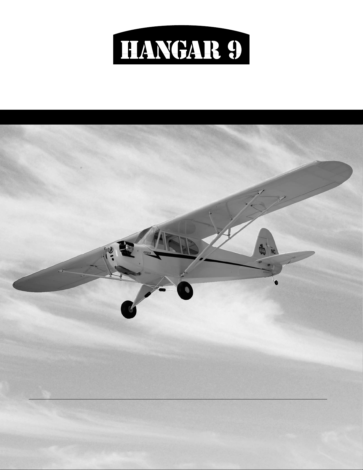
Piper J-3 Cub 40
ASSEMBLY MANUAL
Specifications
Wingspan: ....................................... 80" (2032mm)
Fuselage length: ........................... 49.9" (1268mm)
Wing area: ........................ 919 sq. in. (59.3 sq dm)
Weight: ............................ 6.75–7.5 lbs (3–3.4 kg)
Engine: ............ .36–.46 2-stroke, .56–.82 4-stroke
Radio: ................................. 4-channel w/ 5 servos
Page 2

Table of Contents
Contents of Kit . . . . . . . . . . . . . . . . . . . . . . . . . . . . . . . . . . . . . . . . . . . . . . . . . . . . . . . . . . . . . . . . . . . .3
Additional Required Equipment. . . . . . . . . . . . . . . . . . . . . . . . . . . . . . . . . . . . . . . . . . . . . . . . . . . . . . . .3
Covering Colors . . . . . . . . . . . . . . . . . . . . . . . . . . . . . . . . . . . . . . . . . . . . . . . . . . . . . . . . . . . . . . . . . . .3
Additional Required Tools and Adhesives. . . . . . . . . . . . . . . . . . . . . . . . . . . . . . . . . . . . . . . . . . . . . . . .4
Field Equipment Required. . . . . . . . . . . . . . . . . . . . . . . . . . . . . . . . . . . . . . . . . . . . . . . . . . . . . . . . . . . .4
Warning . . . . . . . . . . . . . . . . . . . . . . . . . . . . . . . . . . . . . . . . . . . . . . . . . . . . . . . . . . . . . . . . . . . . . . . . .4
Using the Manual . . . . . . . . . . . . . . . . . . . . . . . . . . . . . . . . . . . . . . . . . . . . . . . . . . . . . . . . . . . . . . . . . .4
Before Starting Assembly . . . . . . . . . . . . . . . . . . . . . . . . . . . . . . . . . . . . . . . . . . . . . . . . . . . . . . . . . . . .5
Warranty Information . . . . . . . . . . . . . . . . . . . . . . . . . . . . . . . . . . . . . . . . . . . . . . . . . . . . . . . . . . . . . . .5
Section 1: Hinge Installation. . . . . . . . . . . . . . . . . . . . . . . . . . . . . . . . . . . . . . . . . . . . . . . . . . . . . . . . . .6
Section 2: Engine Installation . . . . . . . . . . . . . . . . . . . . . . . . . . . . . . . . . . . . . . . . . . . . . . . . . . . . . . . . .9
Section 3: Servo Installation (Aileron) . . . . . . . . . . . . . . . . . . . . . . . . . . . . . . . . . . . . . . . . . . . . . . . . .11
Section 4: Servo Installation (Fuselage) . . . . . . . . . . . . . . . . . . . . . . . . . . . . . . . . . . . . . . . . . . . . . . . .15
Section 5: Window Installation . . . . . . . . . . . . . . . . . . . . . . . . . . . . . . . . . . . . . . . . . . . . . . . . . . . . . . .20
Section 6: Landing Gear Installation. . . . . . . . . . . . . . . . . . . . . . . . . . . . . . . . . . . . . . . . . . . . . . . . . . .21
Section 7: Installing the Stabilizer. . . . . . . . . . . . . . . . . . . . . . . . . . . . . . . . . . . . . . . . . . . . . . . . . . . . .23
Section 8: Cowling Installation. . . . . . . . . . . . . . . . . . . . . . . . . . . . . . . . . . . . . . . . . . . . . . . . . . . . . . .26
Section 9: Wing Installation . . . . . . . . . . . . . . . . . . . . . . . . . . . . . . . . . . . . . . . . . . . . . . . . . . . . . . . . .28
Adjusting the Engine. . . . . . . . . . . . . . . . . . . . . . . . . . . . . . . . . . . . . . . . . . . . . . . . . . . . . . . . . . . . . . .31
Control Throws. . . . . . . . . . . . . . . . . . . . . . . . . . . . . . . . . . . . . . . . . . . . . . . . . . . . . . . . . . . . . . . . . . .31
Recommended CG . . . . . . . . . . . . . . . . . . . . . . . . . . . . . . . . . . . . . . . . . . . . . . . . . . . . . . . . . . . . . . . .32
Preflight . . . . . . . . . . . . . . . . . . . . . . . . . . . . . . . . . . . . . . . . . . . . . . . . . . . . . . . . . . . . . . . . . . . . . . . .32
Range Testing the Radio . . . . . . . . . . . . . . . . . . . . . . . . . . . . . . . . . . . . . . . . . . . . . . . . . . . . . . . . . . . .33
2005 Official AMA National Model Aircraft Safety Code. . . . . . . . . . . . . . . . . . . . . . . . . . . . . . . . . . . .34
2
Page 3
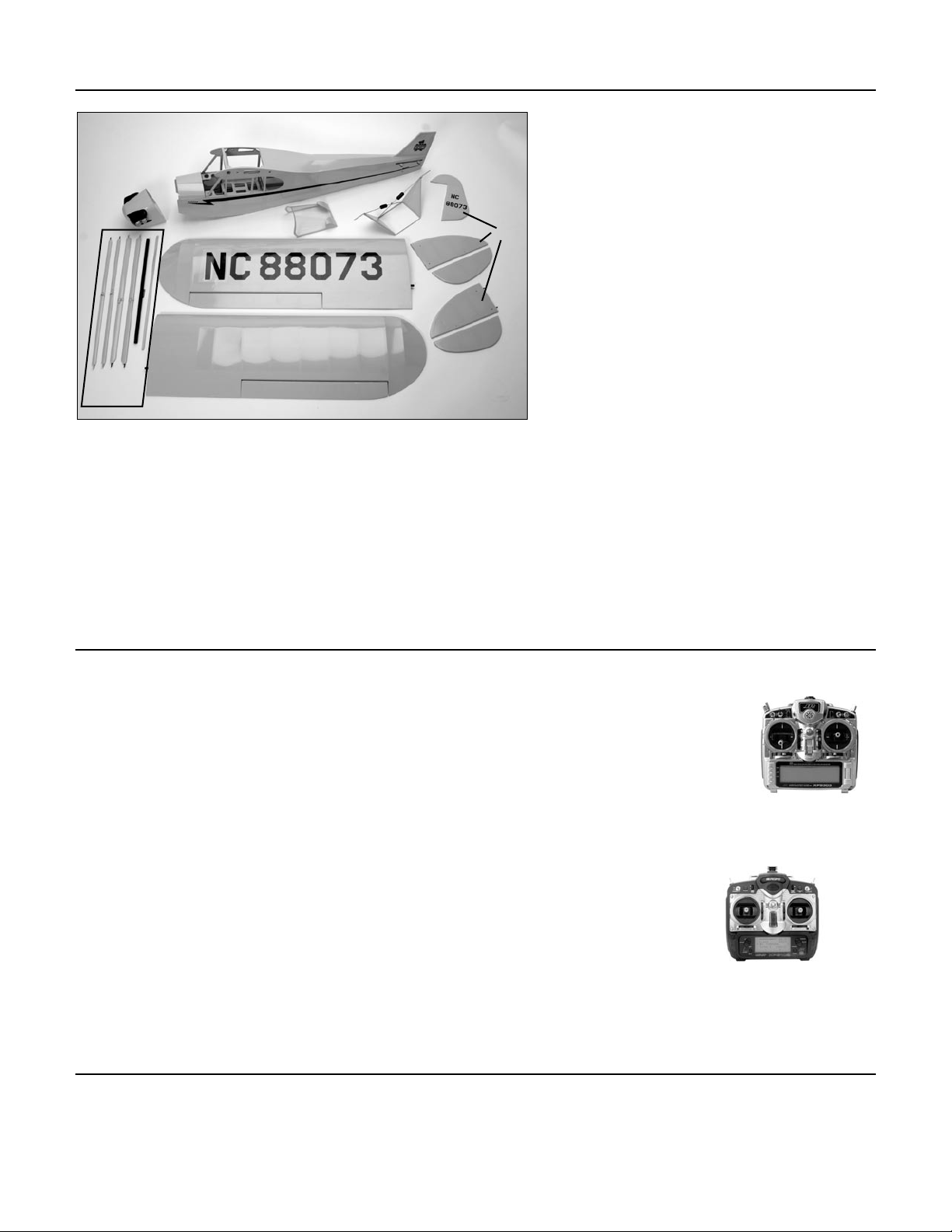
Contents of Kit
A
C
G
F
Large Parts:
A. Fuselage HAN4002
B. Wing HAN4001
E
D
B
C. Cowling HAN4004
D. Tail Set HAN4003
E. Landing Gear HAN4005
F. Wing Strut Set HAN4010
G. Window Set HAN4008
Items Not Shown:
Fuel Tank
Tail Wheel Assembly HAN4007
Decal Set HAN4009
Pushrod Set HAN4011
Wheels HAN4006
Top Fuselage Hatch HAN4012
Additional Required Equipment
Radio Equipment
• 4-channel radio system (minimum)
• 5 standard servos
• Receiver
• Receiver battery
• Switch harness
• 12" Servo Extension (JRPA098) (2)
• “Y” Harness (JRPA135)
• Large Arms/Horns w/Screw (JRPA212)
Recommended JR® Systems
Recommended Engine
Covering Colors
• PCM10X
• XP9303
• XP8103
• X-378
• XP6102
• XF631
• XF421
• Quattro
• Evolution® .36–.46
• Saito™ .56–.82 4-stroke
JR XP9303
JR XP6102
• Cub Yellow HANU884
• Black HANU874
3
Page 4

Additional Required Tools and Adhesives
Tools
• Adjustable wrench
• Crimping tool
• Drill
• Drill bit: 1/16”, 5/64”, 3/32”
• Felt-tipped pen
• Heat gun
• Hobby knife
• Hobby scissors
• Petroleum jelly
• Phillips screwdriver (small)
• Phillips screwdriver (large)
• Pliers
• Rotary tool w/sanding drum
• Ruler
• Sandpaper
• String
• Threadlock
• T-pins
Adhesives
• 6-minute epoxy
• Thin CA
• Medium CA
Other Required Items
• Epoxy brushes
• Felt-tipped pen or pencil
• Measuring device (e.g. ruler, tape measure)
• Mixing sticks for epoxy
• Paper towels
• Petroleum jelly
• Rubbing alcohol
• Sanding bar
• Covering Iron (HAN101)
• Covering Glove (HAN150)
• Sealing Iron Sock (HAN141)
Field Equipment Required
• Propeller
• Fuel
• Glow Plug Wrench (HAN2510)
• Glow Plug Igniter with Charger (HAN7101)
• Glow Plug (HAN3001/3006)
• Manual Fuel Pump (HAN118)
Warning
An RC aircraft is not a toy! If misused, it can cause serious bodily harm and damage to property. Fly only in open areas,
preferably at AMA (Academy of Model Aeronautics) approved flying sites, following all instructions included with your
radio and engine.
4
Page 5
Using the Manual
This manual is divided into sections to help make assembly easier to understand, and to provide breaks between each
major section. Remember to take your time and follow the directions.
Before Starting Assembly
Before beginning the assembly of your J-3 Cub, remove each part from its bag for inspection. Closely inspect the
fuselage, wing panels, rudder, and stabilizer and for damage. If you find any damaged or missing parts, contact the place
of purchase.
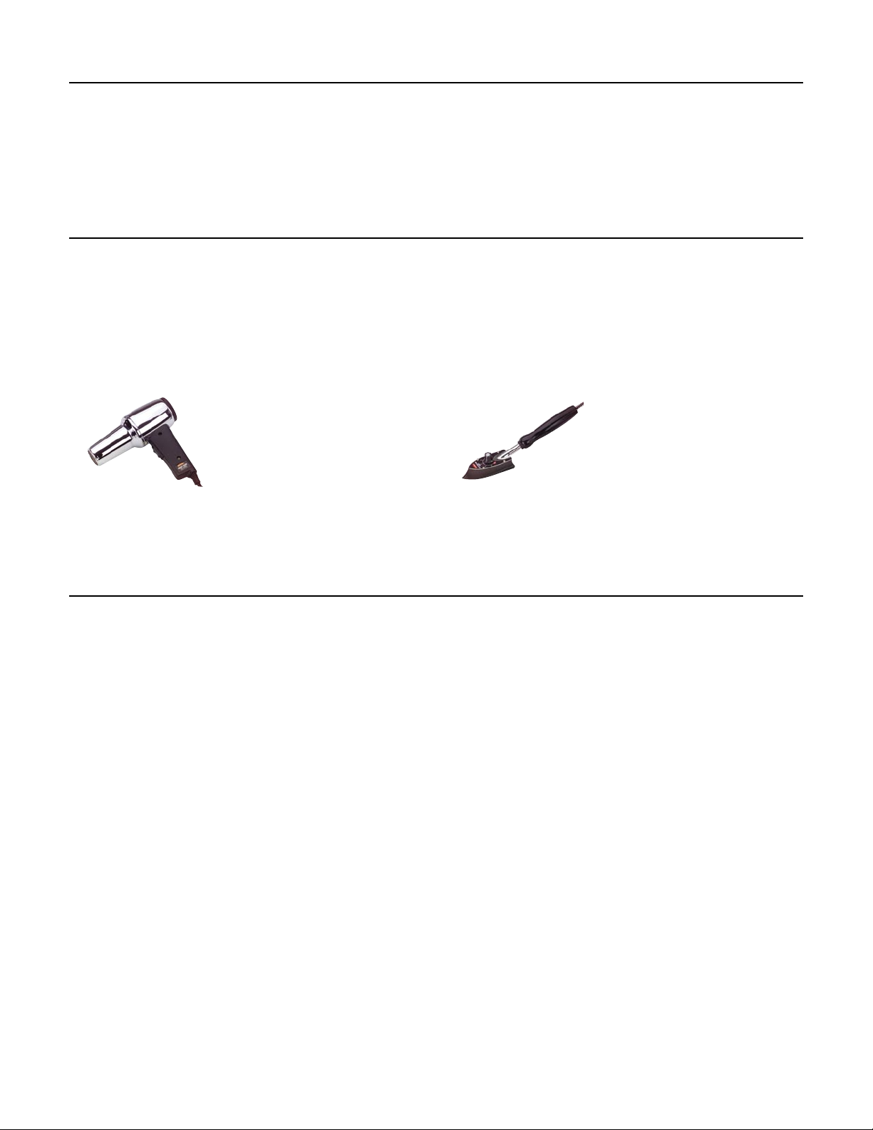
If you find any wrinkles in the covering, use a heat gun or covering iron to remove them. Use caution while working
around areas where the colors overlap to prevent separating the colors.
HAN100 – Heat Gun
HAN150 – Covering Glove
HAN101 – Covering Iron
HAN141 – Sealing Iron
Sock
Warranty Information
Horizon Hobby, Inc. guarantees this kit to be free from defects in both material and workmanship at the date of purchase.
This warranty does not cover any parts damaged by use or modification. In no case shall Horizon Hobby’s liability exceed
the original cost of the purchased kit. Further, Horizon Hobby reserves the right to change or modify this warranty without
notice.
In that Horizon Hobby has no control over the final assembly or material used for the final assembly, no liability shall be
assumed nor accepted for any damage of or caused by the final user-assembled product. By the act of using the product,
the user accepts all resulting liability.
Once assembly of the model has been started, you must contact Horizon Hobby, Inc. directly regarding any warranty
question that you have. Please do not contact your local hobby store regarding warranty issues, even if that is where you
purchased it. This will enable Horizon to better answer your questions and provide service in the event that you may need
any assistance.
If the buyer or user is not prepared to accept the liability associated with the use of this product, they are advised to
return this kit immediately in new and unused condition to the place of purchase.
For any additional questions please contact:
Horizon Hobby Product Support
4105 Fieldstone Road
Champaign, Illinois 61822
(877) 504-0233
www.horizonhobby.com
5
Page 6
Section 1: Hinge Installation
Required Parts
• Stabilizer • Elevator
• Fuselage • Rudder
• Wing • Aileron (R&L)
• Tail gear wire • Hinge (17)
Required Tools and Adhesives
• Thin CA • T-pins
• 6-minute epoxy • Petroleum jelly
• Drill • Drill bit: 1/16", 3/32"
• Hobby knife
Step 1
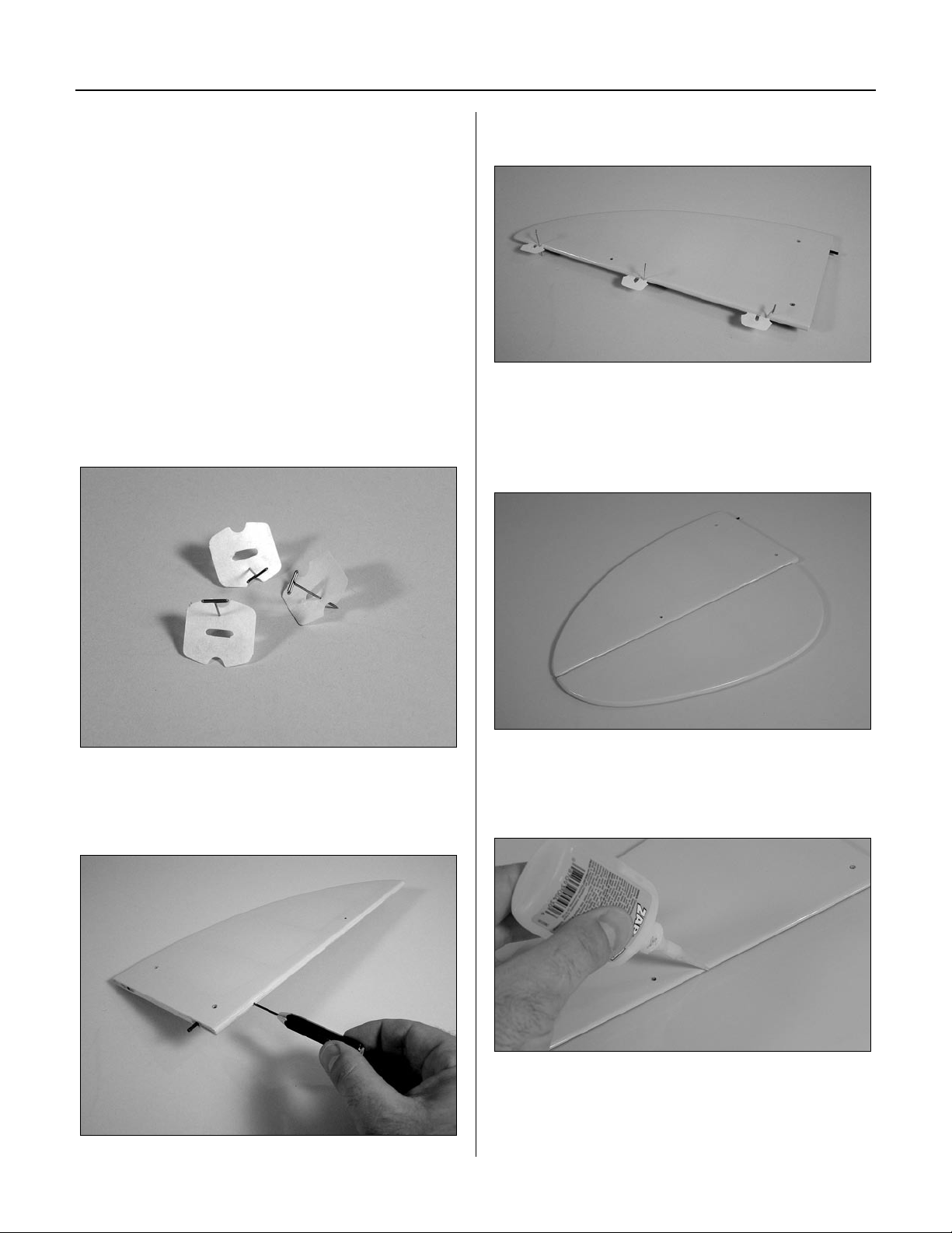
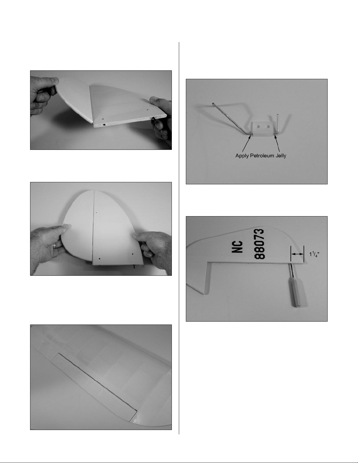
Locate three hinges. Place a T-pin in the center of
each hinge.
Step 3
Place the hinges in the stabilizer.
Step 4
Slide the elevator and stabilizer together. Remove the
T-pins. There should be a 1/64" gap between the
stabilizer and elevator.
Step 2
Drill a 1/16" hole in both a stabilizer and elevator half in
the center of the hinge locations.
6
Step 5
Check that the tips of the stabilizer and elevator are
aligned. Wick thin CA into each of the hinges.
Note: Do not use accelerator in the hinging
process. The CA must be allowed to soak into
the hinge naturally.
Page 7
Section 1: Hinge Installation
Step 6
After the CA has cured, flex the surfaces several times to
break in the hinges.
Step 7
Pull on both surfaces to make sure the hinges are secure.
Step 9
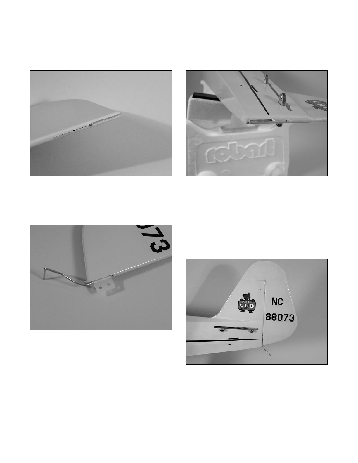
Coat the tail gear wire near the bushing with petroleum
jelly. Work the lubricant into the bearing to prevent epoxy
from entering the bearing, gluing the bearing to the wire.
Step 10
Drill a 3/32" hole in the rudder 1 1/4" from the bottom.
Step 8
Repeat Steps 1 through 7 for the aileron hinges. Each
aileron will use four hinges. Center the ailerons and make
sure they are not binding before gluing the hinges.
7
Page 8
Section 1: Hinge Installation
Step 11
Cut a groove from the hole to the bottom of the rudder to
allow clearance for the tail gear bearing.
Step 12
Apply a thin layer of lubricant where the bearing will
ride in the rudder. Use 6-minute epoxy to glue the wire
into the rudder.
Step 13
Cut a slot in the end of the fuselage to accept the tail
gear bearing.
Step 14
Install three hinges into the rudder. Test fit the rudder
to the fuselage, sliding the hinges and tail wheel bracket
into position.
Step 15
Use 6-minute epoxy to glue the tail gear bearing into the
fuselage. Use thin CA for the hinges.
8
Page 9
Section 2: Engine Installation
Required Parts
• Fuselage assembly • Fuel tank assembly
• Engine mount
• 8-32 x 3/4" bolt (4) • 8-32 X 1" bolt (4)
• 8-32 lock nut (4) • #8 washer (4)
• 14 1/4" pushrod wire • Clevis
• Clevis retainer
• Engine mount plate (2)
Required Tools and Adhesives
• Engine w/muffler • Threadlock
• Ruler • Phillips screwdriver
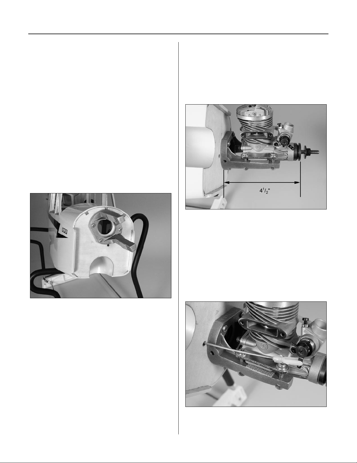
Step 1
Secure the engine mount to the firewall using four
8-32 x 3/4" bolts. Use threadlock to prevent the bolts
from vibrating loose during flight.
Step 2
Position the engine so the drive washer is 4 1/2"
forward of the firewall. Use the engine mount plates,
8-32 x 1" bolts, 8-32 lock nuts and #8 washers to attach
the engine to the mount. The engine mounting lugs are
sandwiched between the engine mount plates and the
engine mount. Tighten the bolts evenly.
Note: The engine mount plates have texture
on one side, which is placed against the
engine mounting lugs.
Step 3
Place a clevis retainer onto a clevis. Thread the clevis
onto the 14 1/4" pushrod wire. Slide the wire into the
pushrod tube in the fuselage. Attach the clevis to the
carburetor arm.
9
Page 10
Section 2: Engine Installation
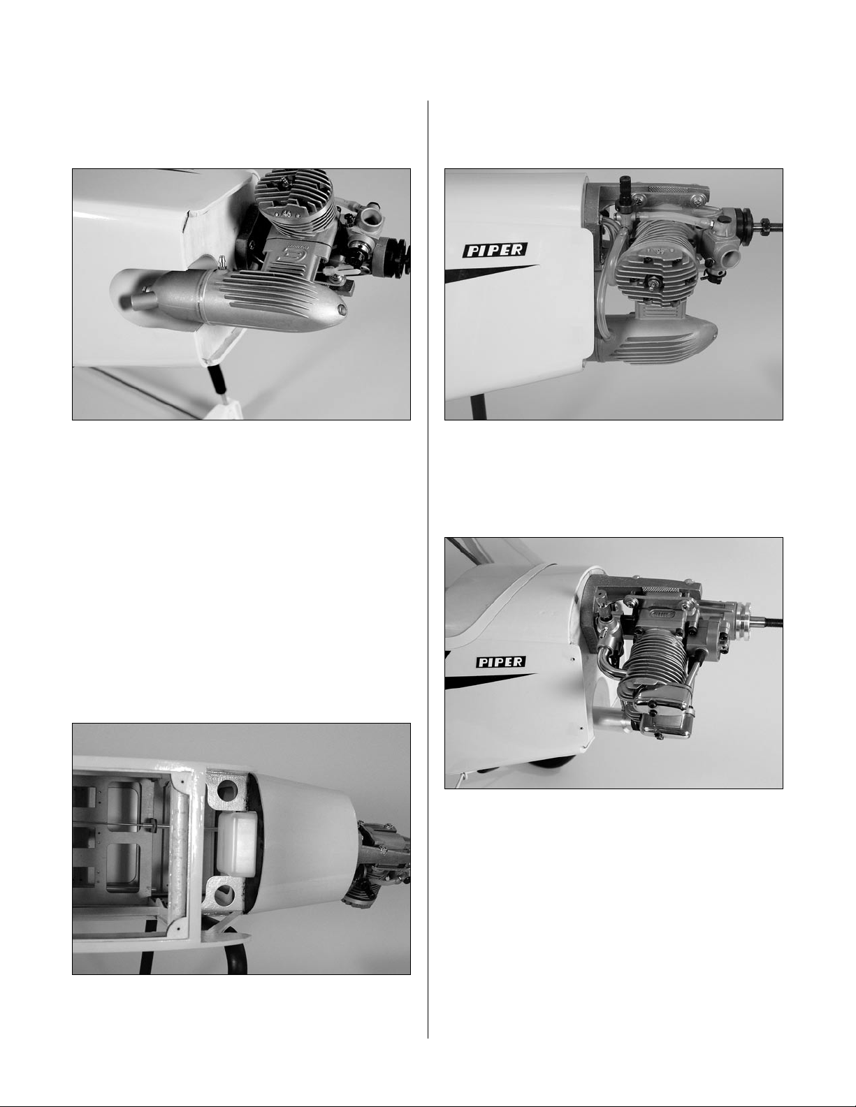
Step 4
Attach the muffler to the engine using the hardware
provided with your particular engine.
Note: It may be necessary to rotate the end of
the muffler to point the stinger straight down,
away from the fuselage.
Step 5
Step 7
Attach the vent line to the muffler and the line from the
clunk to the carburetor.
Step 8
A Saito™ 4-stroke can be installed instead of a 2-stroke
engine. You will have to relocate the throttle pushrod to
line up with the throttle arm on the carburetor.
Check the tank and note which fuel line is vent and which
is attached to the clunk. Make a note of the line colors
and which they correspond to. Also note the direction
of the vent line inside the fuel tank so it faces toward the
top of the fuselage.
Step 6
With the vent line up, slide the fuel tank into the fuselage.
10
Page 11
Section 3: Servo Installation (Aileron)
Required Parts
• Wing (L&R) • Servo hatch (L&R)
• #2 x 3/8" screw (8) • Control horn (2)
• 2mm x 20mm screw (6) • Clevis (2)
• Clevis retainer (2)
• 4 3/4" pushrod wire (2)
• Pushrod wire keeper (2)
Required Tools and Adhesives
• Phillips screwdriver (small) • 6-minute epoxy
• Felt-tipped pen • String
• Drill • Drill bit: 1/16", 3/32"
• Pliers • “Y” harness
• 12" servo extension (2) • Hobby knife
• Long Servo Arm (JRPA212) (2)
Step 1
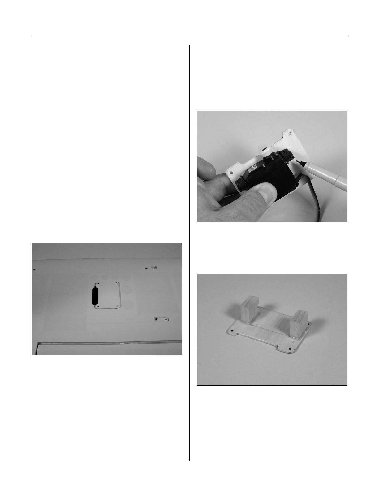
Remove the covering from the servo opening in the
bottom of the wing using a hobby knife. Select the correct
servo hatch by checking the alignment for the servo arm
on the plate with the one on the wing.
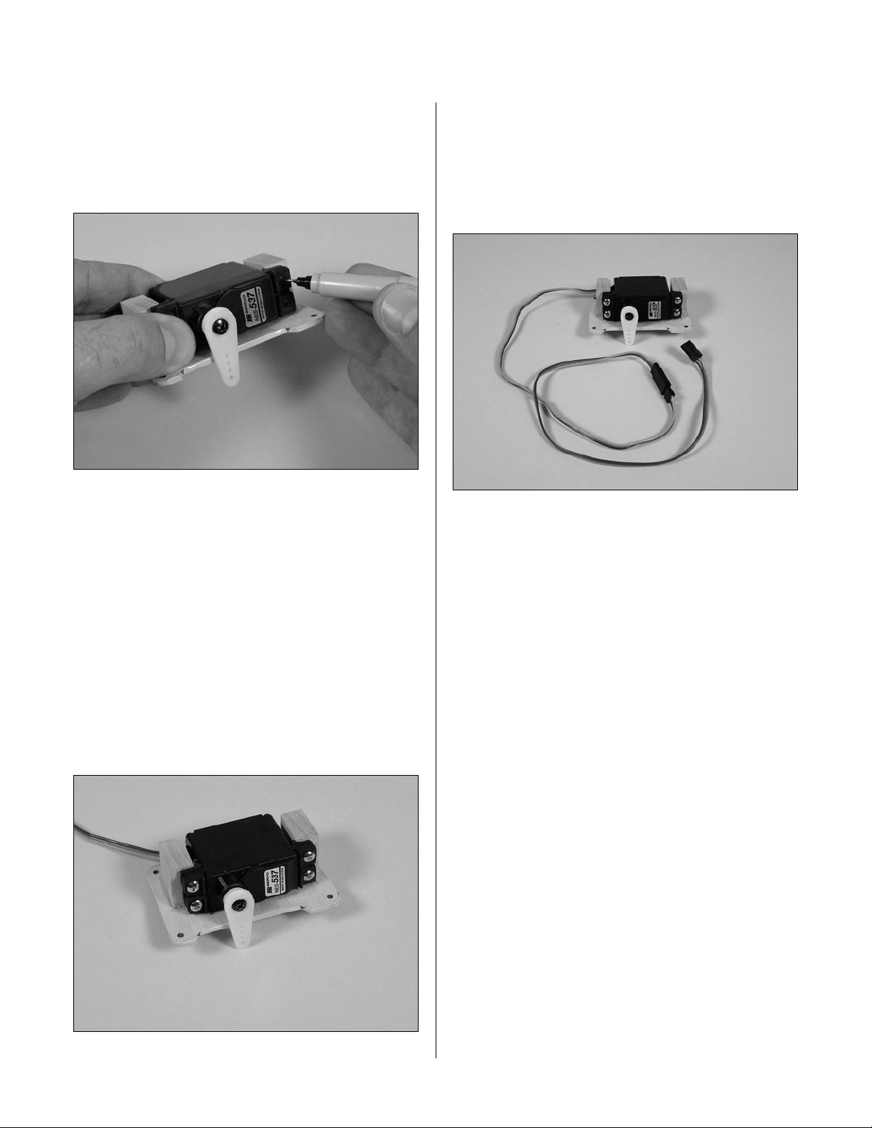
Step 2
Install the recommended servo hardware (grommets and
eyelets) supplied with the servo. Temporarily install a long
half servo arm (JRPA212) onto the servo and position
the servo onto the hatch so the servo arm is centered in
the notch. Once satisfied, mark the location for the servo
mounting blocks using a felt-tipped pen.
Step 3
Locate the 3/8" x 3/4" x 3/4" servo mounting blocks.
Use 6-minute epoxy to glue the blocks to the hatch. Let
the epoxy fully cure before proceeding to the next step.
11
Page 12
Section 3: Servo Installation (Aileron)
Step 4
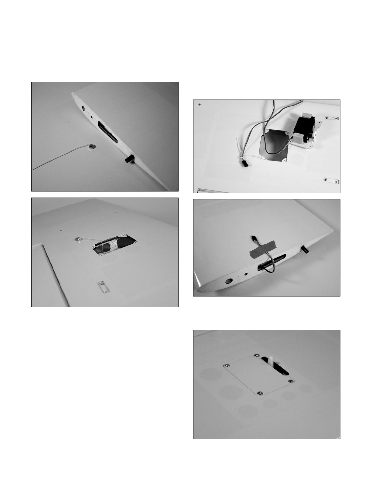
Place the aileron servo between the mounting blocks and
use a felt-tipped pen to mark the location of the four servo
mounting screws. Note that the servo must not touch the
hatch in order to isolate engine vibration.
Note: Before mounting the servo,
electronically center the servo using the
transmitter, then install the servo arm to
avoid having to remove the servo and center
the arm later. It may be necessary to slightly
trim one of the servo mounting blocks to clear
the servo wire.
Step 6
Connect a 12" Servo Lead Extension (JRPA098) to the
servo lead. Secure the connectors by tying them in
a knot using dental floss or by using a commercially
available connector clamp to prevent the servo leads from
becoming disconnected.
Note: It is always a good idea to secure
the servo connector and servo extension
together to prevent the wires from
becoming unplugged.
Step 5
Remove the servo and use a 1/16" drill bit to pre-drill
the holes for the servo mounting screws marked in the
previous step. Use the screws supplied with the servo to
mount it to the servo mounting blocks.
12
Page 13
Section 3: Servo Installation (Aileron)
Step 7
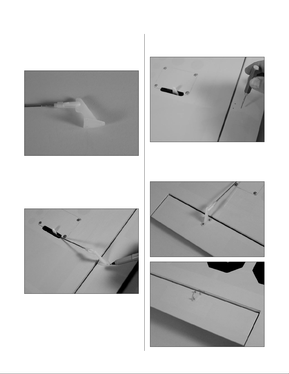
Tie a wheel collar onto a piece of string. Drop the wheel
collar into the wing from the root and retrieve it from the
servo opening.
Step 8
Tie the string onto the servo extension. Gently pull the
extension through the wing using the string. Untie the
string when the servo lead has been pulled through. Use
tape to secure the servo lead to the wing to prevent it from
falling back into the wing panel.
Step 9
Secure the hatch using four #2 x 3/8" screws.
13
Page 14
Section 3: Servo Installation (Aileron)
Step 10
Place a clevis retainer onto a clevis. Thread the clevis
onto a 4 3/4" pushrod wire. Remove the backplate
from a control horn, and then attach the clevis to the
control horn.
Step 11
Position the control horn on the aileron. Use the
pushrod wire as a guide to align the horn to the servo
arm. Position the horn so the holes align with the hinge
line. Use a felt-tipped pen to mark the positions for the
three mounting bolts.
Step 12
Drill the locations marked in the previous step using
a 3/32" drill bit.
Step 13
Place a few drops of thin CA into each of the holes to
harden the balsa. Attach the control horn using three
2mm x 20mm screws and the control horn backplate.
14
Page 15
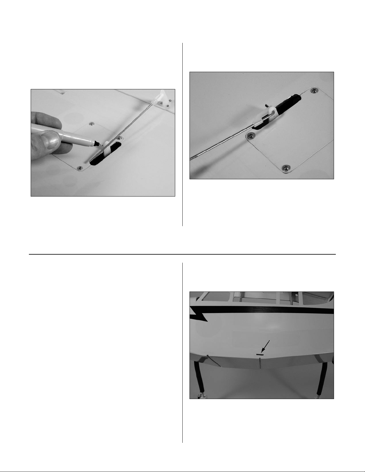
Section 3: Servo Installation (Aileron)
Step 14
Plug in the aileron servo to the radio system. Center the
trims on the transmitter to center the aileron servo. Hold
the aileron in neutral. Use a felt-tipped pen to mark the
pushrod wire where it crosses the servo arm.
Step 15
Bend the pushrod wire at the mark. Use a pushrod wire
keeper to secure the pushrod wire to the servo arm.
Step 16
Repeat Steps 1 though 15 for the remaining wing panel.
Section 4: Servo Installation (Fuselage)
Required Parts
• Fuselage • Clevis
• Clevis retainer • Control horn
• Wing strut mount (2) • #4 x 3/8" screw (4)
• 19 3/4" pushrod dowel • 6" pushrod wire
• Pushrod wire (32”)
• 2 1/8" heat shrink tubing (2)
• 2mm x 12mm screw (3)
• 7 1/4" pushrod wire (2)
Required Tools and Adhesives
• Phillips screwdriver • Hobby knife
• Drill • Drill bit: 3/32", 5/64"
• Heat gun • Medium CA
• Thin CA • Felt-tipped pen
Step 1
Remove the covering for the wing strut mount. The
opening is located above the rear landing gear mount.
15
Page 16
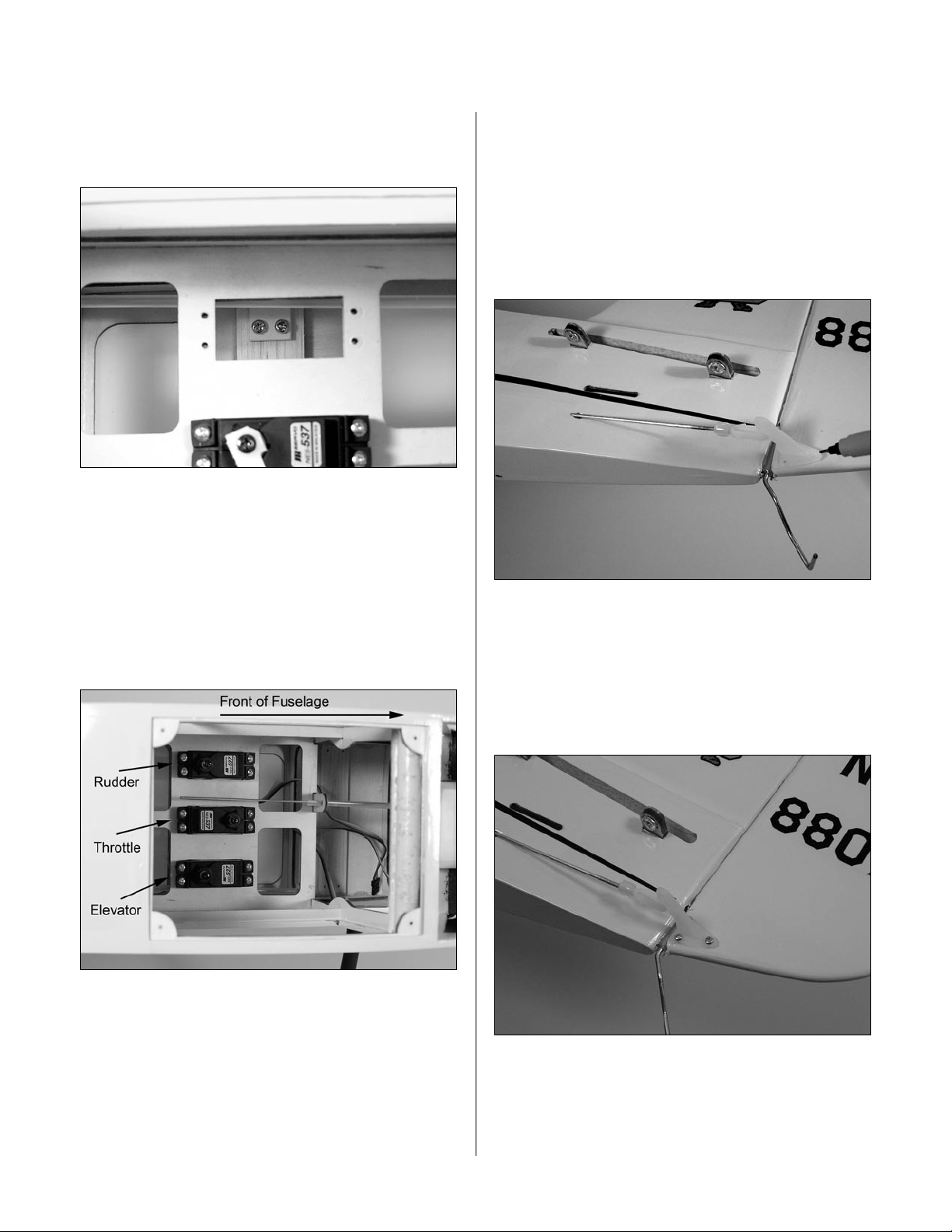
Section 4: Servo Installation (Fuselage)
Step 2
Slide the wing strut mount into the opening. Secure the
mount using two #4 x 3/8" screws.
Step 3
Install the recommended servo hardware (grommets and
eyelets) supplied with the servos into the throttle, rudder,
and elevator servos.
Step 5
Place a clevis retainer onto a clevis. Thread the clevis
onto a 32" pushrod wire. Remove the backplate from a
control horn, and then attach the clevis to the control
horn. Slide the pushrod into the rudder pushrod tube in
the fuselage. Position the horn so the holes align with the
hinge line. Use a felt-tipped pen to mark the positions for
the three mounting bolts.
Step 4
Use the hardware provided with the servos to mount them
in the fuselage.
Step 6
Drill the locations marked in the previous step using
a 3/32" drill bit. Place a few drops of thin CA into
each of the holes to harden the balsa. Attach the control
horn using three 2mm x 12mm screws and the control
horn backplate.
16
Page 17
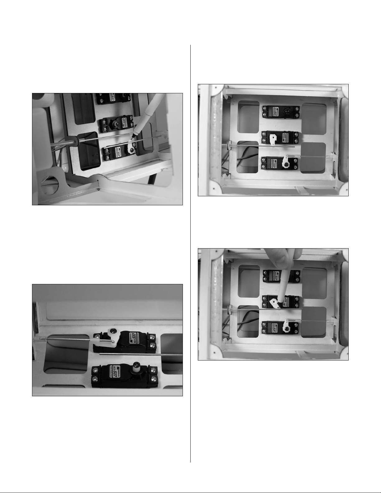
Section 4: Servo Installation (Fuselage)
Step 7
Plug in the rudder servo to the radio system. Center the
trims on the transmitter to center the rudder servo. Hold
the rudder in neutral. Use a felt-tipped pen to mark the
pushrod wire where it crosses the servo arm.
Step 8
Remove the pushrod wire from the fuselage and remove
the clevis. Bend the pushrod wire at the mark. Slide
the pushrod back into the fuselage from the radio
compartment, and then put the clevis back onto the
wire. Use a pushrod wire keeper to secure the pushrod
wire to the servo arm.
Step 9
Center the throttle stick and trim with both the receiver
and transmitter on. Install the throttle servo arm in the
neutral position.
Step 10
Move the throttle stick and trim lever down to the throttle
closed position. Manually close the carburetor and mark
the throttle pushrod where it crosses the servo arm.
17
Page 18
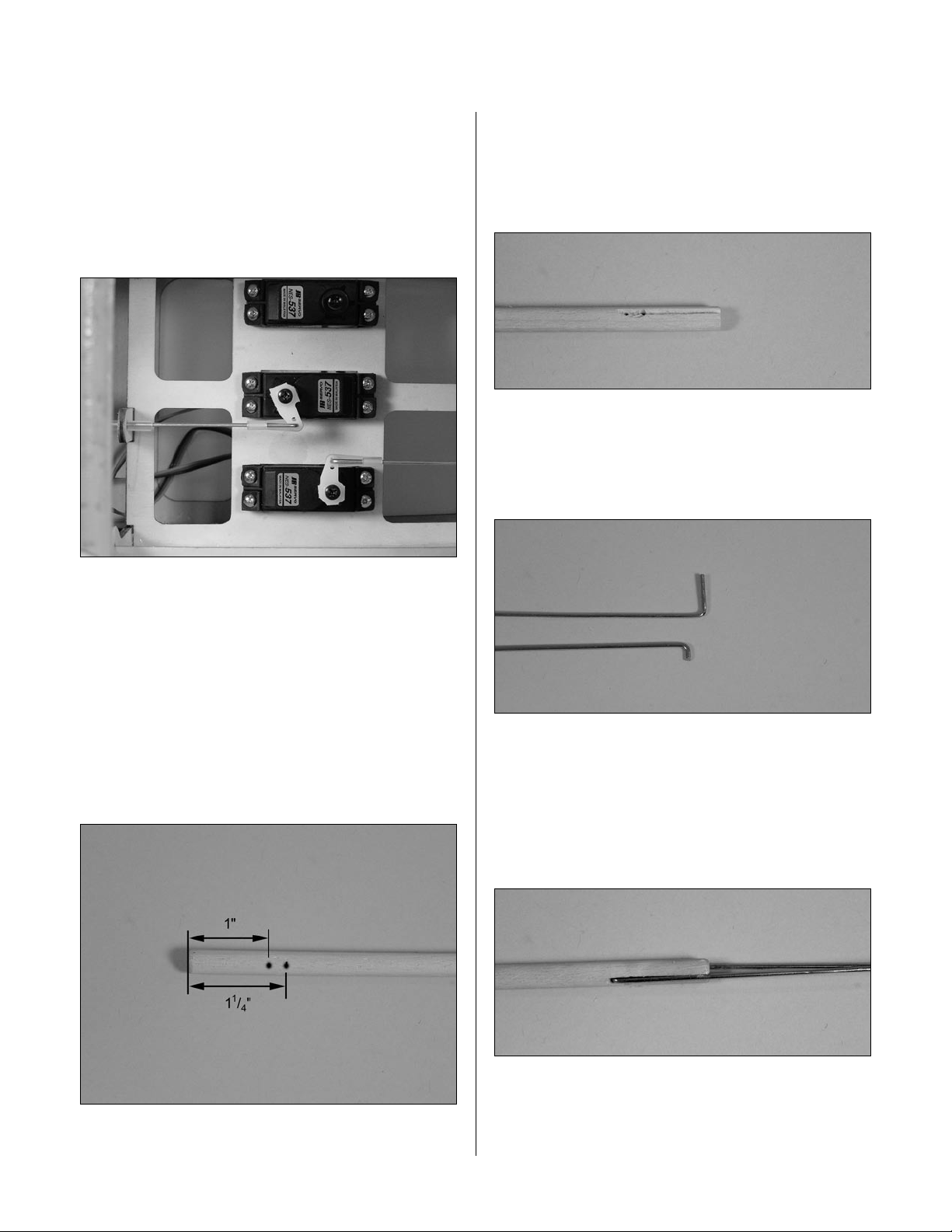
Section 4: Servo Installation (Fuselage)
Step 11
Remove the pushrod wire from the fuselage and remove
the clevis. Bend the pushrod wire at the mark. Slide
the pushrod back into the fuselage from the radio
compartment, and then put the clevis back onto the
wire. Use a pushrod wire keeper to secure the pushrod
wire to the servo arm.
Step 14
Cut a groove into the pushrod from the hole to the end
of the pushrod. Repeat for the opposite side so you end
up with two grooves. The elevator pushrod wires will
rest in these grooves.
Step 15
Locate the two 7 1/4" pushrod wires. Make a bend in one
wire 1/4" from the non-threaded end of one of the wires.
The remaining pushrod is bent 1/2" from the end.
Step 12
Check the movement of the throttle to verify there is no
binding at either low or high throttle. If there is, make the
necessary adjustment to eliminate any binding. Install the
throttle servo arm screw when complete.
Step 13
Locate the 19 3/4" wood pushrod for the elevator. Drill two
5/64" holes through the dowel, 1" and 1 1/4", from one
end. The holes must be parallel to each other.
Step 16
Test fit the two wires. The wire bent at 1/2" is placed in
the hole closest to the pushrod end. You will have to
trim the wire down after the bend so it won’t interfere
with the other pushrod. Once fit, use medium CA to
glue the wires to the dowel.
18
Page 19
Section 4: Servo Installation (Fuselage)
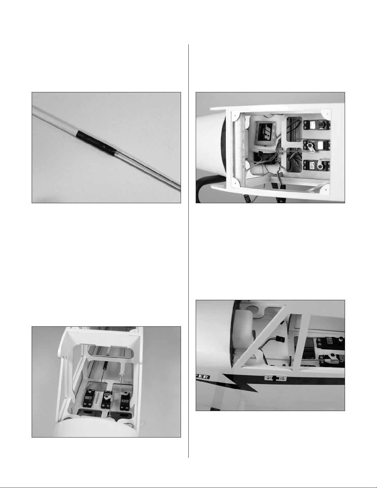
Step 17
Slide the 2 1/8" piece of heat shrink over the wires and
dowel. Use a heat gun or lighter to shrink the tubing. Once
the tubing has been shrunk, apply thin CA to each end of
the shrink to complete this part of the pushrod assembly.
Step 18
Repeat Steps 13 through 17 for the opposite end of
the dowel, but only drill one hole and prepare one 6"
pushrod wire.
Step 19
Slide the elevator pushrod wire in position into the
fuselage. It may take some time to get it in, so be
patient. Slide a clevis retainer onto two clevises, and
then thread them onto the pushrod wires at the aft end
of the fuselage. This will prevent the pushrod wire from
falling out of the fuselage.
Step 20
Plug the necessary servo leads into the receiver. This
includes the switch harness and battery leads as well.
Install the flat radio foam into the fuselage, followed by the
die-cut foam. Place the receiver and battery into the foam.
Note: There is a tube located under the
elevator servo for the antenna wire. Route the
wire through this tube to the tail of the aircraft.
Step 21
Place the remaining flat radio foam over the receiver and
battery. Secure the foam to prevent the receiver and battery
from moving from their location. Mount the receiver
switch to the side of the fuselage.
19
Page 20

Section 5: Window Installation
Required Parts
• Side window (L&R) • Front windscreen
• Support (2) • Fuselage hatch
Required Tools and Adhesives
• Hobby scissors • Canopy glue
• Hobby knife
Step 1
Use hobby scissors and a hobby knife to trim the side
windows from their sheets. Leave a 1/8" lip to glue the
windows to the fuselage.
Step 3
Cut and fit the two supports to the fuselage. Use medium
CA to glue them into position.
Step 4
Test fit the front windscreen into position. Trim as
necessary. Use canopy glue to secure the front
windscreen to the fuselage.
Step 2
Test fit the windows from the inside of the fuselage. Trim
them as necessary so they fit flush to the outside of the
fuselage. Use canopy glue to secure the windows into the
fuselage. Install the window into the fuselage hatch at this
time as well.
Note: You can use epoxy as well, but be
very careful not to get epoxy on the nice clear
windows.
20
Page 21
Section 6: Landing Gear Installation
Required Parts
• Landing gear
• 3.35" (85mm) wheel (2) • Wheel cap (2)
• Inner wheel hub (2) • Outer wheel hub (2)
• 1" (25mm) wheel • Landing gear strap (4)
• 2mm x 14mm screw (8)
• Large wheel collar w/setscrew (4)
• 3mm x 10mm screw (8)
• Small wheel collar w/setscrew
Required Tools and Adhesives
• Phillips screwdriver (small) • Hex wrench
• Hobby knife • Sandpaper
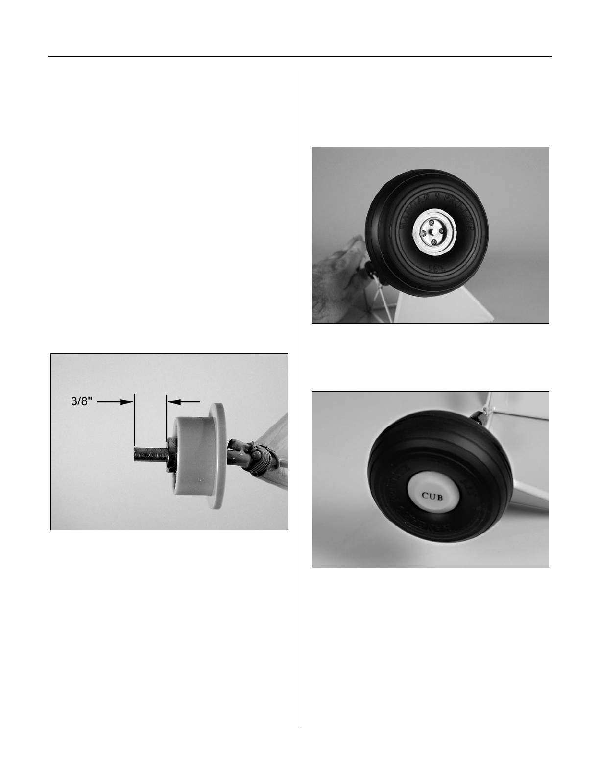
Step 1
Use a hobby knife to scrape away the paint on the landing
gear where the wheel will be located. Slide the inner wheel
hub onto the axle. Next, slide a large wheel collar 3/8"
from the end of the axle and secure it using the setscrew.
Step 2
Position the 3.35" (85mm) wheel onto the inner hub.
Attach the outer wheel hub to the inner wheel hub using
four 2mm x 14mm screws. The screws go through the
outer wheel hub and into the inner wheel hub.
Step 3
Snap the wheel cap onto the wheel.
Step 4
Repeat Steps 1 through 3 for the remaining wheel.
21
Page 22
Section 6: Landing Gear Installation
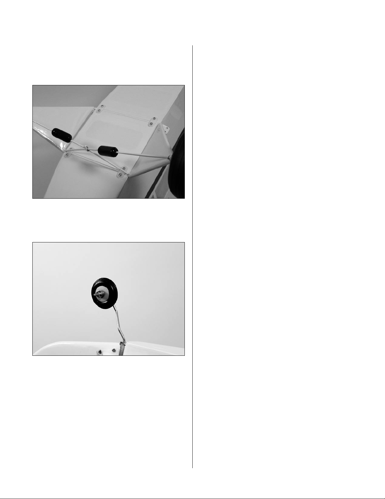
Step 5
Position the landing gear to the bottom of the fuselage.
Secure the position of the gear using four landing gear
straps and eight 3mm x 10mm screws.
Step 6
Secure the tail wheel using the small wheel collar
and setscrew.
22
Page 23
Section 7: Installing the Stabilizer
Required Parts
• Stabilizer assembly • Fuselage
• #4 washer (4) • #2 washer (3)
• 2-56 x 1/2" screw (3) • 2-56 nut (3)
• Clevis (4) • Clevis retainer (4)
• Cable ends (4) • Brass crimps (8)
• Cable • Pushrod wire keeper
• Control horn (2)
• 2mm x 12mm screw (6)
• Brass fitting (small) (6)
• Brass fitting (large) (2)
• #2 x 1/2" sheet metal screw
• 4-40 x 1/2" socket head screw (4)
Required Tools and Adhesives
• Threadlock • Pliers
• Drill • Drill bit: 3/32"
• Adjustable wrench • Crimping tool
• Phillips screwdriver (small)
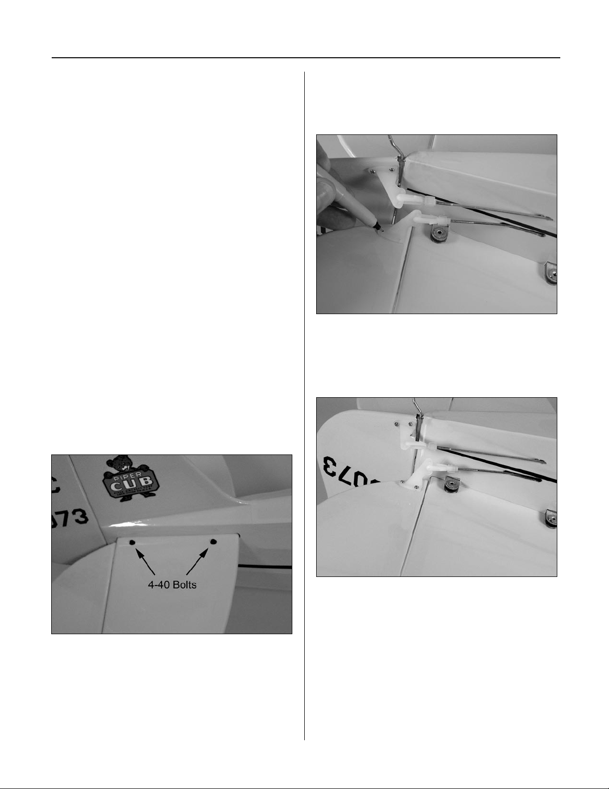
Step 1
Slide the stabilizer halves into the slot in the fuselage.
Use four 4-40 x 1/2" screws and four #4 washers to
secure the stabilizer. Use threadlock to prevent the
screws from vibrating loose during flight.
Step 2
Attach a control horn to one of the elevator clevises. Line
the holes in the control horn with the hinge line and mark
the location for the mounting crews onto the elevator.
Step 3
Drill the holes using a 3/32" drill bit. Use thin CA to
harden the holes. Mount the control horn using the horn
backplate and three 2mm x 12mm screws.
23
Page 24
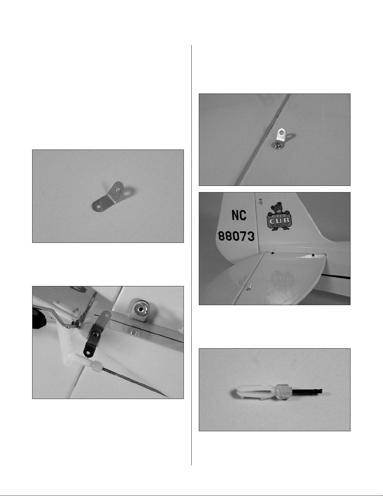
Section 7: Installing the Stabilizer
Step 4
Repeat Steps 2 and 3 for the remaining elevator
control horn.
Step 5
Attach the elevator pushrod to the servo arm of the
elevator servo using a pushrod wire keeper.
Step 6
Bend each of the fittings (small and large) to about a
45-degree angle.
Step 8
Attach the small brass fitting to the fin and stabilizer
using 2-56 x 1/2" screws, #2 washers and 2-56 nuts.
Fittings are placed on both sides of the rudder and
the top and bottom of the stabilizer.
Step 7
Attach the large brass fittings at the bottom rear of the
fuselage using the #2 x 1/2" sheet metal screw.
Step 9
Slide a clevis retainer onto a clevis. Thread a cable end
into the clevis. Prepare four of these connectors.
24
Page 25
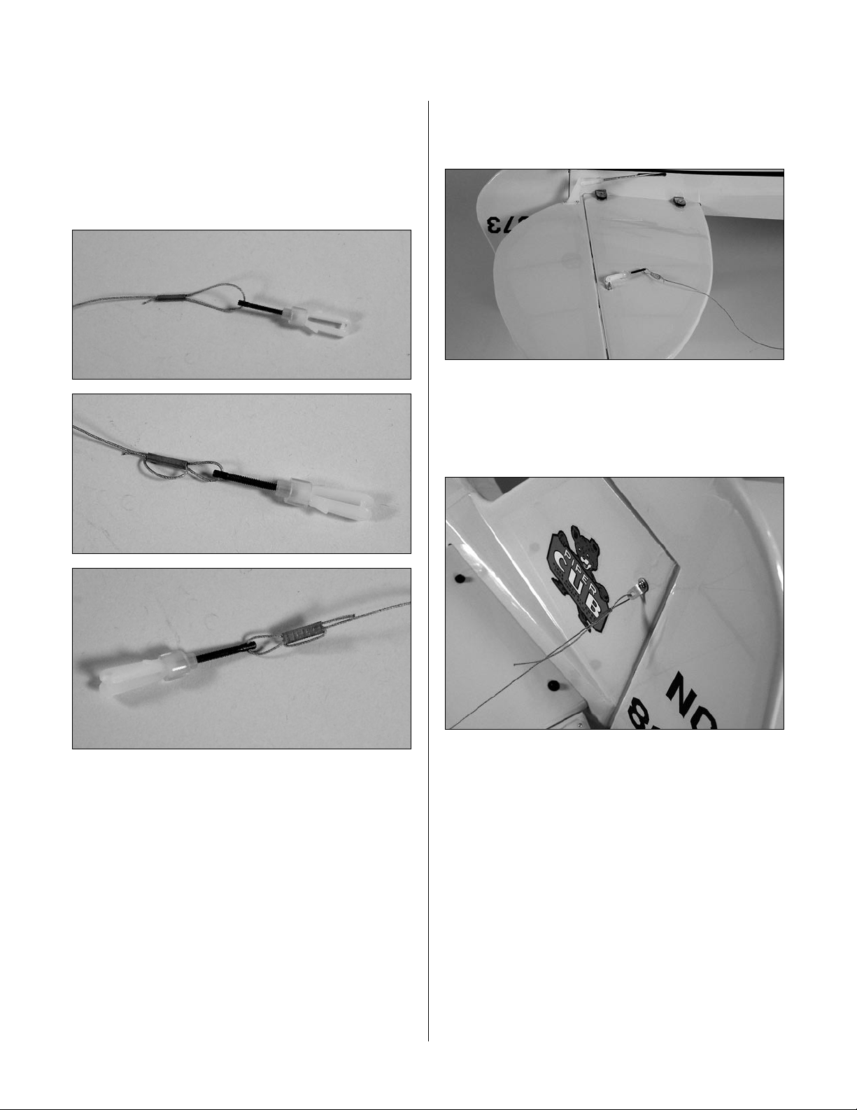
Section 7: Installing the Stabilizer
Step 10
Cut the cable into four equal pieces. Prepare one cable by
sliding the cable through a crimp, through the cable end,
then back through the crimp twice. Pull the excess cable
tight and use a crimping tool to complete the job. Repeat
for all four of the ends.
Step 11
Attach the four connectors to the brass fittings
of the stabilizer.
Step 12
Repeat Step 10, only passing the cable through the brass
fittings instead of the cable ends. The cables should have
very light tension.
25
Page 26

Section 8: Cowling Installation
Required Parts
• Fuselage • Propeller
• #2 x 3/8" sheet metal screw (4)
Required Tools and Adhesives
• Phillips screwdriver (small) • Ruler
• Drill • Drill bit: 1/16", 5/64"
• Hobby scissors • Felt-tipped pen
• Rotary tool w/sanding drum
Step 1
Remove the propeller nut and washer from the engine.
Position the drive washer so it is keyed onto the engine
shaft. Slide the spinner backplate onto the engine shaft,
and then slide the propeller into position.
Step 2
Use card stock taped to the fuselage to indicate the
locations for the needle valve, cylinder head, muffler, and
any other items that will extend outside the cowling.
Step 3
Remove the engine and slide the cowling onto the
fuselage. Position it so the opening for the crankshaft is
4 1/8" forward of the firewall. Transfer the locations from
the card stock onto the cowling using a felt-tipped pen.
Step 4
Carefully trim the cowling to fit over the engine. Work
slowly and remove small amounts of material at a time.
Use card stock to indicate the sides of the fuselage.
Slide the cowl in position, allowing the drive washer to
extend 1/8" forward of the cowl, then mark the positions
for the cowling screws.
26
Page 27
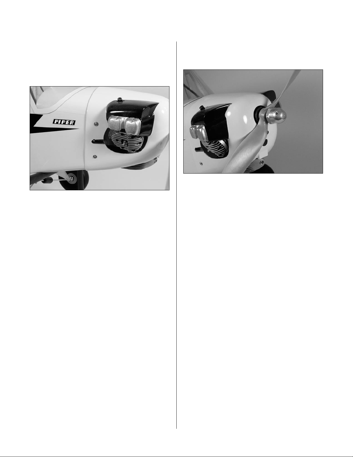
Section 8: Cowling Installation
Step 5
Drill 1/16" holes through the cowl and into the fuselage
sides at the locations marked in the last step. Enlarge the
holes in the cowl using a 5/64" drill bit. Secure the cowl
to the fuselage using four #2 x 3/8" screws.
Step 6
Attach the propeller following the instructions provided
with your particular engine.
27
Page 28
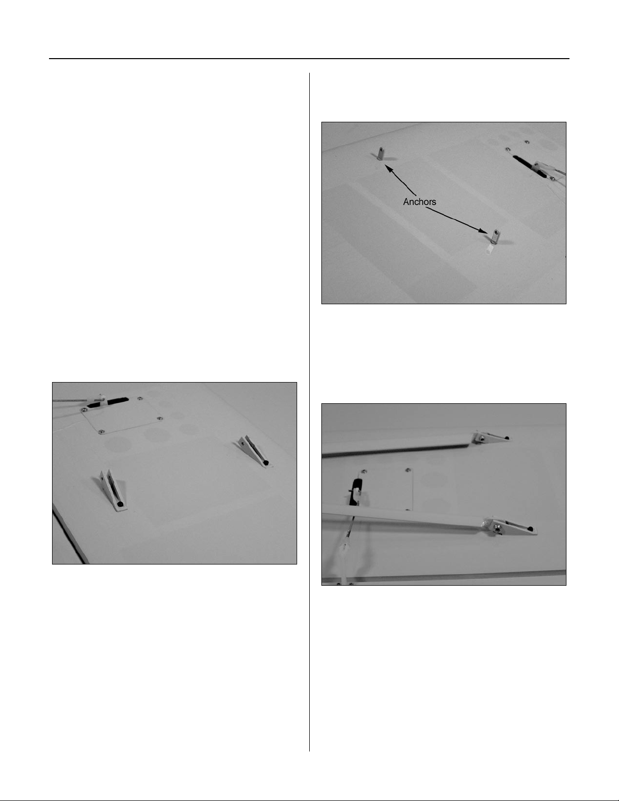
Section 9: Wing Installation
Required Parts
• Wing • Fuselage
• 4-40 lock nut (16) • 4-40 nut (4)
• Strut support anchor (4) • Strut bracket (4)
• Strut end (4) • Strut (narrow) (L&R)
• Strut (wide) (L&R) • Strut brace (long) 2
• Strut brace (short) (2) • Strut cross brace (2)
• #2 x 3/8" screw (4) • Fuselage hatch
• 1/4-20 x 2" nylon bolt (2)
• 4-40 x 1/2" socket head screw (24)
Required Tools and Adhesives
• Hex wrench • Adjustable wrench
• Threadlock
• Phillips screwdriver (small)
Step 1
Attach two strut brackets to the bottom of the wing using
four 4-40 x 1/2" socket head screws. Use threadlock to
prevent the screws from loosening during flight.
Step 2
Thread the strut support anchors into the holes in the
wing. The anchors have external threads.
Step 3
Attach the strut to the strut brackets using two 4-40 x 1/2"
socket head screws and two 4-40 lock nuts. The wide strut
goes towards the leading edge, the narrow strut towards
the trailing edge.
28
Note: The airfoil of the struts matches the
direction of the wing. The struts also have
fittings in the center, which will face towards
the wing when installed.
Page 29
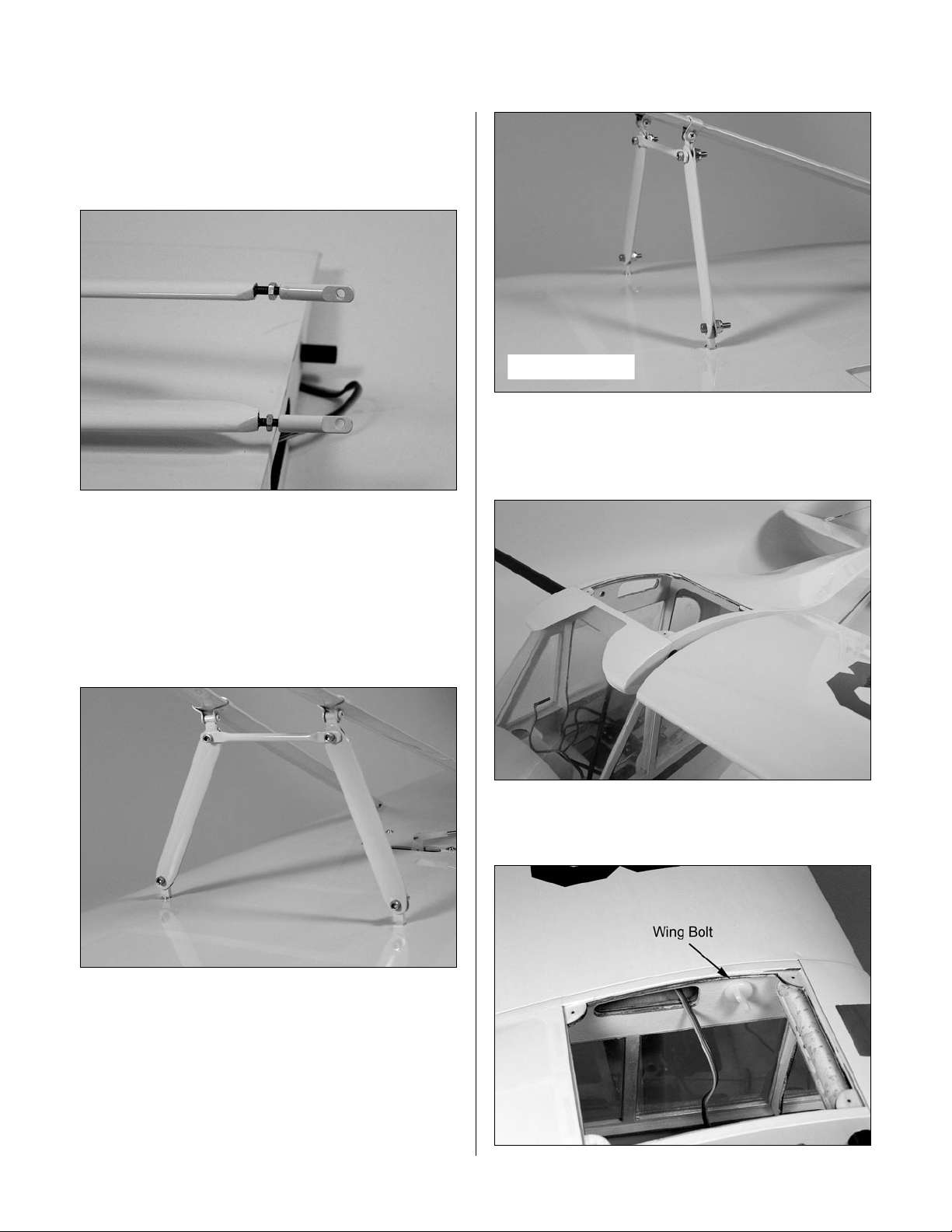
Step 4
Thread a 4-40 nut onto the threaded end of the strut.
Thread a strut end onto the strut. The nut will be used
once the strut has been adjusted.
Section 9: Wing Installation
Step 5 Photo
Step 6
Slide the wing tube into the wing panel. Slide the tube and
panel into position on the fuselage.
Step 5
Install the short strut brace to the rear strut support
anchor and the long strut brace to the front strut support
anchor using 4-40 x 1/2" socket head screws and
4-40 nuts. Attach the strut supports and the strut cross
brace using two 4-40 x 1/2" socket head screws and
two 4-40 lock nuts.
Step 7
Secure the wing panel using a 1/4-20 x 2" nylon bolt.
29
Page 30
Section 9: Wing Installation
Step 8
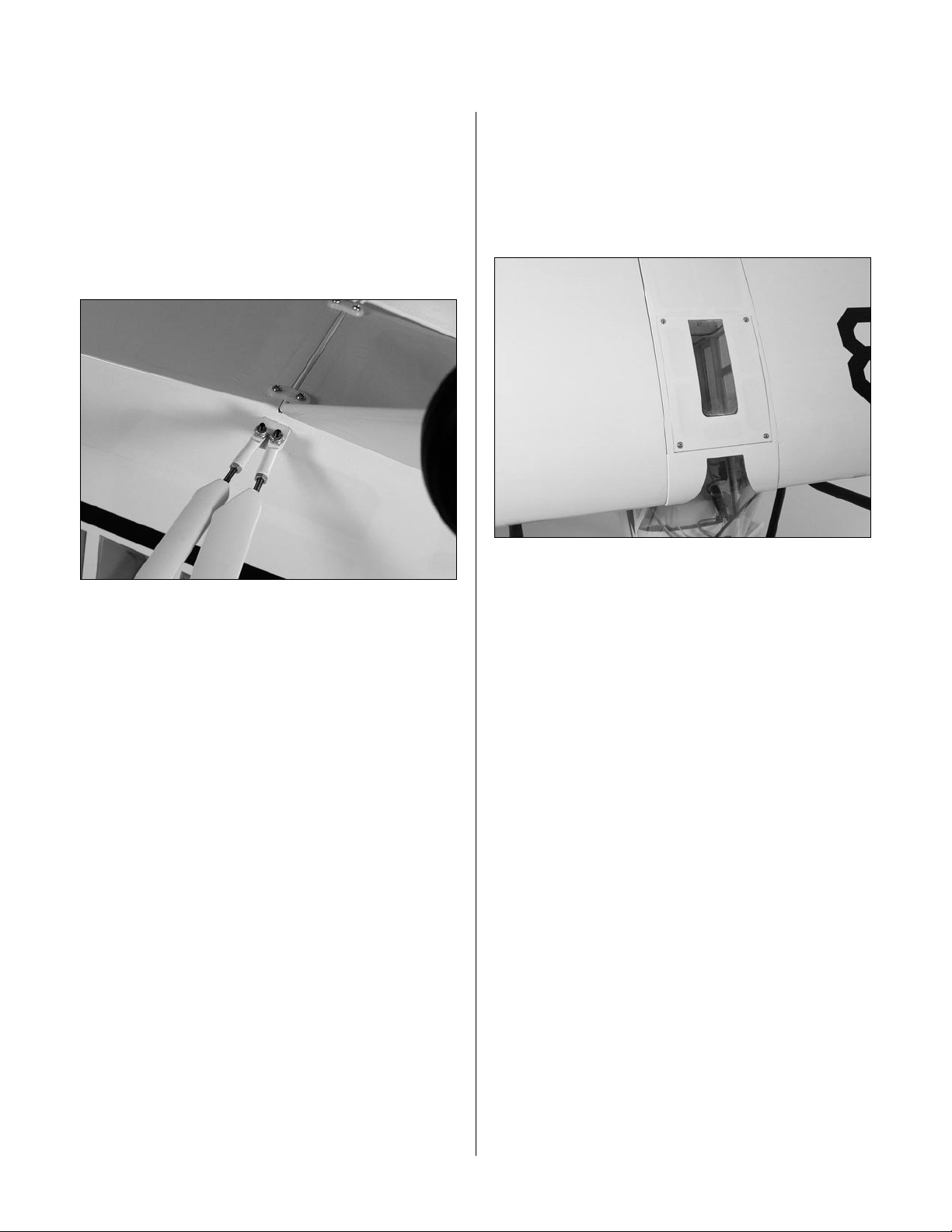
Support the fuselage so the wing is not resting on the
work surface. Adjust the strut end so it aligns with the
wing strut mount. Attach the wing struts using two
4-40 x 1/2" socket head bolts and two 4-40 locking
nuts. Once attached, tighten the 4-40 nuts on the strut to
prevent the end from rotating when the wing is removed
for storage.
Step 9
Repeat Steps 1 through 8 to install the remaining wing
panel and strut.
Step 10
Install the fuselage hatch using four #2 x 3/8" screws.
Note: When removing the wing, simply
disconnect the bolts holding the strut to the
fuselage. This will make things much easier
when installing the wing at the field.
Note: The struts on the J-3 Cub are
functional, so be sure all bolts and nuts
are tight before flying. Failure to do so
could result in wing failure.
30
Page 31

Adjusting the Engine
Step 1
Completely read the instructions included with your
engine and follow the recommended break-in procedure.
Step 2
At the field, adjust the engine to a slightly rich setting at
full throttle and adjust the idle and low-speed needle so
that a consistent idle is achieved.
Control Throws
The amount of control throw should be adjusted as closely
as possible using mechanical means, rather than making
large changes electronically at the radio. By moving
the position of the clevis at the control horn toward the
outermost hole, you will decrease the amount of control
throw of the control surface. Moving it toward the control
surface will increase the amount of throw. Moving the
pushrod wire at the servo arm will have the opposite
effect: Moving it closer to center will decrease throw,
and away from center will increase throw. Work with a
combination of the two to achieve the closest or exact
control throws listed.
Elevator
Step 3
Before you fly, be sure that your engine idles reliably,
transitions and runs at all throttle settings. Only
when this is achieved should any plane be considered
ready for flight.
Aileron
Low Rate
3/8" (8º) Up 1/2" (9º) Down
High Rate
7/8" (21º) Up 11/16" (22º) Down
Linear measurement (inches) measured at root.
Rudder
11/2" (28º) Left 11/2" (28º) Right
Linear measurement (inches) measured at front
of counterbalance.
Low Rate
11/16" (11.5º) Up 9/16" (10º) Down
High Rate
11/4" (19.5º) Up 1" (18º) Down
Linear measurement (Inches) measured at
widest part of elevator (roughly in the center).
Note: Use the Low Rate for most flying. The
High Rate is used specifically for performing
spin maneuvers.
31
Page 32

Recommended CG
An important part of preparing the aircraft for flight is
properly balancing the model. This is especially important
when various engines are mounted.
Caution: Do not inadvertently skip this step!
The recommended Center of Gravity (CG) range for the
Piper J-3 Cub is 31/4" (82.5mm) behind the leading edge
of the wing against the fuselage. It is suggested to start at
the forward end of the range until comfortable with the
flight characteristics of your aircraft. If necessary, move
the battery pack or add weight to either the nose or the
tail until the correct balance is achieved. Stick-on
weights are available at your local hobby shop and work
well for this purpose.
Preflight
Range Test Your Radio
Step 1
Before going to the field, be sure that your batteries
are fully charged, per the instructions included with
your radio. Charge both the transmitter and receiver
pack for your airplane. Use the recommended charger
supplied with your particular radio system, following the
instructions provided with the radio. In most cases the
radio should be charged the night before going out flying.
Step 2
Before each flying session, be sure to range check your
radio. See your radio manual for the recommended
range and instructions for your radio system. Each radio
manufacturer specifies different procedures for their
radio systems. Next, start the engine. With the model
securely anchored, check the range again. The range test
should not be significantly affected. If it is, don’t attempt
to fly! Have your radio equipment checked out by the
manufacturer.
Step 3
Double-check that all controls (aileron, elevator, rudder
and throttle) move in the correct direction.
Step 4
Check the radio installation and make sure all the
control surfaces are moving correctly (i.e. the correct
direction and with the recommended throws). Test
run the engine and make sure it transitions smoothly
from idle to full throttle and back. Also ensure the engine
is tuned according to the manufacturer’s instructions,
and it will run consistently and constantly at full throttle
when adjusted.
Check all the control horns, servo horns, and clevises to
make sure they are secure and in good condition. Replace
any items that would be considered questionable. Failure
of any of these components in flight would mean the loss
of your aircraft.
Note: Keep loose items that can get entangled
in the propeller away from the prop. These
included loose clothing, or other objects such
as pencils and screwdrivers. Especially keep
your hands away from the propeller.
32
Page 33

Range Testing the Radio
Before each flying session, range-check your radio.
This is accomplished by turning on your transmitter
with the antenna collapsed. Turn on the radio in your
airplane. With your airplane on the ground, you should
be able to walk 30 paces away from your airplane and
still have complete control of all functions. If not, don’t
attempt to fly! Have your radio equipment checked out
by the manufacturer.
33
Page 34

2005 Official AMA
National Model Aircraft Safety Code
GENERAL
1) I will not fly my model aircraft in sanctioned
events, air shows or model flying demonstrations until
it has been proven to be airworthy by having been
previously, successfully flight tested.
2) I will not fly my model higher than approximately
400 feet within 3 miles of an airport without notifying
the airport operator. I will give right-of-way and avoid
flying in the proximity of full-scale aircraft. Where
necessary, an observer shall be utilized to supervise
flying to avoid having models fly in the proximity of
full-scale aircraft.
3) Where established, I will abide by the safety rules
for the flying site I use, and I will not willfully and
deliberately fly my models in a careless, reckless and/
or dangerous manner.
4) The maximum takeoff weight of a model is 55
pounds, except models flown under Experimental
Aircraft rules.
5) I will not fly my model unless it is identified with
my name and address or AMA number, on or in the
model. (This does not apply to models while being
flown indoors.)
6) I will not operate models with metal-bladed
propellers or with gaseous boosts, in which gases
other than air enter their internal combustion
engine(s); nor will I operate models with extremely
hazardous fuels such as those containing
tetranitromethane or hydrazine.
7) I will not operate models with pyrotechnics (any
device that explodes, burns, or propels a projectile
of any kind) including, but not limited to, rockets,
explosive bombs dropped from models, smoke
bombs, all explosive gases (such as hydrogen-filled
balloons), or ground mounted devices launching a
projectile. The only exceptions permitted are rockets
flown in accordance with the National Model Rocketry
Safety Code or those permanently attached (as per
JATO use); also those items authorized for Air Show
Team use as defined by AST Advisory Committee
(document available from AMA HQ). In any case,
models using rocket motors as a primary means of
propulsion are limited to a maximum weight of 3.3
pounds and a G series motor. (A model aircraft is
defined as an aircraft with or without engine, not able
to carry a human being.)
8) I will not consume alcoholic beverages prior to,
nor during, participation in any model operations.
9) Children under 6 years old are only allowed
on the flight line as a pilot or while receiving
flight instruction.
RADIO CONTROL
1) I will have completed a successful radio equipment
ground range check before the first flight of a new or
repaired model.
2) I will not fly my model aircraft in the presence
of spectators until I become a qualified flier, unless
assisted by an experienced helper.
3) At all flying sites a straight or curved line(s) must
be established in front of which all flying takes place
with the other side for spectators. Only personnel
involved with flying the aircraft are allowed at or in
the front of the flight line. Intentional flying behind the
flight line is prohibited.
4) I will operate my model using only radio control
frequencies currently allowed by the Federal
Communications Commission. (Only properly
licensed Amateurs are authorized to operate
equipment on Amateur Band frequencies.)
34
Page 35

2005 Official AMA
National Model Aircraft Safety Code
5) Flying sites separated by three miles or more
are considered safe from site-to site interference,
even when both sites use the same frequencies. Any
circumstances under three miles separation require
a frequency management arrangement, which may
be either an allocation of specific frequencies for
each site or testing to determine that freedom from
interference exists. Allocation plans or interference
test reports shall be signed by the parties involved
and provided to AMA Headquarters. Documents of
agreement and reports may exist between (1) two
or more AMA Chartered Clubs, (2) AMA clubs and
individual AMA members not associated with AMA
Clubs, or (3) two or more individual AMA members.
6) For Combat, distance between combat engagement
line and spectator line will be 500 feet per cubic
inch of engine displacement. (Example: .40 engine
= 200 feet.); electric motors will be based on
equivalent combustion engine size. Additional safety
requirements will be per the RC Combat section of the
current Competition Regulations.
7) At air shows or model flying demonstrations, a
single straight line must be established, one side of
which is for flying, with the other side for spectators.
8) With the exception of events flown under AMA
Competition rules, after launch, except for pilots or
helpers being used, no powered model may be flown
closer than 25 feet to any person.
9) Under no circumstances may a pilot or other
person touch a powered model in flight.
Organized RC Racing Event
10) An RC racing event, whether or not an AMA Rule
Book event, is one in which model aircraft compete
in flight over a prescribed course with the objective of
finishing the course faster to determine the winner.
A. In every organized racing event in which contestants,
callers and officials are on the course:
1. All officials, callers and contestants must properly
wear helmets, which are OSHA, DOT, ANSI, SNELL or
NOCSAE approved or comparable standard while on
the racecourse.
2. All officials will be off the course except for the
starter and their assistant.
3. "On the course” is defined to mean any area
beyond the pilot/staging area where actual flying
takes place.
B. I will not fly my model aircraft in any organized
racing event which does not comply with paragraph A
above or which allows models over 20 pounds unless
that competition event is AMA sanctioned.
C. Distance from the pylon to the nearest spectator
(line) will be in accordance with the current
Competition Regulations under the RC Pylon Racing
section for the specific event pending two or three
pylon course layout.
11) RC night flying is limited to low-performance
models (less than 100 mph). The models must be
equipped with a lighting system that clearly defines
the aircraft’s attitude at all times.
35
Page 36

7902
© 2005 Horizon Hobby, Inc.
4105 Fieldstone Road
Champaign, Illinois 61822
(877) 504-0233
horizonhobby.com
 Loading...