

Page 1
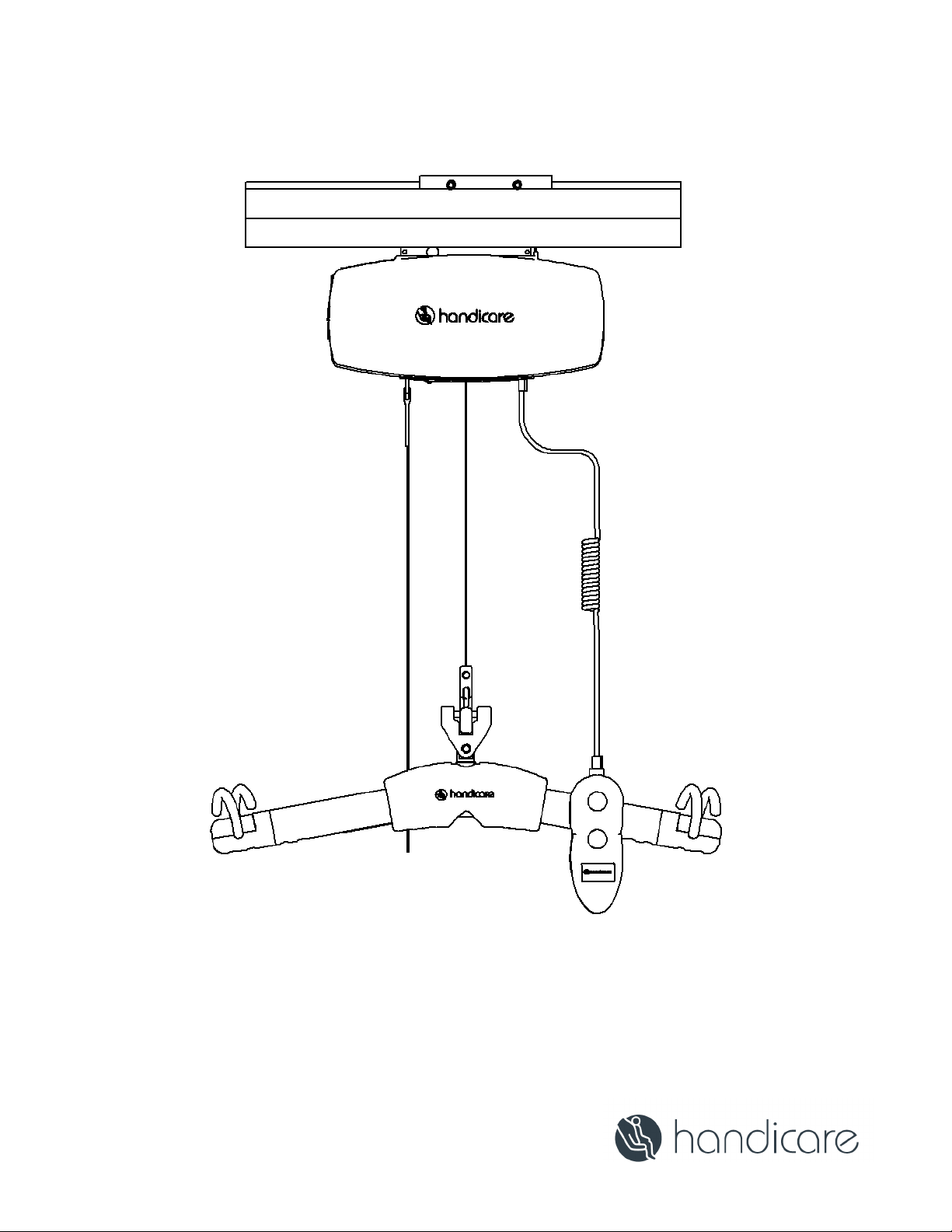
C-450
User manual – English
SWL: 450 lb / 204 kg
Manual: 7531 40 Rev A
Page 2

Cautions
• The C-450/C-625 mu st b e install ed only by persons authorized by Handicare. The installation guide is available to and
for use by a uthorized dealers only.
• Under no circumstance should the C-450/C-625 trac k, l if t, sling, or the entire syst em be put in con t rol of a person who
has not been properly trained i n the use a nd care of this equipm ent. Fai lu re to adhere to this warni ng may re sult in
serious injury to the operator, and/ or the individual being lifted/transferred.
• The C-450/C-625 lift, and associated trac k and s lings are not toys. Do not use it for unsafe practices. Do not allow
children to play with the lift or any of its components.
• The manufacturer's warranty is void if persons unauthorized by Handicare perform work on the C-450/C-625 lift system.
• Only an individual trained by Han dicare shall perform service to the equipment. Refer to technical manuals and training
document s for spe ci fic p rocedures. Improp er or incorrect service may void any warranty.
• In facilities where more than one operator will be responsible for using the C-450/C-625 , associated track , and s li ngs, it
is imperative that all such individuals be trained in its proper u se. A training program s hould be est ablished by the f acility
to acquaint new operators with this equipment. Contac t your l ocal Handicare dea le r or your local Handicare business
development manager for trai nin g assistance.
• Although the hand control is waterproof, the ceili ng lift a nd t he c harger are not. Do not expose the C-450/C-625 lift
directly to water. Warranty does not cover any misuse or abuse of the lift system.
• To maintain optimum function, the C-450/C-625 should be i nspected a nd maintained on a regular basis. Se e t he
section titled “General Inspection and Maintenance.”
• Any accessories use d with the C-450/C-625, inc luding, but not limited to, track and slings, shou ld be check ed to ensure
that they are in good working order. Check for signs of wear or fraying prior to each use. Report any unusual wear or
damage immediately to your local Handicare dealer or your local Handicare business development manager.
• The C-450/C-625 and associated accessories, track, and slings are intended only for lifting, repositioning and
transferring of a person. Handicare will not be responsibl e f or any damage c aused by the misu se, neglect or p urposeful
destruction of the lift, or its associated components. Do not attempt to modify or alter t he C-450/C-625 lifts.
• Do not in any circumstance exceed the maximum allowable load of this lift. Refer to the specifi ca tions section of this
manual, or the labels on the l ift.
• The i ns tallation of the li ft, track, accessories, and sl i ng are certified t o a maximum l oad. Do not exceed t h e max imum
rated load of any of the components.
• There is a risk of explosion if the lift is used in the presence of flammabl e anesthetics.
• Ensure that a clear space is maintained around the lift and track. Move all curtain material and other obstacles out of the
way before performing a transfer.
• The charger must be located outside the patient vicinity at all times. The patient vicinity is the space with surfaces likely
contacted by the patient or an attendant who can touch the patient.
• C-450/C-625 lifts should be decommissioned/disposed of after 10 years of service in accordance with regional
comp onent s pecif ic disposal recommen dations.
2
Page 3

Use and Care
Introduction
To ens ure s afe operation of your C-450/C-625 lift, carefully read this entire manual before usage. The C-450 and C-625 are
designed to be used in conjunction with Handicare/Prism Medical lift track, accessories, and s lings. Refer to the user guides
supplied with these components bef or e usage and refer to them while reviewing this manual.
Be sure to understand the contents of this manual completely before using this equipment.
Failure to comply with warnings in this manual or proper lifting instructions may result in injury to the
operator or the individual being lifted or transferred, as well as damage to the lift and related components.
If you have any questions after reviewing this manual, contact your local Handicare dealer or your local Handicare business
development manager.
Store this manual with the documents included with the lift system, sli ng, and a ll related components. Contents of this manual
are subject to change without prior written notice.
Overview of C-450/C-625 Lift System
The C-450/C-625 is a lifting aid used by health care professionals and caregivers in homes, institutions, and long-term care
facilities to lift, position and transfer clients or a disabled family member.
The C-450/C-625 is one p art of a ceiling lift system that l i fts an individual directly from above, making it possible to transfer
and reposition mobility impaired individuals safely, with dignity, and in comfort while minimizing both strain and risk to the
caregiver. The ceiling lif t also does not take up valuable floor space as most traditional methods do.
The C-450/C-625 lif t is one of the three major parts that make up a ceiling lift system:
Lift - Motorized unit that raises and lowers an individual directly from above
Track - Custom tailored and securely mounted to a ceiling structure, wall or floor provi des the p at h for the lift to tra verse
Sling - Specially designed fabric accessory that attaches to the lift’s carry bar to hold and support an individual for positioning
or transfer
Refer to any user guides supplied with the accessories and reference them while reviewing this lift guide.
C-450 and C-625 Ceiling Lifts
The C-450/C-625 is designed to raise and transfer an individual along a track from one surface to another surface. The lift
remains on the lift track when in use or charging. With manual configurations, the caregiver c an mov e the patient along the
track with minimal push/pull force. Power traverse configurations inclu de a secondary motor that moves the patient along the
track system with no push/pull force. Lifting, lowering, and traverse functions are controlled by the hand controller attached
to the lift.
Lift System
The following parts are included with your new C-450/C-625 lift system:
• Pneumatic hand control
• Charger to be connected to end-point or constant charge contacts
• Owner’s manual
Additional parts may i ncl ude :
• Slings - If a sl ing ha s bee n sup plied w ith t he l if t, ref er to t he inst r u ction s i nclu de d wi th t h e s li ng.
• Accessories - If additional accessories such as a turntable or tra nsi tion gate system have been supplied with the lift, refer
to the instructions included with those items.
3
Page 4
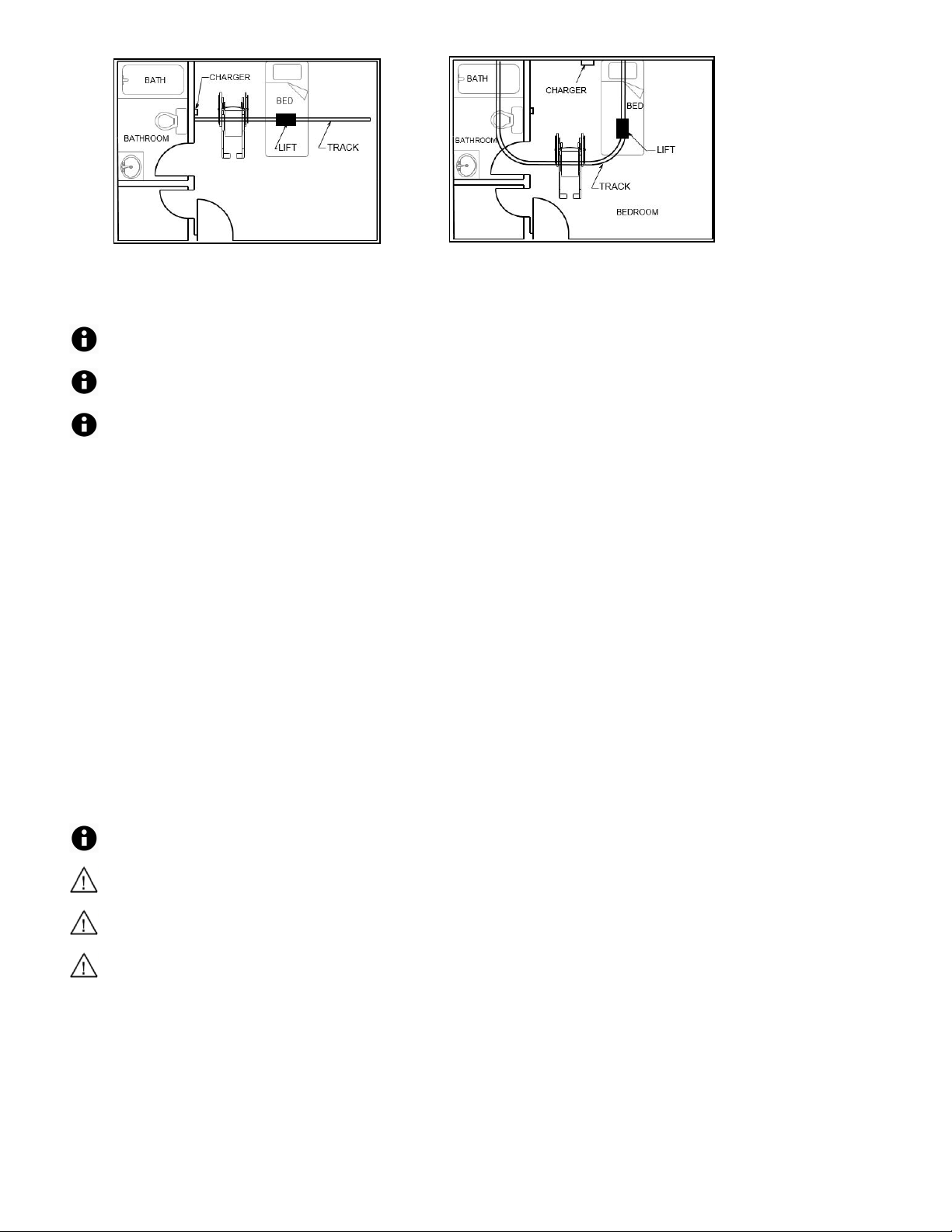
The lift may remain connected to the charger indefinitely since the charger has a built-in regulator to
Figure 1: Installed Lift System Sample Plans
Charging the Lift
Before initial use, the lift unit mu st be charged for 5 hours.
Ch arge the batteries regu l arly. It is recommended th at the lift be left on charge when not in operation to
maximize the life cycle of the batteries.
eliminat e the danger of overcharging.
The ceiling lift charges in one of two options, depending on its configuration:
• End-Point Charging – The rail features a charging point at one end, and the lift must be moved to that point in order
to charge.
• Constant Charging – Charging strips run along the inside of the rail. The lift charges automatically, at any place on
the rail. When the lift is charging, the lift indicator lights solid orange. When charging is complete, the lif t indicator
turns green. Constant charging can be equipped to a ll C-450/C-625 lifts except t hose w it h Return-To-Cha r ge
enabled.
Low Battery
If the batteries of the lift are low and require charging, the indicator located on the underside of the lift lights orange, an audible
alarm sounds every 10 seconds whe n b utt on is p ressed , a nd t he LCD displays Low Batt !. Complete the transfer if one is in
progress and immedi at el y set the l ift to c harge.
The lift may be used after one hour of charging from low battery. It is recommended to charge the lift a minimum of 5 hours to
achiev e maximum battery c apacity.
If th e b atteries a re f u ll y discharged , t he i ndi cat o r on the li ft control p anel lights red an audible alarm will sou nd every 10
seconds when button is pressed, and the LCD displays Low Batt! on first line and UP: INHIBITED! on the second line.
When t he battery is discharged, the up function is disabled. Down, emergency down, and X -Y Traversing
will continue to operate.
Only use the charger that was supplied with the lift. Use of any other charger will void all warranties and
may cause damage to the lift.
Do not position the lift where it is difficult to disconnect the charger in an emergency.
The unit can be isolated electrically from main s by unplugging the charger.
4
Page 5
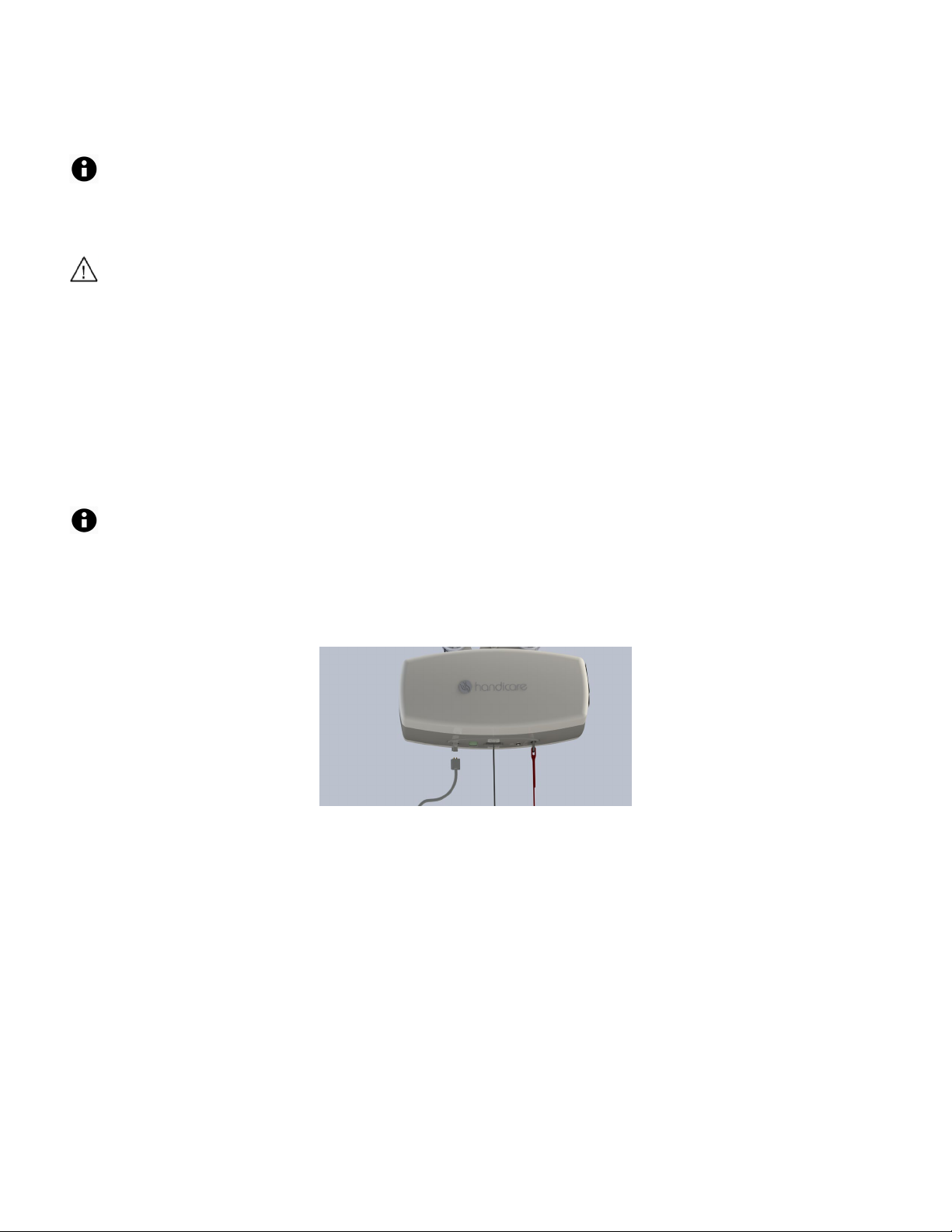
Plug Types
Plug types vary by geographical location. Refer to local el ectri cal gui delines on the typ e of plug or voltage w hich can b e used .
Connection to the charger is an IEC 60320-C7 plug.
C-Series lifts are not compatible with any tracks with track lip separation less than 13.5mm.
Attach the Hand Controller to the Lift
A sturdy ladder may be required to access the underside of the lift to re-attach the hand controller to the lift.
Use caution whenever using a ladder.
Should the hand controller disconne ct from the u nd ersid e of the lift , it must be re-conn ec te d for proper operation.
The hand controller of the C-450/C-625 is designed with met al ri bbed pins to withstand normal usage. However, the
connector can become disc onnec ted if:
• The lift is p ul le d a long the trac k by the hand controller cord
• The hand controller cord gets wrapped around an object while a lift or transfer is being performed
• Hand controller cord is accide ntal ly p u ll ed d own by the caregiver or the individual being lifted
Connect the Hand Control
Make sure that the male connector is inserted into the lift connector in the proper orientation.
1. Line up the small metal ri bbed pins and the grey rubber groomet located on the underside of the lift as shown in
Figure 2.
The hand controller and groomet have a grey rib to be ali gned to insure proper oreintation.
2. Insert the cord connector completel y into the c onnector on underside of the lift sufficiently s o that it is s ec ure.
3. Pull lightly downwards on the connector to confirm proper connection.
Figure 2: Hand controller connector being inserted in to grommet on the lift
Test the Hand Control
Perform a brief test to ensure proper connectivity:
1. Turn on the lift as shown in the section titled “Turn On the Lift”
2. Press any button on the hand controller. The LCD screen light s up on the li ft.
3. Raise and lower the carry bar using the Up button and Down button .
• If the carry bar moves up and down, the hand controller is properl y connec te d, otherwi se check:
• That the lift is on
• That the hand controller connector is properly connected
• That the LCD does not display Down Lim_Sw!
Change the Hand Controller Hook
If an older style C450/C625 carry bar (360760) is to be equipped, it is rec ommened to install a C-Se ries hand controller hook
(635603) on the hand controller for a more secure fit.
5
Page 6
Before using the C-450/C-625 lift system, check t he lift, track, and sling for any unusual wear or
Turn On the Lift
damage. Refer to the owner’s manual for each piece of additional equipment t o determine what should
be checked. If anything looks un usual, contact your local Handicare dealer or your local Handicare
business development manager before use. Failure to check the lift could result in damage to th e lift or
serious injury to the operator or the individual being lift ed.
Press any button on the hand controller to turn the lift on. The indicator on the underside of the lift lights green and the LCD
display screen on lif t wil l turn on.
• If the batteries require charging, the lift indicator lights orange, an audible alarm will sound every 10 seconds whe n the
button is pressed, and the LCD displays Low Batt!.
• If the batteries are discharged below 25% of capacity, the LCD displays Low Batt! and the lift wil l not raise, but will
lower and the emergency lowering will function.
Turn Off the Lift
The lift automatically shuts off after approximately 5 seconds of non-use.
In an emergency, the lift can also be shut off by pulling the emergency down strap. See “Emergency Stop”
section for details on emergency stop and restarting the lift after an emergency stop.
Hand Controller Operation
The C-450/C-625 hand control operates the lift motion.
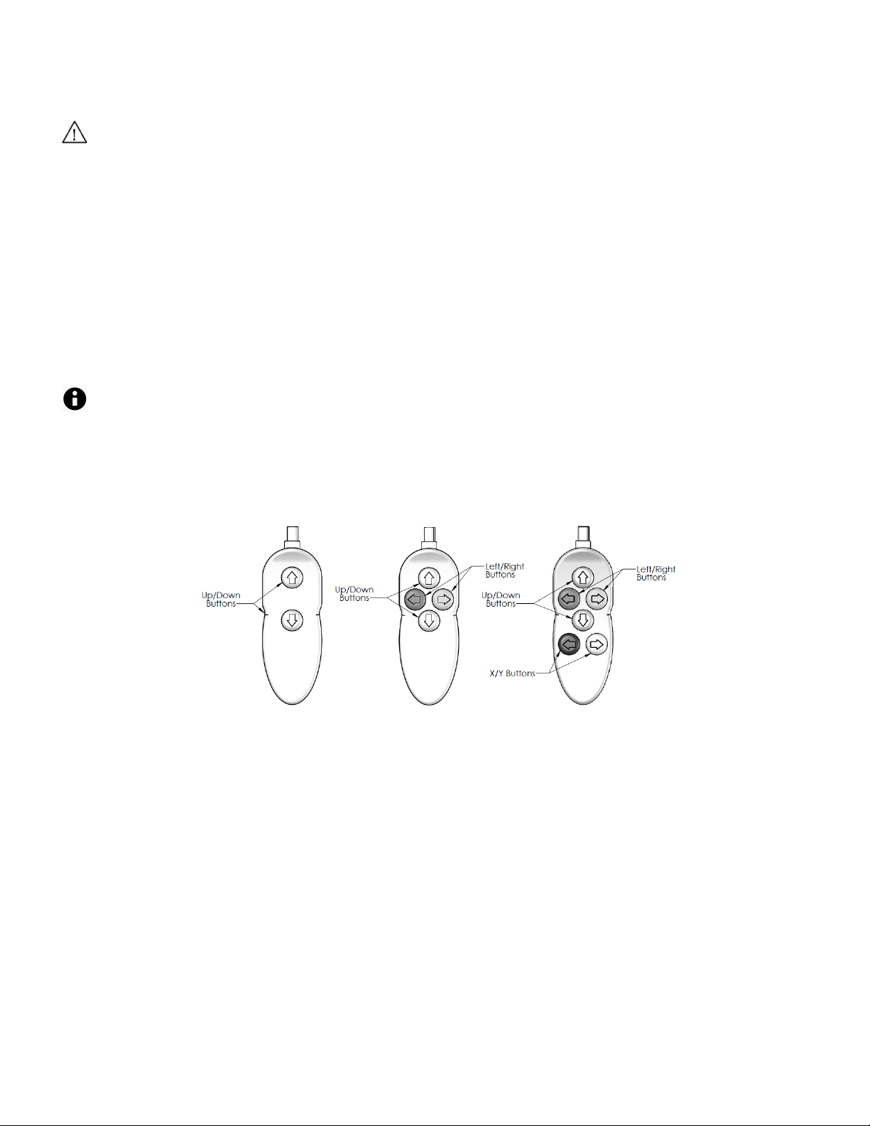
Figure 3 shows the hand controls for Manual Traverse, Power Traverse, and Power Traverse XY lift systems
Figure 3: C-450/C-625 Hand Controls for Manual Traverse, Power Traverse, and
Power Traverse XY Lift Systems
Raise or Lower the Carry Bar
1. Hold the hand controller in one hand.
2. Hold the carry bar in the other hand so that it will not accidentally sway knock into an individual or nearby object.
• To raise the carry bar, press the Up b utton .
• To lower the carry bar, press the Down button .
Move the Lift on the Track
The lift is moved along the track by eit he r manual push/pull force, or by assist of a power traverse motor, depending on unit
configuration.
6
Page 7
The following steps are intended to generally illustrate the procedure of using the lift to transfer an
Ensu re that the carry bar has no cuts, dents, or sharp edges that may come in contact with the straps of the
business development manager.
Transfer an Individual
individual from one location to another.
Configurations vary by installation. Prior to att empting these steps, review the instructions for the sling and
additional accessories you are using with the lift.
1. Complete the “Ea ch Use” inspection found in the “General Inspecti on and Preventive Maintenance” instructions.
2. Mov e the lift cl ose t o the individual to b e t ransf erred .
• Follow the procedures for up and down and moving along the track as described in “Raise or Lower the Carry Bar”
and “Move the Lift on the Track” secti ons.
Avoid any obstructions that may cause injury to the individual in the sling or damage to the lift.
3. Prepare the individual being transferred with the appropriate sling.
• Refer to the instructions supplied with the sling.
Prior t o lifting, make sure that the sling is correctly fitted and adjusted aroun d of the individual for maximum
comfort and safety.
4. Position the l ift direct l y over the individual .
5. Lower the carry bar.
Alw ays check to ensure that the lift is correctly positioned directly above the person to be lifted. The lift
straps may fray over time if repeatedly positioned improperly.
sling and cause damage to them. Report any concerns to your Handicare dealer or your local Handicare
6. Attach the sling loops to the carry bar.
• The s tra ps on each sid e of the sli ng are generally attached to the c orrespondi ng si de of t h e c arry b ar.
7. Double-check to ensure that:
• The straps are properly attached to the carry bar.
• The individual being lifted is properly positioned in the sling prior to lifting.
Prior t o lifting an individual, ensure the hand controller cord is free of the carry bar.
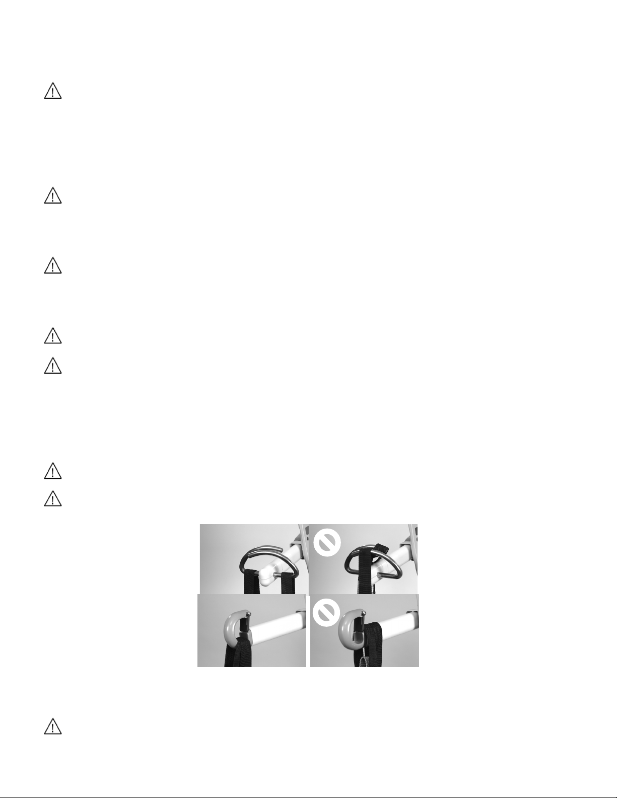
Prior t o lifting an individual, make sure that the straps of the sling are securely placed on the hooks of the
carry bar and that the straps will not come off. (Figure 4).
Figure 4: Sling Straps Properly and Improperly Placed
8. On the hand controller, press the Up but ton . The l i ft raises the indi vidual.
Make sure the individual is lifted to an appropriate height for a safe transfer that avoids any obstr uctio ns
that may cause injury to the individual in the sling or damage to the lift.
7
Page 8

WARNING: STRANGULATION HAZARD
While raising a ceiling lift system with or without patient, ensu re that the patient, caregiver, other
9. Move the individual along the track to the d esi red loca t ion.
• If using a manual traversing lift:
1. Lower the carry bar to a comfortable height so that it can be easily handled.
2. Grab hold of the carry bar and move the lift along the track by gently pushing the carry bar or the individual in the
sling.
• If using a power traversing lift:
1. Use the blue and yellow directional hand cont roller buttons ( and ) to move the lift.
2. The blue and yellow buttons correspond to the blue and yellow directional arrows on the underside of the lift;
simply press the button matching the one on the lift for the direction you want it to move.
Nev er drag the lift along the track by pulling with the h and controller.
10. When the individual is at the de sired l ocati on, press the Down button to lower the individual to the correct height.
Before you remove the sling loops from the carry bar, check that the transferred individual is securely
supported in the appropriate position.
11. Press the Down button to lower the carry b ar so the sling straps can be easily remove d from the carry ba r.
Make sure the carry bar does not contact the individual in the sling.
12. Remove the sling stra ps from the carry bar.
13. Press the Up button to raise the carry bar to a s af e height.
14. Use the blue and yellow directional buttons ( and ) to move the lift out of the way, if equipped (i.e., away f rom
the immediate area).
15. Remove the sling from the individual.
• Store the sling in a safe place.
16. Press the Up button to raise t he c arry b ar t o height whe re i t i s out of the way while not in use.
17. Charge the lift as described in “Cha rging the Lif t.”
Following the completion of the transfer, ensure that the carry bar, strap, and hand control are raised up
away from reach of children, toddlers, or anyone no t intended t o use the product .
Psychological, mental, and emotional state assessment is key to safe use of a ceiling lift; ensure that use
and storage of the ceiling lift and accessories are safe for the patient’s mental condition.
individuals, furniture, and other items are not at risk of becoming ent angled wit h the moving lift strap and
carry bar.
8
Page 9
Traversing Beam Transfer
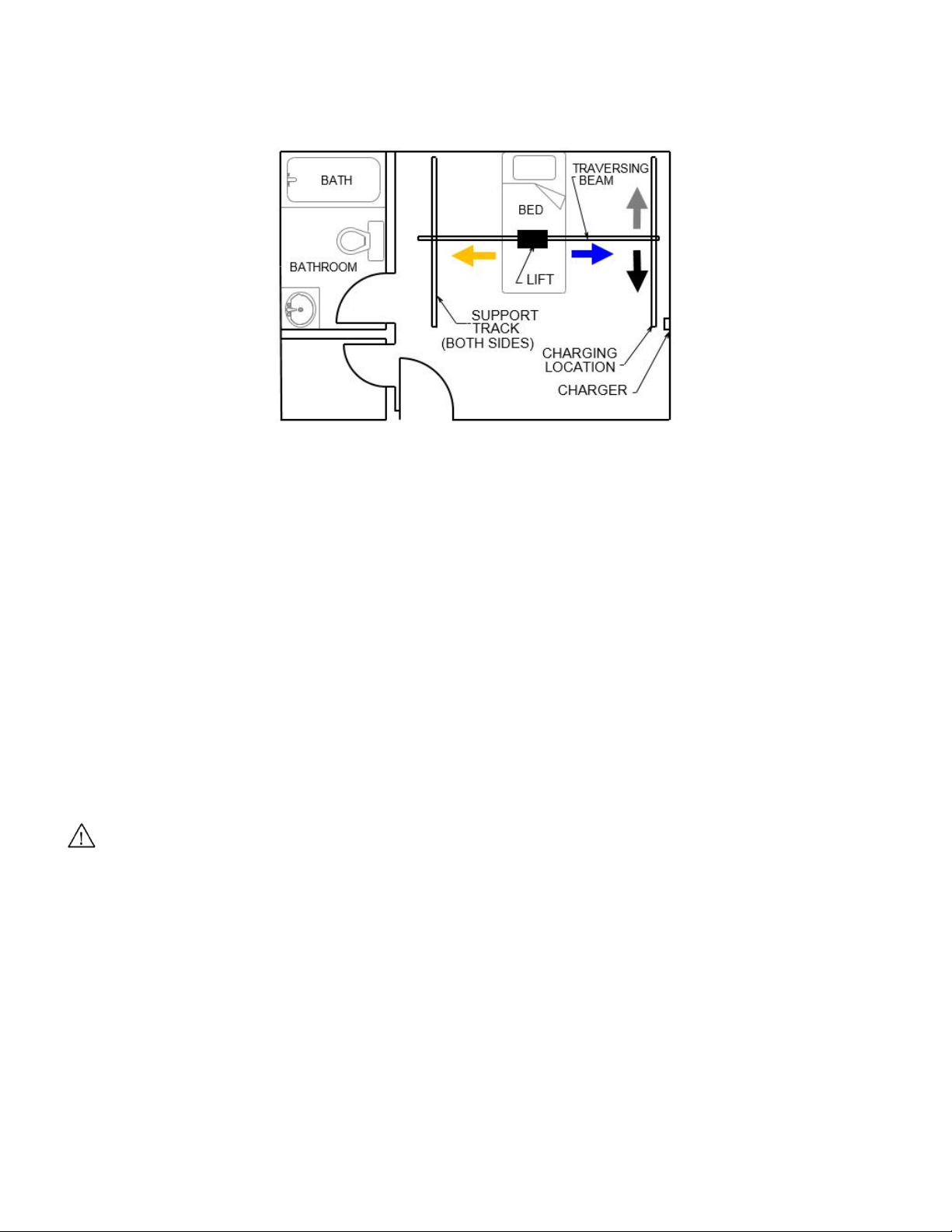
If the ceiling lift is being used in an X-Y system with a traversing b eam, be sure to understand the tra versi ng beam and how it
works in transferring an individual. As shown in Figure 5, the X -Y system features two parall el sup port tracks w ith one
traversing beam mounted across.
Figure 5: X-Y System Featuring Traversing Beam
The lif t c a n be moved al ong t he traversing beam, and the traversing beam itself can be moved along the two parallel support
tracks. Because of this, an X-Y system provides com plete coverage over the area is between the support tracks.
If using a manual traversing beam:
1. Move the beam along the support tracks manually to transport the beam, lift, and indivi dual together.
2. Lower the carry bar to a comfortable height so that it can be easily handled.
3. Grab hold of the carry bar and move the li ft and tra versi ng beam a long t he track by gently pushing the carry bar or the
individual in the sling.
If using a power traversing beam:
1. Move the beam along the support tracks by pressing either the black button or whi te button on the hand controller to
transport the beam, lift, and individual together.
2. Use the black and whi te directional hand controller buttons ( and ) to move the traversing beam.
a. The black and white buttons correspond to the black and whi te direc ti onal arrows on the undersi de of the
power traverse X-Y system lift; simply press the button matching the one on the lift for the direction you want
it to move.
3. Use the blue and yellow directional hand controller buttons ( and ) to move the lift along the traversing beam.
a. The blue and yellow buttons correspond to the blue and yellow directional arrows on the underside of the
traversing lift; simply press the button matching the one on the lift for the direction you want it to move.
When moving the traversing beam, avoid an y obstructions that may cau se injury to the individual in the sling
or damage to the lift or track.
9
Page 10
%B a t e r y 0
5
t
L
i
f
s
,t
x
x x
x
x
LCD Information and Diagnostics
Display Modes
The lift unit can be set to the following display modes:
1. Battery Level (de f aul t)
2. Number of Lifts
To change from one operating mode to another please call your local service technician.
Battery Level
• Displays “Battery” with the percentage charged (in 5% increments) in the top row of the display (e.g., “Battery
65%”).
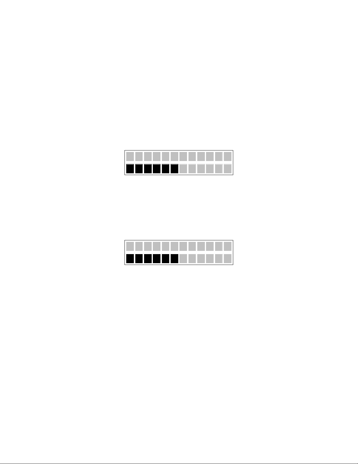
• Displays a bar graph of the battery level in the second row of the display by displaying the appropriate number
of fully blackened rectangles as in the following diagram:
Note: As the lift is initially switched on, the level of battery charge displayed may be incorrect. However, as soon as the
lift is operated, the charge level will update to the correct level.
Number of Lifts
• Displays “Lifts” with the number of lifts completed in the top row of the display (e.g., “Li fts 500”) and a bar graph
to indicate the battery level:
Low Battery Mode
In either display mode, when the battery level fa ll s below 25%, the lift will go into Low Battery Mode. The lift will:
1. Change the indicator light on the lift to ORANGE.
2. Make an audible beep every ten (10) seconds.
3. Display will show the battery % in the first line and the charge level bars in the second line.
If the batteries are fully depleted, the lift will:
1. Change the indicator light on the lift to RED.
2. Make an audible beep every ten (10) seconds.
3. Display will show “Low Batt!”
Charging Display Mode
If the unit is charging, the lift will go into Charging Display Mode, regardless of the default display mode. Charging
Display Mode will override Low Battery Mode.
The lift will display “Charger” with the percentage charged (in 5% increments) in the top row of the display (e.g.,
“Charger 65%”).
10
Page 11

M a
i
t e
n
n a
n c
e
Preventative Maintenance
The lift will recommend preventative maintenance if it hasn’t had se rvice for 1000 lifts or 5 total working hours of
operation, whichever occurs first.
When the lift alerts you that PM is recommended, the lift will:
• Beep every 5 seconds
• The display will alternate between “Maintenance” and the default display mode
If battery is below 25%:
• The indicator light goes to ORANGE
• Beep every 5 seconds
• The display alternates between “Maintenance”
If battery is depleted:
1. The display will FLASH “Low Battery” on the first line
2. The indicator light will go to RED and the beeping will stop
When the lift alerts you that PM is recommended, complete the “Semi-Annually” PM procedure and reset the lift counter.
and the default display mode
Preventative Maintenance Counter Reset
1. The lift must be in power off state.
2. Pres s and hold both Up and Down buttons on hand control. The display will indicate “Tech-Prog” and unit will beep.
3. Release both buttons and press the UP button until “Done” appears in the LED display with a beep.
4. PM Lifts counter will be “zero” (0).
5. Use lift as normal.
11
Page 12
Use of the powered emergency lowering after the patient has been lowered to a safe surface may damage
Following an event where emergency lowering is required, the lift must be inspected and repaired by a
Manual emergency lowering is to only be used if the lowering procedures described pr eviously do n ot
Emergency Stop and Lowering
Emergency Stop
The lift unit has an emergency shut-off f eature, such that in an emergency, power to the li ft can be completely shut off.
To perform an emergency stop, pull down once on the red emergency low eri ng c or d on the und erside of t he l if t unit so that
the emergency switch clicks into the OFF position. In this state, the li ft w ill immedi atel y stop, b eep onc e, the indicator and
display will shut off, and all uni t output will be disabled.
If the emergency stop is activated for any reason, it is re commend ed to perform a complete inspection prior to returning to
service. To restore function to the lift, press the white tab at the top of the red emergency lowering cord back into place.
Powered Emergency Lowering
In the event that the down function on the hand control does not function and the patient can not be lowered by normal means, check that the hand control connection is secure and that the emergency stop has not been activated.
If the down function continues to not operate, the ceiling lift can be lowered by powered emergency lowering, overriding
control functions. To activate, pull and hold down the red emergency lowering cord to the fully extended position.
The lift strap will lower and a continuous alarm will sound as long as the cord is being pulled. Emergency lowering will
stop, and the switch will return to the emergency stop position when the cord is released. Only lower the strap by
emergency lowering to a point where the patient can be safely transferred from the ceiling lift.
the equipment. Misuse of emergency lowering is not covered u nder warranty.
qualified technician.
Manual Emergency Lowering
In the event that both the hand control and powered emergency lowering does not function, the patient can be lowered by manually turning the motor.
function.
A proper safety ladder or stool may be required in order to remove the cover of the device.
DO NOT attempt to use the lift’s functions while using manual lowering.
To perform Emergency Manual Lowering:
1. Locate a 4 m m hex key
• One is supplied with each unit, packaged with the owner’s m anual
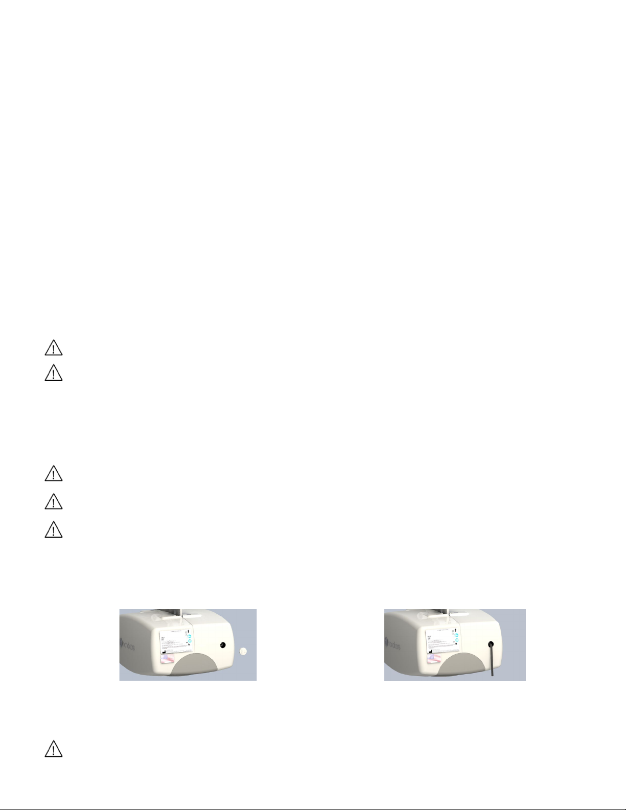
2. Locate and remove the sma ll rou nd clip on the side of the lift (figure 6).
Figure 6: Round plug removed from side cover
Figure 7: Hex key inserted into motor
3. Insert the hex key into the end of the motor driveshaft, exposed through the window (figure 7).
4. Turn the hex key c lockwise t o low er the lift stra p.
Following an event where emergency lowering is required, the lift must be inspected and repaired by a
qualified technician.
12
Page 13
Ensure that no liquids get inside the lift unit. Failure to protect the lift from liquids may result in damage to
Cleaning and Disinfection
Cleaning the Lift and Carry Bar
The exterior of the lift should only be cle aned and disinfected with isopropyl alcohol. Dampen a cloth with isopropyl alcohol
and wipe down the entire exterior of the lif t an d carry bar.
the lift and result in personal injury.
Cleaning the Lift Strap
The lift strap has been tested to be compatible with Virox Accel TB RTU (R ead y-to-Use). Consult your local Handicare
representative for guidance on other disinfectancts.
Do NOT use products containing chlorine, as this will degrade the strap material.
Optional Features
Quick Release Hook
Attach the QRS Carry Bar to the Quick Release Hook
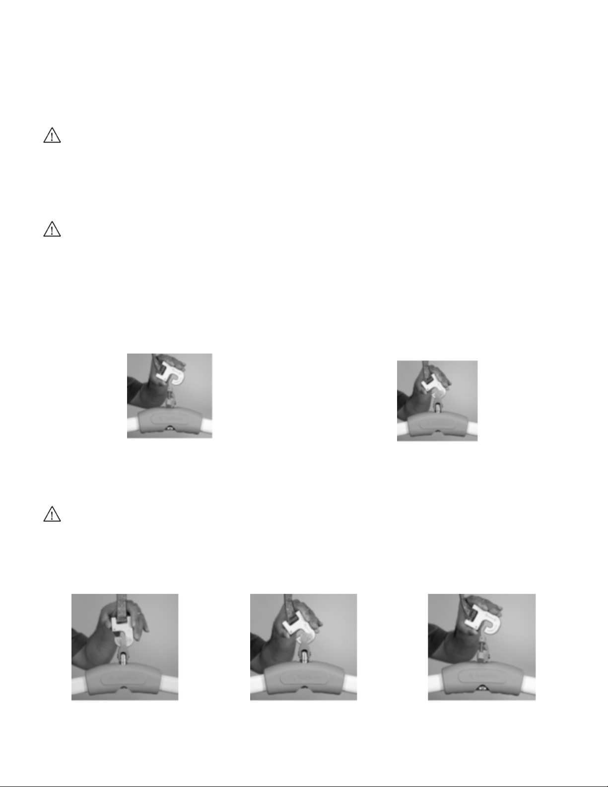
1. Hold down the red latch and ali gn t h e Quick Release Hook sl ot w ith the carry bar’s clevis pin (f igure 8 ) .
Figure 8: Clevis pin of Carry Bar through the red lat ch of
th e QRS H ook
2. Hook the Quick Release Hook onto the carry bar’s clevis pin (fi gure 9).
3. Ma k e s ure the latch is closed completel y once the clevis pin is seated in the Qu i ck Relea se Hook.
If t he lat ch does not close completely, DO NOT USE THE QUICK RELEASE HOOK. Contact your local
Han dicare dealer or your local Handicare business development manager for service.
Figure 9: Carry Bar attached to Quick Release Hook
Detach the QRS Carry Bar from the Quick Release Hook
1. Hold the hook and carry bar.
2. Push the latch down to open it (figure 10).
Figure 10: Open the latch
3. Hold the latch down and tilt the hook about 90° (fi gur e 11).
4. Remov e the carry bar from the q uick rel ease hook (figure 12).
Figure 11: Tilt the hook
13
Figure 12: Remove the Hook
Page 14
The ret urn -to-charge feature can be interrupted manually either by pressing any button on the hand controller
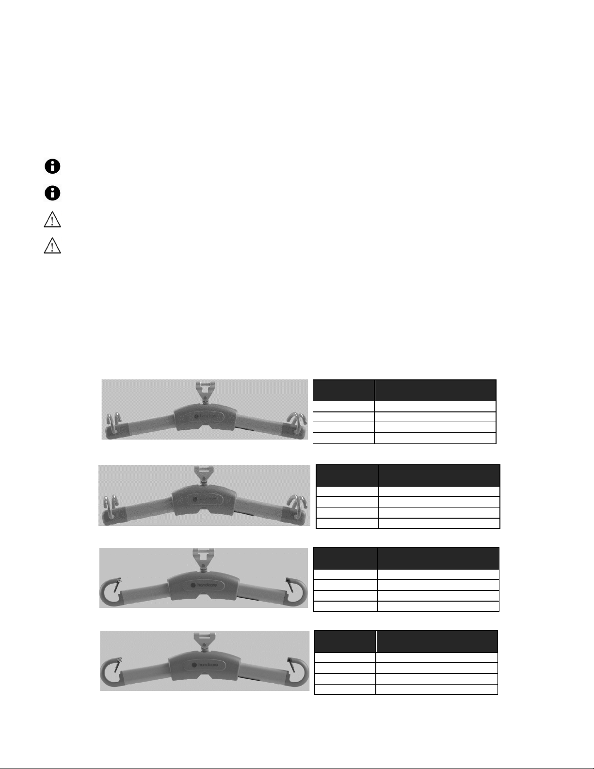
Length between sling
attachments
360933
325mm/12.8in
360932
425mm/16.7in
360931
525mm/20.7in
360930
670mm/26.4in
Length between sling
360937
325mm/12.8in
360936
425mm/16.7in
360935
525mm/20.7in
360934
670mm/26.4in
Length between sling
360983
355mm/14.0in
360982
461mm/18.2in
360981
550mm/21.6in
360980
690mm/27.2in
Length between sling
360987
355mm/14.0in
360986
461mm/18.2in
360985
550mm/21.6in
360984
690mm/27.2in
Return to Charge
If your power traversing lift has return-to-charge (R T C) equipped, press and hold the b lue and ye ll ow colored directi onal hand
controller buttons simultaneously for 3-5 sec ond s until it beeps to activate. The lift automatically ret rac t s the carry bar and
drives along the track unti l i t dock s at t he charger.
If the operator inadvertently enables return-to-charge while a patient is in the lift, the function stops automatically by sensing
excess load on the lift. If the lift’s carry bar get s tangl ed with obst ac les such as furniture or drapery duri ng return-to-charge,
the lift automatically detects the change i n t h e l oad. If the load varies more than 15-30 lb (6.8-13.6 kg), the lif t stop s
automatically. The overload threshold is b etween 35-50 lb (15.8-22.6 kg).
or by grasp ing the carry bar firmly.
The ret urn -to-charge feature does not work with power traversing lifts equipped wit h constant charge (Omni).
Make sure the carry bar is attached to the lift before activating ret urn-to-charge. The added weight of the
carry bar is required to ensure correct limit switch operation.
Avoid any obstructions that may cause injury to the individual in the sling or damage to the lift or track.
Return to Charge features several settings that can be customized:
• RTC Max. Time - The maxi mum time al low ed for t he l if t to trave l to and doc k at the c harger b efore a borting; may be
set in 60 second increments from 60 to 240 seconds
• RT C Drop Time - The time the lift lowers the carry ba r upon docking at the c harger; may b e set in 3 sec increments
from 3 to 24 seconds
• RTC Speed - The relative speed the lift travels at t o reach the c h arger; may be set to 2, 4, 6 or 8
Carry Bars
QRS strap connection – bull horn slin g lo op connection, SWL: 625 lb / 284 kg
Part
Direct strap connection – bull horn sling loop connection, SWL: 625 lb / 284 kg
Part
attachments
QRS strap connection – spring latch sling loop connection, SWL: 625 lb / 284 kg
Part
attachments
Direct strap connection – spring latch sling loop connection, SWL: 625 lb / 284 kg
Part
attachments
14
Page 15
The airline tubing that
connects the hand control to
disengaged.
Refer to “Attach the Hand Controller to the Lift.”
The hand control buttons do
traverse
Ensure that airline tubi ng is properly connected (see “Attach the Hand Controller to the Lift.”)
immediate ly to c heck
The lift strap does not lift up
The indicator light on the control panel located on the underside of the lift should be gre en.
checked to ensure proper continued operation.
The green light on the
DOWN direction.
There is a built-in slack tape detector in the lift. This may be sensitive. Apply weight to the
The red indicator light on the
when an individual is raised.
The batteries are low and require charging. Refer to “Ch a rging the Li ft”. Charge the lift for at
If th i s d oes not correct the problem, contact your loc al authorized de al er i mm ediately to c heck
the lift and ensure proper continued operation.
One side of the lift strap is
Di s c ontinue using immediately and repl ac e stra p. Check to be sure that the lift is always
authorized dealer immediately to check the lift and ensure proper continued operation.
The lift does not pass
Refer to the owner’s manual for the specific piece of equipment in question. If the
No Power
Ensure the Emergency Lowering tab has not come out. If it has, simply press the tab back into
Lift s tarts beeping while
coming down.
The C-Series lift is equipped with dual sensors for strap tension and position. The Emergenc y
Contraindications
There are no known contraindications associated with the use of C-450/C-625 lifts and th ei r accessories,
provided they are used according to manufacturer’s recommendations and guidelines.
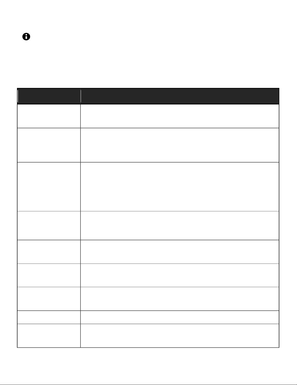
Troubleshooting
Use the fault colum n to loca te the symptom, then compl ete t h e recommended sol uti on in the adjacent column on the row.
If y ou cannot find the fault or the recommended solution does not correct the problem, contact your local Handicare
authorized dealer for service.
Fault Recommended Solution
If th i s d oes not correct the problem, contact your local authorized de aler i mmediately to check
the lift has become
the lift and ensure p roper conti nued operati on.
not operate according to
their designations (e.g. the
UP button initiates a
movement).
or down even when the
airline is properly connected
and hand LCD i s on.
und e rs ide of the lift is On
and LCD is On but the lift
does not operate in the
underside lift turns red or a
loud alarm sound is heard
starting to fray after
continued use.
Ensure the white pl astic tab loc at ed at the end of the red emergency lowering cord is fully
pressed into the lift unit.
Ensure the lift is charged; refer “Cha rging the Lift.”
If th i s d oes not correct the problem, contact your loc al authorized de al er
the lift and ensure proper continued operation.
Press the On button or Up/Down arrow buttons or any colored button on the hand controller.
This should activate the lift and the indicator light turn gree n .
If the lift still does not function, the batteries may be low and require charging. Refer to
“Charging the Lift” and charge the lift f or at least one hour, then try to raise or lower the carry
bar.
If the emergency lowering has been used, the Up and Down functions will not operate. DO
NOT use the lift. Contact your local authorized dealer immediately so that the lift can be
carry bar while pressing the Down button. If this corrects the problem temporarily but not
permanently, cont ac t your local authorized dealer immedi at el y to chec k the lift and ensure
proper continued operation.
leas t one hour and then try to raise or lower the carry bar.
directl y ab ove t h e i ndivi dual bei ng lifted , especia ll y wi th pow er trave rsing li fts. Refer to
Transfer an Individual” for correct lift positioning. If fraying still continues, contact your local
“
through a track component
such as a turntable or
transistion gate.
pulling Emergency Down
Strap/Switch with strap not
recommended solution does not correct the problem, contact your loc al authorized dealer
immediately to check the lift and ensure proper continued operation.
the lift and check b attery f or charge.
Down Strap/Switch system only works with load on the strap and Emergen cy Down
Strap/Switch motion stop immediately after the lift strap is loose.
15
Page 16

Hand Control Button
Press the “UP” on the hand control, strap should start moving out of the lift, continue pressing
the correct orientation.
The lift is recommending
Complete the “Semi-Annually” maintenance procedure prior to resetting the lift counter.
Fault Recommended Solution
Functionality Reversed/Lift
strap sp ooled in reverse
direction/Pulling Emergency
Down Strap/Switch moves
lift strap “UP”
prev e nti ve maintenance.
“UP” button until the strap fully unwinds and will start winding in the correct orientation. Now
the “UP” button will move the strap in the up direction.
If the lift is equipped with RTC feature, activate the RTC function by pressing and holding
“Left and Right” buttons together. The strap will move in the downwards direction unit it
reaches the lowest limit. Once it reaches its lowest limit, the strap w ill start moving up a gain in
16
Page 17

Should any of these items fail the inspection do no t use the lift. Contact your local authorized dealer for
If t he audible/visual preventive maintenance alert sounds, complete the Preventive Maintenance Form
General Inspection and Preventive Maintenance
Do not perform any inspection or maintenance while the lift is in use with a patient.
service.
before resetting the lift counter.
Each Use
To be completed by User
Prior to each use the C-450/C-625 lift and associated t rack, accessori es, and slings must be visually inspected. Refer to the
accessory and sling user guides for specific details regarding their inspection.
Visually check for the following:
The lift strap shows NO signs of fraying or breaking along its entire length.
The s titching on the l ift st rap w here i t connects to the carry bar shows no signs of fraying or breaking.
The slings that will be used shows no signs of unusual wear and tear. The st rap s of the sli ng that connect to the ca rry
bar of the lift show no signs of fraying or breaking. Refer to specific sling instructi on s.
The hand controller cable is not kinked, twisted, knotted, disconnected, or damaged.
All the functions on the hand controller work correctly (e.g. Up/D own/Left/Right, e tc .).
There are no cuts, dents or sharp edges on the carry bar that may damage the s ling straps.
The lift has no unusual sounds when the carry bar is moved up or down or the lif t is moved left or right.
Ensure that end stops are installed at each end of the track.
Monthly
To be completed by User
Compl e te t he v isual insp ect i on as noted in the “Each Use” sec ti on above .
With no one in the sling nor attached to the lift, chec k that t he l ift moves f ree ly al ong the entire lengt h of the track.
Semi-Annually
To be completed by User
In high frequency transfer areas (more than 1500 lifts per year) or situations where heavier than normal clie nts are regularly
lifted, maint e nanc e should also be completed every 6 months. It is recommended that this service history be documented.
Check emergency stopping and emergency lowering functions using the red emergency cord.
Inspect carry bar for damage; verify insert and hooks. Ensure there are NO cuts, dents, or sharp edges that may
damage the strap of the unit or sling.
Lower the lift strap all the way out of the unit; verify there are no signs of fraying or breaking along its entire l ength.
(C-Series Carry Bars only) Remove the plug from the carry bar and inspect the integrity of the strap around t he pin.
The stitching on the lift strap where it connects t o the carry bar shows NO signs of fraying or breaking.
Verify all functions on the hand controller work correctly (Up, Down, Traversing, Return to Charge, etc.).
The lift makes no unusual sounds when the carry bar is moved up or down or the lift is moved left or right.
Press and hold the Up button until the carry bar is at the top. The motor should stop automatically.
Using the hand controller, let the strap out all the way to the ground. The motor should stop before the strap begins to
wind backwards.
Check that the unit is charges properly. The ind ic ator on the lift should light orange.
Check that the lift’s LED light indicates green when on, dark when off, and orange when charging
Check for cracks or wear in the case.
Annually
This section to be only completed by a qualified service technician as authorized by Handicare.
Complete the inspection as noted in the “Monthly” section above.
Compl e t e t he p reventive m ai nte na nce p rocedure as outlined i n t he C-Series Service/Sp are Parts Manual.
17
Page 18

Lift Motor:
24 VDC
Trav erse Motor:
24 VDC (O ptional at time of Purchase )
XY Traverse Motor:
24 V D C (Op t ional at ti me of Purchase)
Charger:
Model: Soneil, 2403SRM20
Input: 100-240 VAC 1.5 Amps, 50-60 Hz
Output: 24 VDC, 1.0 Amps
Note: Only use the Soneil, 2403SRM30 or Mascot 9940 chargers as alternates with the C-450/C625 Lift. Other chargers, including the A450/A625 charger, are not compatible to the C-450/C-625.
Batteries:
24 VDC (2 x 12 VDC) 5.0 AH, Sealed Lead Acid
Li ft Cas e:
Flame Retardant ABS
Hand control:
Pneumatic
Main Unit IP Rating
IP22
water drops up to 15 degrees
Lifting Range:
Up to 96” (2438mm)
Lift Weight:
21—23.5 lb (9.5-10.65 kg)
Maximum Safe
450 lb / 204.5 kg (C-450) or 625 lb / 284 kg (C-625).
prod uct label l ocated on the bottom of the lift.
Du t y Cycl e:
1 Min On—9 Mins Off
Max Sound Level:
Raising Max load 56.1 dB, Lowering Max load 60.3 dB on a lift in good working order.
Service Life:
22,500 cycles or 10 years, whi chever com es earlier.
lifting strap. See “G eneral Inspection and Preventive Maintenance.”
Usage Environmental
Temperature: +5º to + 40º C (41 to 104 °F)
Relative Humidity: 15 to 90% R H
Atmospheric Pressure: 70 to 106 hPa
Storage
Temperature: -40º to + 70º C (-40 to 158 °F)
Relative Humidity: 10 to 100% RH
Atmospheric Pressure: 500 to 1060 hPa
Rated Performance:
30-40 lifts at 625 lb (284 kg)
C-450/C-625 Lift Specifications
IP22 = Protected against access to ha zardous part by finger, protected against vertically falling
Working Load:
Conditions:
Environmental
Conditions
Note: The max imum saf e w orking load (SWL) of t h e i nstalled l ift is determined by referring to t h e
As a precautionary measure, the lifting strap should be replaced every 5000 cycles or 3 years,
whichever comes earlier. Higher usage lifts may necessitate more frequent replacement of the
50-60 lifts at 450 lb (204.5 kg)
1 min “on”, 9 min “off”
Each lift being 24” (610 mm) at the middle of the lifting range (from 54” (1370 mm) strap out to 30”
(762 mm) strap out) per full battery)
Note: The lift has a break in period; breaking in of the lift will need to be d one be fore these
numb ers wil l be achieved. The b reak ing in p eri od vari es f rom lift to lift a nd d epends on the
frequency of use and the types of load being applied. Higher loads and a greater frequency of use
break in the lift faster.
18
Page 19
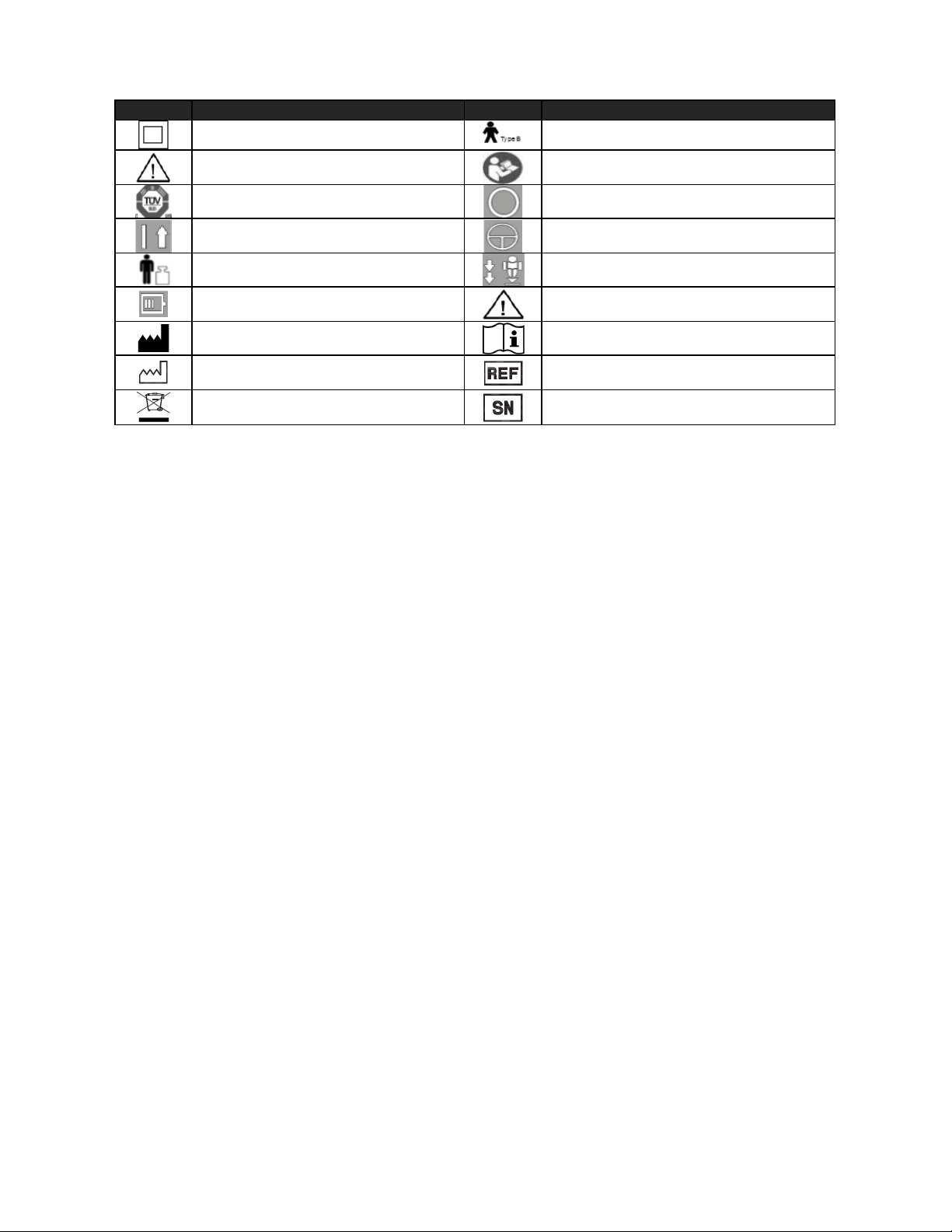
Symbol
Definition
Symbol
Definition
Caution risk of danger or Attention,
consult accompanying Documents
Status LED’s for battery level and
sy s tem error i nd ication
Manufacturer as defined in EU
directive 93/42/EEC
C-450/C-625 Lift Display Symbols
Class II equipment
Typ e b applied part
Refer to instructions manual/booklet
Certified by TUV
On Power
Body Weight
Off Power
On/Off
EMERGENCY DOWN
General Warning Sign
Refer to Instructions, Manual, Booklet
Date of Manufacturing
WEEE wheeled bin
Model/Catalogue Number
Prod uct Se ri al Number
19
Page 20

Warranty
This Warranty does not affect or in any way limit your Statutory Rights.
Ha nd icare guarantees a ll equipme nt, which includes Cei ling Lif ts, Floor Lifts, Slings, Servi ce Parts an d Track and accessories,
supplied as new, against failure within the period of 1 year from date of installation or 18 months from date of manufacturing,
whichever is shorter, by virtue of defe ct s in material or workmansh ip.
Handicare guarantees all ref urbi shed equip ment suppl ied against fa ilure within a period of t h ree mont hs from d ate of
ins ta l lation or si x months f rom date of purchase whi ch ever is s horter.
This guarantee does not apply to failure attributable to normal wear and tear, damage by natural forc es, user neglect or
misuse or to deliberate destruction, or to batteries more than 90 days after original purchase.
This guarantee shall be void if the equipment is not serviced by Handicare or its authorized service agents in accordance with
the manufacturer’s recommendations or if any unauthorized person carries out works on the equipment.
The l i abi li ty of Han dicare under t he te rms of this guarantee shal l be lim it ed to the repl ac ement of de fective parts and i n no
event shall Handicare incur liability for any consequential or unforeseeable losses.
Al w ay s make sure you have the correct ve rsion of the manual . The m ost rec ent version is a vaila ble on our website,
www.handicare.com
For questions about the manufacture or operation of this equi pment, contact your loca l Handi care d ealer or your local
Handicare business development manager.
About Handicare
Ha nd icare of fers s olutions and support to increase the i ndependence of the physica ll y chall enged or elderly people and to
enable them to live an active life—on thei r terms—and to fa ci litate for t heir care provi ders and fa mi ly. The offering
encompasses a comprehensive range of curved and straight stairlifts, transfer, lifting and repositioning aids, vehicle
adaptations and medical equipment. Handicare is a global company with sales in more than 20 countries and is a market
leader in this field. The head office is in Stockholm, Sweden and manufacturing is located at six sites distributed across North
America, Asia and Europe.
 Loading...