

HAMPTON BAY Midili, Midili 903 913, Midili 836 901 Owner's Manual
Midili
44
in Ceiling Fan
Owner’s Manual
Midili
Ventilador de Techo de 1,12
m
Manual del Propietario
903 913
836 901
213 mm
The spot color is for reference proof only, please follow
pantone guide for actual color when printing.
This line is for die-cut position only
DO NOT PRINT IT!!!
Black Magenta Yellow Black PMS 465C PMS 5425C PMS 632C Die
Total Colors
Coating
Varnish
ADDITIONAL INFORMATION
V0.0
17 Apr 09
V0.0
17 Apr 09
V0.0
17 Apr 09
V0.0
17 Apr 09
V0.0
17 Apr 09
V0.0
17 Apr 09
V0.0
17 Apr 09
V0.0
17 Apr 09
V0.0
17 Apr 09
V0.0
17 Apr 09
V0.0
17 Apr 09
V0.0
17 Apr 09
V0.0
17 Apr 09
V0.0
17 Apr 09
1. UPC at 100% and without truncated.
2. The smallest fonts size is 6 points in the artwork.
Size:
C.S.:
Date:
HD_014852A_903913_MC
V0.0
Home Depot
N/A
US
TBA
Hampton Bay (Ceiling Fan)
KOF CLZ
Offest
TBA
213(L) x 150(W) mm
213(L) x 150(W) mm
Mary
Chris Que
10-01-22

44” Midili
Ceiling Fan by Hampton Bay
Steeper Blade Pitch for
Greater Air Movement
3-Speed Reverse Function for
Year-Round Comfort and Savings
Standard Handheld Remote
Control Included
Dual-Mount Installation
QUESTIONS, PROBLEMS, MISSING PARTS:
Before returning to your local Home Depot, please call our
Customer Service Team at 1-877-527-0313 or visit www.homedepot.com.
Please reference your SKU (903 913 brushed nickel, 836 901 gilded espresso)
or UPC (082392 68044 2R brushed nickel, 082392 68100 5 gilded espresso).
Thank you for purchasing this Hampton Bay ceiling
fan. This product has been manufactured with the
highest standards of safety and quality. The nish
of this fan is weather resistant, but over time will
naturally weather and fade.
Safety Rules .................................. 1
Unpacking Your Fan .................... 2
Installing Your Fan ...................... 3
Operating Your Fan ..................... 9
Operating Your Remote ............... 10
Care of Your Fan .......................... 11
Troubleshooting ............................ 11
Specications ................................ 12
Warranty Information .................13
Table of Contents
UL Model Number 44-MDL
1. To reduce the risk of electric shock, insure electricity
has been turned off at the circuit breaker or fuse box
before beginning.
2. All wiring must be in accordance with the National
Electrical Code ANSI/NFPA 70-1999 and local electrical
codes. Electrical installation should be performed by a
qualied licensed electrician.
3. WARNING: To reduce the risk of re or electric shock, this
fan should only be used with fan speed control part no. FAN18R, manufactured by Chia Wei Electric Co., Ltd.
4. CAUTION: To reduce the risk of personal injury, use only
the screws provided with the outlet box.
5. The outlet box and support structure must be securely
mounted and capable of reliably supporting a minimum of
35 pounds. Use only UL Listed outlet boxes marked “FOR
FAN SUPPORT.”
6. The fan must be mounted with a minimum of 7 feet
clearance from the trailing edge of the blades to the oor.
7. Do not operate reversing switch while fan blades are in mo-
tion. Fan must be turned off and blades stopped before reversing blade direction.
8. Avoid placing objects in path of the blades.
9. To avoid personal injury or damage to the fan and
other items, be cautious when working around or
cleaning the fan.
10. Do not use water or detergents when cleaning the fan or fan
blades. A dry dust cloth or lightly dampened cloth will be
suitable for most cleaning.
11. After making electrical connections, spliced conductors
should be turned upward and pushed carefully up into
outlet box. The wires should be spread apart with the
grounded conductor and the equipment-grounding
conductor on one side of the outlet box and ungrounded conductor on the other side of the outlet box.
12. Electrical diagrams are for reference only. Light kits that are
not packed with the fan must be UL Listed and marked suitable for use with the model fan you are installing. Switches
must be UL General Use Switches. Refer to the instructions
packaged with the light kits and switches for proper assembly.
13. All set screws must be checked and retightened where
necessary before installation.
Safety Rules 1.
READ AND SAVE THESE INSTRUCTIONS
TO REDUCE THE RISK OF FIRE, ELECTRIC SHOCK OR PERSONAL INJURY, MOUNT FAN TO OUTLET BOX MARKED ACCEPTABLE FOR FAN
SUPPORT WITH THE SCREWS PROVIDED WITH THE OUTLET BOX.
TO REDUCE THE RISK OF SHOCK. THIS FAN MUST BE INSTALLED
WITH AN ISOLATION WALL CONTROL/SWITCH.
TO REDUCE THE RISK OF PERSONAL INJURY, DO NOT BEND THE
BLADE BRACKETS (ALSO REFERRED TO AS (“FLANGES”) DURING
ASSEMBLY OR AFTER INSTALLATION. DO NOT INSERT OBJECTS IN
THE PATH OF THE BLADES.
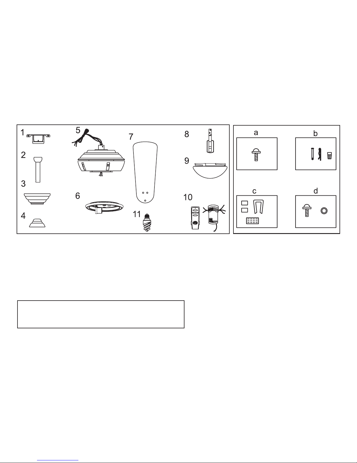
a. Blade attachment hardware
(15 Screws)
b. Mounting & Electrical Hardware
(1 hanger pin, 1 locking pin,
3 plastic wire connectors)
c. Blade Balancing Kit
d. Blade Bracket Hardware
(10 screws and lockwashers)
7. Blades (5)
8. Blade brackets (5)
9. Glass
10. Hand Unit/Receiver
11. Bulb (1)
1. Mounting Plate (inside canopy)
2. Downrod and Ball Assembly
3. Canopy
4. Decorative Motor Collar Cover
5. Fan Motor Assembly
6. Light Kit Assembly
2. Unpacking Your Fan
IMPORTANT: THIS PRODUCT AND/OR COMPONENTS ARE COVERED
BY ONE OR MORE OF THE FOLLOWING U.S. PATENTS: 5,947,436;
5,988,580; 5,971,573; 6,010,306; 6,039,541; 6,046,416 AND OTHER
PATENTS PENDING.
Unpack your fan and check the contents. You should have the following items:
Installing Your Fan 3.
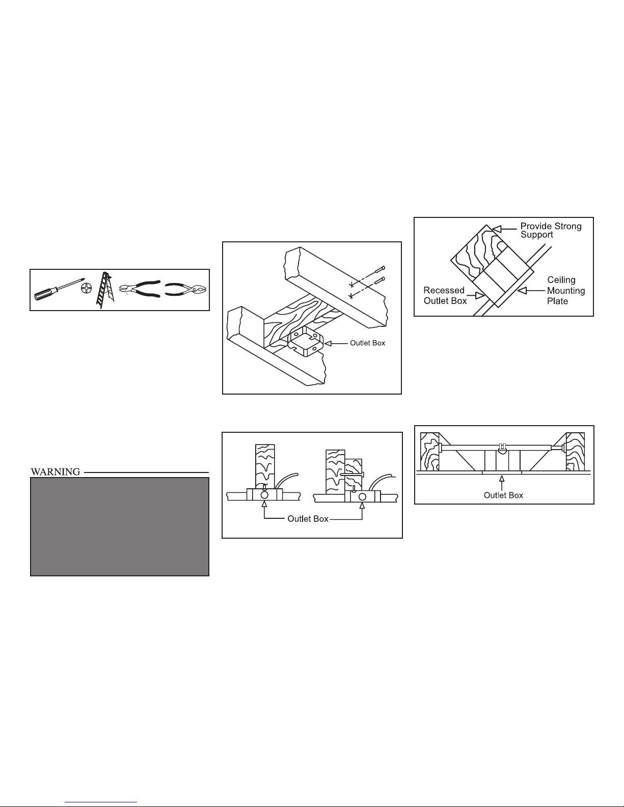
Tools Required
Phillips screw driver, straight slot screw
driver, adjustable wrench, step ladder, and
wire cutters.
Mounting Options
If there isn’t an existing outlet box, then read
the following instructions. Disconnect the
power by removing fuses or turning off
circuit breakers.
Secure the outlet box directly to the building
structure. Use appropriate fasteners and
building materials. The outlet box and its
support must be able to fully support the
moving weight of the fan (at least 35 lbs.)
Do not use plastic outlet boxes.
Figures 1, 2, and 3 are examples of different
ways to mount the OUTLET BOX.
Note: You may need a longer downrod to
maintain proper blade clearance when installing on a steep, sloped ceiling. The maximum
angle allowable is 30˚. If the canopy touches
downrod, remove the decorative canopy
bottom cover and turn the canopy 180˚ before
attaching the canopy to the mounting plate.
To hang your fan where there is an existing
xture but no ceiling joist, you may need an
installation hanger bar as shown in Figure 4
(available at your Hampton Bay retailer).
TO REDUCE THE RISK OF FIRE, ELECTRIC
SHOCK OR PERSONAL INJURY, MOUNT
FAN ONLY TO AN OUTLET BOX MARKED
ACCEPTABLE FOR FAN SUPPORT AND
USE THE MOUNTING SCREWS PROVIDED
WITH THE OUTLET BOX. OUTLET BOXES
COMMONLY USED FOR THE SUPPORT OF
LIGHTING FIXTURES MAY NOT BE ACCEPTABLE FOR FAN SUPPORT AND MAY NEED TO
BE REPLACED. CONSULT A QUALIFIED ELECTRICIAN IF IN DOUBT.
Figure 1
Figure 2
Figure 4
Figure 3
4.
Hanging the Fan
REMEMBER to turn off the pow-
er. Follow the steps below to hang your
fan properly.
NOTE: This fan is recommended for the
standard ceiling mounting using the downrod
provided with this fan. When using standard
ceiling installation with the 4.5 inch downrod
provided, the distance from the ceiling to the
bottom of the fan blades will be approximately
11 inches.
Standard Ceiling Mounting
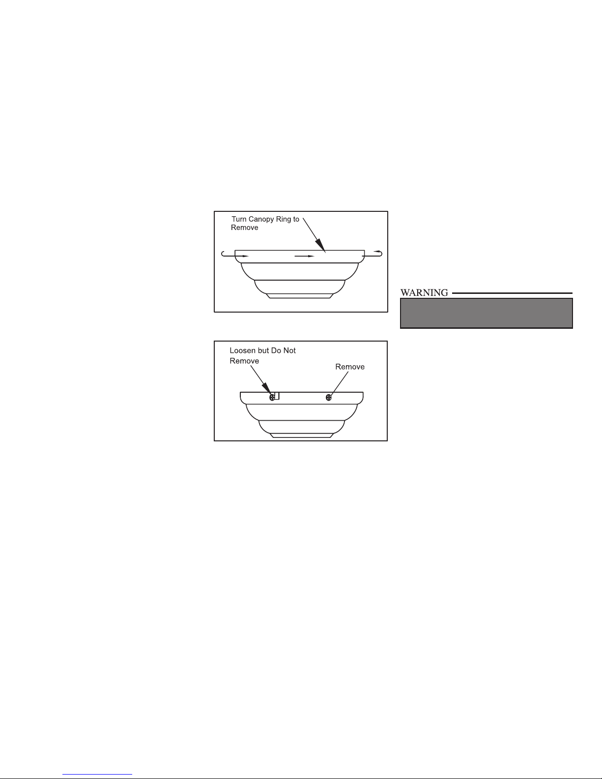
1. Remove the canopy ring from the canopy
by turning the ring to the right until it
unlocks (Figure 5).
2. Remove the mounting plate from the
canopy by loosening the four screws on
the top of the canopy. Remove the two
non-slotted screws and loosen the slotted
screws. This will enable you to remove the
mounting plate (Figure 6).
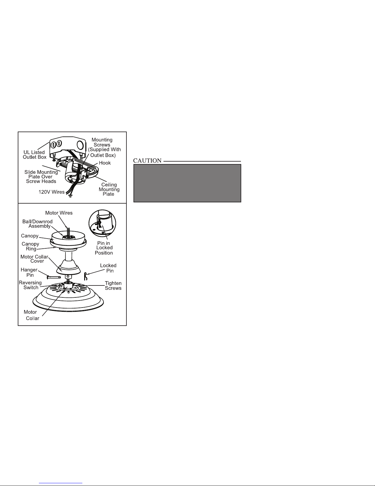
3. Route the wires exiting the top of the
fan motor through the decorative motor
collar cover then the canopy ring. Make sure
the slot openings are on top. Route the wires
through the canopy and then through the
ball/downrod assembly (Figure 7).
Figure 5
Figure 6
4. Loosen, but do not remove, the set
screws on the collar on the top of the
motor housing.
5. Align the holes at the bottom of the
downrod with the holes in the collar
on top of the motor housing (Figure 7).
Carefully insert the hanger pin through
the holes in the collar and downrod. Be
careful not to jam the hanger pin against
the wiring inside the downrod. Insert the
locking pin through the hole near the
end of the hanger pin until it snaps into its
locked position, as noted in the circle inset
of Figure 7.
6. Re-tighten the set screws on the collar on top
of the motor housing.
7. Make sure the grommet is properly installed
in the collar cover, then slide the collar cover
on the downrod until it rests on the motor
housing. Be sure that the canopy and the collar cover are both oriented correctly.
8. Proceed to “Installing the Fan” section.
FAILURE TO PROPERLY INSTALL SET SCREWS
AS NOTED IN STEP 6 COULD RESULT IN FAN
LOOSENING AND POSSIBLY FALLING.
5.
Figure 7
Installing Fan to
the outlet box
WHEN MOUNTING THE FAN ON A SLOPED
CEILING, THE STANDARD BALL/DOWNROD
MOUNTING METHOD MUST BE USED. THE
MOUNTING PLATE MUST BE MOUNTED SO
THAT THE SLOT OPENINGS ARE ON THE
LOWER SIDE BY SLIDING THE MOUNTING
PLATE FROM THE TOP DOWN.
1. Pass the 120-volt supply wires through the
center hole in the ceiling mounting plate as
shown in Figure 7.
2. Install the ceiling mounting plate on the outlet box by sliding the mounting plate over
the two screws provided with the outlet box
(Figure 7). If necessary, use leveling washers (not included) between the mounting
plate and the outlet box. Note that the at
side of the mounting plate is toward the outlet box (Figure 7).
3. Securely tighten the two mounting screws.
4. Carefully lift the fan assembly up to the
ceiling mounting plate. Make sure the tab
on the mounting plate is properly seated in
the groove in the hanger ball.
Making the Electrical
Connections
REMEMBER to disconnect the power. If
you feel you do not have enough electrical
wiring knowledge or experience, have your fan
installed by a licensed electrician.
Follow the steps below to connect the fan
to your household wiring. Use the wire
connecting nuts supplied with your fan
and supplied with remote control. Secure the connectors with electrical tape.
Make sure there are no loose strands or
connections (Figure 8).
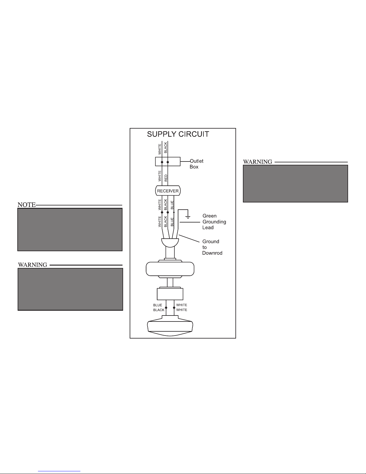
1. Connect the ground conductor of the 120v
supply (this may be a bare wire or a wire
with green colored insulation) to the green
ground lead(s) of the fan (Figure 8).
2. Connect the fan motor white wire to
the receiver white wire using a wire nut
(Figure 8).
3. Connect the fan motor black wire to
the receiver black wire using a wire nut
(Figure 8).
4. Connect the fan motor blue wire to the re-
ceiver blue wire using a wire nut (Figure 8).
5. Connect the receiver red wire to the sup-
ply black (hot) wire using a wire nut
(Figure 8).
6.
6. Connect the receiver white wire to the sup-
ply white wire (neutral) wire using a wire
nut (Figure 8).
7. After connecting the wires, spread them
apart so that the green and white wires are
one side of the outlet box and the black wire
is on the other side.
8. Turn the wire connecting nuts upward and
carefully push the wiring into the outlet
box.
EACH WIRE NUT (WIRE CONNECTOR) SUPPLIED WITH THIS FAN IS DESIGNED TO ACCEPT
UP TO ONE 12 GAUGE HOUSE WIRE AND TWO
WIRES FROM THIS FAN. IF YOU HAVE LARGER
THAN 12 GAUGE HOUSE WIRING OR MORE
THAN ONE HOUSE WIRE TO CONNECT TO THE
FAN WIRING, CONSULT AND ELECTRICIAN FOR
THE PROPER SIZE WIRE NUTS TO USE.
THE FREQUENCIES ON YOUR RECEIVER AND
TRANSMITTER HAVE BEEN PRESET AT THE
FACTORY. BEFORE INSTALLING THE RECEIVER, MAKE SURE THE DIP SWITCHES ON THE
RECEIVER AND TRANSMITTER ARE SET TO
THE SAME FREQUENCY. THE DIP SWITCHES
ON THE TRANSMITTER ARE LOCATED INSIDE
THE BATTERY COMPARTMENT.
Finishing the Fan
Installation
STANDARD CEILING MOUNTING
1. Align the locking slots of the ceiling canopy
with the two screws in the mounting plate.
Push up to engage the slots and turn clockwise to lock in place. Immediately tighten
the two mounting screws rmly.
2. Install the remaining two mounting
screws into the holes in the canopy and
tighten rmly.
3. Install the decorative canopy ring by
aligning the ring’s slots with the screws
in the canopy. Rotate the ring counterclockwise to lock in place.
4. You may now proceed to attaching the
fan blades.
WHEN USING THE STANDARD BALL/DOWNROD
MOUNTING, THE TAB IN THE RING AT THE BOTTOM OF THE MOUNTING PLATE MUST REST IN
THE GROOVE OF THE HANGER BALL. FAILURE
TO PROPERLY SEAT THE TAB IN THE GROOVE
COULD CAUSE DAMAGE TO WIRING.
Figure 8
7.
Attaching the
Fan Blades
NOTE: Your fan blade are reversible. Select the
blade side nish which best accentuates your
decor.
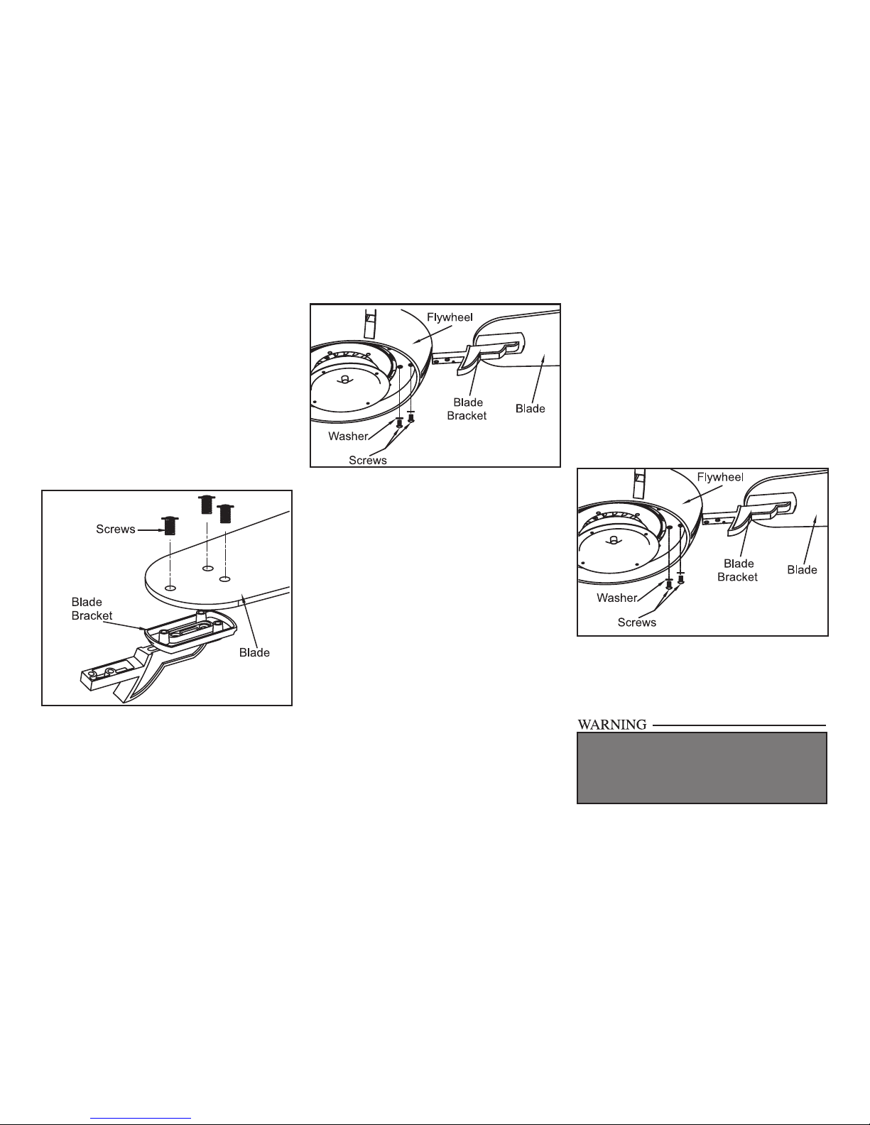
1. Attach blade to blade bracket using the
screws supplied (Figure 9). Start a screw
into the bracket. Repeat for the two remaining screws.
2. Tighten each screw securely.
3. Insert the blade/blade bracket assembly
through the hole in the side of the center
y wheel, align the two screws holes in the
bracket with the screw holes in the center
ywheel and secure with screws and lockwashers supplied (Figure 10).
Figure 10
Figure 11
Blade Balancing
All blades are grouped by weight. Because natural woods vary in density, the fan may wobble
even though the blades are weight matched.
The following procedure should correct most
fan wobble. Check after each step.
1. Check that all blade screws are secure.
2. Most fan wobble problems are caused when
blade levels are unequal. Check this level by
selecting a point on the ceiling above the tip
of one of the blades. Measure from a point
on the center of each blade to the point on
TO REDUCE THE RISK OF PERSONAL INJURY,
DO NOT BEND THE BLADE HOLDERS WHILE
INSTALLING, BALANCING THE BLADES, OR
CLEANING THE FAN. DO NOT INSERT FOREIGN
OBJECTS BETWEEN ROTATING BLADES.
the ceiling. Measure this distance as shown
in Figure 11. Rotate the fan until the next
blade is positioned for measurement. Repeat for each blade. Measurement deviations should be within 1/8”. Run the fan for
10 minutes.
3. Use the enclosed Bladed Balancing Kit if
the blade wobble is still noticeable.
Figure 9
4. Repeat steps 1-3 for the remaining blades.
 Loading...