


PORTABLE AIR CONDITIONER
INSTRUCTION MANUAL
Read Rules for Safe Operation and Instructions Carefully.

! |
CAUTION |
! |
Do not leave this unit unattended in a space where people or animals who cannot react to a failed unit are located. A failed unit can cause extreme overheating or death in such an enclosed, unattended space.
2
Electrical Specifications
1.All wiring must comply with local and national electrical codes and be installed by a qualified electrician. If you have any questions regarding the following instructions, contact a qualified electrician.
2.Check available power supply and resolve any wiring problems BEFORE installation and operation of this unit.
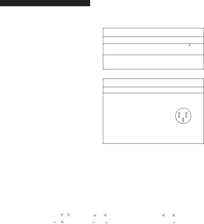
3.This unit draws 7.4 amps (nameplate rated) under Cooling mode and 12.0 amps (nameplate rated) under Heating Mode and may be used in any properly wired, general purpose 15 amp household grounded receptacle.
4.For your safety and protection, this unit is grounded through the power cord plug when plugged into a matching wall outlet. If you are not sure whether the wall outlets in your home are properly grounded, please consult a qualified electrician. DO NOT USE PLUG ADAPTERS
OR EXTENSION CORDS.
5.The manufacturers nameplate is located on the
rear panel of the unit and contains electrical and other technical data specific to this unit.
6.To avoid the possibility of personal injury, always disconnect the power supply to the unit, before installing and/or servicing.
Table 1
Suggested Individual Branch Circuit
Nameplate Amps |
AWG Wire Size |
7.4 to 12.0 |
14 |
AWG-American Wire Gage
 Based on copper wire at 60oC temperature rating.
Table 2
Receptacle and Fuse Types
Rated Volts |
125 |
|||
|
|
|
|
|
Amps |
15 |
|
||
|
|
|
|
|
Wall Outlet |
|
|
|
|
|
|
|
|
|
|
|
|
|
|
|
|
|
|
|
|
|
|
|
|
Fuse Size |
|
|
|
|
|
|
|
|
|
Time Delay Fuse |
Plug Type |
|||
(or circuit breaker) |
|
|
|
|
Unit Specifications: |
|
Cooling Only Models |
Heating/Cooling |
Models |
|
|
|
|
|
Cooling Capacity |
|
7200 Btu/h |
7500 Btu/h |
|
|
|
|
|
|
Heating Capacity |
|
Not Applicable |
1500W/1000W |
|
|
|
|
|
|
Dehumidifying Capacity |
|
52 Pints (24.6L/24Hrs) |
52 Pints (24.6L/24Hrs) |
|
|
|
|
|
|
Noise Level |
|
Less than 54 dB(A) |
Less than 54 dB(A) |
|
|
|
|
|
|
Power Source |
|
115V / 60Hz |
115V / 60Hz |
|
|
|
|
|
|
Refrigerant |
|
R22 |
R22 |
|
|
|
|
|
|
Water Tank Capacity |
|
5.5L(11.6Pints) |
5.5L(11.6Pints) |
|
|
|
|
|
|
Unit Weight |
|
38kg(83.7 lb.) |
38kg(83.7 lb.) |
|
|
|
|
|
|
Unit Dimensions(inches)W |
D H |
151/4" 18" 325/8" |
151/4" 18" 325/8" |
|
Unit Dimensions(cm)W D |
H |
38.7 45.6 82.9 |
38.7 45.6 |
82.9 |
Fan speeds |
|
3 |
3 |
|
Control Panel(llluninated) |
|
Soft Touch Controls |
Soft Touch Controls |
|
|
|
|
|
|
Time of Day Clock |
|
Yes |
Yes |
|
Auto - Timer |
|
Yes |
Yes |
|
Power Consumption: |
|
|
|
|
|
|
|
|
|
Cooling |
|
851Watts(7.4 Amps) |
851Watts(7.4 Amps) |
|
Heating |
|
Not Applicable |
1500Watts(High) 12.0 Amps |
|
|
|
|
1000Watts(Low)10.4 Amps |
|
Dehumidifying |
|
850W (7.4 Amps) |
850W (7.4 Amps) |
|
Fan |
|
90W(0.8Amps) |
90W(0.8Amps) |
|
NOTE: Specifications are subject to change without notice, for further improvements.
3
Energy-Saving Tips
This appliance is designed to be highly efficient
in energy savings. Follow these recommendations for greater efficiency.
1)Select a thermostat setting that suits your comfort needs and leave at that chosen setting.
2)The air filter is very effcient in removing airborne particles. Keep the air filter clean at all times.
3)Use drapes, curtains or shades to keep direct sunlight form penetrating and heating room, but
do not allow drapes or curtains to obstruct the air flow around the unit.
4)Start your air conditioner before the outdoor air becomes hot and uncomfortable. This avoids an
initial period of discomfort while the unit is cooling off the room. Use of the automatic start/stop programmable TIMER feature can be a major asset in this regard if utilized to the fullest extent.
5)When outdoor temperatures are cool enough, turn the air conditioner off and use the FAN MODE on HIGH, MED or LOW. This circulates indoor air, providing some cooling comfort and utilizes less electricity.
Window Installation
Electric Shock Hazard |
To avoid the possibility of personal |
injury, disconnect power to the unit |
before installing or servicing. |
! |
CAUTION |
! |
To avoid installation/operation difficulties,
read these instructions thorughly.
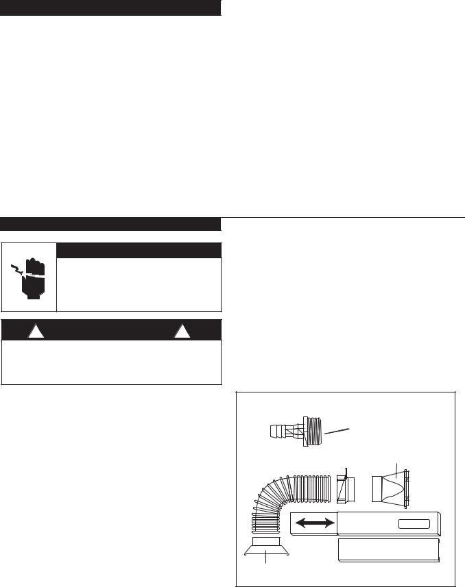
Installation Accessories |
Fig.1 |
Description |
Quantity |
Flexible exhaust hose with adapters..........3/set stretches from 191/2" (50cm) up to
783/4" (200cm)
Window exhaust adapter(flat mouth)...........1Pc
Adjustable window/patio door slider kit......2/set from265/8" (67.5cm) up to
483/8"(203cm)
Drain hose connector.........................1 Pc continuous drain option (hose not included)
SPECIAL NOTE: Exterior drain hose extension (direct drain) is not included with this unit and can be purchased through any local Hardware Store.
The exhaust/window kit must be installed at all times when the unit is operating under the AIR CONDITIONING mode.
There should be at least 11.8"(30 cm) clearance between the unit and any other other objects or building structure. The unit should be installed on a level surface. The window kit does not have to be
installed during operation of the remaining three modes. (Heating/Dehumidifying/Fan).
Fig. 1 Installation Accessories |
|
|
|
|
|
|
|
||||||
|
|
|
|
|
|
Drain Hose Connector |
|||||||
Flexible Exhaust Hose |
Window Exhaust |
||||||||||||
|
Adapter |
||||||||||||
19 |
1 |
/2"- 78 |
3 |
/ |
4" |
Adapter |
|
||||||
|
|
|
|
|
|
|
|
|
|||||
|
|
|
|
|
|
|
|
|
|
|
|
|
|
Adapter |
|
|
|
Adjustable Window/Patio Door Slider Kit |
|||||||||
|
|
|
|
|
|
Adjustable Window/Patio Door Slider Kit |
|||||||
|
|
|
|
|
|
265/8" - 48 |
3/8” 5 |
/ |
8" |
- 48 |
3 |
/ |
” |
|
|
|
|
|
|
|
26 |
|
|||||
|
|
|
|
|
|
|
|
|
|
|
8 |
" |
|
4
Window Kit Installation
Your window kit has been designed to fit most
standard "vertical"and "horizontal" window
applications. However, it may be necessary for
you to improvise/modify some aspects of the
installation procedures for certain types of
windows. Please refer to Fig. 2 & Fig. 2a for minimum and maximum window openings.
Water Tank Safety Feature
This unit is equipped with a fail-safe switch mechanism which prevents the unit from condensing water in the event the water tank is accidentally displaced, and/or FULL with water. If this situation occurs, the unit will signal 8 BEEPS and the
WATER FULL indicator light will flash red continuously until the water tank is correctly positioned and/or emptied.
NOTE: The fan motor will continue to operate under this condition. This is normal, but no cooling or dehumidifying will occur until the tank is emptied and/or correctly installed (It may take several minutes before the compressor resumes normal operation).
Horizontal Window |
|
Window Slider Kit |
|
Minimum: 265/8"(67.5 cm ) |
Fig. 2 |
Maximum: 483/8"(123cm) |
|
Vertical |
Window |
Fig. 2a
Window Slider Kit Minimum: 265/8"(67.5 cm ) Maximum: 483/8"(123cm)
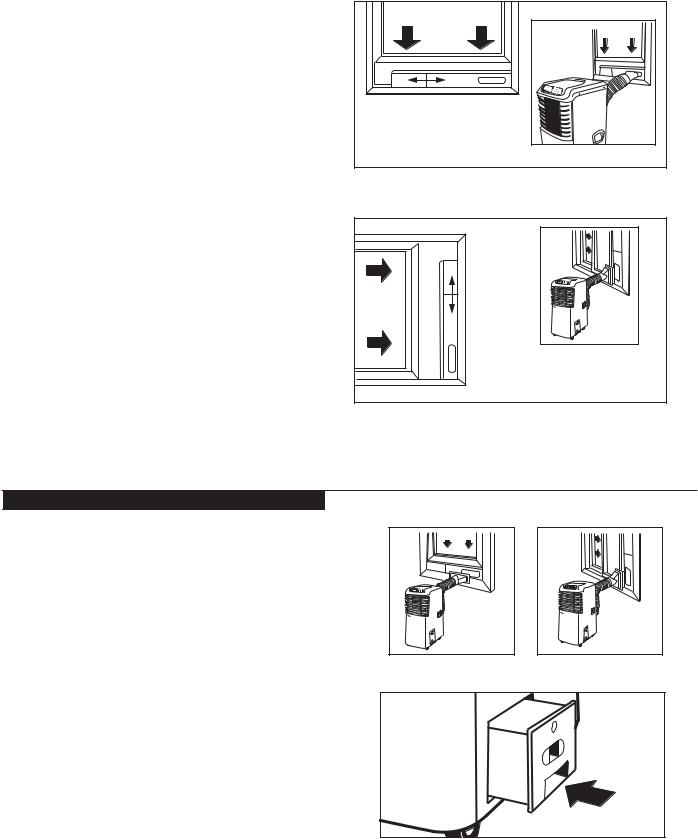
Window Installation
Before Starting This Unit
1) Select a suitable location, making sure you have
easy access to an electrical outlet.
2) Install the Flexible Exhaust Hose and the
Adjustable Window Slider Kit as depicted in
Fig. 3 & Fig. 3a. |
Fig. 3 |
Fig. 3a |
|
NOTE: Step 2 is required only while using the
AIR CONDITIONER MODE
3)Plug the unit into a 115V/60Hz grounded electrical outlet.
DO NOT USE AN EXTENSION CORD.
4)Make sure the Water Tank is correctly positioned inside the cabinet otherwise the unit will not
operate. Fig 4. |
Fig. 4 |
5)To turn the unit on, press the I/O key (On/ Off Switch).
5
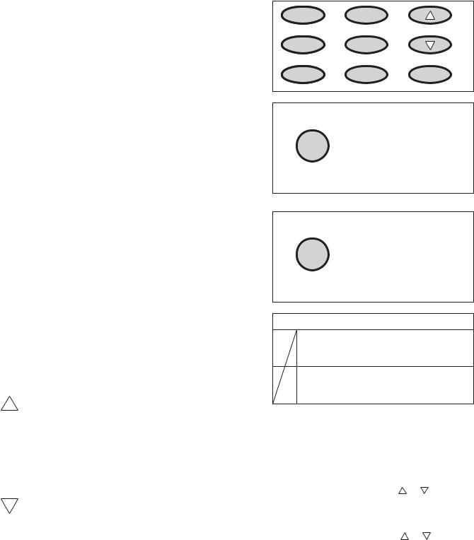
Key Pad Functions Fig.5
I/O: Power On/Off.
MODE: Selects the appropriate operating mode.
Cool-Heat-Dry (Dehumidifier)-Fan.
Note:"Heat Mode" is for Heating/Cooling Model
only .
MODE Indicator Lights: Illuminates under the
different mode settings Fig.6;
COOL Mode: |
Green Light |
HEAT Mode: |
Red light |
DRY(Dehumidifier)Mode: |
Green Light |
FAN Mode: |
No indicator light |
Green Light : Remains on while compressor is operating. Green light turns off when desired temperature is achieved. Applicable to both
Air Conditioner and Dehumidifier.
Red Light: Remains on while heater is operating. Red light turns off when desired temperature is achieved.
Water Full Indicator Light: Flashes red when the water level of the water tank exceeds the maximum set level or if the water tank is not correctly positioned in the cabinet. Fig.7.
FAN: Selects High-Medium-Low fan speeds
Fan Options:
Cooling (3 speeds) High-Medium-LOW.
Heating (2 speeds) High-Low.
Dry-Dehumidifying (1 speed) Medium.
Fan (3 speeds) High-Medium-Low.
:Used to adjust (forward ) Time of Day Clock settings (1min, increments).
Used to adjust (forward) Temperature settings (1oC increments).
Used to adjust (forward) Auto-Timer of settings (10 min. increments)
:Used to adjust (backward ) Time of Day Clock settings (1min, increments).
Used to adjust (backward) Temperature settings (1oC increments).
Used to adjust (backward) Auto-Timer of settings (10 min. increments)
SWING: Allows the vertical louver grills
to oscillate back and forth automatically(70o Swing).
CLOCK: Allows you to initiate and/or change the
TIME OF DAY setting.
I/O MODE
FAN |
ON |
|
|
TIMER |
|
SWING |
OFF |
CLOCK |
Fig.5
Green light while cooling
Red light while heating
Green light while dehumidifying
Cool/Heat/Dry
Fig.6
A warning signal of 8 beeps will sound and the Water Full indicator will flash every
0.5 seconds.
Water Full
Fig.7
Temperature Conversion Chart
OC 10 11 12 13 14 15 16 17 18 19 20 21
OF 50 52 54 55 57 59 61 63 64 66 68 70
OC 22 23 24 25 26 27 28 29 30 31 32 33
OF 72 73 75 77 79 81 82 84 86 88 90 91
TIMER ON: Used to initiate the AUTO ON start time
program, in conjuction with the & key pads
TIMER OFF: Used to initiate the AUTO OFF stop time program, in conjuction with the & key pads.
6

Setting TIME OF DAY (Clock) Instructions: |
|
|
|
|
|
|
|
|
|
|||
1) Push and hold the CLOCK key pad for three(3) |
|
|
12:00 |
|
|
l/0 |
MODE |
|
||||
|
|
|
|
|
|
|
|
|
|
|
||
seconds. The clock display will flash indicating |
|
|
|
|
|
|
FAN |
ON |
|
|||
"12.00" for approximately 10 seconds. |
|
|
|
|
|
|
|
TIMER |
|
|||
|
|
|
|
|
|
SWING |
OFF |
CLOCK |
||||
Fig.8. |
|
|
|
|
|
|
|
|
|
|
|
|
2) Push either the |
or |
key pad, to enter the |
|
|
|
|
|
|
|
|
|
|
correct time of day. Each depression of the key pad |
|
|
|
|
|
|
|
|
Fig. 8 |
|||
will increase or decrease the time of day |
|
|
|
|
|
|
|
|
|
|||
setting (1 minute increments). Fig. 9. |
|
|
|
|
|
|
|
|
|
|||
|
|
|
|
|
|
12:01 |
|
|
l/0 |
MODE |
|
|
3) When the correct time of day has been |
|
|
|
|
|
|
|
|||||
|
|
|
|
|
|
|
|
|
||||
established in the display window, push the |
|
|
|
|
|
|
FAN |
ON |
|
|||
|
|
|
|
|
|
|
TIMER |
|
||||
CLOCK key pad again to activate the TIME OF |
|
|
|
|
|
|
SWING |
OFF |
CLOCK |
|||
|
|
|
|
|
|
|
|
|
||||
DAY clock setting. The "colons" between the |
|
|
|
|
|
|
|
|
|
|||
TIME OF DAY will start to flash indicating the |
|
|
|
|
|
|
|
|
Fig. 9 |
|||
|
|
|
|
|
|
|
|
|
|
|
|
|
clock is operational. |
|
|
|
|
|
|
|
|
|
|
|
|
Important Note: Any interruption to the electrical |
|
|
|
|
|
DUCT |
|
|
||||
|
|
|
|
|
|
|
|
|
|
|
||
power supply will automatically cancel the TIME |
|
Duct |
Exhaust Air Outlet |
|
|
|
||||||
OF DAY clock program. In the event this should |
|
|
|
|
|
|
|
|
|
|||
happen, you will be required to re-set the |
|
|
|
|
|
|
|
|
|
|||
clock program. |
|
|
|
|
|
|
|
|
|
|
|
|
Air Conditioner Operating Instructions |
|
Fig. 10 |
|
|
|
|
|
|
|
|||
|
|
|
|
|
|
|
|
|
||||
1) Install the Flexible Exhaust Hose Fig.10 and |
|
|
|
|
|
|
|
|
|
|||
the Adjustable Window/Patio Door Slider Kit |
|
|
|
|
|
|
12:00 |
l/0 |
MODE |
|||
as depicted in Fig.2,2a & 2b (pg.5) |
|
|
TIMER |
ON |
|
|
||||||
Water Full |
|
MODE |
COOL |
|
|
|
||||||
|
|
|
|
|
|
|
|
|
|
|
|
ON |
2) Press the I/O (on/off )key pad to switch on the |
|
|
FAN SPEED |
|
HIGH |
00 |
|
TIMER |
||||
|
|
|
|
|
TEMP. |
|
||||||
|
|
|
|
Cool/Heat/Dry |
|
|
|
|
|
|
|
OFF |
unit. |
|
|
|
|
|
|
|
|
|
|
|
|
|
|
|
|
Green Light |
Air Conditioner |
|
|
|||||
3) Press the MODE key until the word COOL is |
|
|
|
Fig. 12 |
||||||||
|
|
|
Mode |
|
|
|||||||
|
|
|
|
|
|
|
|
|
|
|||
displayed in the LCD (Liquid Crystal Display) |
|
|
|
|
|
|
|
|
|
|||
window.Fig.12. Each depression of the MODE |
|
|
|
|
|
|
|
|
|
|||
key will advance to a different mode setting |
TIMER |
ON |
12:00 |
l/0 |
MODE |
|
||||||
|
|
|
||||||||||
|
|
|
|
MODE |
COOL |
|
|
|
|
FAN |
ON |
|
(Cool-Heat-Dry-Fan). |
|
|
|
|
|
|
|
|
|
|||
|
|
FAN SPEED HIGH |
|
|
|
|
TIMER |
|
||||
|
|
|
|
|
|
|
|
|
|
|
|
|
|
|
|
|
|
|
TEMP. |
|
o |
|
|
|
|
Note: Heat is for Heating/Cooling Model only. |
|
|
17 c |
SWING |
OFF |
CLOCK |
||||||
|
|
|
||||||||||
|
|
|
|
|
|
|
|
|
||||
4) Press the appropriate |
or |
key to select a |
|
|
|
|
|
|
|
|
|
|
suitable temperature setting. The temperature |
Temperature |
|
|
|
|
|
|
|||||
|
|
|
|
|
|
|
|
Fig. 13 |
||||
|
|
|
|
|
|
|
|
|
|
|
|
|
selected will be indicated in the |
|
|
|
|
|
|
|
|
|
|||
LCD (Liquid Crystal Display) window. |
|
|
|
|
|
|
|
|
|
|||
Temperature settings are adjustable between |
|
|
|
|
|
|
|
|
|
|||
17oC(63oF)to 30oC(86oF). Fig.13. |
|
|
|
|
|
|
|
|
|
|||
The green indicator light will come on indicating the |
|
|
|
|
|
|
|
|
|
|||
air-conditioning mode is operational (there may be a |
|
|
|
|
|
|
|
|
|
|||
slight delay of 10-30 seconds before the cycle |
|
|
|
|
|
|
|
|
|
|||
begins, this is normal). |
|
|
|
|
|
|
|
|
|
|
|
|
7
 Loading...