

Page 1

Item #541-903
Model #MEF2823CBWLG
USE AND CARE GUIDE
EVANS ELECTRIC FIREPLACE
Questions, problems, missing parts? Before returning to the store call
We appreciate the trust and condence you have placed in Hampton Bay through the purchase of this Electric Fireplace.
We strive to continually create quality products designed to enhance your home. Visit us online to see our full line of
products available for your home improvement needs. Thank you for choosing Hampton Bay!
Hampton Bay Customer Service
8 a.m. - 6 p.m., EST, Monday-Friday
1-877-527-0313
HOMEDEPOT.COM
THANK YOU
Page 2

Table of Contents
Table of Contents ...................................2
Safety Information ..................................2
Warranty ..........................................3
Pre-Assembly ......................................4
Safety Information
1. Read all instructions before using this replace.
2. This replace is hot when in use. To avoid burns,
do not let bare skin touch hot surfaces. If provided,
use handles when moving this replace. Keep
combustible materials, such as furniture, pillows,
bedding, papers, clothes, and curtains at least 3 feet
(0.9 meters) from the front of the replace and keep
them away from the sides and rear.
3. Extreme caution is necessary when any replace is
used by or near children or invalids and whenever
the heater is left operating and unattended.
4. Always unplug the replace when not in use.
5. Do not operate any replace with a damaged cord
or plug or after the replace malfunctions, has been
dropped, or is damaged in any manner. Return
the replace to an authorized service facility for
examination, electrical or mechanical adjustment, or
repair.
6. Do not use outdoors.
7. This replace is not intended for use in bathrooms,
laundry areas, and similar indoor locations. Never
locate the replace where it may fall into a bathtub or
other water container.
8. Do not run the power cord under carpeting. Do not
cover the power cord with items such as throw rugs
or runners. Arrange the power cord away from trafc
areas to ensure that it is not tripped over.
9. To disconnect the replace, turn the controls to the
off position and remove the plug from the outlet.
10. Connect to properly grounded outlets only.
11. Do not insert or allow foreign objects to enter any
ventilation or exhaust openings as this may cause
an electric shock or re, or damage the replace.
Assembly. . . . . . . . . . . . . . . . . . . . . . . . . . . . . . . . . . . . . . . . . . 6
Operation. . . . . . . . . . . . . . . . . . . . . . . . . . . . . . . . . . . . . . . . . 10
Care & Cleaning ...................................11
Service Parts ......................................11
12. To prevent a possible re, do not block rebox
air intakes or the exhaust in any manner. Do not
operate the replace on soft surfaces, like a bed,
where openings may become blocked.
13. A replace has hot and arching or sparking parts
inside. Do not use in areas where gasoline, paint,
or ammable liquids are used or stored.
14. Use this replace only as described in this manual.
Any other use not recommended by the manufac-
turer may cause re, electrical shock, or injury to
persons.
15. Avoid the use of an extension cord because the
extension cord may overheat and cause a risk
of re. However, if you have to use an extension
cord, the cord shall be No.14ga minimum size and
rated not less than 1875 watts.
NOTE: Save these instructions.
2
Page 3

Warranty
LIMITED WARRANTY
The supplier warrants this product to be free from defects in material and workmanship, under normal use and
service, for one (1) year (1 year limited parts) from the date of purchase.
All warranty repairs must be pre-authorized by the supplier. The supplier will, at its option, replace or repair free of
charge any defective part, which the purchaser shall notify their distributor or the supplier within the warranty period.
The obligation of the supplier under this warranty, is expressly limited to such replacement or repairs.
The provisions of this limited warranty shall not apply to the following:
1. Accidents.
2. Unauthorized repairs or alterations.
3. Normal maintenance.
4. Changes made to other units manufactured after this replace insert was manufactured.
5. Incidental damages caused by failure of the replace insert such as inconvenience or loss of use.
6. Improper installation.
The provisions of this limited warranty shall not apply to deterioration due to wear and exposure beyond the
following limitations:
1. For one (1) year from the date of purchase on electrical component and circuit boards (light bulbs excluded).
The supplier Limited Warranty is void unless the following conditions are adhered to:
1. Warranty registration must be completed and returned to the supplier.
2. All warranty repairs must be preauthorized by the supplier’s repair facility.
3. The supplier reserves the right to inspect defective parts that have been replaced under warranty.
The distributor is expected to hold defective parts for 60 days.
4. Only parts and accessories and other material, available through the supplier, are to be used in the performance
of warranty service.
5. Purchasers are responsible for presenting/notifying their distributor as soon as a problem exists. The warranty
repairs should be completed in a reasonable amount of time from the date of authorization. Not to exceed 30
days past notication.
This limited warranty is expressly in lieu of any other expressed or implied warranty, including any implied warranty
or merchantability or tness for a particular purpose and of any obligations or liabilities on the supplier which neither
assumes nor authorizes any other person to assume for it any other liability in connection with the replace insert
manufactured by it.
The warranty is null and void if used in commercial or industrial applications.
Contact the Customer Service Team at 1-877-527-0313 or visit www.homedepot.com.
3 HOMEDEPOT.COM
Please contact 1-877-527-0313 for further assistance.
Page 4

Pre-Assembly
PLANNING ASSEMBLY
Before you begin assembly, locate the instructions and hardware. Take out all the parts and compare them to the
diagrams below. Be sure you have all the parts and can identify them. A helping hand is always good. Assemble
your mantel with an adult assistant if possible. Some pieces are heavy and will need to be held by a helper.
Assembly time will take approximately 30-60 minutes.
Before assembly, use scissors to unwrap the parts from the packaging. Do not use a box cutter or exacto-knife as
you may cut into the mantel pieces inside the box and damage the nish. Check for the Red hardware bag located
inside the packaging, taped to the top of the box. Do not discard any pieces. Use an appropriate screwdriver to
insert and tighten all screws.
TOOLS REQUIRED
Safety
goggles
Phillips
screwdriver
HARDWARE INCLUDED
NOTE: Hardware shown to actual size.
GGFFEE
Part Description Quantity
AA Wood Dowel 22
BB Bolt 28
DDCCBBAA
HH II
JJ
KK
CC Washer 28
DD Screw 2
EE Mounting Bracket 4
FF Wall Anchor 4
GG Nylon Strap (not to size) 2
HH Small Screw 4
II Large Screw 4
JJ Firebox Support 1
KK Touch-Up Pen (not to size) 1
4
Page 5
Pre-Assembly (continued)
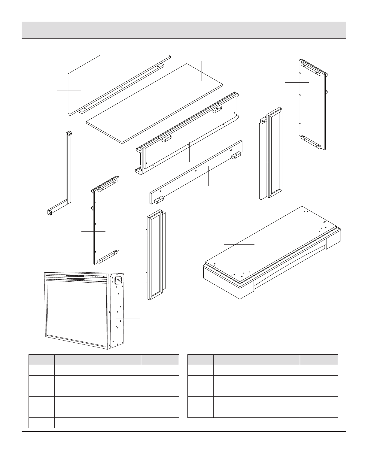
PACKAGE CONTENTS
I
H
B
F
E
J
G
C
D
A
K
Part Description Quantity
A Base 1
B Right Side Panel 1
C Left Side Panel 1
D Left Front Panel 1
E Right Front Panel 1
F Upper Front Horizontal Panel 1
5 HOMEDEPOT.COM
Please contact 1-877-527-0313 for further assistance.
Part Description Quantity
G Lower Front Horizontal Panel 1
H Top 1
I Corner Option Piece 1
J Corner Brace 1
K Firebox Insert 1
Page 6
Assembly
1
2
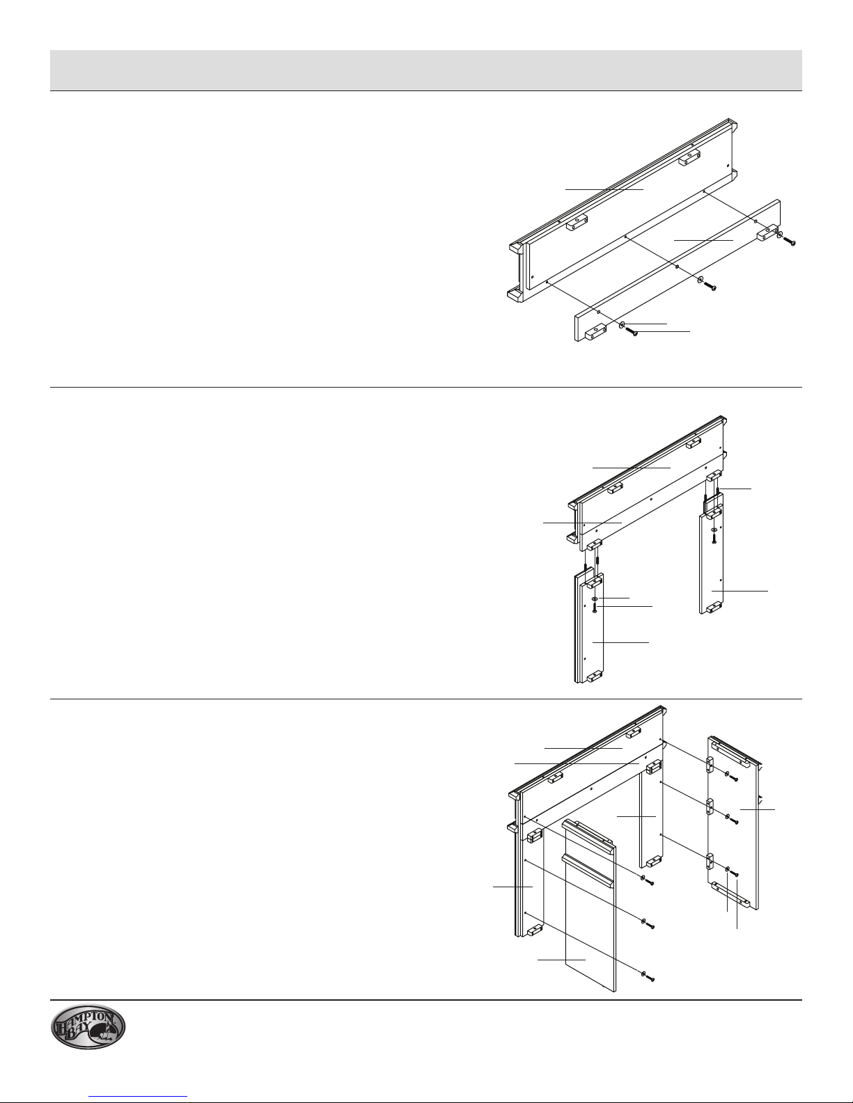
Assembling the top front panels
□ Align the holes in the upper front horizontal panel (F) with
the holes on the top of the lower front horizontal panel (G).
□ Insert one large bolt (BB) and washer (CC) into each hole on
the lower front horizontal panel (G) and securely tighten. Do
not strip the bolts by overtightening.
Assembling the front panels
□ Insert four wood dowels (AA) into the holes in the blocks on
the bottom edge of the lower front horizontal panel (G).
□ Align the holes in the top of the right front panel (E) with
the wood dowels (AA) on the right side of the lower front
horizontal panel (G) and push down until ush.
□ Insert one large bolt (BB) and washer (CC) into the hole in
the block on the right front panel (E) and securely tighten.
Do not strip the bolts by overtightening.
□ Repeat these steps for the left front panel (D).
F
G
CC
BB
F
AA
G
CC
BB
E
D
3
6
Assembling the side panels
□ Locate the left side panel (C).
□ Align the holes in the mantel assembly with the holes in the
left side panel (C).
□ Insert one large bolt (BB) and one washer (CC) into each
of the three holes in the three blocks on the left side
panel (C) securing the left side panel (C) to the mantel
assembly. Tighten until secure. Do not strip the bolts by
overtightening.
□ Repeat for the right side panel (B).
F
G
D
E
CC
BB
B
C
Page 7
Assembly (continued)
4
5
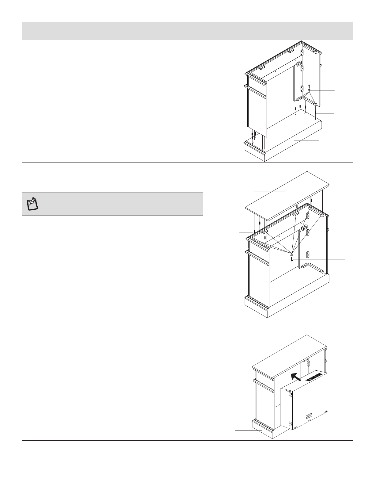
Attaching the panels to the base
□ Locate the base (A).
□ Insert eight wood dowels (AA) into the holes on the base.
□ Align the holes on the bottom edge of the mantel assembly
with the wood dowels (AA) in the base. Push down until
ush.
□ Insert one large bolt (BB) and one washer (CC) into each of
the six holes in the four blocks at the bottom of the mantel
assembly. Tighten until secure. Do not strip the bolts by
overtightening.
Attaching the top
NOTE: This top is heavy. It is recommended that you use
two people at this stage to prevent damage to the top of the
mantel assembly.
□ Locate the top (H) and place with the nished side down on
a clean dry surface.
□ Insert six wood dowels (AA) into the holes on the bottom of
the top (H).
□ Turn the top (H) over and ensure the nished side is facing
up. Align the holes on the top of the mantel assembly with
the wood dowels (AA) on the underside of the top (H). Push
down until ush.
□ Insert one large bolt (BB) and one washer (CC) into
each of the six holes in the four blocks on the top of
the mantel assembly attaching the top (H) to the mantel
assembly. Tighten until secure. Do not strip the bolts by
overtightening.
AA
AA
BB
CC
AA
A
H
AA
CC
BB
6
7 HOMEDEPOT.COM
Please contact 1-877-527-0313 for further assistance.
Inserting the rebox
□ Locate the rebox insert (K).
□ Insert the rebox into the mantel from the rear. Be very
careful not to scratch the base (A).
□ Viewing from the front of the mantel, ensure that the rebox
insert (K) is in the center of the opening.
K
A
Page 8
Assembly (continued)
7
8
The rebox comes with three metal trim pieces and 11 black
screws (10 pcs + 1 spare). These metal trim pieces must be
attached to all three sides of the rebox and to two sides of the
mantel to ensure that your rebox does not move around as
you use it. Refer to your rebox manual for instructions on how
to attach the rebox trim pieces.
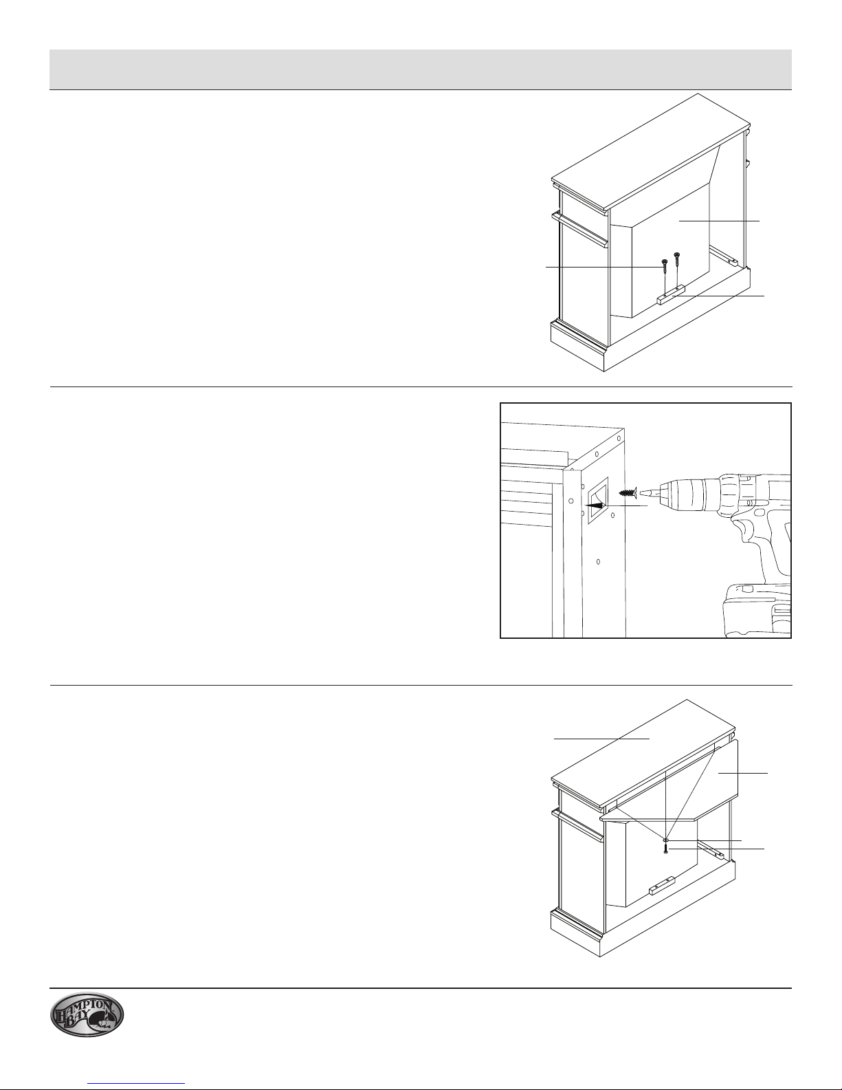
Securing the rebox
□ Locate the rebox support (JJ) and place it snuggly behind
the rebox insert (K) to hold it in position. Do not cover any
air venting.
□ Insert two screws (DD) into the holes in the rebox support
(JJ) and through to the base (A). Tighten until secure.
Firebox trim pieces
K
DD
JJ
9
8
Attaching the corner option piece
□ Locate the corner option piece (I). Align the holes on the
mantel top (H) with the holes on the corner option piece (I).
□ Insert one large bolt (BB) and one washer (CC) into each of
the three holes on the corner option piece (I) attaching it to
the top (H). Tighten until secure. Do not strip the bolts by
overtightening.
H
I
CC
BB
Page 9

Assembly (continued)
10
Attaching the corner brace
□ Locate the corner brace (J). Insert two wood dowels (AA)
into the top and bottom of the corner brace (J).
□ Align the holes in the corner option piece (I) and the base
(A) with the wood dowels (AA) in the corner brace (J). Push
in until ush.
□ Insert one large bolt (BB) and one washer (CC) into the hole
at each end of the corner brace (J). Tighten until secure. Do
not strip the bolts by overtightening.
Attaching the anti-tip device
11
to the mantel
WARNING: Young children may be injured by tipping
furniture. The use of a tipping restraint is highly
recommended. This hardware, when properly installed,
could provide protection against the unexpected
tipping of furniture due to improper use.
I
CC
BB
J
A
AA
EE
HH
□ Attach one of the mounting brackets (EE) securely to the
back edge of the mantel. Use the small screws (HH) to
secure.
NOTE: If using the corner option piece, mounting brackets
must be placed on both edges that touch the walls.
9 HOMEDEPOT.COM
Please contact 1-877-527-0313 for further assistance.
Page 10

Assembly (continued)
Attaching the anti-tip device
12
□ Determine the location of the replace and mark the
location on the wall for the other mounting bracket screw
holes (II). Using a drill or screwdriver, make holes in the wall
where marked.
□ If you are attaching to drywall or plaster, insert a wall
anchor (FF) into each hole in the wall.
□ Position the mounting bracket (EE) over the holes in the
wall and use the large screws (II) to securely attach the
mounting bracket (EE) to the wall.
13
to the wall
Securing the anti-tip device
WARNING: This product is only a deterrent. It is not a
substitute for proper adult supervision.
FF
EE
II
II
WALL
EE
□ Place the mantel so the mounting bracket (EE) on the back
edge is in alignment with the mounting bracket (EE) on the
wall.
□ Place an end of the nylon strap (GG) down through each
mounting bracket (EE). Bring both ends together and slide
the end of the nylon strap (GG) through the slot in the other
end until snug. Pull down on the end until it snap locks into
the slot.
□ Check to ensure the nylon strap (GG) is securely laced and
locked to the mounting brackets (EE).
Operation
Refer to your rebox insert manual for operation instructions.
GG
DD
MANTEL
10
Page 11

Care and Cleaning
□ Dust your replace mantel regularly with a soft non-lint producing cloth or household dusting product.
□ Clean your replace insert with a gentle non-abrasive household cleaner. Dry your replace immediately
with a soft cloth or towel.
Service Parts
H
B
I
F
J
C
K
Part Description Part Number
A Base ZZ.2823CBWLG.01
B Right Side Panel ZZ.2823CBWLG.02
E
G
D
E
A
Part Description Part Number
Lower Front Horizontal Panel
G
ZZ.2823CBWLG.07
H Top ZZ.2823CBWLG.08
C Left Side Panel ZZ.2823CBWLG.03
D Left Front Panel ZZ.2823CBWLG.04
E Right Front Panel ZZ.2823CBWLG.05
Upper Front Horizontal Panel
F
11 HOMEDEPOT.COM
Please contact 1-877-527-0313 for further assistance.
I Corner Option Piece ZZ.2823CBWLG.09
J Corner Brace ZZ.2823CBWLG.10
K Firebox Insert MFB28-3
ZZ.2823CBWLG.06
Page 12

Artículo #541-903
Modelo #MEF2823CBWLG
GUIA DE USO Y MANTENIMIENTO
REPISA DE CHIMENEA ELECTRICA EVANS
¿Preguntas, problemas, le faltan piezas? Antes de devolver el producto a la tienda llame a:
Agradecemos la conanza que ha depositado en Hampton Bay a través de la compra de esta Chimenea Eléctrica.
Nos esforzamos continuamente para crear productos de calidad diseñados para mejorar su hogar. Visítenos en línea para
ver nuestra línea completa de productos disponibles para sus necesidades de mejoras para
Servicio al Cliente Hampton Bay
8 a.m. - 6 p.m., EST, Lunes- Viernes
1-877-527-0313
HOMEDEPOT.COM
GRACIAS
el hogar. Gracias por elegir Hampton Bay!
Page 13

Tabla de Contenido
Tabla de Contenido .................................13
Información de Seguridad ...........................13
Garantía. . . . . . . . . . . . . . . . . . . . . . . . . . . . . . . . . . . . . . . . . . 14
Pre-Ensamblaje ...................................15
Información de Seguridad
1. Lea todas las instrucciones antes de usar este
calefactor.
2. Cuando está en uso, este calefactor se calienta. Para
evitar quemaduras, no toque las supercies calientes
con la piel desnuda. Cuando mueva este calefactor,
utilice agarraderas, si se le suministraron. Mantenga
materiales inamables, como muebles, almohadas,
ropa de cama, papeles, ropa y cortinas, a una
distancia mínima de 3 pies (0.9 metros) de la parte
delantera del calefactor. Mantenga estos materiales
alejados también de los laterales y de la parte trasera
del calefactor.
3. Es necesario tener especial cuidado cuando niños
o inválidos usan el calefactor, o cuando se usa
cerca de ellos, y cuando el calefactor se deja en
funcionamiento sin supervisión.
4. Cuando el calefactor no está en uso, desconéctelo.
5. No encienda el calefactor si el cable o el enchufe
está dañado, si se produjo una falla en el
funcionamiento, si se cayó o si está dañado de
alguna forma. Para una revisión, ajustes mecánicos
o élctricos o una reparación, lleve el calefactor a un
centro de servicio técnico autorizado.
6. No lo utilice al aire libre.
7. Este calentador no está destinado para ser usado
en baños, lavandería y áreas similares en lugares
cerrados. Nunca ubicar el calentador donde pueda
caer en una bañera u otro recipiente de agua.
8. No pase el cable de alimentación por debajo del
alfombrado. No cubra el cable de alimentación con
alfombras pequeñas o similares. Coloque el cable
de alimentación lejos de las áreas transitadas y en
donde nadie tropezará con él.
9. Para desconectar el calefactor, coloque los controles
en la posición de apagado y, luego, retire el enchufe
del tomacorriente.
Ensamblaje .......................................17
Operación ........................................21
Cuidado & Mantenimiento ...........................22
Piezas de Servicio .................................22
10. Conecte sólo a tomacorrientes que tengan una
conexión a tierra adecuada.
11. No introduzca ni permita que entren objetos extraños en las aperturas de ventilación o del sistema
de escape, ya que esto puede generar incendios o
descargas eléctricas, o dañar el calefactor.
12. Para prevenir posibles incendios, no tape las tomas de aire ni el sistema de escape. No lo utilice
sobre supercies mullidas, como una cama, en las
que pueden taparse las aperturas.
13. Un calefactor tiene partes internas calientes,
arqueadas y que despiden chispas. No lo utilice
en áreas en las que se usan o almacenan combustibles, pinturas o líquidos inamables.
14. Use este calefactor sólo como se describe en este
manual. Cualquier otro uso no recomendado por
el fabricante puede ocasionar incendios, descargas eléctricas o daños a personas.
15. No utilice extensiones, ya que podrían recalentarse y generar riesgo de incendios. Sin embargo,
si fuera necesario usar una extensión, éste debe
ser, como mínimo, el Nº 14ga, de no menos de
1875 vatios.
NOTA: Guarde estas instrucciones.
13 HOMEDEPOT.COM
Por favor contacte 1-877-527-0313 para más asistencia.
Page 14

Garantía
GARANTÍA LIMITADA
El surtidor le garantiza al comprador que el Inserto eléctrico estará libre de defectos en material y mano de obra,
bajo uso y servicio normal, por uno (1) año (1 año para componentes limitados) a partir de la fecha de compra.
El surtidor deberá autorizar previamente todas las reparaciones bajo garantía. A su consideración, el surtidor,
reemplazará o reparará sin costo cualquier componente defectuoso, después de que el comprador se lo informe
a su Distribuidor o a el surtidor, dentro del periodo de garantía. Bajo esta garantía, la obligación de el surtidor está
limitada expresamente al tal reemplazo o reparación.
Los términos de esta garantía limitada no son aplicables a lo siguiente:
1. Accidentes.
2. Reparaciones o modicaciones no autorizadas.
3. Mantenimiento normal.
4. Modicaciones que se ejecutaron en otras unidades fabricadas después de fabricar este Inserto para
chimenea.
5. Daños incidentales causados por fallas del Inserto eléctrico tal como molestias o pérdida del uso.
6. Instalación incorrecta.
Los términos de esta garantía no son aplicables al deterioro debido al desgaste y exposición más allá de las
limitaciones siguientes:
1. Componentes eléctricos y placas de circuito por un (1) año después de la fecha de compra (las bombillas se
excluyen).
La garantía limitada el surtidor no tiene validez salvo que se acepten las condiciones siguientes:
1. El registro de garantía debe ser llenado y mandado el surtidor.
2. Todas las reparaciones dentro de la garantía deben estar pre-autorizadas por el proveedor.
3. El surtidor se reserva el derecho de inspeccionar los componentes defectuosos que se hubiesen reemplazado
bajo la garantía. El distribuidor deberá conservar los componentes defectuosos durante 60 días.
4. Para cumplir debidamente con la garantía, se deberán utilizar solamente componentes, accesorios y otros
materiales disponibles a través de el surtidor.
5. Es responsabilidad de los compradores el presentarse o informar al distribuidor tan pronto como se suscite un
problema. Las reparaciones bajo la garantía deberán llevarse a cabo en un plazo razonable después de la fecha
de la autorización. No deberá sobrepasar más de 30 días después de la noticación.
Esta garantía sustituye expresamente cualquier otra garantía expresada o implícita, incluida cualquier garantía
implícita o de comercialización o idoneidad para algún propósito en particular y de cualesquiera otras obligaciones
o limitaciones de el surtidor, el cual no acepta ni autoriza que ninguna otra persona acepte por ella ninguna otra
responsabilidad en lo que se reere al inserto de chimenea fabricado por la misma.
Esta garantía se tornará nula y quedará sin efecto si se utiliza en aplicaciones comerciales o industriales.
Contacte el departamento de Servicio al Cliente a 1-877-527-0313 o visite www.homedepot.com.
14
Page 15

Pre-Ensamblaje
PLANEANDO EL ENSAMBLAJE
Antes de comenzar el ensamblaje, localice las instrucciones y los accesorios. Saque todas las piezas y compárelas
con los diagramas que aparecen a continuación. Asegúrese de tener todos los componentes y que puede identicarlos. De ser posible pida la ayuda de otro adulto para ensamblar este producto. Algunas piezas son pesadas y necesitará de un ayudante para que las sostenga. El tiempo de ensamble tomará de 30 a 60 minutos aproximadamente.
Antes del montaje utilice tijeras para desenvolver las piezas del embalaje. NO use una navaja o un cuchillo multi-
uso, pues podría dañar las piezas del mueble dentro de la caja y dañar el acabado. Compruebe que la bolsa de accesorios, que es de color rojo se encuentre dentro del embalaje, adherida a la parte superior de la caja. NO deseche
ninguna pieza. Utilice el destornillador apropiado para insertar y ajustar los tornillos.
HERRAMIENTAS QUE NECESITARÁ
Espejuelos
de seguridad
Destornillador
Phillips
FERRETERIA INCLUIDA
NOTA: Ferretería se muestra a tamaño original.
DDCCBBAA
GGFFEE
Pieza Descripción Cantidad
AA Espiga de madera 22
BB Perno 28
HH II
JJ
KK
CC Arandela 28
DD Tornillo 2
EE Soporte de montaje (no se muestra en tamaño real) 4
FF Ancla de expansión de pared (no se muestra en tamaño real) 4
GG Correa de nailon (no se muestra en tamaño real) 2
HH Tornillo pequeño 4
II Tornillo grande 4
JJ Soporte de la Caja de Fuego (no se muestra en tamaño real) 1
KK Pluma de retoque (no se muestra en tamaño real) 1
15 HOMEDEPOT.COM
Por favor contacte 1-877-527-0313 para más asistencia.
Page 16

Pre-Ensamblaje (continuado)
CONTENIDO DEL PAQUETE
I
H
B
F
E
J
G
C
D
A
K
Pieza
16
Descripción Cantidad
A Base 1
B Panel Lateral Derecho 1
C Panel Lateral Izquierdo 1
D Panel Delantero Izquierdo 1
E Panel Delantero Derecho 1
Panel Frontal Superior Horizontal
F
Pieza
1
Descripción Cantidad
Panel Frontal Horizontal Inferior
G
H Panel Superior 1
I Pieza Opcional de Esquina 1
J Soporte de Esquina 1
K Caja de Fuego 1
1
Page 17

Ensamblaje
Ensamblado de los paneles
1
2
frontales superiores
□ Alinee los oricios en el panel frontal superior horizontal
(F) con los agujeros en la parte superior del panel frontal
horizontal inferior (G).
□ Inserte un tornillo grande (BB) y la arandela (CC) en cada
oricio en el panel frontal inferior horizontal (G) y apriete
bien. No vaya a dañar los tornillos por apretar demasiado.
Ensamblado de los paneles
frontales
□ Inserte 4 pasadores de madera (AA) en los oricios en los
bloques en el borde inferior del panel delantero (G).
□ Alinee los oricios en la parte superior del panel frontal
derecho (E) con los pasadores de madera (AA) en el lado
derecho del panel frontal (G) y empuje hacia abajo hasta
que quede nivelado.
□ Inserte un perno grande (BB) y una arandela (CC) en el
oricio en el bloque en el panel frontal derecho (E). Ajuste
hasta que quede rme. No dañe los tornillos por apretar
demasiado.
□ Repita el procedimiento para el panel frontal izquierdo (D).
F
G
CC
BB
F
AA
G
CC
BB
E
D
3
17 HOMEDEPOT.COM
Por favor contacte 1-877-527-0313 para más asistencia.
Ensamblando los paneles laterales
□ Localice el panel lateral izquierdo (C).
□ Alinee los oricios en la repisa ensamblada con los oricios
en el panel lateral izquierdo (C).
□ Inserte un perno grande (BB) y una arandela (CC) en cada
uno de los 3 oricios en los 3 bloques en el conjunto
ensamblado jando el panel lateral izquierdo (C) a la repisa
de chimenea. Ajuste hasta que quede rme. No dañe los
tornillos por apretar demasiado.
□ Repita el procedimiento para el panel lateral derecho (B).
F
G
D
E
CC
BB
B
C
Page 18

Ensamblaje (continuado)
4
5
Instalación de los paneles a la base
□ Localice la base (A).
□ Inserte 8 pasadores de madera (AA) en los oricios de la base.
□ Alinee los oricios en el borde inferior del conjunto
ensamblado de la chimenea con los pasadores de madera
(AA) en la base. Empuje hacia abajo hasta que quede nivelado.
□ Inserte 1 perno grande (BB) y 1 arandela (CC) en cada uno de
los 6 oricios en los 4 bloques en la parte inferior del conjunto
ensamblado. Apriete hasta que quede rme. No dañe los
tornillos por apretar demasiado.
Instalación del panel superior
NOTA: Esta pieza es muy pesada. Se recomienda que
intervengan 2 personas más en este paso para evitar daños
al panel superior de la repisa del mueble de chimenea.
□ Localice la parte superior (H) y colóquela con la parte
terminada hacia abajo sobre una supercie limpia y seca.
□ Inserte 6 pasadores de madera (AA) en los oricios en la parte
inferior de la pieza superior (H).
□ Voltee la pieza superior (H) y asegúrese de que el lado
acabado este hacia arriba. Alinee los oricios en la parte
superior de la chimenea con los pasadores de madera (AA)
en la parte inferior del panel superior (H). Empuje hacia abajo
hasta que quede nivelado.
□ Inserte un perno grande (BB) y una arandela (CC) en cada uno
de los 6 agujeros de los 4 bloques en la parte superior del
conjunto ensamblado jando el panel superior (G) al conjunto
de la chimenea. Apriete hasta que quede rme. No dañe los
tornillos por apretar demasiado.
AA
AA
BB
CC
AA
A
H
AA
CC
BB
6
18
Instalación de la caja de fuego
□ Localice la caja de fuego (K).
□ Inserte la caja de fuego en el mueble de chimenea desde la
parte trasera. Tenga mucho cuidado de no rayar la base (A).
□ Viendo desde la parte frontal del mueble de chimenea,
asegúrese de que la caja de fuego (K) está en el centro de la
abertura.
K
A
Page 19

Ensamblaje (continuado)
7
Asegurar la caja de fuego
□ Localice el soporte de la caja de fuego (JJ) y colóquelo
detrás de la caja de fuego (K) para mantenerla en su
posición. No cubra nignuna rejilla de ventilación
□ Inserte dos tornillos (DD) en los oricios del soporte de la
caja de fuego (JJ) y a través de la base (A). Ajuste hasta
que quede rme
Piezas de las bandas de soporte
8
de la caja de fuego
La caja de fuego viene con tres bandas de soporte de metal
y 11 tornillos negros (10 piezas y 1 repuestos). Estas bandas
de metal deben estar conectadas a los tres lados de la caja
de fuego y de los dos lados del mueble de la chimenea para
asegurar que su caja de fuego no se mueva mientras la usa.
Reérase al manual de su caja de fuego eléctrica para las
Instrucciones de instalación de las bandas de soporte de la
caja de fuego.
K
DD
JJ
Ensamblado de la pieza opcional
9
19 HOMEDEPOT.COM
Por favor contacte 1-877-527-0313 para más asistencia.
de esquina
□ Ubique la pieza opcional para esquina (I). Alinee los oricios
en la parte superior de la repisa de la chimenea (H) con los
oricios en la pieza opcional para esquina (I).
□ Inserte un perno grande (BB) y una arandela (CC) en cada
uno de los 3 agujeros en la pieza para esquina (I) jándola
a la parte superior (H). Apriete hasta que quede rme. No
dañe los tornillos por apretar demasiado.
H
I
CC
BB
Page 20

Ensamblaje (continuado)
Instalación del soporte
10
□ Localice el soporte para la pieza de esquina (J). Inserte 2
pasadores de madera (AA) en la parte superior e inferior del
soporte (J).
□ Alinee los agujeros en la pieza opcional para esquina (I) y
la base (A) con los pasadores de madera (AA) en el soporte
(J). Presione hasta que quede nivelado.
□ Inserte un perno grande (BB) y una arandela (CC) en el
agujero en cada extremo del soporte para la pieza de
esquina (J). Apriete hasta que quede rme. No dañe los
tornillos por apretar demasiado.
11
de esquina
Montaje del dispositivo
anti-vuelco a la repisa
I
CC
BB
J
A
AA
ADVERTENCIA: Los niños pequeños pueden salir
lesionados debido a muebles que se vuelcan. Se
recomienda en gran medida usar accesorios que
impiden los vuelcos. Estos aditamentos, cuando se
instalan adecuadamente, pueden brindar protección
contra el vuelco inesperado de muebles debido a un
uso inadecuado.
□ Instale uno de los soportes de montaje (EE) de forma
segura al borde posterior de la repisa de la chimenea.
Utilice los tornillos pequeño pulgadas (HH) para asegurar.
NOTA: Si se utiliza la pieza opcional para esquina, los
soportes de montaje deben ser colocados en los dos
extremos que tocan las paredes.
EE
HH
20
Page 21

Ensamblaje (continuado)
Montaje del dispositivo
12
□ Determine dónde va a situar la chimenea y marque la
ubicación en la pared para los otros agujeros de los
tornillos del soporte de montaje (II). Usando un taladro o
un destornillador, haga los agujeros en la pared donde está
marcado.
□ Si va a taladrar en paredes de yeso o en yeso, inserte un
ancla de pared (FF) en cada oricio de la pared.
□ Coloque el soporte de montaje (EE) sobre los agujeros en
la pared y utilice los tornillos grande pulgadas (II) para jar
rmemente el soporte de montaje (EE) a la pared.
anti-vuelco a la pared
Para asegurar el dispositivo
13
anti-vuelco
ADVERTENCIA: Este producto sirve únicamente como
protección. Y no reemplaza la supervision adecuada por
parte de adultos.
FF
EE
II
II
PARED
EE
□ Coloque la repisa de modo que el soporte de montaje (EE)
en el borde posterior está en alineación con el soporte de
montaje (EE) en la pared.
□ Coloque un extremo de la correa de nylon (GG) hacia abajo
a través de cada soporte de montaje (EE). Lleve los dos
extremos juntos y deslice el extremo de la correa de nylon
(GG) a través de la ranura en el otro extremo hasta que
quede apretado. Tire hacia abajo el extremo hasta que
encaje en la ranura.
□ Asegúrese de que la correa de nylon (GG) está bien atada y
asegurada a los soportes de montaje (EE).
DD
REPISA PARA
CHIMENEA
Operación
Reérase a su manual de la caja de fuego para las instrucciones de operación.
GG
21 HOMEDEPOT.COM
Por favor contacte 1-877-527-0313 para más asistencia.
Page 22

Cuidado y Mantenimiento
□ Desempolve la repisa de la chimenea regularmente con un paño suave y sin pelusa.
□ Usted puede limpiar su caja de fuego con un limpiador doméstico no abrasivo. Asegúrese de secar su chimenea
inmediatamente con un paño suave o una toalla.
Piezas de Servicio
H
B
I
F
J
C
K
Pieza
Descripción Número de pieza
A Base ZZ.2823CBWLG.01
B Panel Lateral Derecho ZZ.2823CBWLG.02
E
G
D
E
A
Pieza
Descripción Número de pieza
Panel Frontal Horizontal Inferior
G
ZZ.2823CBWLG.07
H Panel Superior ZZ.2823CBWLG.08
C Panel Llateral Izquierdo ZZ.2823CBWLG.03
D Panel Delantero Izquierdo ZZ.2823CBWLG.04
E Panel Delantero Derecho ZZ.2823CBWLG.05
Panel Frontal Superior Horizontal
F
22
ZZ.2823CBWLG.06
I
Pieza Opcional de Esquina
ZZ.2823CBWLG.09
J Soporte de esquina ZZ.2823CBWLG.10
K Caja de Fuego MFB28-3
Page 23

23 HOMEDEPOT.COM
Por favor contacte 1-877-527-0313 para más asistencia.
Page 24

Questions, problems, missing parts? Before returning to the store call
Hampton Bay Customer Service
8 a.m. - 6 p.m., EST, Monday-Friday
1-877-527-0313
HOMEDEPOT.COM
Retain this manual for future use.
 Loading...