

HAMPTON BAY Irondale 1969 Owner's Manual
52
Irondale 1969
in Ceiling Fan
Ventilador de Techo de 1,32
m
Manual del Propietario
Irondale 1969
Owner's Manual
®
by Hampton Bay
Irondale 1969

52 Irondale 1969
Ceiling Fan by Hampton Bay
Date Purchased
Store Purchased
ETL
Model No.
Serial No.
Vendor No.
UPC
Table of Contents
Safety Rules . . . . . . . . . . . . . . . . . . . . 1
Unpacking Y
our
Fan . . . . . . . . . . . . . . 2
Installing Y
our
Fan . . . . . . . . . . . . . . . 3
Installing
Operating Your Fan
the Light Kit. . . . . . . . . . . . . 8
Care of Y
our
Fan . . . . . . . . . . . . . . . . 10
Troubleshooting . . . . . . . . . . . . . . . . . 10
82598
Thank you f or purcha sing our ce iling fan . This pr oduct has b een
manufac tured wit h the highe st standa rds of safe ty and qual ity.
8 459 2 0 0 0 193
. . . . . . . . . . . . . . .
9
″
Specifications . . . . . . . . . . . . . . . . . . 11
Warranty Information . . . . . . . . . . . . 12

Safety Rules - Read and Save These Instructions
WARNING
WARNING
ATTENTION
To reduce the r isk of electric sho ck, insure electr icity h as been
turne d off a t the circuit break er or fus e box before beginn ing.
All wiri ng must be in accorda nce with the Nation al Electrical
Code “A NSI/NFPA 70-1999” and local e lectrical codes . Electrical
insta llation should be p erformed by a quali fied li censed
elect rician.
WARNING: To reduce the risk of ele ctric al shock or fire, do no t
use thi s fan with any solid- state fan speed con trol de vice. It will
perma nently damage the e lectronic circu itry.
CAUTI ON: To reduce the risk of per sonal i njury, use only the
screw s provided with the o utlet box.
The out let box and support s tructure must be se curel y mounted and
capab le of reliably supp orting a minimum of 3 5 pound s. Use only
UL Listed outle t boxes m arked “FOR FAN SUP PORT”.
The fan m ust be mounted with a m inimum of 7 feet clea rance from
the tra iling edge of the bla des to the floor.
Avoid placi ng objects in path of t he blades.
To avoid pers onal injury or dama ge to the fan and other i tems, b e
cauti ous when working ar ound or c leaning th e fan.
Do not us e water or detergents wh en clea ning the fan or fan bla des.
A dry dust c loth or lightly dam pened cloth will be s uitable for most
clean ing.
1.
2.
3.
4.
5.
6.
7.
Safety Rules - Read and Save These Instructions
To reduce the risk of ele ctric sho ck, in sure electricity has bee n tu rned off
at the circ uit break er or fuse box before beginning.
All wiring must be in accordance with the National E lectric al Code
“ANSI/ NFPA 70-1999” and local el ectrica l cod es. El ectrica l inst allatio n
should be p erformed by a qualified licensed electrician.
WAR NING: To redu ce the risk of electri cal shock or fire, do not use this
fan wit h any s olid-state fan speed co ntrol device. It will perman ently
damage th e electronic circuitry.
CAUTION : To reduce the risk of personal injury, use only the screws
provide d with the outlet box.
The out let box and suppor t stru cture must be securely mo unted and
capable of reliably su pportin g a minimum of 35 pounds. Use only UL
Listed ou tlet boxe s marked “ FOR FAN SUPPORT” .
The f an mus t be mo unted with a minimum of 7 fee t clearance from the
trailin g edge of the b lades to the floor.
Avoid p lacing objects in path of the blades.
To avoi d persona l injur y or dama ge to the f an and other items , be
cautiou s when working around or cleaning the fan.
Do not use wat er or detergents when cleani ng t he fan or fan bla des. A dry
dust clot h or lightl y dampened cloth will be suitable for mos t cleaning.
After making electrical connections , s pliced conductors shoul d be turned
upward and pushed carefully up into outlet box. The wires shoul d be
spread apart with the grounded con ductor a nd the equipm ent-gro unding
conduct or on one side of the outle t box and ungr ounded conductor on the
other sid e of the outl et box.
All s et screws must be checked and retightened where necess ary befo re
install ation.
1.
2.
3.
4.
5.
6.
7.
8.
9.
10.
11.
WARNING
TO REDUCE THE RISK OF PERSONALL INJURY, DO NOT BEND THE
BLADE ARM S (ALSO RE FERRED TO AS FLANG ES), WHE N INSTALLIN G
THE BR ACKETS, BALANC ING THE BL ADES OR CLEAN ING THE FAN.
DO N OT INSE RT FOREIGN OBJEC TS IN – BETWEEN ROTATING FAN
BLADE S.
WARNING
TO REDU CE THE RISK OF FIRE, ELE CTRIC SH OCK OR PERSONAL
INJURY, MOUNT FAN TO OUT LET BOX MARKE D ACCEP TABLE FO R
FAN SUPP ORT WITH T HE SC REWS PR OVIDED WIT H THE O UTLET BOX.
ATTENTION
FAN INCLU DES A 190W LIMIT ER TO COM PLY WI TH THE
DEPARTMENT OF ENER GY 200 9 REGULATION . LA MPING THIS
PRODU CT OV ER 190W WI LL CAUSE THIS FAN TO NO T LIG HT. PLEASE
USE BULB S WITH A TOTAL WATTAGE UN DER THE 190W
REGUL ATIO N.
8.
9.
After m aking electrica l connections, sp liced conductor s shoul d be
turne d upward and pushed c arefully up into ou tlet bo x. Th e wires
shoul d be spread apart wit h the grounded cond uctor a nd the
equip ment-groundin g conductor on one si de of the o utlet box and
ungro unded conductor o n the other side of the o utlet b ox.
All set s crews must be check ed and retightene d where n ecessary
befor e installation.
10.
11.
TO RE DUCE THE R ISK O F PER SONAL INJURY, DO NO T BEND THE
BLADE ARMS (ALSO REFERRE D TO AS FLA NGES), WHEN
INSTALL ING THE BR ACK ETS , BAL ANC ING THE BL ADE S OR
CLEANING THE FAN. D O NOT INSERT FOREIGN OBJECTS IN –
BETWEEN ROTATING FAN B LADES.
TO RE DUCE THE R ISK O F FIR E, ELECTRIC SHOCK OR PERSONAL
INJURY, MOU NT FAN TO OUTLET BOX MARKED ACCEPTABLE F OR
FAN SU PPO RT WITH THE SC REW S PRO VIDED WI TH THE OUT LET
BOX.
FAN IN CLU DES A 190W LIMITER TO CO MPLY WIT H THE
DEPARTMENT OF ENERGY 2009 REGULAT ION . LAMPING THI S
PRODUCT OVER 190W WILL CAUS E THI S FAN TO NOT LIGHT. PLE ASE
USE BULBS WITH A TO TAL WATTAG E UND ER TH E 190 W
REGULAT ION .
1
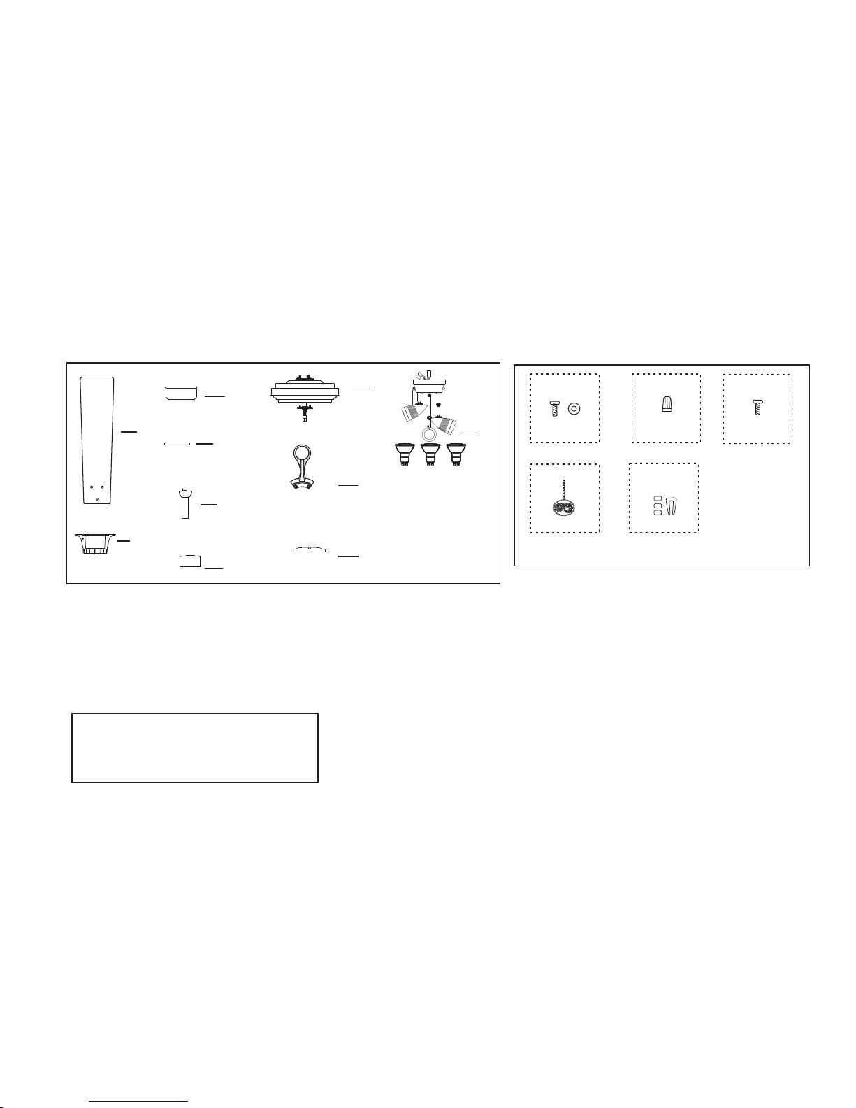
Unpacking Your Fan
Unpack your fan and check the contents. You should have the following items:
WARNING
DO NOT INSTALL OR USE FAN IF ANY
PART IS DAMAGED OR MISSING.
CALL TOLL FREE .1-877-262-7511
2
3
1
2
6
4
8
5
9
7
9. Switch c over
10. Light k it with bul bs (1)
(1)
1. Fan
2. Hanger b racket( 1)
3. Canopy ( 1)
4. Canopy c over(1)
5. Downro d assembl y (1)
6. Coupli ng cover( 1)
7. Fan moto r assembl y( 1 )
8. Blade ho lders (5 )
blades (5 )
11. Loose parts bag containing:
a . Blade attachment hardware (16 screws
and pap er wash ers)
b. Mounting ha rdwar e (3 plas tic wir e
conne ctors )
c. Set of blade br acket h ardwa re (1 scr ew)
d. Pull ch ain fob ( 2)
e. Balancing kit (1)
11
b
a
c
e
d
10
 Loading...