

HAMPTON BAY HI200 Owners And Installation Manual

Owner's & Installation Manual
HI200
Wood Cast
Insert
Tested by:
Installer: Please complete the details on the back cover
and leave this manual with the homeowner.
Homeowner: Please keep these instructions for future reference.
919-555
FPI FIREPLACE PRODUCTS INTERNATIONAL LTD. 6988 Venture St., Delta, BC Canada, V4G 1H4
www.hampton-re.com
05.15.15

2
|
Thank-you for purchasing a HAMPTON PRODUCT.
The pride of workmanship that goes into each of our products will give you years of trouble-free enjoyment. Should you have any questions about your product
that are not covered in this manual, please contact the HAMPTON DEALER in your area. Keep those HAMPTON FIRES burning.
“This wood heater has a manufacturer set minimum low burn rate that must not be altered. It is against federal regulations to alter this setting or otherwise
operate this wood heater in a manner inconsistent with operating instructions in this manual." Failure to follow the manual details can lead to smoke and CO
emissions spilling into the home. It is recommended to have monitors in areas that are expected to generate CO such as heater fuelling areas.
“U.S. ENVIRONMENTAL PROTECTION AGENCY Certied to comply with 2015 particulate emission standards using crib wood". Not approved for sale after
May 15, 2020.”
Model Regency HI200 – 3.0 g /hr.
SAFETY NOTE: If this woodstove is not properly installed, a house re may result. For your safety, follow the installation instructions, contact local building,
re ofcials, or authority having jurisdiction about restrictions and installation inspection requirements in your area.
The following statements are required by the Environmental Protection Agency:
“This manual describes the installation and operation of the Regency HI200 wood heater. This heater meets the 2015 U.S. Environmental Protection Agency’s
crib wood emission limits for wood heaters. Under specic test conditions this heater has been shown to deliver heat at rates ranging from 10,600 BTU/hr. to
34,700 BTU/hr” This unit has been tested using 5G series and generates the best efciency when operated using well-seasoned wood and installed in the
main living areas where the majority of the chimney is within the building envelope and fully lined.”
"It is against federal regulation to operate this wood heater in a manner inconsistent with operating instructions in this manual, or if any parts are removed. “
It is against federal regulation to operate this wood heater in a manner inconsistent with operating instructions in this manual.
CAUTION: BURN UNTREATED WOOD ONLY. OTHER MATERIALS SUCH AS WOOD PRESERVATIVES, METAL FOILS, COAL,
PLASTIC, GARBAGE, SULPHUR OR OIL MAY DAMAGE THE HEATER
"This heater is designed to burn natural wood only. Higher efciencies and lower emissions generally result when burning air dried seasoned hardwoods, as
compared to softwoods or to green or freshly cut hardwoods."
DO NOT BURN:
• Treated wood
• Coal
• Garbage
• Cardboard
• Solvents
• Colored Paper
• Trash
Burning these materials may result in release of toxic fumes or render the heater ineffective and cause smoke.
The authority having jurisdiction (such as Municipal Building Department, Fire Department, Fire Prevention Bureau, etc.) should be consulted before installa-
tion to determine the need to obtain a permit.
This unit must be connected to either a listed factory built chimney suitable for use with solid fuels and conforming to ULC629 in Canada or UL-103HT in the
United States of America or code approved masonry chimney with ue liner.
HI200 is tested and certied to ULC-S628 and UL1482
• Lawn clippings or yard waste • Manure or animal remains
• Materials containing rubber including tires • Saltwater driftwood or other previously salt water
• Materials containing plastic • Unseasoned wood
• Waste petroleum products , paints or paint thinners or asphalt products • Paper products, cardboard, plywood or particle
• Materials containing asbestos
• Construction or demolition debris
• Railroad ties
saturated materials
board. The prohibition against burning these
materials does not prohibit the use of fire starters
made from paper, cardboard, saw dust, wax and
similar substances for the purpose of starting a
fire in a wood heater
SAVE THESE INSTRUCTIONS
2 | HI200 Hampton Wood Cast Insert

table of contents
|
3
SAFETY LABEL
Copy of Safety Label .....................................................4
DIMENSIONS
Unit Dimensions with .....................................................5
Standard Flue Adaptor...................................................5
INSTALLATION
Unit Dimensions with .....................................................6
Offset Flue Adaptor ........................................................6
Before Installing Your Insert...........................................7
Chimney Specications .................................................7
Fireplace Specications.................................................7
Masonry And Factory Built Fireplace Clearances .........8
How To Determine If Alternate .......................................8
Floor Protection Materials Are Acceptable.....................8
Installing Your Insert ...................................................... 9
Installation Into a Factory Built Fireplace..................... 11
Installation Into a Masonry Fireplace ........................... 11
Stainless steel smoke deector adjustment / replace-
ment.............................................................................12
Fan & Cast Faceplate Installation................................13
Brick Flue Bafe & Secondary Air Tube Installation ....15
Firebrick Assembly ......................................................15
Draft Control ................................................................15
OPERATING INSTRUCTIONS
Seasoned Wood ..........................................................16
First Fire ......................................................................17
Fan Operation..............................................................17
Ash Disposal................................................................18
Some Safety Guidelines ..............................................18
Creosote ......................................................................18
MAINTENANCE
Door Gasket ................................................................19
Glass Cleaning ............................................................19
Door Removal..............................................................19
Glass Replacement .....................................................19
Handle Replacement ...................................................20
Latch Adjustment .........................................................20
PARTS LIST
Main Assembly ............................................................23
Firebrick .......................................................................24
Cast Faceplate ............................................................24
WARRANTY
Warranty ......................................................................27
HI200 Hampton Wood Cast Insert | 3

4
Part #: 918-740b
Colour: Black on grey, except for selected items which are printed red.
Size: 15.75" W x 2" H (File at 100%)
Mar. 13/08: Approved by ITS.
Mar. 2/10: updated manufacture dates/ITS logo
Apr. 4/11: updated manufacture dates/add 5.5" liner
Oct. 3/13: Rev. A updated manufacture dates
Nov. 25/14: Rev. B - Updated ETL logo
LISTED FACTORY BUILT FIREPLACE INSERT
CERTIFIED FOR USE IN CANADA AND U.S.A.
MODEL: HI200
TESTED TO:
ULC S628-M93 / UL 1482-1998 / ULC S627-00 / UL 737-2000 REPORT NO. 632-3198 (SEPT.1993)
DO NOT REMOVE THIS LABEL
339
COMPONENTS REQUIRED FOR INSTALLATION: 5.5" (140mm) or 6" (152MM) STAINLESS STEEL LINER. STANDARD ADAPTOR (171-932) OR
OFFSET ADAPTOR (171-936), FAN (210-911 or 210-915), ELECTRICAL RATING: VOLTS 115, 60 HZ, 0.6 AMPS
OPTIONAL COMPONENT: SCREEN DOOR (846-101)
DO NOT REMOVE BRICKS OR MORTAR IN MASONRY FIREPLACE. FOR USE WITH SOLID WOOD FUEL ONLY. DO NOT USE GRATE OR ELEVATE
FIRE. BUILD WOOD FIRE DIRECTLY ON HEARTH. OPERATE WITH FEED DOOR CLOSED, OPEN TO FEED FIRE ONLY. REPLACE GLASS ONLY
WITH CERAMIC GLASS (5MM). INSPECT AND CLEAN CHIMNEY FREQUENTLY. UNDER CERTAIN CONDITIONS OF USE CREOSOTE BUILDUP
MAY OCCUR RAPIDLY. DO NOT OVERFIRE, IF INSERT GLOWS YOU ARE OVER-FIRING.
MINIMUM CLEARANCES TO COMBUSTIBLE MATERIALS (MEASURED FROM INSERT BODY)
INSTALL ONLY ON A NON-COMBUSTIBLE HEARTH RAISED (F) 1.5IN / 38MM
ABOVE AN ADJACENT COMBUSTIBLE FLOOR. COMBUSTIBLE FLOOR MUST
BE PROTECTED BY NON-COMBUSTIBLE MATERIAL EXTENDING
(E) 16 IN / 405MM (US), 18 IN / 457MM (CAN) TO FRONT AND (G) 8 IN / 205MM
TO SIDES FROM FUEL DOOR.
918-740b
MANUFACTURED BY:
FPI FIREPLACE PRODUCTS INTERNATIONAL LTD.
6988 VENTURE ST.
DELTA, BC V4G 1H4
HOT WHILE IN OPERATION
DO NOT TOUCH. KEEP CHILDREN,
CLOTHING AND FURNITURE AWAY.
CONTACT MAY CAUSE SKIN BURNS.
READ ABOVE INSTRUCTIONS.
CAUTION
ADJACENT SIDEWALL A) 15in / 380mm
MANTLE B) 20in / 510mm
TOP FACING C 14in / 355 mm
SIDE FACING D) 7.375in / 185mm
INSTALL AND USE ONLY IN ACCORDANCE WITH THE MANUFACTURER'S INSTALLATION AND OPERATING INSTRUCTIONS. INSTALL AND USE ONLY
IN MASONRY FIREPLACE OR FACTORY BUILT FIREPLACE.
CONTACT LOCAL BUILDING OR FIRE OFFICIALS ABOUT RESTRICTIONS AND INSTALLATION INSPECTION IN YOUR AREA.
JAN FEB MAR APR MAY JUN JUL AUG SEPT OCT NOV DEC
2015 2016 2017
(Duplicate
Serial #)
MADE IN CANADA
339
DATE OF
MANUFACTURE
|
safety decal
This is a copy of the label that accompanies each
HI200 Wood Insert. We have printed a copy of
the contents here for your review.
NOTE: Hampton units are constantly being
improved. Check the label on the unit and if
there is a difference, the label on the unit is
the correct one.
4 | HI200 Hampton Wood Cast Insert
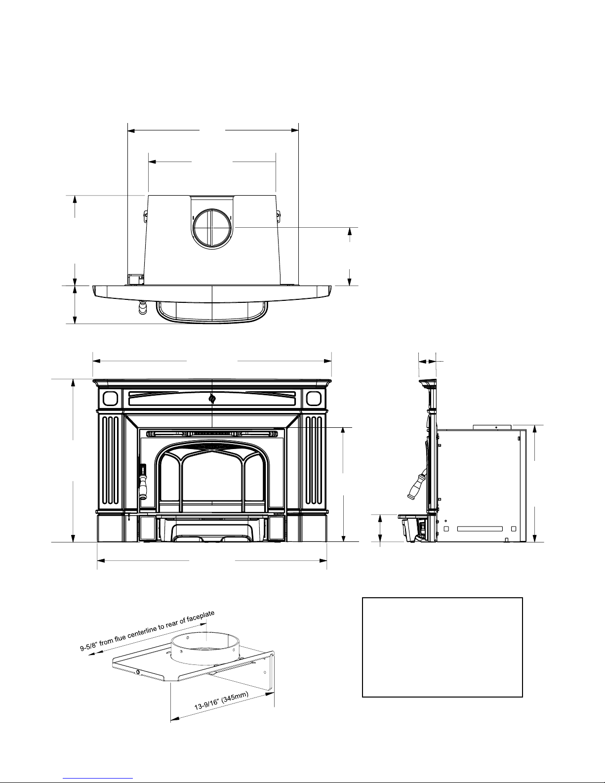
UNIT DIMENSIONS WITH
STANDARD FLUE ADAPTOR
25
21-1/4
dimensions
|
5
15-1/16
6-3/8
39-13/16
27-1/4
9-5/8
2-7/8
19
19-9/16
to top of Door
38-5/16
6" (152mm) Diameter
STANDARD FLUE ADAPTOR (171-932)
HI200 Hampton Wood Cast Insert | 5
NOTE:
Before assembling your Insert,
use these dimensions to ensure appropriate clearances
will be met (refer to Masonry
and Factory Built Fireplace
Clearances section).
6
25
faceplate
|
dimensions
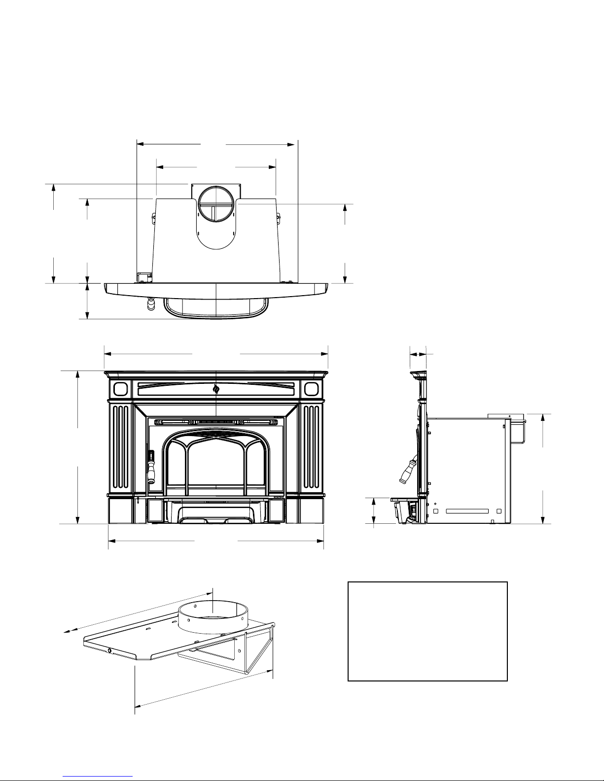
UNIT DIMENSIONS WITH
OFFSET FLUE ADAPTOR
21-1/4
17-11/16
15-1/16
6-3/8
39-13/16
27-1/4
38-5/16
14-1/8
2-7/8
19-9/16
6" (152mm) Diameter
OFFSET FLUE ADAPTOR (171-936)
14-1/8 from flue centerline to rear of
16-15/16 (430mm)
6 | HI200 Hampton Wood Cast Insert
NOTE:
Before assembling your Insert,
use these dimensions to ensure appropriate clearances
will be met (refer to Masonry
and Factory Built Fireplace
Clearances section).

installation
|
7
Hampton Inserts are constructed with the highest quality materials and assembled under strict
quality control procedures that ensure years of
trouble free and reliable performance.
It is important that you read this manual thoroughly and fully understand the installation and
operating procedures. Failure to follow instructions may result in property damage, bodily injury
or even death. The more you understand the way
your Hampton Insert operates, the more enjoyment you will experience from knowing that your
unit is operating at peak performance.
BEFORE INSTALLING
YOUR INSERT
1) Read all instructions before installing and
using your replace insert. Install and use
only in accordance with manufacturer’s
installation and operating instructions.
2) Check your local building codes - Building Inspection Department. You may
require a permit before installing your
insert. Be aware that local codes and
regulations may override some items in
the manual.
WARNING: Careless installation is the
major cause of safety hazard. Check all
local building and safety codes before
installation of unit.
3) Notify your home insurance company that
you plan to install a replace insert.
4) Your replace insert is heavy and requires
two or more people to move it safely. The
insert and surrounding structure can be
badly damaged by mishandling.
5) If your existing replace damper control
will become inaccessible once you have
installed your Hampton Insert, you should
either remove or secure it in the open position.
6) Inspect your replace and chimney prior
to installing your insert to determine that it
is free from cracks, loose mortar or other
signs of damage. If repairs are required,
they should be completed before installing
your insert. Do not remove bricks or mortar
from your masonry replace.
7) Do not connect the insert to a chimney
ue servicing another appliance or an air
distribution duct.
CHIMNEY
SPECIFICATIONS
Before installing, check and clean your chimney
system thoroughly. If in doubt about its condi-
tion, seek professional advice. Your Hampton
Insert is designed for installation into a masonry
replace that is constructed in accordance with
the requirements of "The Standard for Chimneys,
Fireplaces, Vents, and Solid Fuel Burning Appliance", N.F.P.A. 211, the National Building
Code of Canada, or the applicable local code
requirements.
The appliance, when installed, must be electrically grounded in accordance with local codes or,
in the absence of local codes, with the National
Electrical Code, ANSI/NFPA 70, or the Canadian
Electrical code, CSA C22.1.
Hampton Inserts are designed to use either a
5.5" (140mm) or 6" (152mm) ue.
This insert must be connected to a code-approved masonry chimney or listed factory-built
replace chimney with a direct ue connector
into the rst chimney liner section. The chimney
size should not be less than or more than three
times greater than the cross-sectional area of
the ue collar.
Requirements for Installing
Solid-fuel Inserts in Factory-built
Fireplaces.
1) The insert must be tested and meet the
requirements of UL 1482 (U.S.) and or ULC
S628 (Canada) when tested in a masonry
replace built per ULC S628.
2) The factory-built replace must be listed per
UL 127 or ULC S610.
3) Clearances obtained from the masonry re-
place tests are also relevant for installation
in factory-built replaces.
4) Installation must include a full height listed
chimney liner type HT requirements (2100
degree F.) per UL 1777 (U.S.) or ULC
S635 (Canada). The liner must be securely
attached to the insert ue collar and the
chimney top.
5) Means must be provided to prevent room
air passage to the chimney cavity of the
replace. This may be accomplished by
sealing the damper area around the chimney
liner, or sealing the replace front.
6) Alteration of the replace in any manner is
not permitted with the following exceptions;
a. external trim pieces which do not affect
the operation of the replace may be
removed providing they can be stored on
or within the replace for re-assembly if
the insert is removed.
b. the chimney damper may be removed to
install the chimney liner.
7) Circulating air chambers (i.e. in a steel re-
place liner or metal heat circulator) shall not
be blocked.
8) Means must be provided for removal of the
insert to clean the chimney ue.
9) Inserts that project in front of the replace
must be supplied with appropriate supporting
means.
10) Installer must mechanically attach the sup-
plied label to the inside of the rebox of the
replace into which the insert is installed.
"WARNING: This replace has been converted
for use with a wood insert only and cannot be
used for burning wood or solid fuels unless
all original parts have been replaced, and the
replace re-approved by the authority having
jurisdiction."
FIREPLACE
SPECIFICATIONS
Your replace opening requires the following
minimum sizes:
Height: 19-5/8" (499mm)
Width: 25" (635mm)
Depth:
(w/ standard ue adaptor) 15-1/16" (383mm)
(w/ offset ue adaptor) 17-11/16" (449mm)
Faceplate Dimensions:
Height 27-1/4" (692mm)
Width 38-5/16" (973mm)
Emissions from burning wood or gas could
contain chemicals known to the State of California to cause cancer, birth defects or other
reproductive harm.
HI200 Hampton Wood Cast Insert | 7

8
|
installation
MASONRY AND FACTORY BUILT FIREPLACE CLEARANCES
The minimum required clearances to combustible materials when installed into a masonry or factory built replace are listed below.
Adjacent
Side Wall
(to side)
A B C D E F G H
15" (381mm) 20"(508mm) 14" (356mm) 7-3/8" (187mm) 16" (406mm)
Side and Top facing is a maximum of 1.5" thick.
Floor protection must non-combustible, insulative
material with an R value of 1.1 or greater.
* If the hearth extension is ush with the oor (F)
it must extend 19.5" in front of the body face
(E).
Note: Hearth Extension Width (G) is meas-
ured from edge of fuel door to side of
hearth.
Mantel**
(to Top)
Top
Facing
(to Side of Door)
Side
Facing
(to Side of Door)
Minimum
Hearth
Extension
[USA]
18" (457mm)
[CAN)
Minimum
Hearth
Thickness*
1-1/2" (38mm) 6" (152mm) [USA]
B
C
Minimum
Hearth Side
Extension
8" (203mm) [CAN]
From Top of
Door
19" (483mm)
*** Mantel depth, maximum of 10" (254mm)
** A non-combustible mantel may be installed
at a lower height if the framing is made of
metal studs covered with a non-combustible
board.
Thermal oor protection is not required if the unit is
raised 3.5" minimum (measured from the bottom of
the stove). However, standard ember oor protection
is required. It will need to be a non-combustible mate-
rial that covers 16" (406 mm) in the US and 18" (450
mm) in Canada to the front of the unit and 8" (200
mm) to the sides.
If the unit is not raised, thermal oor protection required
is 18" (450 mm) in the US and Canada.
Floor Protection
Please check to ensure that your oor protection and hearth will meet the standards for clearance to combustibles. Your hearth extension must be made from a non-combustible material.
A
H
F
Clearance diagram for installations
HOW TO DETERMINE IF ALTERNATE
FLOOR PROTECTION MATERIALS ARE ACCEPTABLE
The specied oor protector should be 3/8"
(18mm) thick material with a K - factor of
0.84.
The proposed alternative is 4" (100mm) brick
with a C-factor of 1.25 over 1/8" (3mm) mineral
board with a K-factor of 0.29.
Step (a):
Use formula above to convert specication
to R-value.
R = 1/k x T = 1/0.84 x .75 = 0.893.
Step (b):
Calculate R of proposed system.
4" brick of C = 1.25, therefore
Rbrick = 1/C = 1/1.25 = 0.80
1/8" mineral board of k = 0.29, therefore
Rmin.bd. = 1/0.29 x 0.125 = 0.431
Total R = Rbrick + Rmineral board =
0.8 + 0.431 = 1.231.
Step (c):
Compare proposed system R of 1.231 to
specied R of 0.893. Since proposed system
R is greater than required, the system is
acceptable.
D
G
DEFINITIONS
Thermal Conductance:
C = Btu = W
(hr)(ft
Thermal Conductivity:
k = (Btu)(inch) = W = Btu
(hr)(ft
R = (ft2)(hr)(oF) = (m2)(K)
Btu W
3)(o
Thermal Resistance:
2 )(o
F) (m2))(K)
F) (m)(K) (hr)(ft)(oF)
E
8 | HI200 Hampton Wood Cast Insert

INSTALLING YOUR INSERT
installation
|
9
STOP! PLEASE READ CAREFULLY.
CAST COMPONENTS ARE VERY FRAGILE.
USE EXTREME CARE WHEN HANDLING.
Your insert is very heavy and will require two or three people to
move it into position.
1) Remove the Door to make the insert easier to handle.
To remove the Door, open fully and release the push pin at the top
of the door and lift out from the bottom.
Push Pin
3) Lift the unit up onto the Hearth and slide into the replace opening.
Be sure to leave the unit out at least 3 to 4 inches in order to make
the necessary ue connections and to install the fan and faceplate.
Be sure to protect your hearth extension during the installation,
ie. with a heavy blanket.
NOTE: You will be required to purchase either the standard or offset
6" diameter (152mm) ue adaptor that is best suited for the specic
installation.
List of Tools needed;
- Pull Rod (included with insert)
- 1/2” socket / ratchet
- 3/8 open face wrench
4) Install ex liner into existing chimney as per liner manufacturer’s
specications. See diagram 1.
5) Install the required ue adaptor onto the end of the ex liner. Secure
the adaptor using 3 screws - 1 on the front, left and right side as
shown in diagram 2.
Alignment of the ue adaptor can be critical during the install, it is
recommended that the ex liner be left as compressed as possible.
Before inserting the unit the adaptor should hang, when level, slightly
above the required height.
2) NOTE: For Masonry installation make sure that the rebox is level
with the hearth using non-combustible materials and no more than
1/2 to 1 inch of the leveling bolt.
HI200 Hampton Wood Cast Insert | 9
Diagram 1
Diagram 2
Secure adaptor using 3 screws - 1 in the front
and 1 each on the left and right side.
Flex Liner
Flue Adaptor
 Loading...