

Page 1
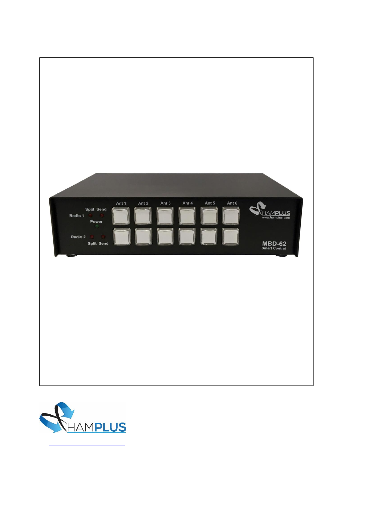
MBD-62 AUTOMATIC CONTROLLER
http://www.hamplus.com
Instruction Manual
V. 1.0
Page 2

MBD-62
Instruction Manual
___________________________________________________________________________________
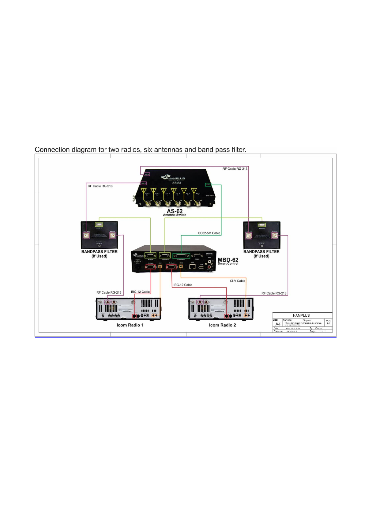
The MBD-62 is an automatic controller for six-antenna two radios switch. It allows the
simultaneous operation of the two radios in different antennas. It has been specially designed
for use with the AS-62 antenna switch. It also has two special outputs called Aux Out 1 and
Aux Out 2, to automatically control external equipment such as Band Pass Filter. These
outputs can also provide Frequency-Driven or Band-driven General Purpose Output (GPO)
commands for a variety of uses, such as shortened antenna tuning box with high Q coils or to
de-tuning antennas or any other use.
The antenna exchange can be manual through its Push Buttons, or automatic through the
exchange of band on the radio connected to it.
In automatic antenna switching, the MBD-62 will always trigger the last antenna used in that
band. Any of the six antennas can be selected for any selected band on the radio. Just as the
same antenna can be chosen for all selected bands on the radio. The procedure for setting up
the antenna for each band is very simple. You only have to put the radio in a band and then
press on the MBD-62 the antenna Push Button that will be used in this band. Repeat this
operation for each band and so all bands will have the antennas memorized.
Remote Operation
Another way to operate the MBD-62 is through remote control. For this, Hamplus offers
the ROS-62, a software for PC. With an RS-232 port and a LAN port the MBD-62 can be
connected to a local network or the Internet for remote operation.
Special Commands
1- Antenna Release
For radios connected with the appropriate control cable, the radio must only be switched
off. For radios that do not have CAT, press Ant.1 Button and Ant.6 Button at the same
time. Top Ant.1 Button for Radio 1 or Lower Ant.1 Button for Radio 2.
2- Antenna Split Mode
To activate Antenna Split Mode, put the radio on the transmit antenna, and then press the
PTT. With the PTT pressed down, press the Push Button corresponding to the antenna
that you want to receive for two seconds. Then release the PTT and watch the MBD-62
switch to the antenna you chose to receive. Each time you press the PTT, the MBD-62 will
switch to the transmitting antenna. In Antenna Split Mode you can select any free
antenna for reception.
To deactivate the Antenna Split Mode, press the transmit antenna Push Button or change
the radio band.
3- Updating Firmware
a- Step 1 Download the new Firmware version on the Hamplus site on a USB memory stick.
b- Step 2 Insert the USB memory stick into the USB port on the MBD-62
c- Step 3 Press and hold the Ant.4, Ant.5 and Ant.6 Buttons sequentially on the top line. All
Buttons will light indicating the start of the update. Then release the Buttons. At the end of
the update all Buttons will flash a few times. The blinking indicates that the update was
successful.
Page 3

4- Connecting the MBD-62 to your radio
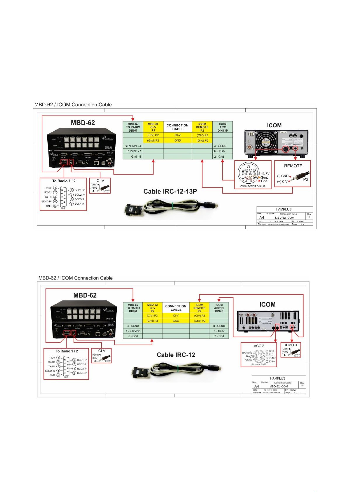
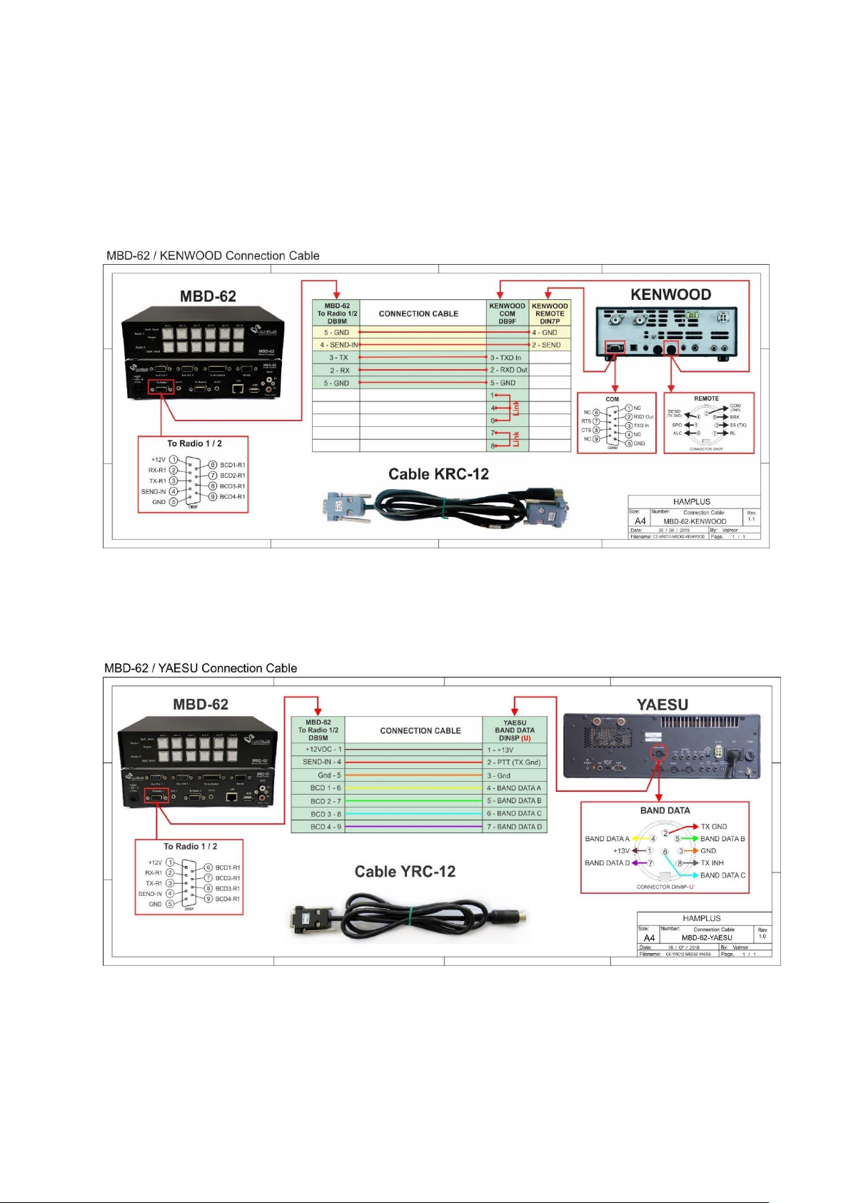
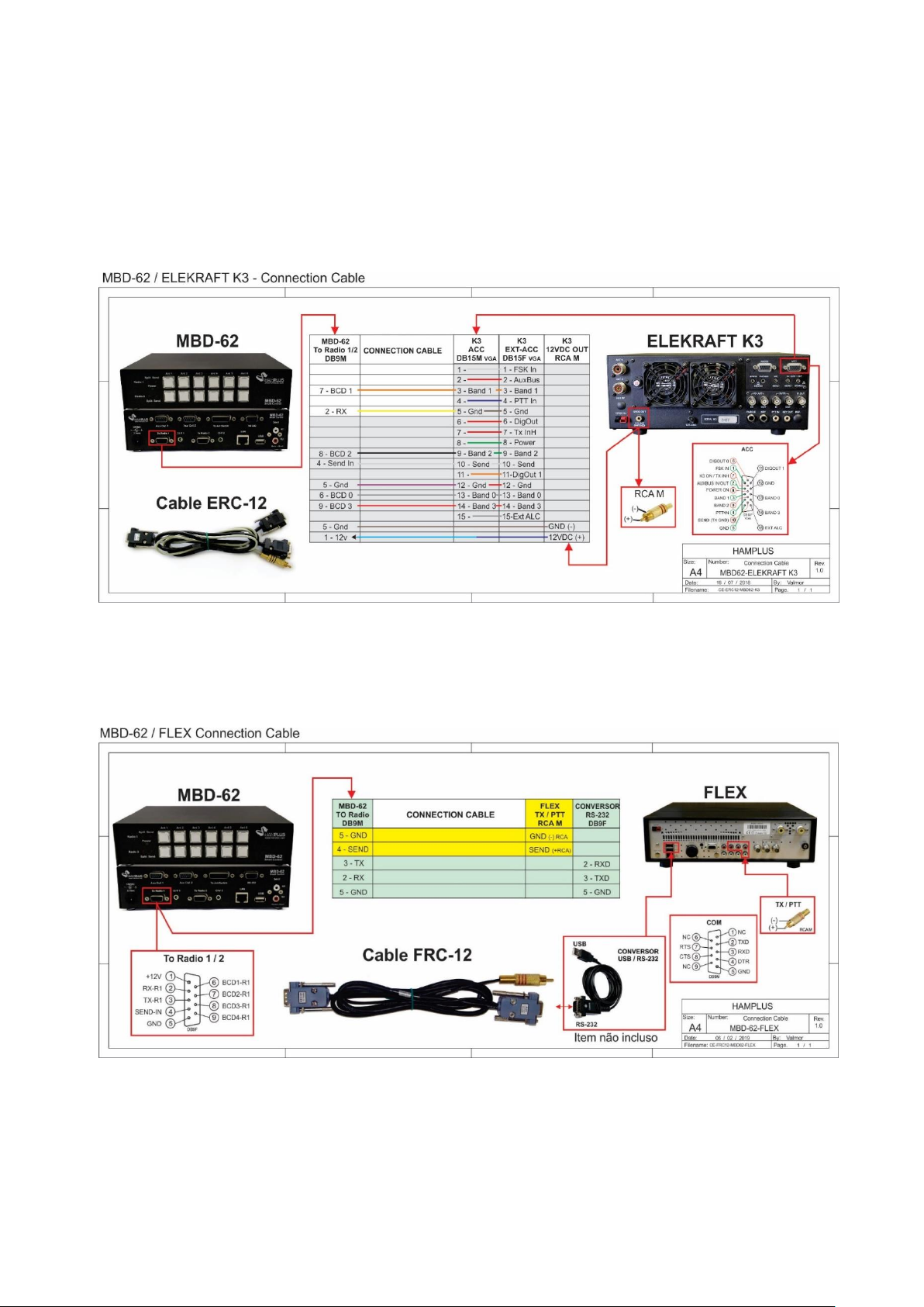
a- Step 1- Use the appropriate cable to connect the MBD-62 to your radio.
b- Step 2- For radios that use the connection via CAT it is necessary to choose the baud rate.
The Baud Rate should be the same on Radio and MBD-62.
A- Choosing MBD-62 Baud Rate
To help with the setup of the MBD-62 you should also use the Quick Reference Map
1- Step 1 -Press the Ant.1 Button corresponding to the desired Radio for more than two
seconds to enter the Set Up mode. Top Ant.1 Button for Radio 1 or Lower Ant.1 Button for
Radio 2.
2- Step 2 -Press the upper Ant.1 Button to choose the Baud Rate for communication with the
Radio or the upper Ant.3 Button to choose the Baud Rate of the RS-232 port
3- Step 3 -Press one of the upper Button Ant.1 to Ant.5 to choose the desired speed, 9600,
19200, 38400, 57600 or 115200.
At this time MBD-62 is already with the chosen Baud Rate.
4- Step 4 -To save and exit Setup mode, press the lower Ant.6 Button that is flashing.
B- Selecting the function for AUX OUT 1 or 2
The MBD-62 has two outputs named Aux Out 1 (DB-9M) and Aux Out 2 (DB-9M) which
correspond to the functions that will be performed by Radios 1 and 2 respectively. To
choose the functions for Radio 1, enter the Set Up mode by pressing the upper Ant.1
Button for a little more than 2 seconds or the lower Ant.1 Button for Radio 2 for a little
more than 2 seconds.
There are five options for each Aux Out:
1- DX Engineering DXE-419 Band Pass Filter
2- Array Solutions AS-419 Band Pass Filter
3- Dunestar 600 Band Pass Filter
4- GPO per antenna
5- GPO on all six antennas
C- Choosing the Band Pass Filter
ATTENTION: Only connect the control cable between the Band Pass Filter and the Aux Out
connector of the MBD-62 after completing the setup.
- To help with the setup of the MBD-62 you should also use the Quick Reference Map
- The Band Pass Filter setting is individual for each Radio. Therefore each Radio
should receive the proper configuration of the Band Pass Filter that it will use.
1- Step 1- Press the Ant.1 Button for more than two seconds to enter Setup mode.
Top Ant.1 Button for Radio 1 or Lower Ant.1 Button for Radio 2.
2- Step 2- Press the Ant.2 Button to enable the selection of one of the five available
functions.
3- Step 3-The choice of Band Pass Filter;
a- Press the Ant.1 Button to select DX Engineering DXE-419 Band Pass Filter
b- Press the Ant.2 Button to select Array Solution AS-419 Band Pass Filter
c- Press the Ant.3 Button to select Dunestar 600 Band Pass Filter
4- Step 4- To save and exit Setup mode, press the lower Ant.6 Button that is flashing.
These filters are connected to the MBD-62 with pin-to-pin cables. Other Band Pass Filter can
be used but it is necessary to verify the correct connection of all the pins and if the drive is
with + 12V or GND.
AS-419 is active high (+12V) ,DXE-419 is active low (GND) and Dunestar 600 is active high
(+12V)
Page 4

GPO commands
GPOs are typically used to tune shortened antennas with high Q coils and also to tune
out TX/RX antennas that are influencing reception antennas.
To help with the setup of the MBD-62 you should also use the Quick Reference Map
- The configuration of the GPO by Antenna is made for the antenna in the Band
chosen in the Radio. Therefore any of the two Radios that are in this Band and in this
antenna will trigger the GPOs.
To choose GPO per Antenna (General Purpose Output associated with an antenna position)
1- Step 1- Press the Ant1 button for two seconds to enter Set Up mode
2- Step 2- Press the Ant 2 button to choose one of the five available functions in Aux Out.
3- Step 3- Press the Ant4 button to choose GPO by Ant, (GPO per antenna)
4- Step 4- Press the button (1 to 6) corresponding to the antenna you want to associate with the
GPOs
5- Step 5- Press the Ant 1 button for Active High (+ 12v) or the Ant2 button for Active Low (GND)
6- Step 6- To mark the trigger points of the GPOs:
a- GPO per Band -
- Step 1 - Put the radio on a frequency in the band that you want to trigger the GPO. This
is done, then press the Ant.3 button for the always-on GPO in the entire selected band, or
the Ant.4 Button for GPO triggered on the entire Band selected but only when it is in
reception.
- Step 2 - Choose which GPO will be triggered. Buttons Ant 1 through Ant 6 correspond to
GPO1 through GPO6. The GPO 7 is triggered by the lower Ant.1 button (Button Ant.1 of
radio 2). Press one of them to mark the GPO.
-To save and exit Setup mode, press the blinking lower Ant 6 button.
b- GPO by Frequency –
You can use as many GPOs you want within the same band or use some in one band and
the rest in other bands.
- Mark the first GPO. Set the radio to the frequency at which you want to trigger
the first GPO. Press the Ant1 button to mark the GPO1. This GPO will be triggered
from the selected frequency to the end of the Band or until the next GPO,
whichever comes first.
- Mark the second GPO. On the radio dial increase the frequency to the next point
at which you want to trigger the second GPO. Then press the Ant.2 button to mark
the GPO2 point.
- To mark more GPOs. Repeat the previous procedure
To save and exit Setup mode, press the lower button Ant.6 that is blinking.
c- GPO at the midpoint between two frequencies.
GPO activation at the midpoint between two frequencies makes it easier to tune
the tuned box of shortened antennas using high Q coils. To mark the input
frequency and the output frequency simply find the lowest SWR point for each
from them.
-Mark the first GPO. This GPO will be triggered at the midpoint between the two
frequencies chosen.
Step 1- To mark the first GPO start at the beginning of the band and choose the frequency
with the lowest SWR in the radio. Then press the Ant1 button to mark the entry point for
the GPO1. The Ant1 button will blink.
Page 5

Step 2- Increase the frequency on the radio dial until you find the next lowest SWR point.
Press the Ant.1 button again. Then the Ant.1 button stops blinking, and this indicates that
the GPO1 is marked and will be triggered at the midpoint between the two frequencies.
-To mark the second GPO in the same Band. Keeping the radio still at the lowest SWR
frequency press the Ant.2 button to mark the GPO2 entry point. The Ant.2 button has
started blinking. On the radio dial increase the frequency until you find the next lowest
SWR point. Press the blinking Ant.2 button again to mark the exit point of the GPO2. The
Ant.2 button stops blinking indicating that the GPO2 is checked.
- To mark more GPOs Repeat the procedure used to mark the previous GPO.
-To save and exit Setup mode, press the blinking lower Ant 6 button.
---------------------x--------------------
EXAMPLE:
Let's go to the procedure to set the Baud Rate on the MBD-62
First step:
To enter the config mode for Radio 1, push the upper ANT 1 button until the lower ANT 6
button blinks (2 to 4 sec).
To enter the config mode for Radio 2, push the lower ANT 1 button until the lower ANT 6
button blinks (2 to 4 sec).
Second step:
To set the Baud Rate to the Radio, push the upper ANT1 button.
Third step:
Now choose the Baud Rate
Upper Push Button ANT1 to 9600
Upper Push Button ANT2 to 19200
Upper Push Button ANT3 to 38400
Upper Push Button ANT4 to 57600
Upper Push Button ANT5 to 115200
Fourth step:
To save and exit config mode, push the lower ANT6 button that is still blinking.
After this procedure the MBD-62 will be with the chosen Baud Rate
It is important that the MBD-62 and the radio have the same Baud Rate.
Page 6
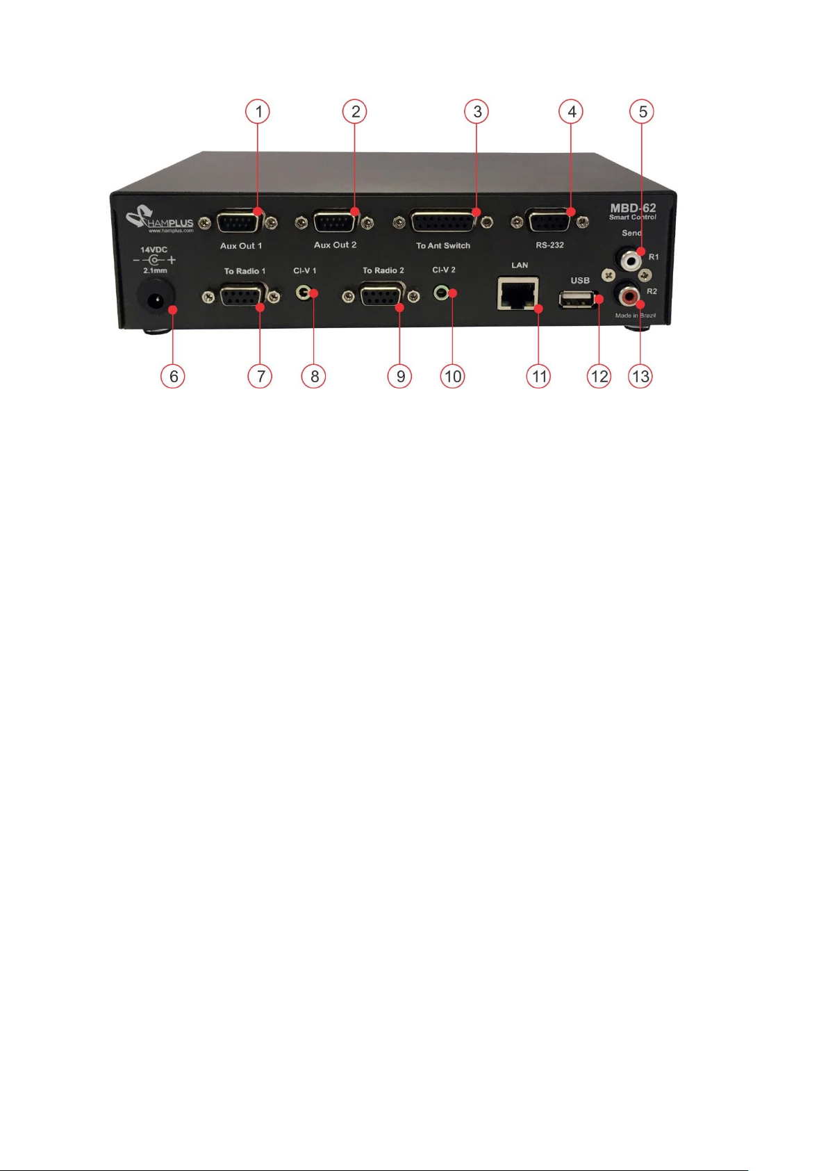
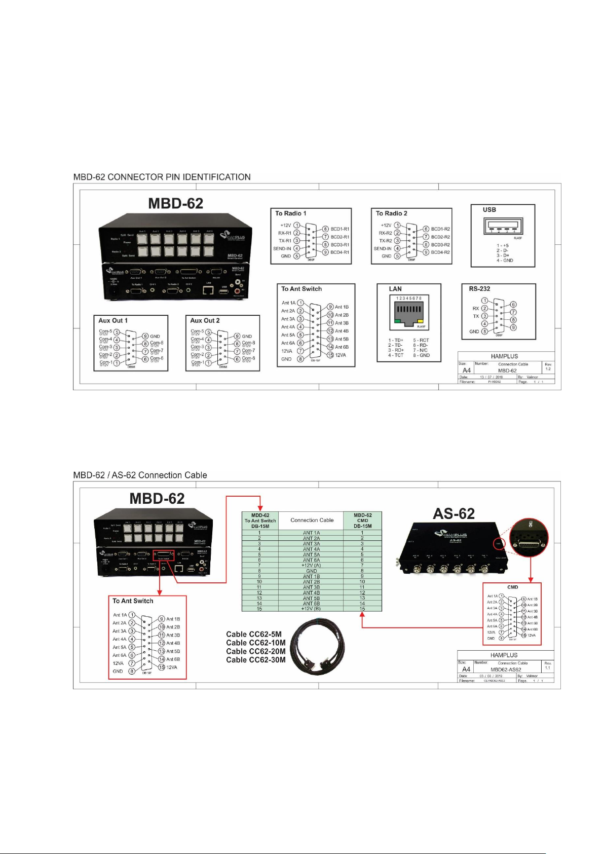
1- Aux Out 1 DB-9M Auxiliary Output of Radio 1
2- Aux Out 2 DB-9M Auxiliary Output of Radio 2
3- To Ant Switch DB-15F Control output for Antenna Switch AS-62
4- RS-232 DB-9F Standard connection RS-232
5- Send Out R1 RCA Send Out connector for control of Linear Amp of Radio 1
6- 14VDC External power input 14 VDC
7- To Radio 1 DB-9F for connection to Radio 1
8- CI-V1 P2 connector for CI-V of Radio Icom 1
9- To Radio 2 DB-9F for connection to Radio 2
10- CI-V2 P2 connector for CI-V of Radio Icom 2
11- LAN RJ45 LAN for network connection
12- USB USB connector for Firmwere upgrade
13- Send Out R2 RCA Send Out connector for control of Linear Amp of Radio 2
Page 7
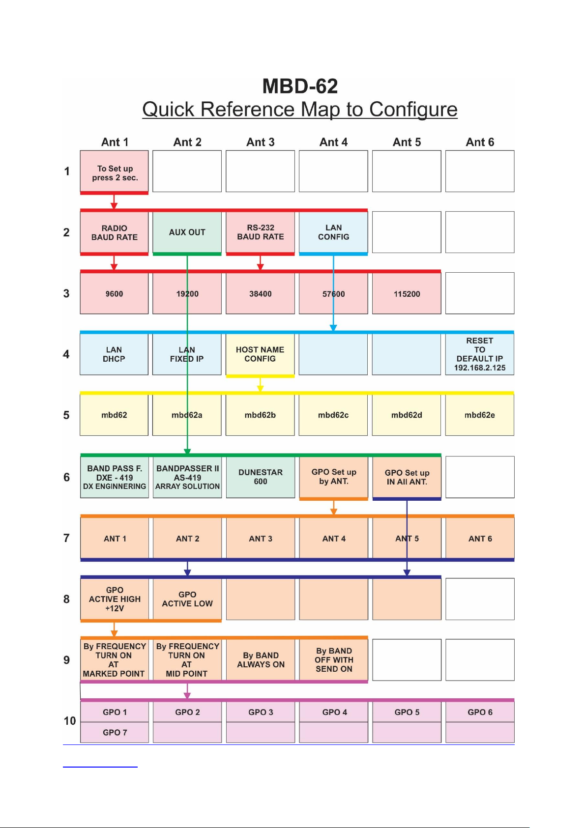
Firmware V.1.2
Page 8
Page 9
Page 10
Page 11
Page 12
Page 13
Page 14
Page 15
 Loading...