

Page 1
Download your local language
DE EN FR
DA
NL
LV SL
http://fg.am/ba-manuals
ES ETCZ
PL SVROIT
PT
FI
RU
User manual
(Translation)
HU
Bandsaw
N2-35
Keep this manual handy and in good condition for continual reference!
Dok.ID: 582033-901_02 • Englisch • 2019-10-22
Page 2
Bandsaw
Note: Year of construction
The machine number of this machine will be printed on the cover sheet of this operating manual.
The final two digits of the machine number show the year of construction of this machine.
e.g. XXX.XX.XXX.19 -> year of manufacture 2019
Attention!: The machine must be inspected immediately upon arrival. If the machine has been damaged during
!
transport, or if any parts are missing, a written record of the problems must be submitted to the forwarding
agent and a damage report compiled. Also be sure to notify your supplier immediately.
N2-35
For the safety of all personnel, it is necessary to study this manual thoroughly before assembly and operation.
This manual must be kept in good condition and should be considered as part of the machine. Furthermore,
the manual must be kept to hand and within the vicinity of the machine so that it is accessible to operators
when using, maintaining or repairing the machine.
Hammer A product of the FELDER GROUP!
© FELDER KG
KR-FELDER-STR.1
A-6060 Hall in Tirol
Tel. +43 (0) 5223 / 45 0 90
Fax: +43 (0) 5223 / 45 0 99
E-mail: info@hammer.at
Internet: www.hammer.at
2
Page 3

Bandsaw
N2-35
Content
1 General .................................................................................................6
2 Safety ...................................................................................................9
Content
1.1 Symbol legend ................................................................................................ 6
1.2 Informationen zur Betriebsanleitung ................................................................... 6
1.3 Liability and warranty ...................................................................................... 7
1.4 Copyright ....................................................................................................... 7
1.5 Warranty notice .............................................................................................. 7
1.6 Spare parts ..................................................................................................... 7
1.7 Disposal ......................................................................................................... 8
2.1 Intended use ................................................................................................... 9
2.2 Manual contents .............................................................................................. 9
2.3 Making changes and modifications to the machine .............................................. 9
2.4 Responsibilities of the operator ........................................................................ 10
2.5 Personnel requirements ................................................................................... 10
2.6 Work safety .................................................................................................. 10
2.7 Personal protective equipment ......................................................................... 11
2.8 Machine hazards .......................................................................................... 11
2.9 Other risks .................................................................................................... 11
3 Declaration of Conformity ....................................................................12
4 Specifications ......................................................................................14
4.1 Dimensions and weight .................................................................................. 14
4.2 Operation and storage conditions ................................................................... 15
4.3 Electrical connection ...................................................................................... 15
4.4 Dust Extractors .............................................................................................. 15
4.5 Noise emission ............................................................................................. 16
5 Setting up the machine ........................................................................18
5.1 Overview ..................................................................................................... 18
5.2 Data plate .................................................................................................... 19
5.3 Automatic braking system ............................................................................... 19
5.4 Safety break switches ..................................................................................... 19
6 Transport, packaging and storage ........................................................20
6.1 Safety instructions .......................................................................................... 20
6.2 Transport inspection ....................................................................................... 20
6.3 Packaging .................................................................................................... 20
6.4 Storage ........................................................................................................ 21
6.5 Transport ...................................................................................................... 21
6.5.1 Transport locking device ...........................................................................................21
6.5.2 Transport with a crane .............................................................................................22
6.5.3 Transport with a rolling carriage ...............................................................................22
3
Page 4

Content
7 Setup and installation ..........................................................................24
7.1 Safety instructions .......................................................................................... 24
7.2 Setup ........................................................................................................... 24
7.2.1 Assemble machine frame (Option) .............................................................................25
7.2.2 Attaching the band saw to the machine frame ............................................................26
7.2.3 Setting up the work table / Angle adjustment .............................................................27
7.2.4 Assembly - Rip fence ................................................................................................28
7.2.5 Positioning and levelling the machine .........................................................................29
7.3 Electrical connection ...................................................................................... 30
8 Operation ...........................................................................................32
8.1 Safety instructions .......................................................................................... 32
8.2 Blade selection and maintenance .................................................................... 33
8.3 Saw blade replacement/tension ...................................................................... 34
8.3.1 Setting - Saw blade track / Lower wheel ....................................................................35
8.4 Tilting the table ............................................................................................. 36
8.5 Adjusting the saw blade guide ........................................................................ 36
8.5.1 Height adjustable protection device ..........................................................................36
8.5.2 Saw blade guide - upper ........................................................................................37
8.5.3 Saw blade guide - down (Option) .............................................................................38
8.6 Switching on the machine / Switching off the machine ....................................... 39
8.7 Authorised working techniques ........................................................................ 39
8.7.1 Longitudinal cut along the marked line .......................................................................39
8.7.2 Cutting round workpieces in the transverse direction ....................................................40
8.7.3 Cutting workpieces on the upright edge .....................................................................40
8.7.4 Longitudinal cut of narrow or thin workpieces with the longitudinal guide fence ..............40
8.7.5 Mitre cuts ...............................................................................................................41
8.7.6 Circular cuts ...........................................................................................................41
8.7.7 Diagonal cross-cut of rectangular workpieces ..............................................................41
Bandsaw
N2-35
9 Service ................................................................................................42
9.1 Safety instructions .......................................................................................... 42
9.2 Tightening/replacing the drive belt .................................................................. 42
9.3 Upper wheel - Replace ................................................................................... 43
9.4 Cleaning and lubrication ................................................................................ 44
9.4.1 Adjustment - saw belt tension ....................................................................................44
9.4.2 Gearbox - Height adjustable protection device ............................................................44
9.4.3 Tiltable table ..........................................................................................................45
9.5 Direction of cut and parallelism ....................................................................... 45
10 Faults ................................................................................................46
10.1 Safety instructions ........................................................................................ 46
10.2 What to do if a fault develops ....................................................................... 46
10.3 What to do after rectifying the fault ............................................................... 46
10.4 Faults, causes and repairs ............................................................................. 47
11 Electrical circuit diagram ................................................................... 48
12 Spare parts ....................................................................................... 50
4
Page 5

Bandsaw
N2-35
Content
5
Page 6
1 General
1.1 Symbol legend
Bandsaw
N2-35
General
Important technical safety instructions in this manual are
marked with symbols.
These instructions for work safety must be followed.
Warning! Risk of injury or death!
This symbol marks instructions that must be followed in order to avoid harm to one‘s health, injuries, permanent impairment or death!
Warning! Danger! Electric current!
This symbol warns of potentially dangerous situations relating to electric current. Not observing the safety instructions increases the risk of serious injury or death. All electrical repairs must be carried out by a
qualified electrician!
Attention! Risk of material damage!
!
This symbol marks instructions which, if not observed, may lead to material damage, functional failures
and/or machine breakdown!
Note:
This symbol marks tips and information which should be observed to ensure efficient and failure-free operation of the machine.
In all these particular cases, special attention must be
paid in order to avoid accidents, injury to persons or
material damage.
1.2 Informationen zur Betriebsanleitung
This manual describes how to operate the machine
properly and safely. Be sure to follow the safety tips and
instructions stated here as well as any local accident
prevention regulations and general safety regulations.
Before beginning any work on the machine, ensure that
the manual, in particular the chapter entitled “Safety”
and the respective safety guidelines, has been read in its
entirety and fully understood. This manual is an integral
part of the machine and must therefore be kept in the
direct vicinity of the machine and be accessible at all
times. If the machine is sold, rented, lent or otherwise
transferred to another party, the manual must accompany
the machine.
6
Page 7

Bandsaw
N2-35
1.3 Liability and warranty
General
The contents and instructions in this manual have been
compiled in consideration of current regulations and
state-of-the-art technology as well as based on our
know-how and experience acquired over many years.
This manual must be read carefully before commencing
any work on or with this machine. The manufacturer
shall not be liable for damage and/or faults resulting
from the disregard of instructions in the manual. The text
and images do not necessarily represent the delivery
contents. The images and graphics are not depicted on
1.4 Copyright
This manual should be handled confidentially. It is
designated solely for those persons who work on or with
the machine. All descriptions, texts, drawings, photos
and other depictions are protected by copyright and
other commercial laws. Illegal use of the materials is
punishable by law.
This manual, in its entirety or parts thereof, may not
a 1:1 scale. The actual delivery contents are dependent
on custom-build specifications, add-on options or recent
technical modifications and may therefore deviate from
the descriptions, instructions and images contained in
the manual. Should any questions arise, please contact
the manufacturer. We reserve the right to make technical
modifications to the product in order to further improve
user-friendliness and develop its functionality.
be transferred to third parties or copied in any way or
form, and its contents may not be used or otherwise
communicated without the express written consent of the
manufacturer.
Infringement of these rights may lead to a demand for
compensation or other applicable claims. We reserve all
rights in exercising commercial protection laws.
1.5 Warranty notice
The guarantee period is in accordance with national
guidelines. Details may be found on our website,
www.felder-group.com
1.6 Spare parts
Attention!: Non genuine, counterfeit or faulty spare parts may result in damage, cause malfunction or
!
complete breakdown of the machine.
If unauthorised spare parts are fitted into the machine,
all warranty, service, compensation and liability claims
against the manufacturer and their contractors, dealers
Note: The original spare parts that have been authorised for use are listed in a separate spare parts catalogue,
enclosed in the documentation package supplied with the machine.
and representatives shall be rejected. Use only genuine
spare parts supplied by the manufacturer.
7
Page 8
1.7 Disposal
Bandsaw
N2-35
General
If the machine is to be disposed of, separate the components into the various materials groups in order to allow
them to be reused or selectively disposed of. The whole
structure is made of steel and can therefore be dismantled without problem.
This material is also easy to dispose of and does not pollute the environment or jeopardise public health. Interna-
Attention!: Used electrical materials, electronic components, lubricants and other auxiliary substances must
be treated as hazardous waste and may only be disposed of by specialised, licensed firms.
tional environmental regulations and local disposal laws
must always be complied with.
8
Page 9
Bandsaw
N2-35
2 Safety
Safety
At the time of its development and production, the
machine was built in accordance with prevailing
technological regulations and therefore conforms to
industry safety standards.
However, hazards may arise should the machine be
operated by untrained personnel, used improperly or employed for purposes other than those it was designed for.
The chapter entitled “Safety” offers an overview of all
the important safety considerations necessary to optimise
2.1 Intended use
The machine described in this manual is intended solely
for processing wood and similar machinable materials.
The machine should only be used to cut wood and wood-
like panel
s. Operational safety is guaranteed only when
Attention!: Any use outside of the machine‘s intended purpose shall be considered improper and is therefore not permitted. All claims regarding damage resulting from improper use that are made against the
manufacturer and its authorised representatives shall be rejected. The operator shall be solely liable for
any damage that results from improper use of the machine.
safety and ensure the safe and trouble-free operation of
the machine.
To further minimise risks, the other chapters of this
manual contain specific safety instructions, all marked
with symbols. Besides the various instructions, there are
a number of pictograms, signs and labels affixed to the
machine that must also be heeded. These must be kept
visible and must not be removed.
the machine is used for the intended purposes.
The term “proper use” also refers to correctly observing
the operating conditions as well as the specifications and
instructions in this manual.
The machine may only be operated with parts and
original accessories from the manufacturer.
2.2 Manual contents
All those appointed to work on or with the machine must
have fully read and understood the manual before
commencing any work. This requirement must be met
even if the appointed person is familiar with the
operation of such a machine or a similar one, or has
been trained by the manufacturer. Knowledge about the
contents of this manual is a prerequisite for protecting
personnel from hazards and avoiding mistakes so that
the machine may be operated in a safe and trouble- free
manner. It is recommended that the operator requests
proof from the personnel that the contents of the manual
have been read and understood.
2.3 Making changes and modifications to the machine
In order to minimise risks and to ensure optimal performance, it is strictly prohibited to alter, retrofit or modify
the machine in any way without the express consent of
the manufacturer. All the pictograms, signs and labels affixed to the machine must be kept visible, readable and
may not be removed. Pictograms, signs and labels that
have become damaged or unreadable must be replaced
promptly.
9
Page 10

2.4 Responsibilities of the operator
Bandsaw
N2-35
Safety
This manual must be kept in the immediate vicinity of
the machine and be accessible at all times to all persons
working on or with the machine. The machine may only
be operated if it is in proper working order and in safe
condition. The general condition of the machine must be
controlled and the machine must be inspected for visible
defects every time before it is switched on. All instructions in this manual must be strictly followed without
reservation.
2.5 Personnel requirements
Only authorised and trained personnel may work on and
with the machine. Personnel must be briefed about all
functions and potential dangers of the machine. “Specialist staff“ is a term that refers to those who – due to
their professional training, know-how, experience, and
knowledge of relevant regulations – are in a position to
assess delegated tasks and recognise potential risks. If
the personnel lack the necessary knowledge for working on or with the machine, they must first be trained.
Responsibility for working with the machine (installation,
service, maintenance, overhaul) must be clearly defined
and strictly observed. Only those persons who can be
expected to carry out their work reliably may be given
permission to work on or with the machine. Personnel
Besides the safety advice and instructions stated in this
manual, it is necessary to consider and observe local
accident prevention regulations, general safety regulations as well as current environmental stipulations that
apply to the operational range of the machine.
The operator and designated personnel are responsible
for the trouble-free operation of the machine as well as
for clearly establishing who is in charge of installing,
servicing, maintaining and cleaning the machine.
Machines, tools and accessories must be kept out of the
reach of children.
must refrain from working in ways that could harm
others, the environment or the machine itself. It is absolutely forbidden for anyone who is under the influence of
drugs, alcohol or reaction-impairing medication to work
on or with the machine. When appointing personnel to
work on the machine, it is necessary to observe all local
regulations regarding age and professional status. The
user is also responsible for ensuring that unauthorised
persons remain at a safe distance from the machine.
Personnel are obliged to immediately report any irregularities with the machine that might compromise safety to
the operator.
2.6 Work safety
Following the safety advice and instructions given in this
manual can prevent bodily injury and material
damage while working on and with the machine. Failure
to observe these instructions can lead to bodily injury
and damage to or destruction of the machine. Disregard
of the safety advice and instructions given in this manual
10
as well as the accident prevention regulations and general safety regulations applicable to the operative range
of the machine shall release the manufacturer and their
authorised representatives from any liability and from all
compensation claims.
Page 11
Bandsaw
N2-35
Safety
2.7 Personal protective equipment
When working on or with the machine, the following
must be strictly observed:
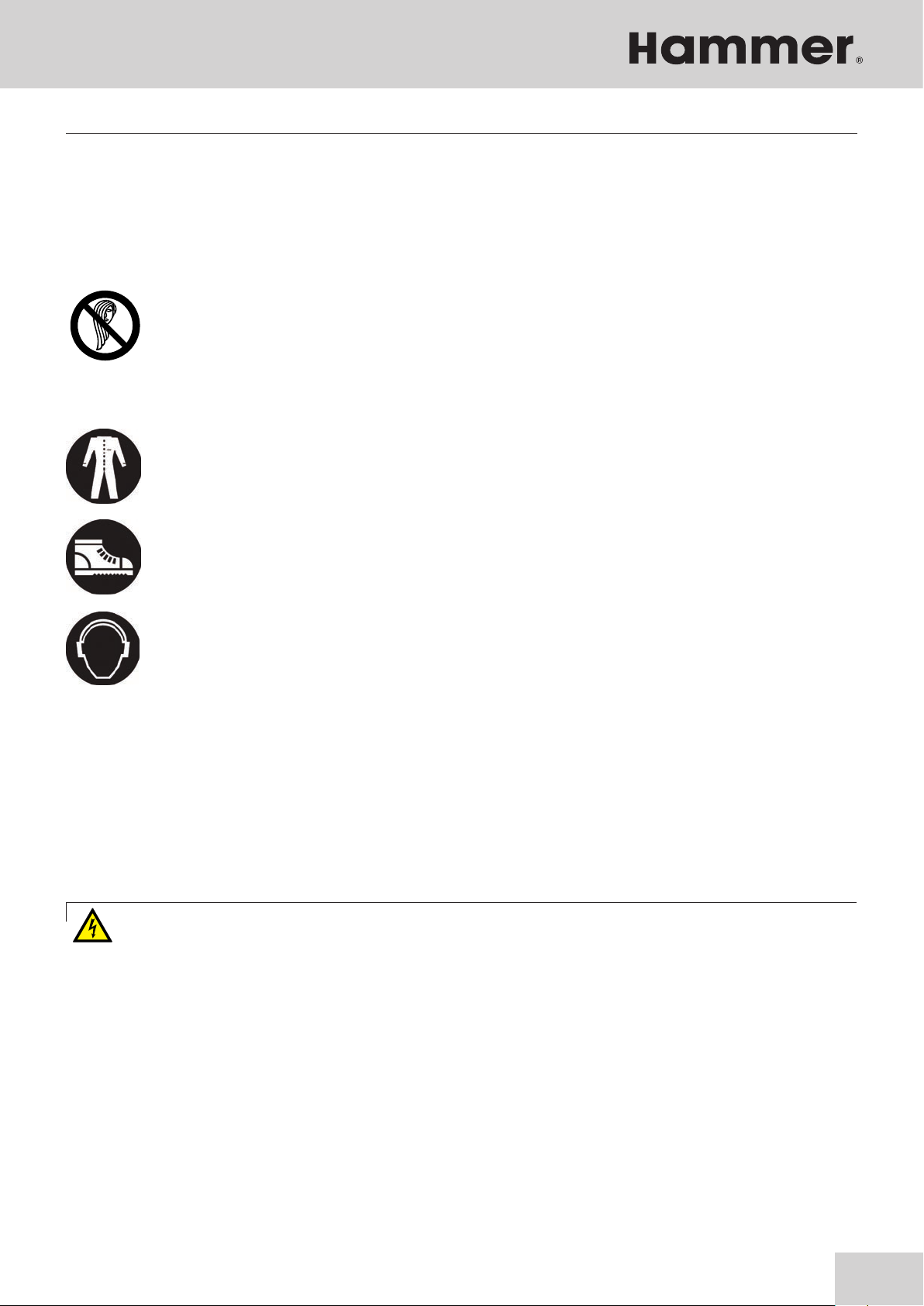
Persons with long hair who are not wearing a hairnet are not permitted to work on or with the machine!
When working on or with the machine, the following must always be worn by personnel:
Protective clothes
Sturdy, tight-fitting clothing (tear-resistant, no wide sleeves, no jewellery (rings, bracelets, necklaces, etc.)).
Protective footwear
To protect the feet from heavy falling objects and prevent sliding on slippery floors.
Hearing protection
To protect against loss of hearing.
2.8 Machine hazards
The machine has undergone a hazard analysis. The
design and construction of the machine are based on the
results of this analysis and correspond to state-of-the-art
technology.
The machine is considered operationally safe when used
Warning! Danger! Electric current!: Electrical energy can cause serious bodily injury. Damaged insulation
materials or defective individual components can cause a life-threatening electrical shock.
properly.
Nevertheless, there are some remaining risks that must be
considered.
The machine runs at high electrical voltage.
• Before carrying out any maintenance, cleaning and
repair work, switch off the machine and ensure that it
can not be accidentally switched on again.
• When carrying out any work on the electrical equip-
ment, ensure that the voltage supply is completely
2.9 Other risks
• Hearing damage as a result of high noise levels
• Health impairments due to the inhalation of airborne
isolated.
• Do not remove any safety devices or alter them to
prevent them from functioning correctly.
particles, especially when working with beech and
oak wood.
11
Page 12

Bandsaw
N2-35
Declaration of Conformity
3 Declaration of Conformity
EG-Declaration of Conformity
According to Machine Guidelines 2006/42/EG
We hereby declare that the machine indicated below, which corresponds to the design and construction of the model
we placed on the market, conforms with the health and safety requirements as stated by the EC.
Manufacturer:
Product designation:
Make:
Model designation:
The following EC guidelines were applied:
The following harmonised norms were applied:
FELDER KG
KR-FELDER-STR.1
A-6060 Hall in Tirol
Bandsaw
Hammer
N2-35
2006/42/EG
2014/30/EU
EN 1807-1
This EC Declaration of Conformity is valid only if the CE label has been affixed to the machine.
Modifying or altering the machine without the express written agreement of the manufacturer shall render the
warranty null and void.
The signatory of this statement is the appointed agent for
the compilation of the technical information.
Hall in Tirol, 1.1.2018
12
Johann Felder, Managing Director FELDER KG
KR-FELDER-STR.1 • A-6060 Hall in Tirol
Page 13

Bandsaw
N2-35
Declaration of Conformity
13
Page 14

4 Specifications
4.1 Dimensions and weight
Bandsaw
N2-35
Specifications
H
L
Fig. 4-1: Total size
Machine (L x W x H) N2-35
Total size 770 x
670 x
1310 (H) /1700 mm (H+S)
Package size 590 x
460 x
1300 mm
Net weight 100 kg
Bandsaw N2-35
Cutting height 235 mm
Rip capacity max. 340 mm
- || - Rip fence 295 mm
Saw blade length 2630 mm
Saw blade width 6-20 mm
Saw blade speed 17 m/sec
Wheel diameter 350 mm
Table size 400 x 548 mm
Tiltable table -5° max. +45°
S
B
14
Page 15

Bandsaw
N2-35
Specifications
4.2 Operation and storage conditions
Operating/room temperature +10 to +40 °C
Storage temperature –10 to +50 °C
4.3 Electrical connection
Machine Alternating-current motor Three-phase current motor
N2-35
Motor voltage 1x 230 V motor frequency 50/60 Hz Motor power S1 1 kW -
*) S6 = operation under load and intermittent service; 40% = relative operating factor
mains voltage according to specification plate ±10%
Safeguarding see circuit plan
Power supply cord (H07RN-F) 3x2,5 mm²/ 5x2,5 mm²
Triggering characteristic C (D*)
*) if starting up is slow, caused by large swinging masses
4.4 Dust Extractors
The machine has to be connected to a dust extractor. The
connection values and the position of the connection port
are shown on the picture.
The air speed at the connection point has to be a minimum of 20 m/s for materials with a humidity less than
12 %.
The air speed should be increased to 25–28 m/s to extract dust from more humid materials (over 12 %).
Fig. 4-2: Connection ports
! Connection ports 100 mm
!
Only flame resistant vacuum hoses can be used, conforming to DIN 4102 B1 and any other safety regulations
in effect
Extraction connection-Ø 100 mm
Air speed 20 m/s
Min. depression 1138 Pa
Volume flow min. 565 m³/h
15
Page 16
4.5 Noise emission
Bandsaw
N2-35
Specifications
The given values are emission values and not safe workplace values. Although there is a correlation between
emission and immission levels, it is not possible to state
whether increased safety measures are required.
Factors which can considerably influence the present
immission level at the workplace include the duration of
exposure, the character of the work area and other influences in the neighbouring area.
Note:
To keep the noise emission as low as possible, always use sharpened tools and operate the machine
at the correct speed.
Do not overload the machine! It is safer and performs better if operated within its power range.
Ear protection must always be worn; however, such protection cannot be considered a substitute for
properly sharpened tools.
All values in dB(A) and with a measurement uncertainty factor of 4 dB(A).
Acceptable workplace values may also vary from country
to country. However, this information should help the user
to better assess the hazards and risks.
Depending on the installation location and other
variables, the resulting noise emission can differ by up to
4 db (A) from the given values.
Model L Aeq LW (A) Lpc
N2-35 73,3 dB (A) 84,1 dB (A) 2,3 mW < 130 dB (A)
16
Page 17

Bandsaw
N2-35
Specifications
17
Page 18
5 Setting up the machine
5.1 Overview
Setting up the machine
"
%
CL
Bandsaw
N2-35
BR
BT
BP
$
BU
BO
BL
#
(
&
/
BS
)
BN
CN
CL
CM
(
BM
BQ
!
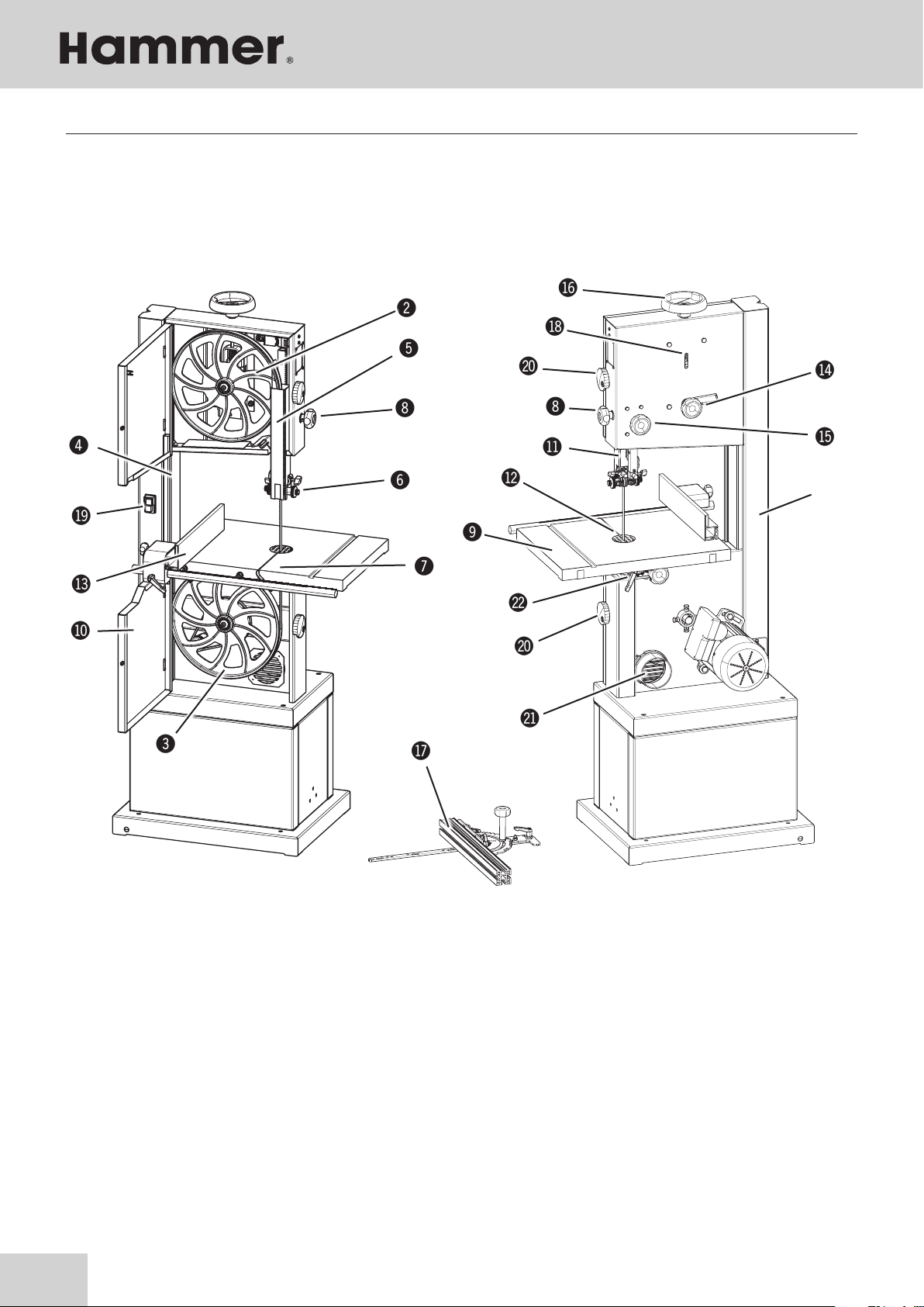
Fig. 5-1: Overview
! Machine base-frame
" Upper wheel
# Lower wheel
$ Rising part of saw blade
% Falling part of saw blade
& Upper blade guide
/ Lower blade guide (Optional)
* Blade guide height adjustment
) Work bench
BL Wheel door
BM Height adjustable protection device
BN Table insert
18
BO Guide fence
Saw blade track - Adjuster hand wheel and clam-
BP
ping leverl
BQ Lock wheel - Blade guide height adjustment
BR Blade tension hand wheel
BS mitre fence (Accessories)
BT Saw blade tension indicator window
BU On/Off switch
CL Lock wheel - Wheel door
CM Vacuum connector
Tiltable table (Adjuster hand wheel and clamping
CN
lever)
Page 19

Bandsaw
N2-35
5.2 Data plate
Setting up the machine
KR-FELDER-STR.1
A - 6060 HALL in Tirol
AUSTRIA
Tel.: 0043 (0)5223 / 45 0 90
Tax.: 0043 (0)5223 / 45 0 99
TYPE :
NR. :
Baujahr / year of constr. / annee de constr. :
Motordaten:
Fig. 5-2: Data plate
info@hammer.at / www.hammer.at
HZ:PH:V:
A:KW:
5.3 Automatic braking system
Your machine is equipped with an automatic braking
unit. The brake is a maintenance-free DC braking unit.
All necessary adjustments are done by FELDER KG.
The data plate displays the following specifications:
• Manufacturer information
• Model designation
• Machine number
• Voltage
• Phases
• Frequency
• Motor power
• Power supply
• Year of construction
• Motor specifications
Please contact the FELDER KG service department, if problems or a fault- function should occur!
5.4 Safety break switches
!
Fig. 5-3: Lock system
The machine only runs when the end switch in the inside
of the machine frame is engaged by the locking device
! Lock system
" Break switch
"
19
Page 20

Transport, packaging and storage
6 Transport, packaging and storage
6.1 Safety instructions
Attention! Risk of material damage!
!
The machine can be damaged or destroyed if it is subjected to improper handling during transport.
Warning! Risk of injury!
There is a risk of injury as a result of falling parts while transporting, loading or unloading the machine.
For this reason the following safety instructions must be observed:
Bandsaw
N2-35
• Never lift loads over a person.
• Always move the machine with the utmost care and
caution.
• Only use suitable lifting accessories and hoisting
devices that have a sufficient load-carrying capacity.
• Never lift the machine by its protruding parts (e.g.
sliding table).
• Consider the machine's centre of gravity when transporting it (minimise the risk of it tipping over).
• Take measures to prevent the machine from slipping
sideways.
• Ropes, belts or other hoisting devices must be
equipped with safety hooks.
6.2 Transport inspection
Upon arrival, inspect the shipment to ensure that it is
complete and has not suffered any damage.
If any transport damage is visible, do not accept the delivery or only accept it with reservation. Record the scope
of the damage on the transport documents/delivery note.
Initiate the complaint process.
• Do not use torn or worn ropes.
• Do not use knotted ropes or belts.
• Ensure that ropes and belts do not lie against sharp
edges.
• Transport the machine as carefully as possible in
order to prevent damage.
• Avoid subjecting the machine to shocks.
When transporting the machine overseas, ensure that
the packaging is airtight and that a desiccant is
added to protect the metal parts against corrosion.
For all defects that are not discovered upon delivery, be
sure to report them as soon as they are recognised as
damage claims must be filed within a certain period, as
granted by law.
6.3 Packaging
If no agreement has been made with the supplier to take back the packaging materials, help to protect the environment by reusing the materials or separating them according to type and size for recycling.
Attention! Dispose of the packaging materials in an environmentally friendly way and always in
accordance with local waste disposal regulations. If applicable, contract a recycling firm to dispose
of the packaging materials.
Note: Help preserve the environment!
Packaging materials are valuable raw materials and in many cases they can be used again or
expediently reprocessed or recycled.
20
Page 21

Bandsaw
N2-35
Transport, packaging and storage
6.4 Storage
Keep items sealed in their packaging until they are
assembled/installed and be sure to observe the stacking and storage symbols on the outside of the packaging.
Store packed items only under the following conditions
• Do not store outdoors.
• Store in a dry and dust-free environment.
• Do not expose to aggressive substances.
• Protect from direct sunlight.
• Avoid subjecting the machine to shocks.
• Storage temperature: -10° to +50° C.
• Maximum humidity: 60 %.
• Avoid extreme temperature fluctuations (condensation
build-up).
• Apply a coat of oil to all bare machine parts (corrosion protection).
6.5 Transport
Attention! Risk of material damage!
!
Transport the machine according to the enclosed transport and assembly instructions!
The machine must not be lifted by the work table, sliding table or base! Ropes, belts and chains
may only be fastened to the base of the machine.
Note:
The transportation width is well under 1000 mm. This makes it possible to transport the machine
through doorways.
• When storing for longer than 3 months, apply a
coat of oil to all bare machine parts (corrosion protection). Regularly check the general condition of all
parts and the packaging. If necessary, refresh or reapply the coat of
anti-corrosive agent.
• If the machine is to be stored in a damp environment,
it must be sealed in air-tight packaging and protected
against corrosion (desiccant).
6.5.1 Transport locking device
Fig. 6-1: Transport locking device
The machine is partly assembled when delivered on the
pallet
The machine can be transported with a crane, forklift,
pallet jack or rolling carriage.
21
Page 22

6.5.2 Transport with a crane
Attention! Risk of material damage!: Do not lift the machine by its work table, extension frames or hand-
!
wheels.
Align the straps correctly and check that the machine is properly supported. The machine must be raised slowly and very carefully to prevent the load from slipping.
!
A
Bandsaw
N2-35
Transport, packaging and storage
For crane transport only belts may be used.
Hang the straps in position A.
!Belts
Fig. 6-2: Transport with a crane
6.5.3 Transport with a rolling carriage
Note:
The rolling carriage and the lifting bar (option) facilitate the task of transporting the machine.
Accessories Order no.:
Rolling carriage - 503-142
Lifting bar - 500-149
Fig. 6-3: Transport with a rolling carriage
22
Page 23

Bandsaw
N2-35
Transport, packaging and storage
23
Page 24

7 Setup and installation
7.1 Safety instructions
Warning! Risk of injury!: Improper assembly and installation can lead to serious physical injury or equipment damage. For this reason, this work may only be carried out by authorised, trained personnel who
are familiar with how to operate the machine and in strict observance of all safety instructions.
Bandsaw
N2-35
Setup and installation
• Ensure that there is sufficient space to work around
the machine. Ensure there is ample distance between
the machine and other solid constructions such as a
walls or other machines.
Warning! Danger! Electric current!: Work on electrical fittings may only be carried out by qualified
personnel and in strict observance of the safety instructions.
Before assembling and installing the machine, check to
make sure it is complete and in good condition.
Warning! Risk of injury!: An incomplete, faulty or damaged machine can lead to serious physical injury or
equipment damage. Only assemble and install the machine if the machine and its parts are complete and
intact.
Attention! Risk of material damage!: Only operate the machine in ambient temperatures from +10°C to
!
+40°C. If the instructions are not followed, damage may occur to bearings.
• Keep the work area orderly and clean. Components
and tools that are not put in their correct place or put
away may be the cause of accidents!
• Install the safety equipment according to the
instructions and check that it functions properly.
7.2 Setup
24
Installation site requirements:
• Operating/room temperature: +10° to +40°C.
• Ensure that the work surface is sufficiently stable and
has the proper load-bearing capacity.
• Provide sufficient light at the workstation.
• Ensure there is sufficient clearance for or from
neighbouring workstations.
• Risk of injury! Keep machines, tools and accessories
etc. out of the reach of children.
• Vacuum hoses and electrical wires should be layed
in such a way as to avoid tripping over them.
Page 25

Bandsaw
N2-35
Setup and installation
7.2.1 Assemble machine frame (Option)
Warning! Heavy dead weights can easily cause an injury
To facilitate assembly, ensure the presence of a minimum of one additional people.
Note:
!
During the assembly of the machine frame, first loosely connect all parts.
Finally, tighten all screws.
Ensure the correct position of the drill holes when mounting the base walls!
!
Fig. 7-1:Assembly - Machine frame
Hinten / Backside
#
"
!
Due to technical reasons, the machine is delivered in a
partly dismantled state.
!2 x base wall - long
"2 x base wall - short
#18 x Screws, Nuts, Shims
$1 x Base
Assembly - Machine frame:
1. Connect the base walls long and short with screws,
nuts and washers.
2. Tighten the screws once the angularity is set.
3. Fasten the base plate to the mounted base walls.
$ !
Fig. 7-2:Assembly - Machine frame
Vorn / Front
25
Page 26

Setup and installation
7.2.2 Attaching the band saw to the machine frame
Warning! Heavy dead weights can easily cause an injury
To facilitate assembly, ensure the presence of a minimum of one additional people.
Note:
If the machine stand is not mounted on the machine frame, the machine must be placed on a stable and level
surface at least 390 mm high.
Bandsaw
N2-35
"
min. 4 mm
Fig. 7-3: Assembly - Bandsaw
!
#
Assembly - Bandsaw:
1. Do not screw in the fastening screws completely. The
distance between the bottom edge of the screw head
and the machine base should be at least 4 mm.
!
2. Tighten the screws once the angularity is set. Move the
machine in the direction of the slots.
3. Screw in the socket head cap screw with the
hex key (can be reached via the bore).
!4 x Fixing screws
"Slot
#Bore
26
Page 27

4 x
Bandsaw
N2-35
Setup and installation
7.2.3 Setting up the work table / Angle adjustment
Fasten the worktable to the clamp with screws and
!
washers.
! Washers
" Screw
!
# clamp
#
$ Work bench
"
Fig. 7-4: Work table
!
"
Fig. 7-5: 90° to saw band run
#
#
Disconnect the machine from the mains supply.
Levelling the machine / See chapter entitled 7.2.5
Tension saw blade / See chapter entitled 8.3
Angle adjustment: 90° to saw band run
Loosen the clamping lever.
Tilt the work table until it rests on the stop screw.
Place a 90° angle between the running surface of
the saw band and the working table.
If the 90° in the initial position is not correct, adjust
the stop screw accordingly.
Check the 90° angle once the clamping lever is back
in place.
! Work table
" Clamping lever
# Fence screw
$ 90° - Angle
Fig. 7-6: 90° to the saw band back
27
Page 28

Y
X
Y>X Y<X
X1
X2
X1=X2=18 mm
7.2.4 Assembly - Rip fence
"
!
Bandsaw
N2-35
Setup and installation
Use a nut to mount the fence rail to the machine ta-
ble.
Slide the premounted fence onto the track.
! Nut
" Fence rail
Fig. 7-7: Rip fence
"
#
Fig. 7-8: Height adjustment - Fence rail
!
"
!
Height adjustment - Fence rail:
Adjust the distance: 18 mm
(This setting has to be exact.)
Loosen the lock nuts.
Place a 90° angle at the front edge of the table.
Adjust the distance X1.
Turn the setting nut by hand.
Adjust the distance X2.
Tighten the lock nuts.
Check the setting and readjust if necessary.
! Locking nut
" 90°- Angle
# Fence rail
Setting the rip fence:
Move the rip fence to the left.
Measure the distance Y and X (Distance between
stop ruler and table groove).
The values X and Y must be equal.
Loosen the right nut.
The angle can be adjusted by twisting the adjusting
screw.
Y > X :turn - Anti-clockwise
Y < X :turn - Clockwise
Counter the right nut again.
Check the setting and readjust if necessary.
Fig. 7-9: Setting the rip fence
28
#
! Rip fence
" Nut - Right
# Adjusting screw
Page 29

Bandsaw
N2-35
Setup and installation
7.2.5 Positioning and levelling the machine
Note:
There are 4 threaded holes located in the base plate of the machine where the levelling screws supplied with
the machine can be screwed into. (optional)
!
#
!
"
The following points are important for a correct and efficient machine installation:
• Position the machine with the aid of a spirit level to en-
sure that the machine functions precisely and operates
smoothly.
• Compensate for uneven floors with the „adjusting
screws“ or bolster the machine
• The machine should be bolted to the floor with M10
screws for optimum stability, however take care not to
overtighten the fastening bolts as this will increase vibrations. It is advisable to place vibration dampening
pads between the floor and the machine.
• Install the machine in such a way as not to amplify the
vibrations and machine noise.
• Ensure that workplace lighting is adequate.
• If the machine is to be installed between other ma-
chines, leave at least 80 cm distance in-between, in
order to avoid collisions when cutting large workpieces and to allow the use of equipment such as roll
supports and additional tables.
Fig. 7-10: Floor mounting
!Screws
"Adjusting screw
#Locking nut
29
Page 30

7.3 Electrical connection
Warning! Danger! Electric current!
Work on electrical fittings may only be carried out by qualified personnel and in strict observance of the
safety instructions.
Checking the loop impedance and the suitability of the overcurrent protective device must take place at the
location where the machine is to be commissioned!
Attention! Risk of material damage!
!
Before hooking up the machine to the power supply, compare the specifications on the data plate with
those of the electrical network. Only hook up the machine if the two sets of data correspond to each other.
The electrical outlet must have the appropriate socket (for a three-phase alternating current motor, CEE).
Note: Do not open the machine's switch box unless you have the express consent of the Hammer service
department Violating this stipulation shall render the right to make claims under the warranty null and
void.
Bandsaw
N2-35
Setup and installation
Attention! Risk of material damage!
!
The machine must be secured with an automatic fuse.
Fig. 7-11: Direction of the Motor rotatation
1. Connect the plug to the power supply.
2. Switch on and let the machine run briefly.
3. While the motor is running, check its direction of
rotation.
4. Should a change in the direction of rotation be
necessary, switch the two phases on the power cable.
Electrical connection requirements
• The machine must be earthed with electrical
conductors.
• The voltage fluctuations in the mains supply may not
exceed ±10 %.
• The switch cabinet must be fitted with a circuit
breaker (DIN VDE 0641).
• Power supply cable H07RN-F at least 5x 2,5 (rotarycurrent motor) or 3x 2,5 (alternating-current motor).
• Safeguarding/Power supply cord:
see “Technical data”
• The power supply cable must be protected against
damage (e.g. armoured conduit).
• The power supply cable must be laid in such a way
so it does not overbend or chafe and there is no risk
of tripping over it.
30
Note: The machine's power cable is delivered with an open cable end, i.e. without a plug.
The operator is responsible for fitting the machine‘s power cable with a suitable plug in accordance with
any country’s specific regulations.
Page 31

Bandsaw
N2-35
Setup and installation
31
Page 32

8 Operation
8.1 Safety instructions
Warning! Risk of injury! Improper operation may lead to severe physical injury or material damage. For
this reason, this work may only be carried out by authorised, trained personnel who are familiar with how
to operate the machine and in strict observance of all safety instructions.
Bandsaw
N2-35
Operation
Before starting work:
• Before assembling and installing the machine, check
to make sure it is complete and in good condition.
• Ensure that there is sufficient space to work around
the machine.
• Keep the work area orderly and clean. Components
and tools that are not put in their correct place or put
away may be the cause of accidents!
• Ensure that all safety devices have been installed
properly.
• Adjustments to the machine or tool replacement may
only be conducted once the machine has stopped.
• Only clamp authorised tools to the machine.
• Install the dust extraction system according to the
instructions and test its function.
• Only machine workpieces that can be safely placed
on the machine and guided.
• Carefully inspect workpieces for foreign matter (nails,
screws) which might impair processing.
• Support long workpieces with additional surface
equipment (e.g. Table extensions, roll supports).
• Ensure that each unit is rotating in the proper direction.
• Keep tools for handling short and narrow workpieces
close at hand.
• Before switching on the machine, always check to make
sure that there are no other persons in the immediate
vicinity of the machine.
During operation:
• When changing to another workpiece or if a
malfunction occurs, first switch off the machine and
then secure it against being switched on again
accidentally.
• Do not switch off, circumvent or decommission
protective and safety devices during operation.
• Do not overload the machine! It is safer and performs
better if operated within its power range.
When working on or with the machine, the following
must be strictly observed:
• Persons with long hair who are not wearing a hairnet
are not permitted to work on or with the machine!
• It is prohibited to wear gloves while working on or
with the machine.
When working on or with the machine, the following
must always be worn by personnel:
• Sturdy, tight-fitting clothing (tear-resistant, no wide
sleeves, no jewellery (rings, bracelets, necklaces,
etc.)).
• Protective footwear To protect the feet from heavy
falling objects and prevent sliding on slippery floors.
• Hearing protection To protect against loss of hearing.
32
Attention! Risk of material damage!
!
Only operate the machine in ambient temperatures from +10°C to +40°C. If the instructions are not followed, damage may occur to bearings.
Improper use such as cutting too tight a radius or with too much cutting pressure could cause friction and
lead to sparks being generated by the blade guides.
In order to prevent sparks being generated, it is recommended that Super Glide (article number 10.0.010)
is used on a regular basis (sprayed on to the guides).
Page 33

Bandsaw
N2-35
8.2 Blade selection and maintenance
Selecting the type of saw blade and its width, depends on the material to be cut and the type of cut:
• Narrow saw blades are designed for curved and circular cuts, whereas wide saw blades are designed for straight cuts.
• A fine-toothed saw blade is required for hard wood, whereas a coarse-toothed saw blade is required
for soft wood.
Operation
The following saw blades may be used:
#
100
40
10 15 20
!
Fig. 8-1: Saw blades
150
200
25
"
!
N2-35 - Length: 2630 mm
Art. No.
13.7.3506 6 mm 4,0 mm
13.7.3510 10 mm 6,0 mm
13.7.3515 16 mm 6,0 mm
13.7.3520 20 mm 8,0 mm
SB ZT
! Blade width (SB)
" Radius cut
# Tooth spacing (ZT)
The gap between the individual teeth should be large
enough to carry the material chips and to throw them
away. If the gap is too small, the blade will overheat and
rupture.
Do not use kinked, ruptured or bent saw blades.
For soft wood, the set should be a max. of twice the
thickness of the saw blade and for hard wood, a max. of
1.5 times the thickness of the saw blade.
Fig. 8-2: Release saw band tension
Attention! Once the machine is no longer in use, loosen the belt tension and place an appropriate
warning sign on the machine. This will thus prevent damage to the wearing surface of the wheels. (see illustration)
Change blunt blades and have them sharpened by a
specialist workshop or purchase a new saw blade.
It is recommended to use only high quality saw blades.
DO NOT
USE !
33
Page 34

8.3 Saw blade replacement/tension
Warning!
Be wary of sharp edges to avoid cutting yourself, in particular when changing the tooling.
%
$
#
!
"
Bandsaw
N2-35
Operation
1. Disconnect the machine from the mains supply.
2. Remove table insert and positioning pin.
Open wheel door.
3. Move the upper and lower saw band guide away
from the saw blade.
4. Loosen the belt tensioning handwheel by turning it
counterclockwise. Unthread old blade through the
machine table.
5. Place new saw blade over both wheels (note the di-
rection of the cut!).
6. Check the saw blade tension and if required, adjust
with the hand wheel. The correct tension is displayed
on the belt tension display, the displayed value has
to correspond to the belt width.
7. Release the clamping lever and set the saw blade
track using the hand wheel: see sketches
> 16
min 3 mm
1/2 1/2
&
Fig. 8-3: Saw blade replacement
mm
6 -16
Sketches
%
Attention!
!
The saw band run should only be adjusted with
the hand wheel on the upper wheel.
If the belt run cannot be adjusted with the upper
wheel, an adjustment must be made on the lower wheel. See chapter entitled 8.3.1
8. Turn the wheels manually and ensure that the saw
belt glides properly around the wheels and does not
collide with any solid machine parts.
9. Clamp the clamping lever.
10. Adjust the upper and lower saw band guides to the
new saw blade.
11. Install the safety equipment according to the
instructions and check that it functions
properly.Loosen the belt tensioning handwheel by
turning it counterclockwise.
! Positioning pin
" Table insert
# Handwheel - Saw blade track
$ Clamping lever
% Blade tension hand wheel
& Scale - saw belt tension
34
Page 35

Turn set screw 1 counterclockwise.
Bandsaw
N2-35
8.3.1 Setting - Saw blade track / Lower wheel
Attention! Risk of material damage!
!
The saw band run should only be adjusted with the hand wheel on the upper wheel.
If the belt run cannot be adjusted with the upper wheel, an adjustment must be made on the lower wheel.
Only the vertical adjusting screws for adjusting the lower wheel can be changed.
Proceed very cautiously with the settings described here.
Operation
Measure the distance Y and X (from the front edge of the
wheel to the machine frame). The values X and Y must be
equal.
X
Setting - at X>Y:
Loosen the lock nuts.
Turn set screw 2 counterclockwise.
Y
X
X < Y
$
Y
X
X > Y
$
Y
Turn set screw 1 clockwise until the pin is fixed.
Tighten the lock nuts.
Turn the wheels manually and ensure that the saw
belt glides properly around the wheels and does not
collide with any solid machine parts.
If necessary, readjust the upper wheel.
Check the setting and readjust if necessary.
Setting - at X<Y:
Loosen the lock nuts.
Turn set screw 1 counterclockwise.
Turn set screw 2 clockwise until the pin is fixed.
Tighten the lock nuts.
Turn the wheels manually and ensure that the saw
belt glides properly around the wheels and does not
collide with any solid machine parts.
If necessary, readjust the upper wheel.
Check the setting and readjust if necessary.
!
#
#
$
"
Fig. 8-4: Setting - Saw blade track/ Lower wheel
! setscrew 1(Vertical)
" setscrew 2(Vertical)
# Locking nut
$ Pin
35
Page 36

8.4 Tilting the table
Bandsaw
N2-35
Operation
The machine working table can be tilted up to an angle
from -5° up to +45°
$
!
"
Fig. 8-5: Tilt
#
! Work bench
" Clamping lever
# Lever
$ Fence - 0°
8.5 Adjusting the saw blade guide
Adjusting the angle:
1. To tilt, remove the table padding to enable the saw
belt to move through the table unimpeded.
2. Open the clamping screw with the supplied spanner
and tilt the table to the desired angle, which is displayed on the mitre scale.
3. Tighten the clamping screw again.
Tilt -5°:
1. Swing away the stop
2. Adjusting the angle
3. To tilt the table back to its normal position, loosen the
clamping screw once again and tilt the table up to
the stop in the 0° position and clamp it in that position.
(Swing back the stop)
Warning! Risk of injury!:
Do not change settings whilst the machine is in operation!
8.5.1 Height adjustable protection device
"
!
Fig. 8-6: Bearings
The upper saw blade guide has to be lowered as closely as possible to the work-piece (5–10 mm). To set
the height, open the clamping screw and turn the hand
wheel until the desired height has been reached. Tighten
the clamping screw once again.
! Clamping screws
" Blade guide height adjustment
36
Page 37

B
A
Bandsaw
N2-35
8.5.2 Saw blade guide - upper
Attention! Risk of material damage!
!
The saw band guides can only be adjusted after the band tension and band run have been set correctly. The
saw band guides must be readjusted after each saw band change.
Make the following settings precisely to prevent possible ignition sparks.
Operation
B
$
#
"
B
!
A
!
$
#
A
B
Setting the side guiding elements
direction A
Loosen the clamping screw.
Move the saw band guide on the adjusting pin.
The side guides must be positioned behind the main
teeth of the saw blade, and even when cutting, must
not be able to come in contact with the teeth.
Tighten the clamping screw.
direction B
Loosen the thumb nut.
Adjust the distance with the adjusting screw.
The side guide rollers should touch the saw blade
slightly so as to obtain a straight and vibration-free
cut.
Secure the thumb nut.
! Clamping screw
" Sliding link pins
# Thumb nut
$ setscrew
Fig. 8-7: Setting the side guiding elements
!
!
Fig. 8-8: Setting the rear guides
Setting the rear guides
Loosen the clamping screw.
Move the back guide.
Adjust the back guide parallel to the saw band back
with a small distance.
Tighten the clamping screw.
"
! Clamping screw
" back guide
37
Page 38

Operation
8.5.3 Saw blade guide - down (Option)
Attention! Risk of material damage!
!
The saw band guides can only be adjusted after the band tension and band run have been set correctly. The
saw band guides must be readjusted after each saw band change.
Make the following settings precisely to prevent possible ignition sparks.
A
"
B
B
$
B
A
!
A
!#
Bandsaw
N2-35
Setting the side guiding elements
direction A
Loosen the clamping screw 1.
Displace the guide part over the guide rod.
The side guides must be positioned behind the main
teeth of the saw blade, and even when cutting, must
not be able to come in contact with the teeth.
Clamp the clamping screw 1.
direction B
Loosen the clamping screw 2.
Slide the lateral guide on the adjusting bolt.
The side guide rollers should touch the saw blade
slightly so as to obtain a straight and vibration-free
cut.
Clamp the clamping screw 2.
Fig. 8-9: Setting the side guiding elements
"
!
Fig. 8-10: Setting the rear guides
#
! Clamping screw 1
" Clamping screw 2
# Guide piece
$ Sliding link pins
Setting the rear guides
Loosen the clamping screw.
Adjust the back guide with the set screw.
Adjust the back guide parallel to the saw band back
with a small distance.
Tighten the clamping screw.
! Clamping screw
" back guide
# setscrew
38
Page 39

Bandsaw
N2-35
Operation
8.6 Switching on the machine / Switching off the machine
Warning!: Risk of injury due to insufficient preparation!
It is only permitted to switch on the machine if, for the work at hand, the required preconditions are fulfilled
and any preliminary work is completed. Therefore, the adjusting, fitting and operating instructions (see the
corresponding chapters) must be read before switching on the machine.
Attention!: The machine will not start with the doors open and will automatically stop if doors are opened
!
during operation. (Only valid for the CE-version !)
The bandsaw has an On- and Off switch.
Green push button:
Switch machine on
!
Fig. 8-13: On- and Off switch
8.7 Authorised working techniques
8.7.1 Longitudinal cut along the marked line
Red push button:
Switch off the machine.
! On/Off switch
Fig. 8-14: Rip cut
All uses which differ from the following work techniques
have not been intended for this machine and are therefore
not authorised.
Feed the workpiece with constant speed and pressure forwards without applying sideways pressure Do not interrupt
the cut and do not pull the workpiece backwards When
cutting large pieces, use appropriate table extensions or
roll supports.
39
Page 40

Operation
8.7.2 Cutting round workpieces in the transverse direction
Use an appropriate device with the minimum measurements as depicted in Fig. to avoid the workpiece twisting
during the cutting process.
Fig. 8-15: Cutting a circular workpiece
8.7.3 Cutting workpieces on the upright edge
Bandsaw
N2-35
Use an auxiliary fence with the minimum measurements
to guide the workpiece safely.
Fig. 8-16: Auxiliary fence
8.7.4 Longitudinal cut of narrow or thin workpieces with the longitudinal guide fence
Use a push stick as depicted in Fig. to prevent your
hands from coming too close to the saw blade.
!
Fig. 8-17: Push stick
40
!Push stick
Page 41

Bandsaw
N2-35
8.7.5 Mitre cuts
Fig. 8-18: Mitre cuts
Operation
Use auxiliary equipment as depicted in the figure.
8.7.6 Circular cuts
Use auxiliary equipment as depicted in the figure.
Accessories Order no.:
01.1.300
Fig. 8-19: Circular cuts
8.7.7 Diagonal cross-cut of rectangular workpieces
Use auxiliary equipment as depicted in the figure.
Fig. 8-20: Cross cut
41
Page 42

9 Service
9.1 Safety instructions
Warning! Risk of injury!: Improper adjustment and setup work can lead to serious physical injury or
material damage. For this reason, this work may only be carried out by authorised, trained personnel who
are familiar with how to operate the machine and in strict observance of all safety instructions.
Bandsaw
N2-35
Faults
• Before beginning any maintenance work on the
machine, switch it off and secure it against accidentally being switched on again.
• Before commencing any work with the machine,
inspect it to ensure that it is complete and in
technically good condition.
Warning! Danger! Electric current!: Work on electrical fittings may only be carried out by qualified
personnel and in strict observance of the safety instructions.
9.2 Tightening/replacing the drive belt
Over time, the drive belt will lose its capacity to transmit
power. At this point, the drive belt must be re-tensioned
or replaced.
!
• Ensure that there is sufficient space to work around
the machine.
• Keep the work area orderly and clean. Components
and tools that are not put in their correct place or put
away may be the cause of accidents!
• Install the safety equipment according to the
instructions and check that it functions properly.
The drive belt must be inspected monthly; if tears are
discovered, the drive belt must be replaced.
Following the first few operating hours, the belt tension
has to be controlled, as the belt will extend.
To check the tension, press inwards onto the belt in the
middle with a weight of 3-4 kg.
The belt deflection should not be more than 5-6 mm.
Retensioning the drive belt:
1. Loosen the nuts.
2. The motor must be swivelled to tension the drive belt.
3. Tighten the nuts.
Fig. 9-1: Drive belts
! Nut
42
It is important to always maintain the correct belt tension,
as belts which are too loose will weaken the drive power
!
Attention! Risk of material damage!: Do not over-tension the drive belt!. Tighten the motor only until sufficient power transmission is ensured.
and the brake power and belts which are overtightened
will lead to overheating.
Page 43

Bandsaw
N2-35
"
!
!
Faults
Replace the drive belt. :
Removing the saw blade See chapter entitled: Saw blade
replacement/tension
1. Open the locking nut until the v-belt moves slightly
away from the drive pulley.
2. Loosen the clamping screw.
Disassembling the lower wheel.
Control: Defect or soiled wheel running surfaces
3. Place the new drive belt on the wheel.
Slide the wheel onto the shaft..
Tighten the clamping screw.
5. Attach the belt to the motor pulley.
Ensure that the belt is seated properly with a few
manual turns!
6. Retensioning the drive belt
#
%
Fig. 9-2: Replace the drive belt.
Attention! Risk of material damage!:
Check the rubber surface of the wheels regularly for damage. In case of excessive wear, the wheels must
be replaced.
9.3 Upper wheel - Replace
$
! Nut
" Motor pulley
# Clamping screw
$ Lower wheel
% Drive belt
Removing the saw blade See chapter entitled: Saw blade
replacement/tension
1. Loosen the clamping screw.
2. Disassembling the upper wheel
3. Slide the wheel onto the shaft.
4. Tighten the clamping screw.
!
Fig. 9-3: Disassembling the upper wheel
"
! Clamping screw
" Upper wheel
43
Page 44

9.4 Cleaning and lubrication
Bandsaw
N2-35
Faults
Clean the inside of the machine regularly with a vacuum
to remove saw dust deposits and remove resin deposits
from the wheel surfaces. The wheel bearings are sealed
and do not need to be lubricated again.
The following components are to be lubricated:
• Adjustment - saw belt tension
• Gearbox - Height adjustable protection device
• Tiltable table
Regularly control the cleanliness of the wheel wearing
9.4.1 Adjustment - saw belt tension
A
A
!
"
Fig. 9-4: Adjustment - saw belt tension
surfaces, especially after resinous materials or chipboards have been cut. Only clean the wearing surfaces
once the machine is idle and ensure that the wearing
surfaces are not damaged during the process.
1. Before beginning any maintenance work on the
machine, switch it off and secure it against accidentally being switched on again.
2. Open wheel door
Removing the saw blade See chapter entitled: Saw
blade replacement/tension
3. In spots A:
Lubricate with regular machine grease.
4. Turn the belt tensioning handwheel all the way down
and turn it all the way up again.
5. Installing the saw blade
! Wheel door
" Adjustment - saw belt tension
# Blade tension hand wheel
9.4.2 Gearbox - Height adjustable protection device
1. Before beginning any maintenance work on the
"
$
!
#
machine, switch it off and secure it against accidentally being switched on again.
2. Loosen the clamping screw. Open wheel door.
Turn the belt guide height adjustment all the way
down (towards the working table).
3. Spray a thin layer of lubricant onto the gear rack
after it has been cleaned. Clean the guard plate and
apply a thin layer of machine grease.
4. Turn the belt guide height adjustment all the upper
end again.
5. Close the door. Clamp the clamping screw.
! Clamping screw
"Blade guide height adjustment
Fig. 9-5: Adjustment - saw belt tension
# Gear rack
$ Guard plate
44
Page 45

Y
X
Y>X Y<X
Bandsaw
N2-35
9.4.3 Tiltable table
Faults
1. Before beginning any maintenance work on the
machine, switch it off and secure it against accidentally being switched on again.
2. Lubricate the guides and gear unit with normal machi-
ne grease. Check if functioning.
! Guide
"Gearbox
!
"
Fig. 9-6: Tiltable table
9.5 Direction of cut and parallelism
If the cut, using the longitudinal stop, is still not parallel,
the following are possible causes:
• Incorrect saw belt grinding and set
• Insufficient saw belt tension
• Incorrect longitudinal stop setting in relation to the
saw belt.
Setting the rip fence - See chapter entitled 7.2.4
Fig. 9-7: Direction of cut and parallelism
45
Page 46

10 Faults
10.1 Safety instructions
Warning! Risk of injury!: Repairing faults incorrectly can result in personal injury or damage to the machine. For this reason, this work may only be carried out by authorised, trained personnel who are familiar
with how to operate the machine and in strict observance of all safety instructions.
Warning! Danger! Electric current!: Work on electrical fittings may only be carried out by qualified
personnel and in strict observance of the safety instructions.
Bandsaw
N2-35
Faults
10.2 What to do if a fault develops
In most cases:
• In the event of a breakdown which creates danger
for either personnel or equipment, the machine
should be stopped immediately by activating the
emergency stop.
• Also disconnect the machine from the mains and
ensure it can not be switched on again.
10.3 What to do after rectifying the fault
Warning! Risk of injury!
Before switching the machine back on:
• The fault and its cause are professionally repaired.,
• All safety equipment has been assembled according
to regulations and is working correctly.,
• Individuals are not located within the danger area of
the machine.
• Inform those responsible for machine faults
immediately.
• Type and extent of fault should be determined by an
authorised professional, as well as the cause and
repair.
46
Page 47

Bandsaw
N2-35
10.4 Faults, causes and repairs
Faults
Fault
Machine does not start Safety break switches are breaking the electric circuit
Squeaking noises when starting up Insufficient tension (Drive belt)
The cuts are not straight Check sharpness and set of saw blade
The saw blade is torn at the base of
the individual teeth
The saw blade is rupturing on the
rear side
The machine comes to a stillstand
with the saw belt locked into the
workpiece
The saw belt is straying forwards
and backwards
The saw blade is slipping to the
back at the beginning of the cut
Cause and problem elimination
Ensure that the side doors are closed properly
Emergency stop switch engaged
Unlock the emergency stop switch
Retensioning the drive belt
Check the guide fence alignment
Incorrect sharpness and constant overheating, or otherwise incorrect set of
saw blade
Width of saw blade is too thick in relation to the diameter of the wheel
Defect or soiled wheel running surfaces
Incorrectly aligned wheels
Contact customer service
Feed rate or pressure is too high during cutting
Poor welded joint
Saw blade replacement
The rear support roller of the saw blade guide is defective
Stop the motor and loosen the the brake. Enlarge the cutting gap with a
wedge and remove the workpiece. Prior to switching the machine on again,
check the condition of the saw belt and its position on the wheels
The belt is not aligned with the welded joints
Saw blade replacement
The saw blade is not sharp enough or is unsuitable for the type of material to
be cut, or the surface of the wheel is defective
47
Page 48

Seite
K2 N2-35
3
Projektbeschreibung Seitenbeschreibung
Wiring Diagramm
FELDER KG
KR-Felder-Strasse 1, A-6060 HALL in Tirol
AUSTRIA, Tel: 05223 / 58 50 0 - Fax:DW 61
http://www.felder-group.com
Softwareversion:
Nächste Seite
& ET A1
O1
=
+
503004-806
Elec.Proj.Nr.:
Pneu.Proj.Nr.:
11 Electrical circuit diagram
Electrical circuit diagram
Bandsaw
N2-35
-S3
11 12
PE
/2.5
lim. switch
581-01-051
N2-35
1x230V
A1
cable 3
Bandsägemaschine
N2-35
emerg. stop
supply
Cable 1
-L1:1
PE:1
-L2:1
U<
2313
M
12
-M2
-S1
14 24
582-32-004
Cable 2
1,5² 1,5²
motor
1~
/2.4
motor
582-13-028
ON OFF SWITCH
48
Page 49

Bandsaw
N2-35
Electrical circuit diagram
49
Page 50

51 58 59 19213311
36
35
34
26
27
29
30
32
50
46947 48 49
20
31
52
23
22
53
18
14 171312
434042
8
7
56
45
44
55
57
41
10
51 58 59 19213311
39
38
37
36
35
34
12 Spare parts
Bandsaw
N2-35
Spare parts
32
37
31
28
38
39
41
57
30
29
52
27
26
25
24
46947 48 49
56
50
55
20
44
45
7
8
10
22
23
53
18
14 171312
1
2
3
4
54
Pos. Teilenummer Teilebezeichnung TeilebezeichnungPos. Teilenummer
1 400CV Screw
2 400CO Screw
3 422DF Hex round head screw
4 582-13-001 Upper door
5 582-13-009 Plastic hinge assembly
6 582-13-010 Lower door
7 582-13-011 Motor pulley
8 582-13-012 Hex lock screw
9 440B Hexagon lock nut
10 582-13-013 Spring washer
11 400VA Big washer
12 582-13-014 Suction rack
13 582-13-015 Machine frame
14 582-13-016 Handle
15 440A Hexgon lock nut
16 582-13-002 Hexagon socket cap screw
17 582-13-017 Hexagon socket cap screw
18 404E Flat washer
19 418EB Bolt
20 582-13-018 Hexagon ne thread nut
21 582-13-019 Threading board
22 582-13-020 Screw
BSN235-E001_01
Stand 09/2018
23 582-13-021 Suction
24 424CG Screw
25 440C Lock nut
26 418DD Hexagon bolt
27 401E Hexagon nut
28 582-13-028 Motor
29 422DA Cross recess screw
30 582-13-022 Observe cap
31 401B Hexagon nut
32 582-13-023 Microswitch base
33 582-13-024 Adjust handle
34 582-13-025 Lock handle
35 222HY Rubber bushing
36 422BD Cross recess screw
37 582-13-026 Cable pressing plate
38 581-01-051 Micro switch
39 422BG Cross recess screw
40 582-13-027 Thread plate
41 582-32-004 Electromagnetic switch
42 582-13-028 Thread plate
43 582-13-029 Joint pin
44 400CZH Big washer
BANDSAW N2-35
50
65 15 16
TeilebezeichnungPos. Teilenummer
45 582-13-030 Brush
46 418CC Hexagon bolt
47 582-13-031 Stud shaft
48 582-13-032 Supporting bracket component
49 404DA Flat washer
50 421AB Hexagon socket cap screws
51 222OG Connector
52 582-13-033 Lower wheel shaft
53 440C Thin nut
54 231B bushing
55 402E Thin nut
56 421ID Hexagon socket cap screws
57 582-13-034 Sleeve tube
58 404E Washer
59 407EA Spring washer
gültig ab
09/2018
Eigentum der Firma Felder KG. Es darf
ohne Erlaubnis weder veräußert, kopiert
noch 3. Personen mitgeteilt werden.
Page 51

Bandsaw
N2-35
Spare parts
1
3
2
Pos.
Teilenummer
1 582-13-003 Saw blade
2 582-13-035 Poly V- belt
3 582-13-036 Lower wheel
5 421CN Hexagon socket cap screw
6 582-13-038 Spring washer
7 582-13-039 Bearing
8 582-13-040 Bearing sleeve
9 582-13-041 Big washer
10 407A Standard spring washer
11 582-13-042 Upper wheel
Teilebezeichnung
11
7 8
6
6
Pos.
87
Teilenummer
9
10
Teilebezeichnung
9
5
BSN235-E002_01
Stand 09/2018
BANDSAW N2-35
gültig ab
09/2018
Eigentum der Firma Felder KG. Es darf
ohne Erlaubnis weder veräußert, kopiert
noch 3. Personen mitgeteilt werden.
51
Page 52

Spare parts
Bandsaw
N2-35
Pos.
Teilenummer
1 582-13-004 Hexagon lock screw
2 582-13-043 Table
3 582-13-044 Table insert
4 582-13-045 Support assembly
5 406AA Big washer
6 422DA Cross recess pan head screw
7 422DR Hexagon screw
8 421BA Hexagon screw
9 421BO Hexagon screw
10 582-13-046 Pointer
11 209GB Clamping lever
12 582-13-047 Adjustable handle
13 582-13-048 Handle
14 404DA Flat washer
15 407A Spring washer
16 422DC Hexagon screw
17 421CG Hexagon screw
18 582-13-049 Steering gear
19 428ACA Cylindrical pin
20 582-13-050 Trunnion bracket assembly
21 440B Hexagon lock nut
22 421AC Hexagon screw
23 582-13-051 Bearing cover
24 582-13-052 Bearing
Teilebezeichnung
BSN235-E003_01
Stand 09/2018
BANDSAW N2-35
gültig ab
09/2018
Teilebezeichnung
Eigentum der Firma Felder KG. Es darf
ohne Erlaubnis weder veräußert, kopiert
noch 3. Personen mitgeteilt werden.
Pos.
Teilenummer
25 404I Flat washer
26 582-13-053 Guide rod
27 401D Hex nut
28 402E Thin nut
29 582-13-054 Adjustable handle
30 582-13-055 Left guard
31 582-13-056 Right guard
32 421BE Hexagon screw
33 582-13-057 Lower guide sleeve
34 582-13-058 Saw blade pressing plate
35 582-13-059 Lower guide bracket
36 421AK Hexagon screw
37 418DC Hexagon bolt
38 401E Nut
52
Page 53

Bandsaw
N2-35
Spare parts
1
2
3
4
5
6
7
8
16
Pos.
Teilenummer
1 582-13-005 Tension hand wheel
2 582-13-060 Adapter sleeve
3 404E Flat washer
4 582-13-061 Spring
5 582-13-062 Pointer
6 582-13-063 Adjusting screw nut
7 582-13-064 U type xture
8 582-13-065 Upper wheel seat weldment
9 400GD Hexagon nut with ange
10 582-13-066 Tension bracket assembly
11 582-13-067 Washer
12 582-13-068 Guide shaft
13 418DT Hexagon bolt
14 582-13-069 Hexagon nut
15 407DD Spring washer
16 582-13-070 Upper wheel shaft
9
Teilebezeichnung
Pos.
15
10
14
Teilenummer
13
12
11
Teilebezeichnung
BSN235-E004_01
Stand 09/2018
BANDSAW N2-35
gültig ab
09/2018
Eigentum der Firma Felder KG. Es darf
ohne Erlaubnis weder veräußert, kopiert
noch 3. Personen mitgeteilt werden.
53
Page 54

2627 25282930311
Spare parts
Bandsaw
N2-35
24
2
3
4
5
6
7
8
9
10
11
12
21
20
19
13
14 15
23
22
16 17
18
Pos.
BSN235-E005_01
Stand 09/2018
Teilenummer
1 582-13-006 Handle
2 418AB Hexagon bolt
3 404C Flat washer
4 582-13-071 Gear seat
5 424CJ Hexagon lock screw
6 582-13-072 Guide slide bar
7 421AD Hexagon screw
8 422DIA Hexagon screw
9 404I Flat washer
10 582-13-073 Wing knob
11 582-13-074 Pressure pin base
12 582-13-075 Upper guide assy.
13 421BE Hexagon screw
14 582-13-076 Spring leaf
15 582-13-077 Small countersunk head riveted nut
16 582-13-078 Locking handle
17 582-13-079 Blade guard assy.
18 582-13-080 Window cover
19 582-13-081 Rack
20 582-13-082 Screw
21 582-13-083 Seat cover
22 582-13-084 Bevel wheel
23 582-13-085 Shoulder bot
24 582-13-086 Handle 2
Teilebezeichnung
BANDSAW N2-35
gültig ab
09/2018
Teilebezeichnung
Eigentum der Firma Felder KG. Es darf
ohne Erlaubnis weder veräußert, kopiert
noch 3. Personen mitgeteilt werden.
Pos.
Teilenummer
25 424CJ Inner hexagon socket set screw
26 582-13-087 Locking circlip
27 582-13-088 Shaft sleeve
28 425BB Inner hexagon taper end set screw
29 582-13-089 Worm
30 422BD cross recess pan head screw
31 582-13-090 Base plate
54
Page 55

1 13 12
Bandsaw
N2-35
Spare parts
2
3
Pos.
Teilenummer
1 582-13-007 Lock handle
2 582-13-091 Rip fence bracket
3 582-13-092 Adjustable handle
4 412F Nylon screw
5 582-13-093 Front guide rail
6 582-13-094 Connecting rod
7 404E Flat washer
8 401F Nut
9 582-13-095 Rip fence
10 582-13-096 Rip fence bar
11 428EC Elastic cylindrical pin
12 400CZH Big washer
13 424CY Angle guide screw
Teilebezeichnung
11 10
54
Pos.
Teilenummer
9
6
Teilebezeichnung
7 8
BSN235-E006_01
Stand 09/2018
BANDSAW N2-35
gültig ab
09/2018
Eigentum der Firma Felder KG. Es darf
ohne Erlaubnis weder veräußert, kopiert
noch 3. Personen mitgeteilt werden.
55
Page 56

1
Spare parts
Bandsaw
N2-35
2
8
3
4
7
5
6
Pos.
BSN235-E007_01
Stand 09/2018
Teilenummer
1 421CN Hexagon screw
2 582-13-008 Long side plate
3 400GD Hexagon nut with ange
4 404DA Flat washer
5 418DCA Hexagon bolt
6 582-13-097 Short side plate 1
7 582-13-098 Base assembly
8 582-13-099 Short side plate
Teilebezeichnung
BANDSAW N2-35
Pos.
Teilenummer
gültig ab
09/2018
Teilebezeichnung
Eigentum der Firma Felder KG. Es darf
ohne Erlaubnis weder veräußert, kopiert
noch 3. Personen mitgeteilt werden.
56
Page 57

Bandsaw
N2-35
Spare parts
57
Page 58

Spare parts
Bandsaw
N2-35
58
Page 59

Bandsaw
N2-35
Spare parts
59
Page 60

KR-Felder-Str. 1
A-6060 Hall in Tirol
Tel.: +43 (0) 52 23 / 45 0 90
Fax: +43 (0) 52 23 / 45 0 99
Email: info@hammer.at
Internet www.hammer.at
 Loading...