

Page 1
1 9 “ R a c k m o u n t - K i t
H Z 4 2 , H Z 4 3 , H Z 4 5 , H Z 4 6 ,
H Z O 9 1 , H Z P 9 1
Montage-Anleitung
Assembly Instructions
Deutsch / English
Page 2

M o nt a g e an l e i tu n g
2
Änderungen vorbehalten
Page 3
A ss e m b ly I n st r u c ti o n s
Allgemeine Hinweise General Information
Wichtig:
Das Material in diesem Dokument wird geliefert „as is“, und
kann von HAMEG Instruments ohne vorherige Ankündigung
geändert oder weiterentwickelt werden. HAMEG Instruments
übernimmt keinerlei Gewährleistungen, weder ausdrücklich noch
stillschweigend, hinsichtlich dieses Handbuchs und allen darin
enthaltenen Informationen oder Eignung der Rackmountkits für
einen bestimmten Zweck.
HAMEG Instruments übernimmt keine Haftung für Fehler oder für
zufällige Folgeschäden in Verbindung mit der Lieferung, Verwendung dieses Dokuments oder einer darin enthaltenen Information.
Um Überhitzung und unnötige Erwärmung zu vermeiden, darf
der Luftstrom durch die Geräte nicht behindert werden. Lassen
Sie umlaufend so viel Platz, dass eine ausreichende Kühlung
gewährleistet ist.
ACHTUNG: Ein Versand von Geräten im eingebauten Rack ist
nicht zulässig!
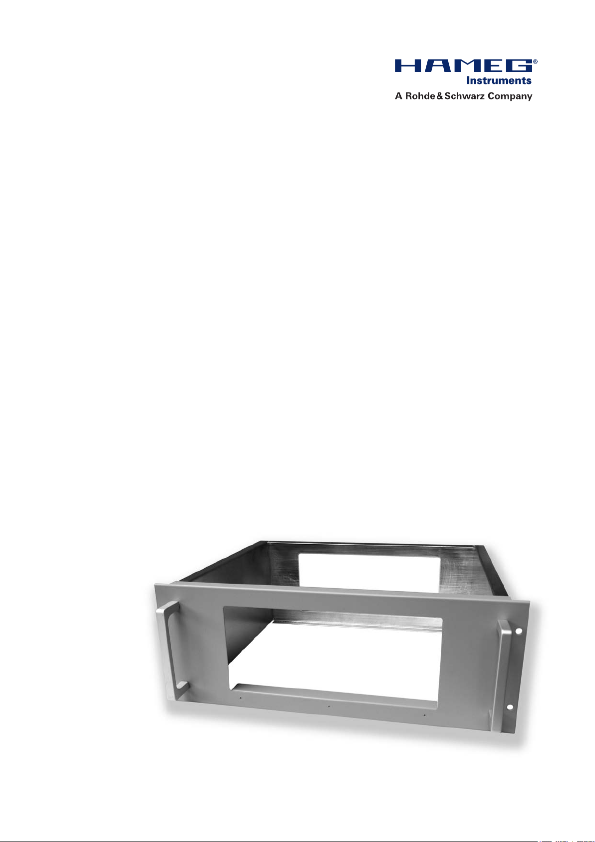
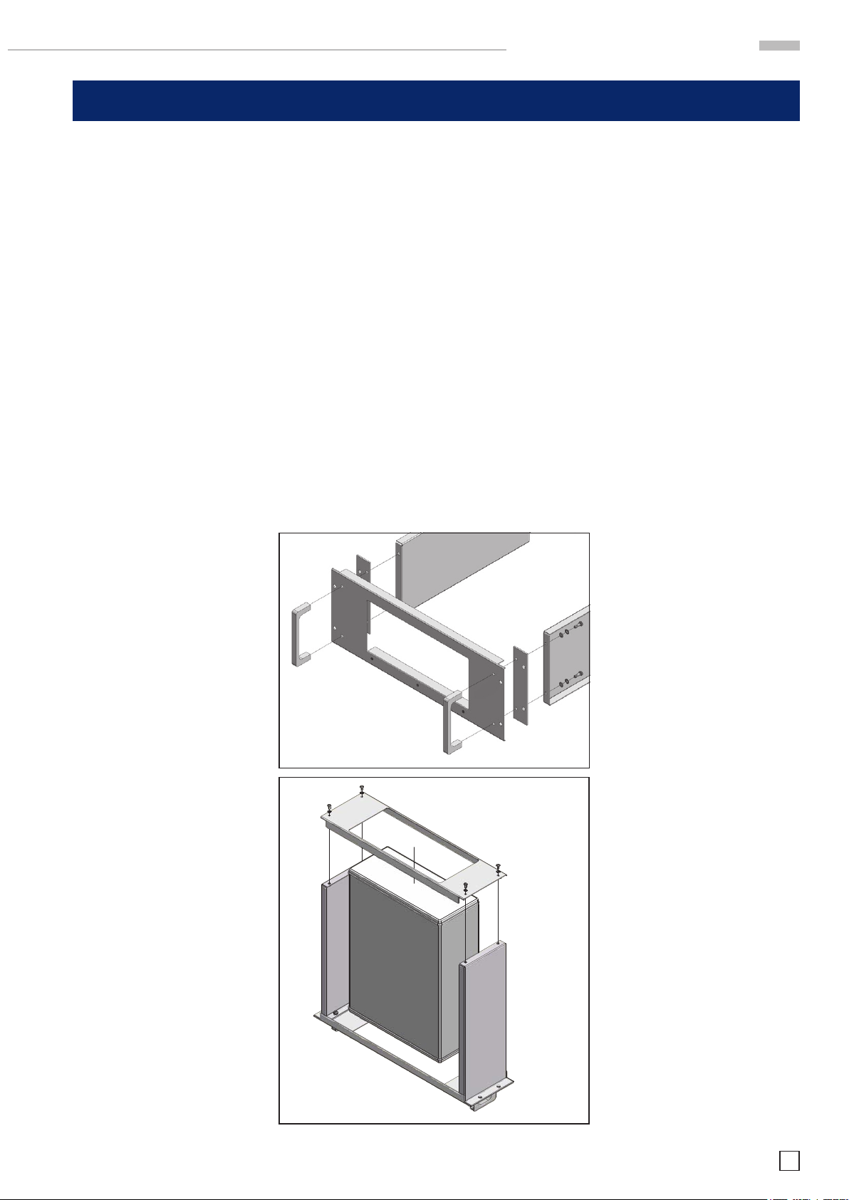
Montage
1. Fügen Sie zunächst Griffe,
Frontplatte, Distanzblech und
Seitenteile zu einem U-förmigen Rahmen zusammen
(Abb. 1).
2. Stellen Sie diesen Rahmen
mit den Griffen nach unten
senkrecht (Abb. 2).
3. Stecken Sie das Instrument mit
der Vorderseite nach unten in
die Öffnung der Frontplatte.
Abb. 1 / Fig. 1
Important:
The material contained in this document is provided “as is,”
and is subject to being changed, without notice. Further, to the
maximum extent permitted by applicable law, HAMEG disclaims
all warranties, either express or implied, with regard to this
manual and any information contained herein, including but not
limited to the implied warranties of merchantability and tness
for a particular purpose. HAMEG shall not be liable for errors
or for incidental or consequential damages in connection with
the furnishing, use, or performance of this document or of any
information contained herein.
In order to avoid overheating and unneeded heating the air
circulation must be possible through the devices. Please
reser ve enough room around the device to ensure sufcient
cooling.
ATTENTION: Shipping of an instrument built in to the rack is
not permitted.
Assembly
1. Add the handles, front panel, distance plate and the side frames
to a frame in shape of an U as
shown in Fig 1.
2. Put this frame in an upright position (see Fig. 2).
3. Add the instrument into this open
frame.
4. Close the frame with the rear
panel as shown in Fig. 2.
4. Schließen Sie den Rahmen
durch Befestigen der Rückplatte wie in Abb. 2 gezeigt.
Hinweis: Der HZP91 verfügt zusätzlich über zwei Verstärkungsschienen, die gemäß Zeichnung,
anzubringen sind (siehe Seite 9).
Abb. 2 / Fig. 2
Advice: The rackmontkit HZP91
includes 2 reinforcement racks,
which have to be xed as shown in
the picture (ref. to page 9).
Subject to change without notice
3
Page 4
1 2 3 4
A
B
C
INDEX ÄNDERUNGSBESCHREIBUNGKNZ.
Datum
01.03 A
Front-Bgr., Distanzblech, Befestigungsset, Clipbeutel
02.08.11
M o nt a g e an l e i tu n g
HZ42: 19“-Rackmount-kit
2HE / 2RU (75 mm)
Montageanleitung – HZ42 – Assembly Instructions
für / for:
HM7042-5,
HM8001-2,
Serie HM8100,
Serie HMF,
HMP2020,
HMP2030
4
3
6.3
6.4
6.5
2
1
6.7
6.6
5
6.1
6.2
6.8
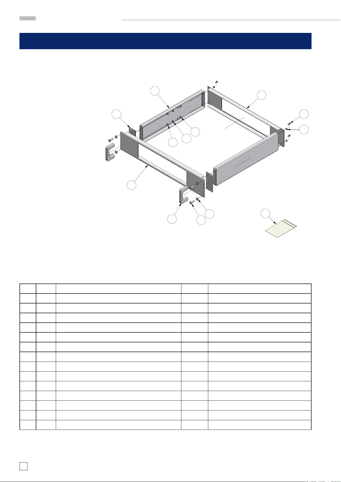
Lieferumfang: Accessories supplied
Pos. Anzahl Bezeichnung Numbers Description
1 2 LW-Griff Prolaluminium 2 Handle
2 1 Frontplatte 2HE lackiert 1 Front Panel 2RU
3 2 Distanzblech 2HE 2 Distance plate 2RU
4 2 Seitenteil mit Einpressmutter 2HE 2 Side frame 2RU
5 1 Rückplatte 2HE 1 Rear Panel 2RU
6 1 Befestigungsset (verpackt in Pos. 6.8) bestehend aus: 1 Assembly set consits of (packed in Pos. 6.8):
6.1 4 Flachkopfschraube ISO 7045 - M4x8 4 Flat headed Screw
6.2 4 Zahnscheibe DIN 6797 - A 4,3 4 Toothed lock washer
6.3 4 Flachkopfschraube ISO 7045 - M5x16 4 Flat headed Screw
6.4 4 Zahnscheibe DIN 6797 - A 5,3 4 Toothed lock washer
6.5 4 Unterlegscheibe DIN 125-1 A 5,3 4 Washer
6.6 4 Flachkopfschraube ISO 7045 - M6x16 4 Flat headed Screw
6.7 4 Unterlegscheibe DIN 125-1 A 6,4 4 Washer
6.8 1 Mini-Clipbeutel, 70x100x0,05 1 Minibag
4
Änderungen vorbehalten
Page 5

Montageanleitung – HZ43 – Assembly Instructions
1 2 3 4
A
B
C
INDEX ÄNDERUNGSBESCHREIBUNGKNZ.
Datum
01.04 A
Front Bgr., Distanzblech, Befestigungsset, Clipbeutel
02.08.11
HZ43 19“-Rackmount-kit
3HE / 3RU (125 mm)
für / for:
HM2005,
HM303-6,
HM504-2,
HM507,
HM5510,
HM5014-2,
HM5530,
HM6050-2,
HM7044
HMP4030, HMP4040
(Aus Stabilitätsgründen empfehlen
wir HZP91 für diese HMP’s, wenn
Sie aber nur 3HE Platz haben, kann
auch HZ43 eingesetzt werden.)
A ss e m b ly I n st r u c ti o n s
5
4
3
6.1
6.3
6.4
6.5
2
6.2
(we suggest HZP91 for these HMP’s
for stability reasons, but in case you
only have 3HE space you may use
HZ43)
1
6.6 6.7
Lieferumfang: Accessories supplied
Pos. Anzahl Bezeichnung Numbers Description
1 2 LW-Griff Prolaluminium 2 Handle
2 1 Frontplatte 3HE lackiert 1 Front Panel 3RU
3 2 Distanzblech 3HE 2 Distance plate 3RU
4 2 Seitenteil mit Einpressmutter 3HE 2 Side frame 3RU
5 1 Rückplatte 3HE 1 Rear Panel 3RU
6 1 Befestigungsset (verpackt in Pos. 6.8) bestehend aus: 1 Assembly set consits of (packed in Pos. 6.8):
6.1 4 Flachkopfschraube ISO 7045 - M4x8 4 Flat headed Screw
6.2 4 Zahnscheibe DIN 6797 - A 4,3 4 Toothed lock washer
6.3 4 Flachkopfschraube ISO 7045 - M5x16 4 Flat headed Screw
6.4 4 Zahnscheibe DIN 6797 - A 5,3 4 Toothed lock washer
6.5 4 Unterlegscheibe DIN 125-1 A 5,3 4 Washer
6.8
6.6 4 Flachkopfschraube ISO 7045 - M6x16 4 Flat headed Screw
6.7 4 Unterlegscheibe DIN 125-1 A 6,4 4 Washer
6.8 1 Mini-Clipbeutel, 70x100x0,05 1 Minibag
Subject to change without notice
5
Page 6

1 2 3 4
A
B
C
INDEX ÄNDERUNGSBESCHREIBUNGKNZ.
Datum
01.03 A
Front Bgr., Distanzblech, Seitenteil, Befestigungsset, Clipbeutel
02.08.11
M o nt a g e an l e i tu n g
HZ45 19“-Rackmount-kit
4HE / 4RU (175 mm)
für / for:
HM400,
HM1000,
HM1000-2,
HM1008,
HM1008-2,
HM1500,
HM1500-2,
HM1508,
HM1508-2,
HM2005-2,
HM2008
Montageanleitung – HZ45 – Assembly Instructions
4
3
5
6.1
6.2
2
1
6.6
6.7
6.5
6.3
6.4
6.8
Lieferumfang: Accessories supplied
Pos. Anzahl Bezeichnung Numbers Description
1 2 LW-Griff Prolaluminium 2 Handle
2 1 Frontplatte 4HE lackiert 1 Front Panel 4RU
3 2 Distanzblech 4HE 2 Distance plate 4RU
4 2 Seitenteil mit Einpressmutter 4HE 2 Side frame 4RU
5 1 Rückplatte 4HE 1 Rear Panel 4RU
6 1 Befestigungsset (verpackt in Pos. 6.8) bestehend aus: 1 Assembly set consits of (packed in Pos. 6.8):
6.1 4 Flachkopfschraube ISO 7045 - M4x8 4 Flat headed Screw
6.2 4 Zahnscheibe DIN 6797 - A 4,3 4 Toothed lock washer
6.3 4 Flachkopfschraube ISO 7045 - M5x16 4 Flat headed Screw
6.4 4 Zahnscheibe DIN 6797 - A 5,3 4 Toothed lock washer
6.5 4 Unterlegscheibe DIN 125-1 A 5,3 4 Washer
6.6 4 Flachkopfschraube ISO 7045 - M6x16 4 Flat headed Screw
6.7 4 Unterlegscheibe DIN 125-1 A 6,4 4 Washer
6.8 1 Mini-Clipbeutel, 70x100x0,05 1 Minibag
6
Änderungen vorbehalten
Page 7

1 2 3 4
A
B
C
INDEX ÄNDERUNGSBESCHREIBUNGKNZ.
Datum
01.03 A
Front Bgr., Distanzblech, Befestigungsset, Clipbeutel
02.08.11
A ss e m b ly I n st r u c ti o n s
Montageanleitung – HZ46 – Assembly Instructions
HZ46 19“-Rackmount-kit
4HE / 4RU (175 mm)
3
4
für / for:
series HMO 3524, 3522, 2524
and HMS1000, 1010, 3000, 3010
2
6.7
1
6.6
Lieferumfang: Accessories supplied
Pos. Anzahl Bezeichnung Numbers Description
5
6.1
6.2
6.3
6.4
6.5
6.8
1 2 LW-Griff Prolaluminium 2 Handle
2 1 Frontplatte 4HE lackiert 1 Front Panel 4RU
3 2 Distanzblech 4HE 2 Distance plate 4RU
4 2 Seitenteil mit Einpressmutter 4HE 2 Side frame 4RU
5 1 Rückplatte 4HE 1 Rear Panel 4RU
6 1 Befestigungsset (verpackt in Pos. 6.8) bestehend aus: 1 Assembly set consits of (packed in Pos. 6.8):
6.1 4 Flachkopfschraube ISO 7045 - M4x8 4 Flat headed Screw
6.2 4 Zahnscheibe DIN 6797 - A 4,3 4 Toothed lock washer
6.3 4 Flachkopfschraube ISO 7045 - M5x16 4 Flat headed Screw
6.4 4 Zahnscheibe DIN 6797 - A 5,3 4 Toothed lock washer
6.5 4 Unterlegscheibe DIN 125-1 A 5,3 4 Washer
6.6 4 Flachkopfschraube ISO 7045 - M6x16 4 Flat headed Screw
6.7 4 Unterlegscheibe DIN 125-1 A 6,4 4 Washer
6.8 1 Mini-Clipbeutel, 70x100x0,05 1 Minibag
Subject to change without notice
7
Page 8

1 2 3 4
A
B
C
INDEX ÄNDERUNGSBESCHREIBUNGKNZ.
Datum
01.01 A
Frontplatte, Distanzblech, Befestigungssatz, Clipbeutel
02.08.11
M o nt a g e an l e i tu n g
Montageanleitung – HZO91 – Assembly Instructions
HZO91 19“-Rackmount-kit
4HE / 4RU (175 mm)
für / for:
series HMO722, 724, 1022, 1024,
1522, 1524, 2022, 2024
4
3
6.6
2
5
6.1
6.2
6.3
6.4
6.5
6.8
Gehäuseschrauben vor dem Einbau entfernen
Remove housing bolts before installation
1
6.7
6.9
Lieferumfang: Accessories supplied
Pos. Anzahl Bezeichnung Numbers Description
1 2 LW-Griff Prolaluminium 2 Handle
2 1 Frontplatte 4HE lackiert 1 Front Panel 4RU
3 2 Distanzblech 4HE 2 Distance plate 4RU
4 2 Seitenteil mit Einpressmutter 4HE 2 Side frame 4RU
5 1 Rückplatte 4HE 1 Rear Panel 4RU
6 1 Befestigungsset (verpackt in Pos. 6.8) bestehend aus: 1 Assembly set consits of (packed in Pos. 6.8):
6.1 4 Flachkopfschraube ISO 7045 - M4x8 4 Flat headed Screw
6.2 4 Zahnscheibe DIN 6797 - A 4,3 4 Toothed lock washer
6.3 4 Flachkopfschraube ISO 7045 - M5x16 4 Flat headed Screw
6.4 4 Zahnscheibe DIN 6797 - A 5,3 4 Toothed lock washer
6.5 4 Unterlegscheibe DIN 125-1 A 5,3 4 Washer
6.6 2 PEM Einpressschraube SCBJ-M3-12 2 Spinning clinch bolt
6.7 4 Flachkopfschraube ISO 7045 - M6x16 4 Flat headed Screw
6.8 4 Unterlegscheibe DIN 125-1 A 6,4 4 Washer
6.9 1 Mini-Clipbeutel, 70x100x0,05 1 Minibag
8
Änderungen vorbehalten
Page 9

A ss e m b ly I n st r u c ti o n s
1 2 3 4
A
B
C
INDEX ÄNDERUNGSBESCHREIBUNGKNZ.
Datum
01.00
-
neu erstellt
17.06.11
Montageanleitung – HZP91 – Assembly Instructions
HZP91 19“-Rackmount-kit
6
4HE / 4RU (175 mm)
für / for:
HMP4030 and HMP4040
6
Hinweis: Der HZP91 verfügt zusätzlich über zwei Verstärkungsschienen (6), die gemäß Zeichnung, anzubringen sind.
12
7.4 7.3
Advice: The rackmontkit HZP91 includes 2 reinforcement racks
(6), which have to be xed as shown in the picture.
Lieferumfang: Accessories supplied
Pos. Anzahl Bezeichnung Numbers Description
5
7.1
7.7
7.7
7.1
7.2
4
7.5
3
7.6
7.8
1 2 LW-Griff Prolaluminium 2 Handle
2 1 Frontplatte 4HE gebogen, lackiert 1 Front Panel 4RU
3 2 Distanzblech 4HE 2 Distance plate 4RU
4 2 Seitenteil 4HE 2 Side frame 4RU
5 1 Rückplatte gebogen 4HE 1 Rear Panel 4RU
6 2 Verstärkungsschiene 2 reinforcement rack
7 1 Befestigungsset (verpackt in Pos. 7.8) bestehend aus: 1 Assembly set consits of (packed in Pos. 6.8):
7.1 14 Flachkopfschraube ISO 7045 - M4x8 14 Flat headed Screw
7.2 4 Flachkopfschraube ISO 7045 - M5x16 4 Flat headed Screw
7.3 4 Unterlegscheibe DIN 125-1 A 6,4 4 Washer
7.4 4 Flachkopfschraube ISO 7045 - M6x16 4 Flat headed Screw
7.5 4 Zahnscheibe DIN 6797 - A 5,3 4 Toothed lock washer
7.6 4 Unterlegscheibe DIN 125-1 A 5,3 4 Washer
7.7 14 Zahnscheibe DIN 6797 - A 4,3 14 Toothed lock washer
7.8 1 Mini-Clipbeutel, 70x100x0,05 1 Minibag
Subject to change without notice
9
Page 10

M o nt a g e an l e i tu n g
Different Perspectives
Front View HZ42/43
Bottom View HZ45
Rear View HZ42/43
Side View (right)
Side View HZ46
Top View
Rear View HZ46
10
Änderungen vorbehalten
Page 11

A ss e m b ly I n st r u c ti o n s
Subject to change without notice
11
Page 12
Oscilloscopes
Spectrum Analyzer
Power Supplies
Modular System
Series 8000
Programmable Instruments
Series 8100
authorized dealer
*47-4243-4510*
47-4243-4510
w w w . h a m e g . c o m
Subject to change without notice HAMEG Instruments GmbH
47-4243-4510 (2) 01122011 Industriestraße 6
© HAMEG Instruments GmbH D-63533 Mainhausen
A Rohde & Schwarz Company Tel +49 (0) 61 82 800-0
DQS-Zertikation: DIN EN ISO 9001:2000 Fax +49 (0) 61 82 800-100
Reg.-Nr.: 071040 QM sales@hameg.de
 Loading...