

Page 1
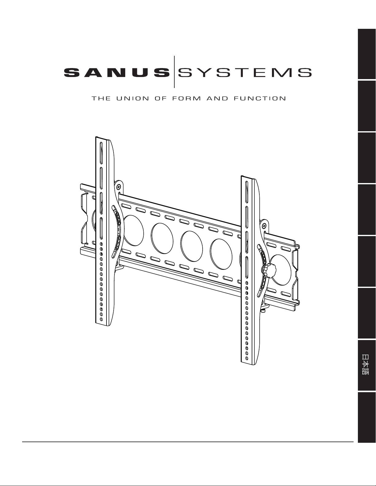
International Assembly Instructions for model VMPL50
ENGLISH
ESPAÑOL DEUTSCH FRANÇAIS ITALIANO PYCCKO
Spanish German French Italian Russian Japanese Mandarin
Sanus Systems 2221 Hwy 36 West, Saint Paul, MN 55113 7.05.05
Customer Service: (800) 359-5520 • (651) 484-7988 • fax (651) 636-0367
Customer Service Europe: 31 (0)20 5708938 • fax 31 (0)20 5708989
See complementary Sanus products at www.sanus.com
中文
Page 2

Page 3
Assembly Instructions for model: VMPL50
Thank you for choosing a VisionMount™ wall mount. This product is designed to mount at panel televisions weighing up to 130 lb. to a vertical wall.
It allows you to tilt your new television up to 12º without the use of tools.
Safety Warning: If you do not understand these directions, or have any doubts about the safety of the installation, please call a qualied contractor
or contact Sanus at 800.359.5520 or www.sanus.com. We can quickly assist you with installation questions and missing or damaged parts. Replacement parts for Sanus products purchased through authorized dealers will be shipped directly to you. Check carefully to make sure there are no missing
or defective parts. Never use defective parts. Improper installation may cause damage or serious injury. Do not use this product for any purpose that
is not explicitly specied by Sanus Systems. Sanus Systems can not be liable for damage or injury caused by incorrect mounting, incorrect assembly,
or incorrect use. Note: The supplied hardware is not for steel stud walls or old cinder block walls. If you are uncertain about the nature of your wall,
consult an installation contractor.
Required Tools: 3/16 drill bit, 1/2” Masonry Bit for brick concrete or concrete block installations, 1/2” wrench or socket, Phillips screw driver.
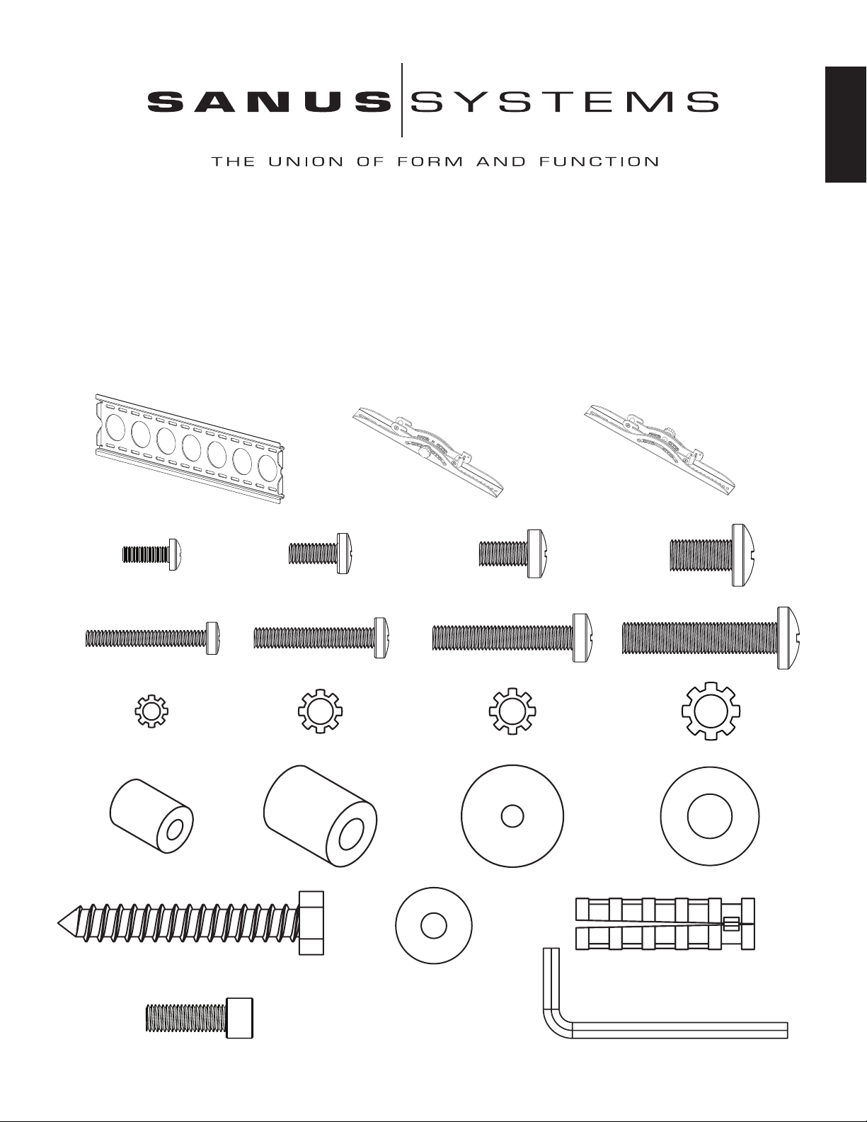
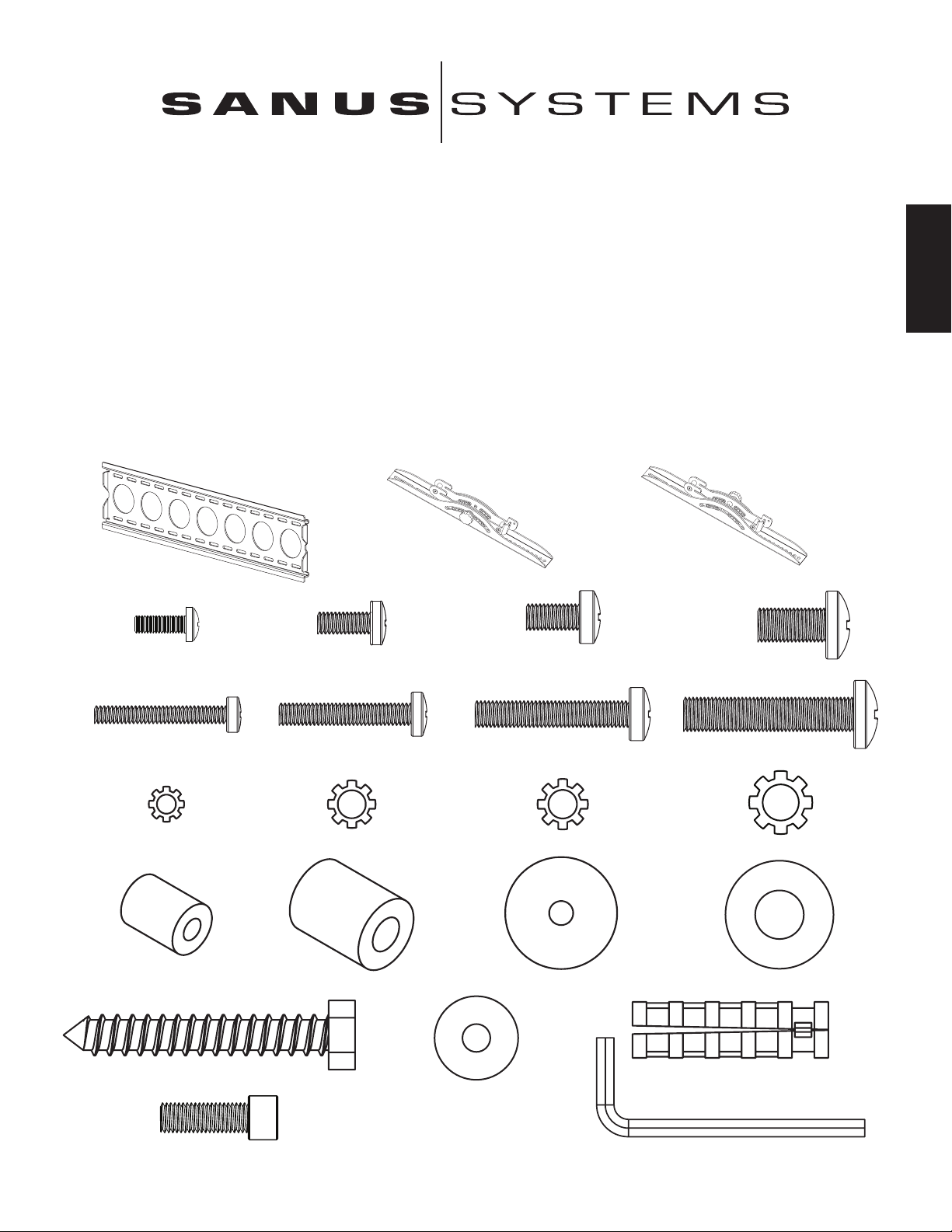
Supplied Parts: *Not shown as actual size.
ENGLISH
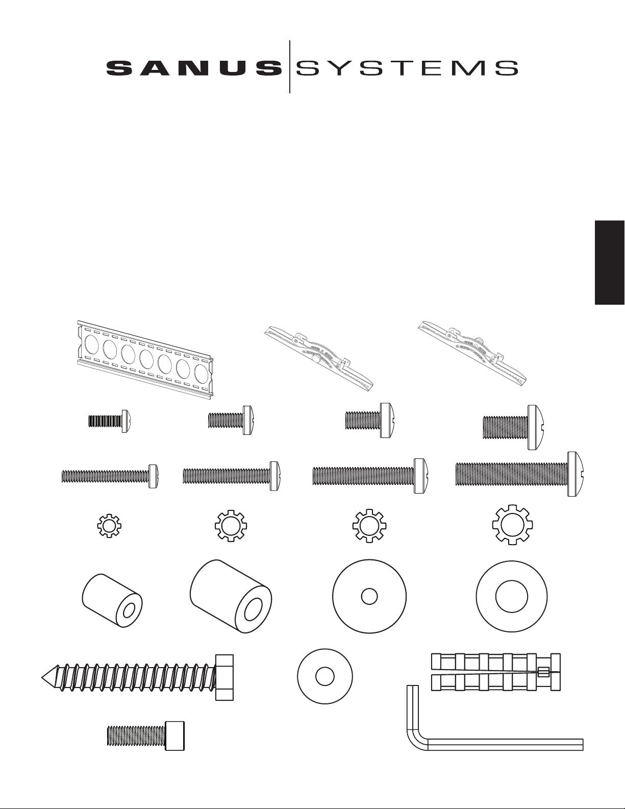
(1) Wall Plate - a* (1) Left Monitor Bracket - b* (1) Right Monitor Bracket - c*
(4) M4 x 12 Bolt - d (4) M5 x 12 Bolt - e (4) M6 x 12 Bolt - f (4) M8 x 16 Bolt - g
(4) M4 x 30 Bolt - h (4) M5 x 30 Bolt - i (4) M6 x 35 Bolt - j (4) M8 x 40 Bolt - k
(4) M4 Lock Washer - l (4) M5 Lock Washer - m (4) M6 Lock Washer - n (4) M8 Lock Washer - o
(4) M4/M5 Spacer - p (4) M6/M8 Spacer - q (8) M4/M5 Washer - r (4) M6/M8 Washer - s
(6) Lag Bolt - t (6) Lag Bolt Washer - u (6) Concrete Anchor - v
(2) Safety Bolt - w (1) Allen Key - x*
Page 4
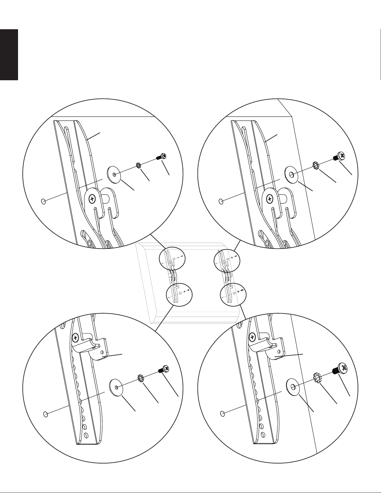
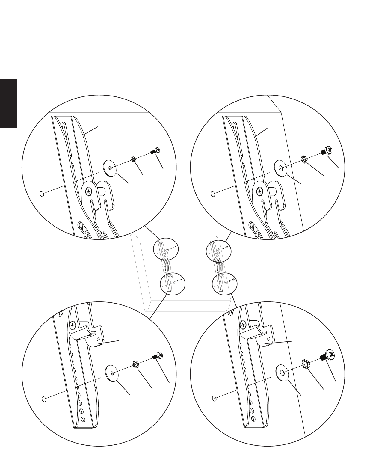
Step 1: Mount Monitor Brackets to a television with a at back
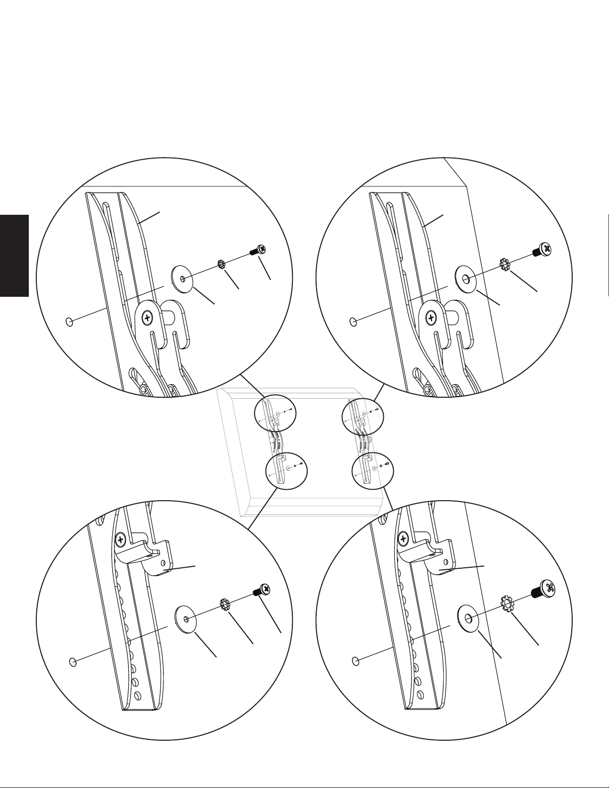
First, determine the diameter of the Bolt (d,e,f,g) your TV requires by hand threading them into the threaded insert on the back of the
TV. If you encounter any resistance stop immediately! Once you have determined the correct diameter, see the appropriate Diagram below. You will thread the Bolt through the appropriate Lock Washer (l,m,n,o), the corresponding Washer (r,s), the Monitor Bracket (b,c),
and nally into the TV. Make sure the Monitor Brackets are vertically centered and level with each other. See the appropriate Diagram
below.
ENGLISH
Note: For televisions with a curved back, or an obstruction near the threaded insert see Step 2.
M4 Diameter Bolt M6 Diameter Bolt
b c
d f
l n
r s
Diagram 1
M5 Diameter Bolt M8 Diameter Bolt
b c
e g
m o
r s
Note: After completing Step 1, proceed to Step 3.
Page 5
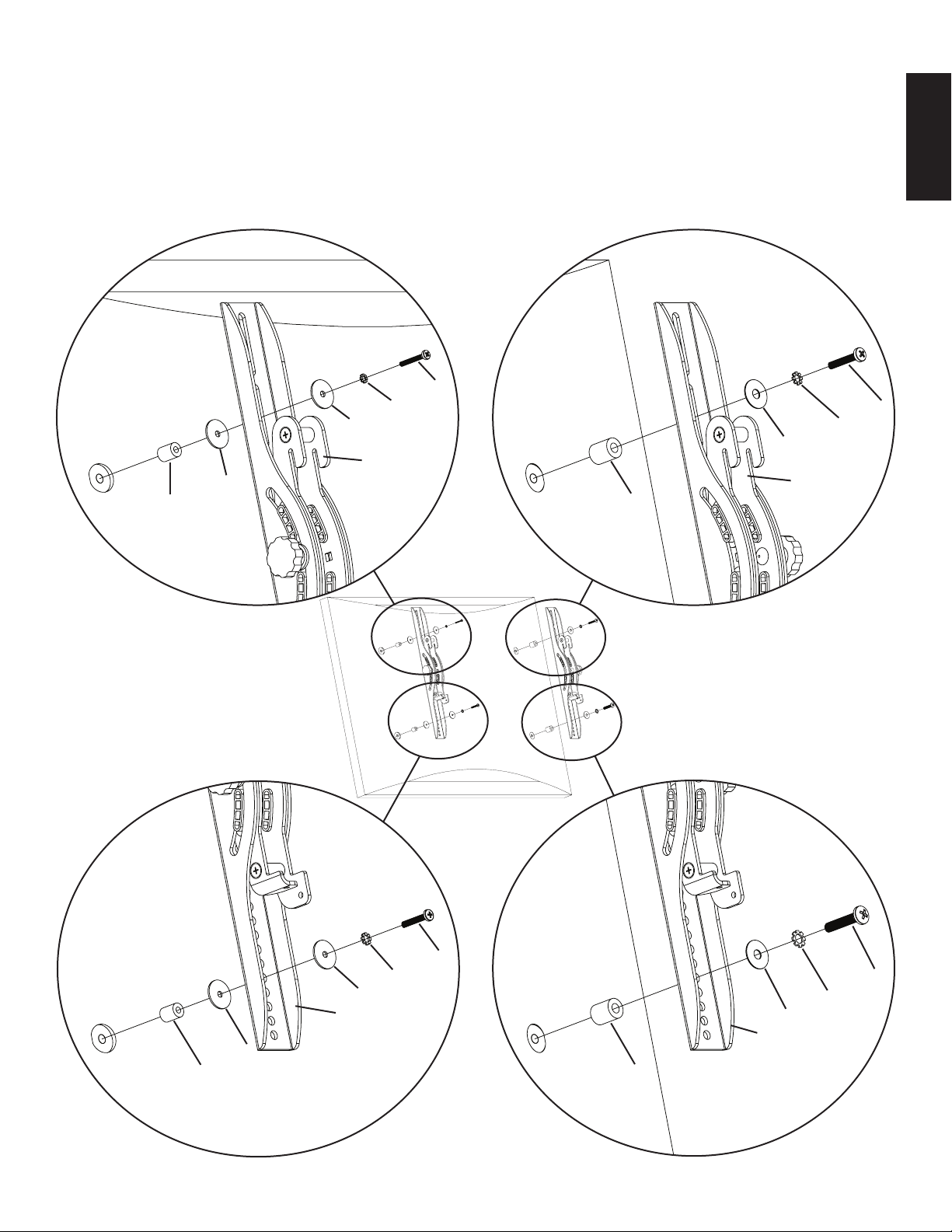
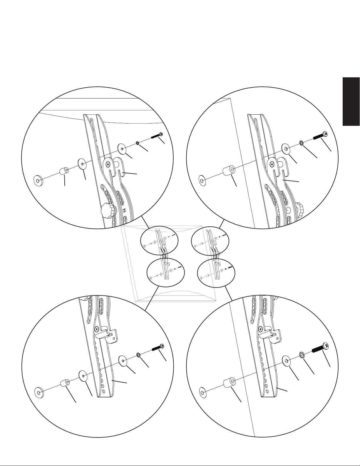
Step 2: Mount Monitor Brackets to a television with a curved back or an obstruction near the threaded insert
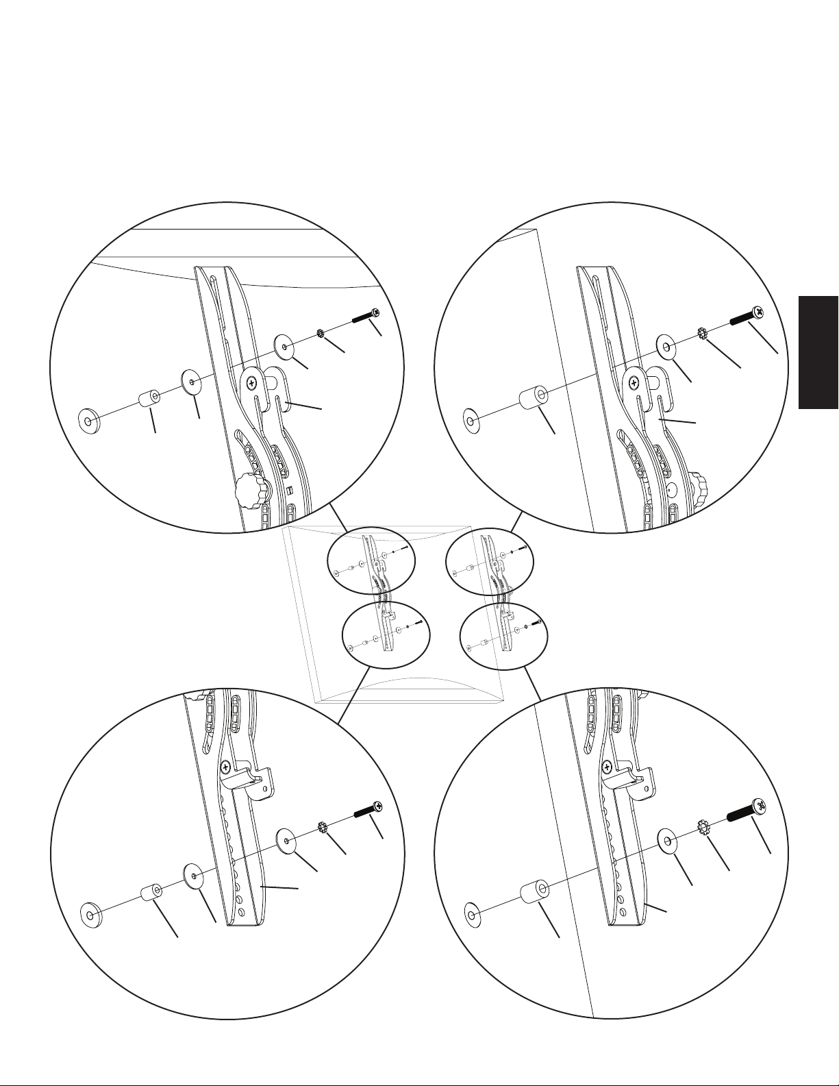
First, determine the diameter of the Bolt (h,i,j,k) your TV requires by hand threading them into the threaded insert on the back of the TV.
If you encounter any resistance stop immediately! Once you have determined the correct diameter, see the appropriate Diagram below.
You will thread the Bolt through the appropriate Lock Washer (l,m,n,o), the corresponding Washer (r,s), the Monitor Bracket (b,c), a
Spacer (p,q), a second Washer (r - M4/M5 diameter only) and nally into the TV. Make sure the Monitor Brackets are vertically centered
and level with each other. See the appropriate Diagram below.
M4 Diameter Bolt M6 Diameter Bolt
h
l j
r n
s
b
r c
p q
ENGLISH
Diagram 2
M5 Diameter Bolt M8 Diameter Bolt
i
m k
r o
b s
c
r
p q
Page 6
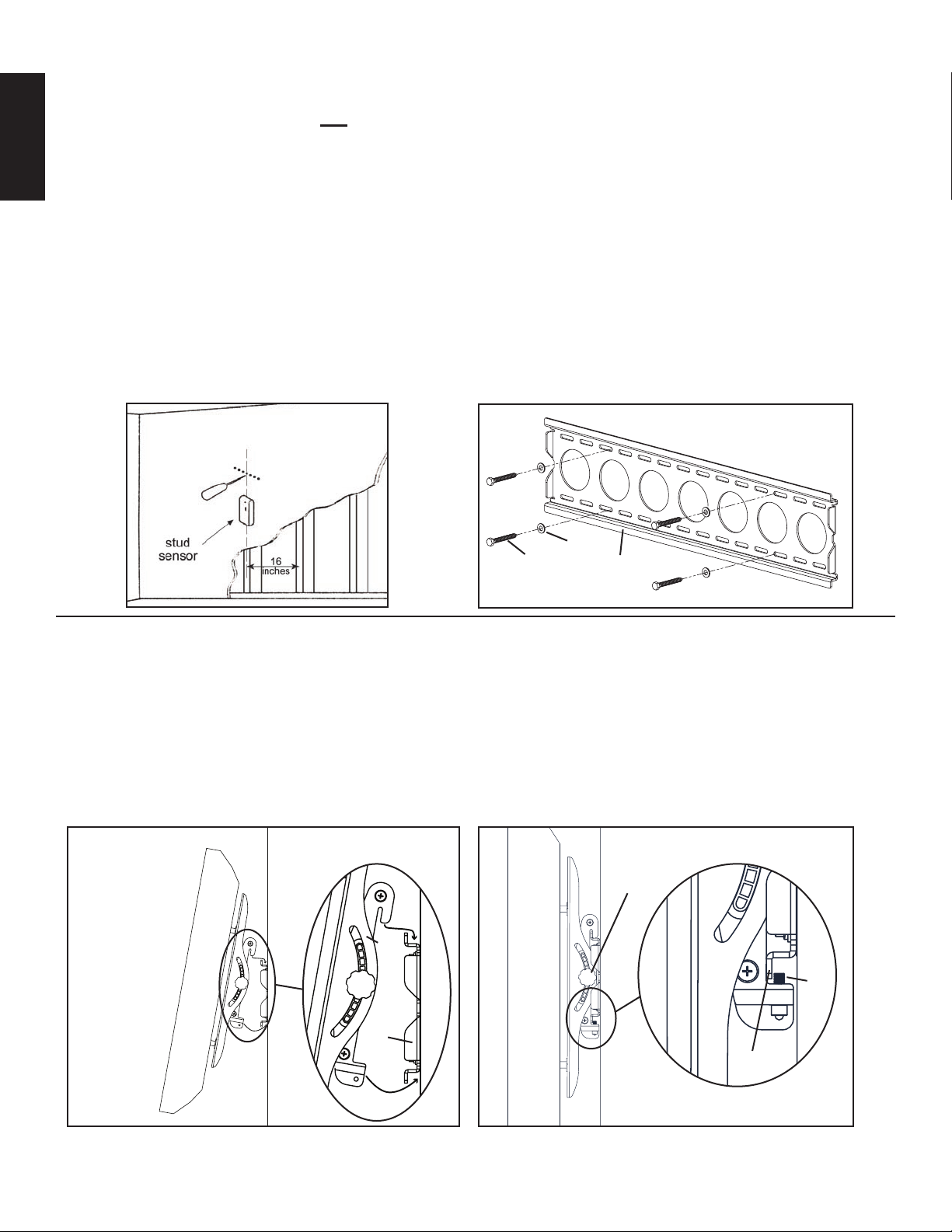
Step 3: Mounting the Wall Plate: Wood Stud, Brick, Solid Concrete, and Concrete Block mounting options are provided.
Wood Stud mounting:
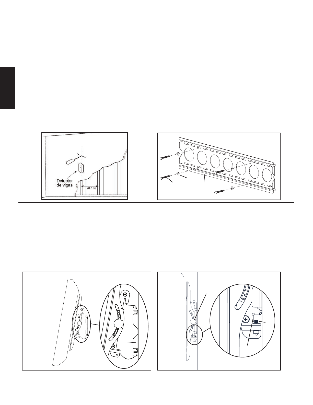
The Wall Plate (a) must be mounted to two wood studs at least 12" apart. Use a high quality stud sensor to locate two adjacent
studs. It is a good idea to verify where the studs are located with an awl or thin nail shown in Diagram 3a. Pre-drill a 2.5" deep hole at
the desired height in each stud using a 3/16" drill bit. Make sure these holes are in the center area of the studs and level with each other.
Use the Wall Plate as a template to mark the location of the second hole in each stud. Drill 2.5" deep holes using the 3/16" drill bit in the
ENGLISH
marked location. Attach the Wall Plate to the wall using the four Lag Bolts (t) and four Lag Bolt Washers (u). Make sure the Wall Plate
is oriented so the at surface in the center of the plate is against the wall and that a set of Lag Bolts is on each side of the center of the
Wall Plate as shown in Diagram 3b.
Brick, Solid Concrete and Concrete Block mounting:
Use the Wall Plate (a) as a template to mark 6 hole locations on the wall. Locate the outer holes as far to the outer edges of the wall
plate as possible. Three in the top row of slots and three more in the bottom row. Make sure these holes are level and there is at least 6"
between any two holes. Pre-Drill these holes with a 1/2" masonry bit to at least 2.5" in depth. Insert a Concrete Anchor (v) into each of
these holes. Make sure the anchor is seated completely ush with the concrete surface even if there is a layer of drywall or other material
in front. Attach the Wall Plate to the wall using six Lag Bolts (t) and six Lag Bolt Washers (u).
Diagram 3a Diagram 3b
u
t a
Step 4: Attaching Monitor to Wall Plate and adding Safety Bolts
Warning: Some televisions may require 2 people to lift! Sanus is not responsible for personal injury or product
damage.
Hang the TV onto the Wall Plate: First hook the Monitor Brackets (b,c) over the top of the Wall Plate (a), then let the bottom of the
Monitor Brackets rotate in under the bottom of the Wall Plate as shown in diagram 4a. Insert the Safety Bolts (w) into the threaded holes
in the bottom of the Monitor Brackets and tighten them with the Allen Key (x) so that they sit behind the bottom tab on the Wall Plate
as shown in diagram 4b. Finally set the tension of the knobs on the Monitor Brackets and you are free to adjust your new at panel TV.
Diagram 4a Diagram 4b
knob
b,c
w
a
bottom
tab
Page 7
Instrucciones de armado del modelo: VMPL50
L A U N I Ó N D E F O R M A Y F U N C I Ó N
Gracias por elegir el soporte de pared VisionMount™. Este producto ha sido diseñado para montar televisores con pantalla plana con un peso de hasta
59 kg en una pared vertical. Este modelo permite inclinar el televisor hasta 12° sin el uso de herramientas.
Advertencia de seguridad: Si no entiende estas instrucciones o si tiene alguna duda con respecto a la seguridad de la instalación, llame a un
contratista calicado o llámenos al 800.359.5520 (en EE.UU.) o al 31 (0) 20 5708938 (en Europa). También nos puede visitar en nuestro sitio
www.sanus.com. Podemos ayudarle rápidamente a responder sus preguntas sobre la instalación o con respecto a las piezas faltantes o dañadas. Las
piezas de repuesto para los productos Sanus comprados a través de un distribuidor autorizado se enviarán directamente a usted. Revise cuidadosamente
para asegurarse de que no hayan piezas faltantes ni defectuosas. Nunca use piezas que presenten algún defecto. La instalación incorrecta puede provocar
daño o lesiones graves. No use este producto para nes que no estén especicados explícitamente por Sanus Systems. Sanus Systems no se hace
responsable de los daños ni de las lesiones causadas por el montaje, armado o uso incorrectos. Nota: La tornillería suministrada no es para paredes con
pies derechos de acero ni para paredes con bloques de cemento. Si se tiene alguna duda sobre la naturaleza de la pared, consultar con un contratista.
Herramientas necesarias: Broca de 3/16 pulgada, broca para concreto de 1/2 pulgada para instalaciones sobre ladrillo, concreto o bloques de
hormigón, llave mecánica o casquillo de 1/2 pulgada, destornillador Phillips.
Piezas suministradas: *No es el tamaño real.
(1) Placa adaptadora - a* (1) Soporte izquierdo de monitor - b* (1) Soporte derecho de monitor - c*
(4) Perno M4 x 12 - d (4) Perno M5 x 12 - e (4) Perno M6 x 12 - f (4) Perno M8 x 16 - g
ESPAÑOL
(4) Perno M4 x 30 - h (4) Perno M5 x 30 - i (4) Perno M6 x 35 - j (4) Perno M8 x 40 - k
(4) Arandela de seguridad M4 - l (4) Arandela de seguridad M5 - m (4) Arandela de seguridad M6 - n (4) Arandela de seguridad M8 - o
(4) Espaciador M4/M5 - p (4) Espaciador M6/M8 - q (8) Arandela M4/M5 - r (4) Arandela M6/M8 - s
(6) Tirafondo - t (6) Anclaje para concreto - v
(6) Arandela de tirafondo - u
(2) Perno de seguridad - w (1) Llave allen - x*
Page 8
Paso 1: Montar los soportes de monitor a un televisor con la parte trasera plana
Primero, determinar el diámetro del perno (d, e, f, g) que necesita el televisor. Para ello enroscar los pernos en el inserto roscado que se encuentra en
la parte trasera del televisor. ¡Si se encuentra alguna resistencia, parar inmediatamente! Una vez que se haya determinado el diámetro correcto, ver el
diagrama pertinente más abajo. Pasar el perno por la arandela de seguridad correcta (l, m, n, o), la arandela correspondiente (r, s), el soporte de monitor
(b, c) y nalmente insertarlo en el televisor. Asegurarse de que los soportes de monitor queden centrados verticalmente y nivelados entre ellos. Ver el
diagrama pertinente más abajo.
Nota: Para los televisores con la parte trasera curvada o con una obstrucción cerca del inserto roscado, ver el paso 2.
Perno de diámetro M4 Perno de diámetro M6
ESPAÑOL
b c
d f
l n
r s
Diagrama 1
Perno de diámetro M5 Perno de diámetro M8
b c
e g
m o
r s
Nota: Después de completar el paso 1, proceder al paso 3.
Page 9
Paso 2: Montaje de soportes de monitor a un televisor con la parte trasera curvada o con una obstrucción cerca del inserto roscado
Primero, determinar el diámetro del perno (h, i, j, k) que necesita el televisor. Para ello enroscar los pernos en el inserto roscado que se encuentra en
la parte trasera del televisor. ¡Si se encuentra alguna resistencia, parar inmediatamente! Una vez que se haya determinado el diámetro correcto, ver el
diagrama pertinente más abajo. Pasar el perno por la arandela de seguridad correcta (l, m, n, o), la arandela correspondiente (r, s), el soporte de monitor
(b, c), un espaciador (p, q), una segunda arandela (r - diámetro M4/M5 solamente) y nalmente insertarlo en el televisor. Asegurarse de que los soportes
de monitor queden centrados verticalmente y nivelados entre ellos. Ver el diagrama pertinente más abajo.
Perno de diámetro M4 Perno de diámetro M6
h
l j
r n
s
b
r c
p q
ESPAÑOL
Diagrama 2
Perno de diámetro M5 Perno de diámetro M8
i
m k
r o
b s
c
r
p q
Page 10
Paso 3: Montaje de la placa de pared: Se proporcionan opciones para montaje sobre pie derecho de madera, ladrillo, concreto sólido
y bloque de hormigón.
Montaje sobre pie derecho de madera:
La placa de pared (a) se debe montar sobre dos pies derechos separados al menos por 30,5 cm. Utilizar un detector de vigas de alta
calidad para localizar dos pies derechos adyacentes. Es una buena idea vericar la ubicación de los pies derechos con un punzón o clavo delgado,
como se ilustra en el diagrama 3a. Perforar con antelación un agujero profundo de 6,4 cm en la altura deseada de cada pie derecho utilizando una broca
de 3/16 pulgada. Asegurarse que estos agujeros queden en el centro de los pies derechos y nivelados entre ellos. Utilizar la placa de pared como una
plantilla para marcar la posición del segundo agujero en cada pie derecho. Perforar agujeros de 6,4 cm con una broca de 3/16 pulgada en la ubicación
marcada. Conectar la placa en la pared utilizando los cuatro tirafondos (t) y las cuatro arandelas de tirafondo (u). Asegurarse que la placa de pared
quede orientada de manera que la supercie plana quede contra la pared y que los tirafondos se encuentren en el centro de cada lado de la placa de
pared, como se ilustra en el diagrama 3b.
Montaje en ladrillo, concreto y bloque de hormigón:
Utilizar la placa de pared (a) como una plantilla para marcar las 6 posiciones de los agujeros en la pared. Ubicar los agujeros externos lo más apegado
posible a los bordes externos de la placa de pared. Tres en la hilera superior de ranuras y tres más en la hilera inferior. Asegurarse de que estos agujeros
estén nivelados y que haya una separación de al menos 15,2 cm entre ellos. Perforar cuidadosamente estos agujeros con una broca para concreto de
ESPAÑOL
1/2 pulgada a una profundidad mínima de 6,4 cm. Insertar un anclaje para concreto (v) en cada uno de estos agujeros. Asegurarse de que el anclaje
quede asentado completamente a ras con la supercie de concreto, incluso si hubiera una capa de yeso o de otro material encima. Conectar la placa en
la pared utilizando los seis tirafondos (t) y las seis arandelas de tirafondo (u).
Diagrama 3a Diagrama 3b
u
t a
Paso 4: Conexión del monitor a la placa de pared y agregado de los pernos de seguridad
Advertencia: ¡Se requieren dos personas para levantar algunos televisores! Sanus no es responsable por lesiones personales
ni daño al producto.
Colgar el televisor en la placa de pared: Primero enganchar los soportes de monitor (b, c) en la parte superior de la placa de pared (a), luego dejar que la
base de los soportes de monitor giren debajo de la placa de pared, como se ilustra en el diagrama 4a. Insertar los pernos de seguridad (w) en los agujeros
roscados que se encuentran en la base de los soportes de monitor y apretarlos con una llave allen (x), de manera que se asienten detrás de la lengüeta
inferior del soporte de pared, como se ilustra en el diagrama 4b. Finalmente ajustar la tensión de las perillas en los soportes de monitor y se podrá ajustar
libremente el televisor de pantalla plana.
Diagrama 4a Diagrama 4b
perilla
b,c
w
a
pestaña
inferior
Page 11
Montageanweisungen für das Modell: VMPL50
D I E E I N H E I T V O N F O R M U N D F U N K T I O N
Wir freuen uns, dass Sie sich für eine VisionMount™-Wandhalterung von Sanus Systems entschieden haben. Das Produkt ist für die Montage von
Flachbildfernsehern mit einem Gewicht von maximal 59 kg an einer vertikalen Wand vorgesehen. Der neue Fernseher kann ohne Verwendung von
Werkzeugen mühelos bis zu 12° nach oben und unten geneigt werden.
Sicherheitshinweis: Wenn Sie diese Anweisungen nicht verstehen oder Zweifel an der Sicherheit der Montage haben, rufen Sie einen Fachmann
an oder kontaktieren Sie Sanus Systems telefonisch unter +1-800-359-5520 (USA) oder +31-(0)20-570-8938 (Europa). Oder besuchen Sie uns im
Internet unter www.sanus.com. Wir können Ihnen bei Fragen zur Montage und zu beschädigten oder fehlenden Teilen schnell helfen. Ersatzteile für
bei autorisierten Fachhändlern gekaufte Sanus-Produkte werden direkt an Ihre Adresse versendet. Es dürfen keine Bauteile fehlen oder defekt sein.
Verwenden Sie niemals beschädigte Teile! Unsachgemäße Montage kann Schäden am Gerät und schwere Verletzungen hervorrufen! Verwenden Sie
das Produkt nicht für andere als von Sanus Systems explizit genannte Zwecke. Sanus Systems haftet nicht für Schäden oder Verletzungen, die durch
unsachgemäße Montage, fehlerhaften Zusammenbau oder unsachgemäße Nutzung entstehen. Hinweis: Das mitgelieferte Montagezubehör eignet
sich nicht für Trockenwände mit Stahlträgern oder Wände aus Holzblocksteinen. Bei Zweifeln an der Bauweise Ihrer Wand wenden Sie sich an einen
Experten.
Erforderliche Werkzeuge: Bohrer 3/16 Zoll, Steinbohrer 1/2 Zoll für Ziegel, Beton oder Betonsteine, Maulschlüssel- oder Steckschlüsselsatz
1/2 Zoll, Kreuzschlitzschraubendreher
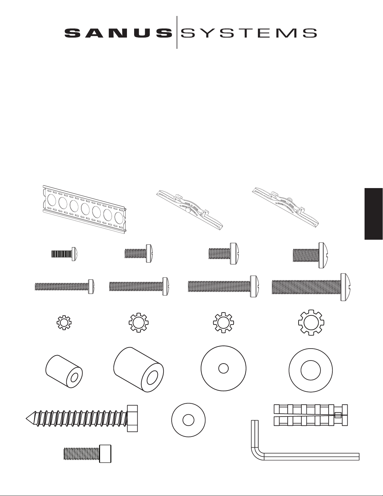
Mitgelieferte Teile: Mit * markierte Teile sind verkleinert dargestellt.
(1) Wandplatte – a* (1) Linke Monitorklammer – b* (1) Rechte Monitorklammer – c*
DEUTSCH
(4) Schraube M4 x 12 – d (4) Schraube M5 x 12 – e (4) Schraube M6 x 12 – f (4) Schraube M8 x 16 – g
(4) Schraube M4 x 30 – h (4) Schraube M5 x 30 – i (4) Schraube M6 x 35 – j (4) Schraube M8 x 40 – k
(4) Sicherungsscheibe M4 – l (4) Sicherungsscheibe M5 – m (4) Sicherungsscheibe M6 – n (4) Sicherungsscheibe M4 – o
(4) Distanzstück M4/M5 – p (4) Distanzstück M6/M8 – q (8) Unterlegscheibe M4/M5 – r (4) Unterlegscheibe M6/M8 – s
(6) Holzschraube – t (6) Betondübel – v
(6) Holzschraubenunterlegscheibe – u
(2) Sicherungsschraube – w (1) Inbusschlüssel – x*
Page 12
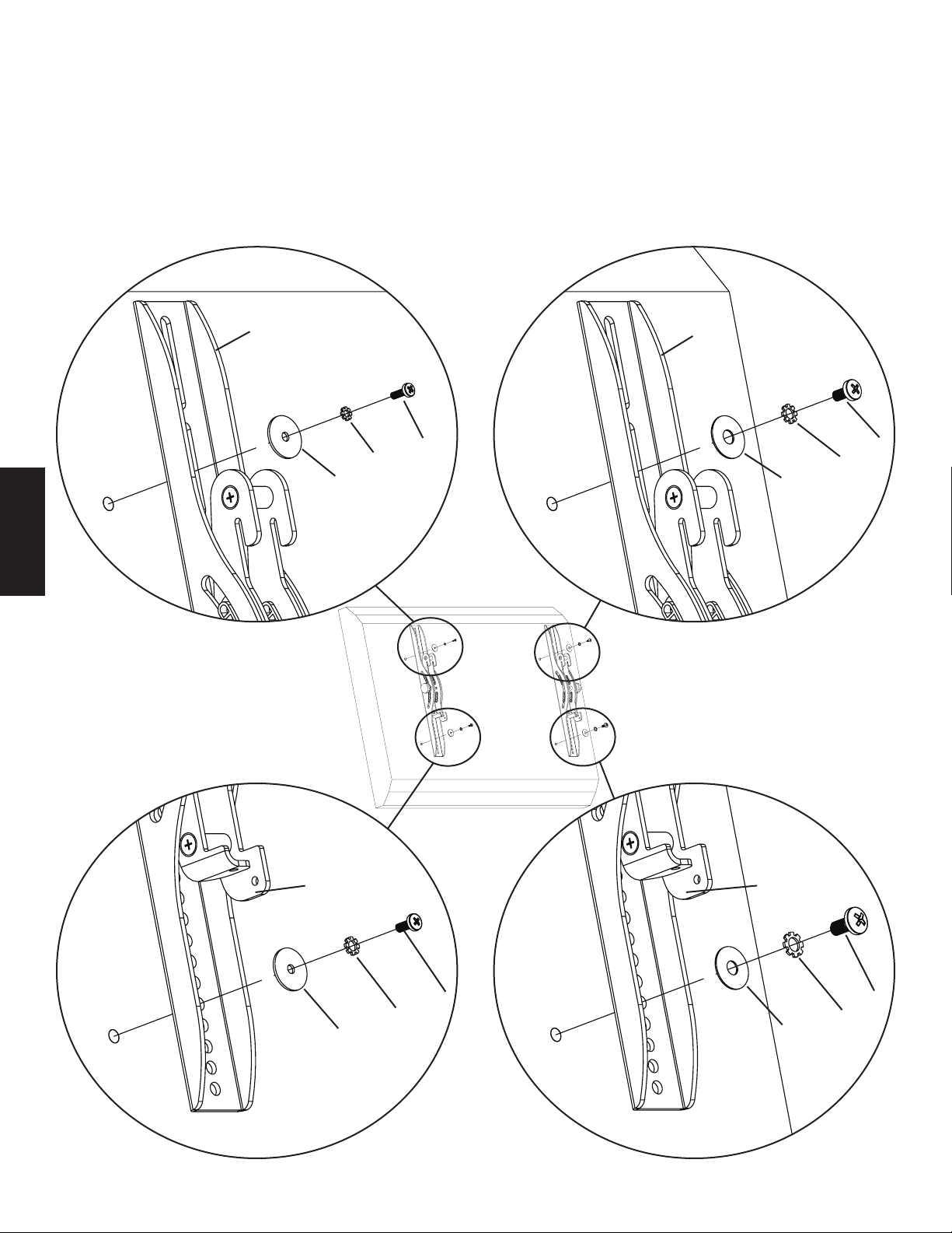
Schritt 1: Montage der Monitorklammern an einem Fernseher mit acher Rückseite
Zunächst die erforderliche Schraubengröße (d, e, f, g) für den Fernseher durch probeweises Eindrehen der Schrauben in die Aussparung für die
Gewindeeinsätze an der Rückseite des Fernsehers bestimmen. Wenn ein Widerstand zu spüren ist, sofort aufhören! Sobald der korrekte Durchmesser
ermittelt ist, die entsprechende unten stehende Abbildung beachten. Eine Schraube durch die entsprechende Sicherungsscheibe (l, m, n, o), die
dazugehörige Unterlegscheibe (r, s) und die Monitorklammer (b, c) stecken und in den Fernseher eindrehen. Die Monitorklammern müssen vertikal
mittig und aufeinander ausgerichtet sein. Die entsprechende unten stehende Abbildung beachten.
Hinweis: Informationen zu Fernsehern mit einer gekrümmten Rückseite oder einem Hindernis an der Aussparung für die
Gewindeeinsätze nden Sie in Schritt 2.
Schraube M4 Schraube M6
b c
DEUTSCH
d f
l n
r s
Abbildung 1
Schraube M5 Schraube M8
b c
e g
m o
r s
Hinweis: Nach Schritt 1 mit Schritt 3 fortfahren.
Page 13
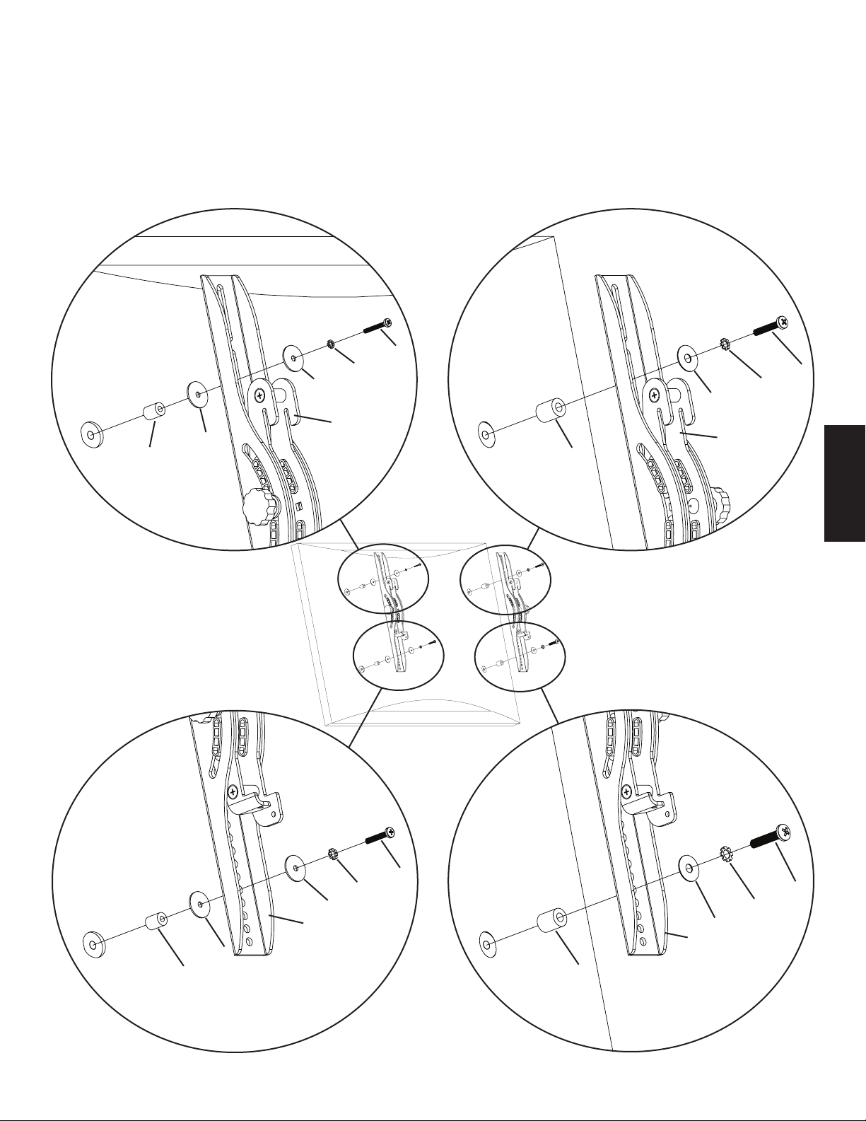
Schritt 2: Montage der Monitorklammern für einen Fernseher mit einer gekrümmten Rückseite oder einem Hindernis an der
Aussparung für die Gewindeeinsätze
Zunächst die erforderliche Schraubengröße (h, i, j, k) für den Fernseher durch probeweises Eindrehen der Schrauben in die Aussparung für die
Gewindeeinsätze an der Rückseite des Fernsehers bestimmen. Wenn ein Widerstand zu spüren ist, sofort aufhören! Sobald der korrekte Durchmesser
ermittelt ist, die entsprechende unten stehende Abbildung beachten. Eine Schraube durch die entsprechende Sicherungsscheibe (l, m, n, o), die dazugehörige
Unterlegscheibe (r, s), die Monitorklammer (b, c), ein Distanzstück (p, q), eine zweite Unterlegscheibe (r – nur M4/M5) und in den Fernseher eindrehen.
Die Monitorklammern müssen vertikal mittig und aufeinander ausgerichtet sein. Die entsprechende unten stehende Abbildung beachten.
Schraube M4 Schraube M6
h
l j
r n
s
b
r c
p q
Abbildung 2
Schraube M5 Schraube M8
DEUTSCH
i
m k
r o
b s
c
r
p q
Page 14
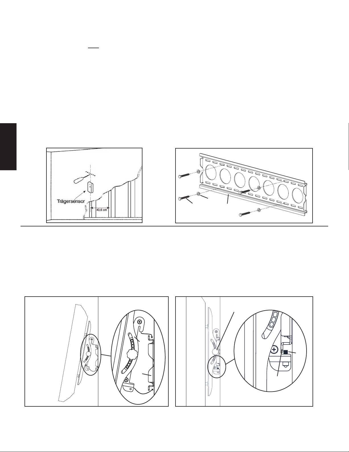
Schritt 3: Montage der Wandplatte: Es wird Zubehör zur Montage an Holzbalkenträgern, Ziegelwänden, Massivbeton und Betonsteinen
mitgeliefert.
Montage an einem Holzbalkenträger:
Die Wandplatte (a) muss an zwei Holzbalkenträgern mit einem Mindestabstand von 30,5 cm angebracht werden. Mit einem
hochwertigen Sensor zwei benachbarte Balkenträger suchen. Die Lage der Träger kann am besten mit einer Ahle oder einem dünnen Nagel wie in
Abbildung 3a überprüft werden. An der entsprechenden Position in jedem Balkenträger mit einem Bohrer 3/16 Zoll ein Loch mit einer Tiefe von
6,4 cm vorbohren. Diese Bohrungen müssen sich in der Mitte der Balkenträger benden und aufeinander ausgerichtet sein. Die Wandplatte als Schablone
zur Markierung der zweiten Bohrung in jedem Balkenträger verwenden. An der Markierung mit einem Bohrer 3/16 Zoll Löcher mit einer Tiefe von
6,4 cm bohren. Die Wandplatte mit vier Holzschrauben (t) und vier Holzschraubenunterlegscheiben (u) an der Wand anbauen. Die Wandplatte muss
so ausgerichtet sein, dass die ache Fläche in der Mitte der Platte wie in Abbildung 3b zur Wand zeigt und sich an jeder Seite der Plattenmitte ein Paar
Holzschrauben bendet.
Montage bei Ziegelwänden, Massivbeton und Betonsteinen:
Die Wandplatte (a) als Schablone verwenden, um die sechs Bohrungen an der Wand zu markieren. Die äußeren Bohrungen so weit wie möglich
am Rand der Wandplatte anbringen. Drei Bohrungen in die obere Reihe der Schlitze bohren und drei weitere in die untere Reihe. Die Bohrungen
müssen aufeinander ausgerichtet und in einem Abstand von mindestens 15,2 cm angeordnet sein. Die Bohrungen mit einem Steinbohrer
1/2 Zoll mindestens 6,4 cm tief vorbohren. In jede Bohrung einen Betondübel (v) einführen. Der Betondübel muss richtig sitzen und bündig mit der
Betonoberäche abschließen, selbst wenn davor eine Trockenwand oder anderes Material angeordnet ist. Die Wandplatte mit sechs Holzschrauben (t)
und sechs Holzschraubenunterlegscheiben (u) an der Wand anbauen.
Abbildung 3a Abbildung 3b
DEUTSCH
u
t a
Schritt 4: Montage des Monitors an der Wandplatte und Hinzufügen der Sicherungsschrauben
Vorsicht: Manche Fernseher benötigen zum Anheben zwei Personen! Sanus Systems haftet nicht für Personen- oder
Sachschäden.
Fernseher an die Wandplatte anhängen: Zunächst die Monitorklammern (b, c) an der Oberseite der Wandplatte (a) auegen, dann die Unterseite der
Monitorklammern unter der Wandplatte wie in Abbildung 4a eindrehen. Die Sicherungsschrauben (w) in die Gewindebohrungen an der Unterseite der
Monitorklammern eindrehen und mit dem Inbusschlüssel (x) so festziehen, dass sie hinter der unteren Nase der Wandplatte wie in Abbildung 4b sitzen.
Zum Schluss die Rändelschrauben der Monitorklammern festziehen. Daraufhin lässt sich der neue Flachbildfernseher beliebig einstellen.
Abbildung 4a Abbildung 4b
Rändelschraube
b, c
w
a
untere
Nase
Page 15
Instructions d’assemblage pour le modèle : VMPL50
L’ U N I O N D E L A F O R M E E T D E L A F O N C T I O N
Nous vous remercions d’avoir choisi un montant mural VisionMount™. Ce produit est conçu pour soutenir au mur des téléviseurs à écran plat d’un
poids maximal de 59 kg. Il vous permet d’incliner jusqu’à 12 ° votre nouveau téléviseur sans vous servir d’outils.
Précautions de sécurité : Si vous ne comprenez pas ces instructions ou si vous avez un doute quant à la sécurité de cette installation, veuillez faire
appel à un technicien qualié ou communiquez avec Sanus en composant le 1-800-359-5520 (aux É.-U.), ou le 31 (0) 20 5708938 (pour l’Europe).
Vous pouvez aussi allez sur notre site Web au www.sanus.com. Nous pourrons répondre rapidement à toute question concernant l’installation ou les
pièces manquantes ou endommagées. Les pièces de rechange de produits Sanus achetés auprès de distributeurs agréés vous seront livrées directement.
Vériez soigneusement qu’il n’y a aucune pièce manquante ou défectueuse. N’utilisez jamais de pièces défectueuses. Une installation incorrecte peut
entraîner des dommages ou des blessures graves. Ce produit ne doit être utilisé que pour des usages explicitement spéciés par Sanus Systems. Sanus
Systems ne pourra être tenu responsable de dommages ou de blessures dus à un montage incorrect, à un assemblage incorrect ou à un usage incorrect.
Remarque : Le matériel de montage fourni n’est pas adapté aux cloisons à charpente d’acier ni aux anciennes cloisons en blocs de cendre. Si vous
n’êtes pas certain de la nature de votre cloison, veuillez consulter un entrepreneur.
Outils nécessaires : Mèche de 3/16 pouce, mèche à maçonnerie de 1/2 pouce permettant de percer les surfaces en béton de brique ou blocs en béton,
clé ou douille de 1/2 pouce, tournevis cruciforme.
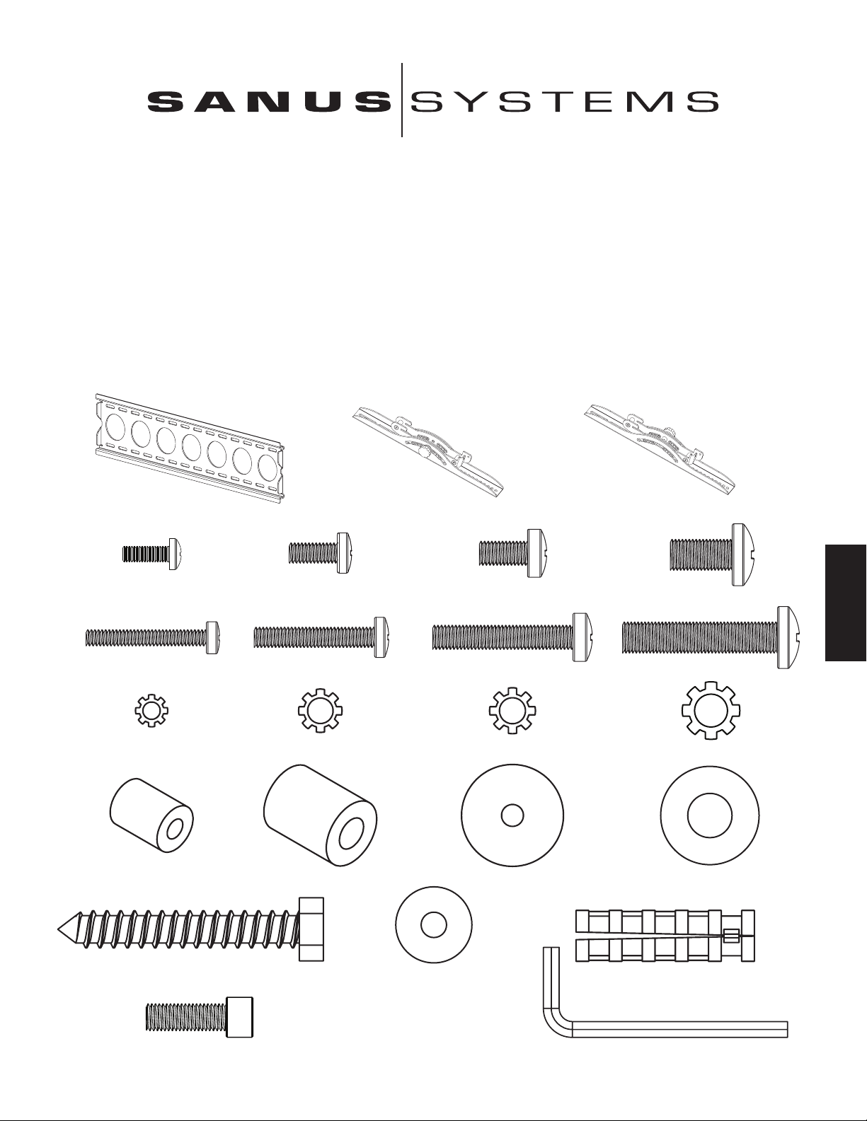
Pièces fournies : *Non illustré en grandeur réelle.
(1) Plaque murale - a* (1) Support gauche du moniteur - b* (1) Support droit du moniteur - c*
FRANÇAIS
(4) Boulon M4 x 12 - d (4) Boulon M5 x 12 - e (4) Boulon M6 x 12 - f (4) Boulon M8 x 16 - g
Boulon M4 x 30 - h (4) Boulon M5 x 30 - i (4) Boulon M6 x 35 - j (4) Boulon M8 x 40 - k
(4) Rondelle-frein M4 - l (4) Rondelle-frein M5 - m (4) Rondelle-frein M6 - n (4) Rondelle-frein M8 - o
(4) Entretoise M4/M5 - p (4) Entretoise M6/M8 - q (8) Rondelle M4/M5 - r (4) Rondelle M6/M8 - s
(6) Tire-fond - t (6) Boulon d’ancrage pour béton - v
(6) Rondelle pour tire-fond - u
(2) Boulon de sécurité - w (1) Clé Allen - x*
Page 16
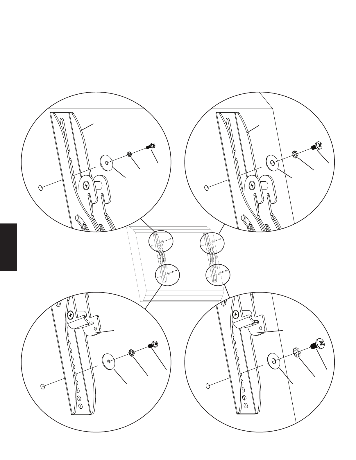
Etape 1 : Montage des supports du moniteur sur un téléviseur à panneau arrière plat
Déterminez d’abord le diamètre du boulon (d, e, f, g) que votre téléviseur nécessite en les vissant à la main dans l’insert leté du panneau arrière
du téléviseur. Si vous ressentez une résistance quelconque, arrêtez immédiatement ! Une fois le bon diamètre déterminé, reportez-vous au schéma
approprié ci-dessous. Vous devez faire passer le boulon dans la bonne rondelle-frein (l, m, n, o), puis dans la rondelle correspondante (r, s) et dans le
support du moniteur (b, c), et faire nalement passer le tout dans le téléviseur. Assurez-vous que les supports du moniteur sont centrés verticalement et
qu’ils sont au même niveau. Reportez-vous au schéma approprié ci-dessous.
Remarque : Pour les téléviseurs à panneau arrière courbé ou ceux dont l’insert leté est difcilement accessible, reportez-vous
à l’étape 2.
Boulon de diamètre M4 Boulon de diamètre M6
b c
d f
l n
r s
FRANÇAIS
Boulon de diamètre M5 Boulon de diamètre M8
b c
e g
m o
r s
Schéma 1
Remarque : Après avoir terminé l’étape 1, allez à l’étape 3.
Page 17
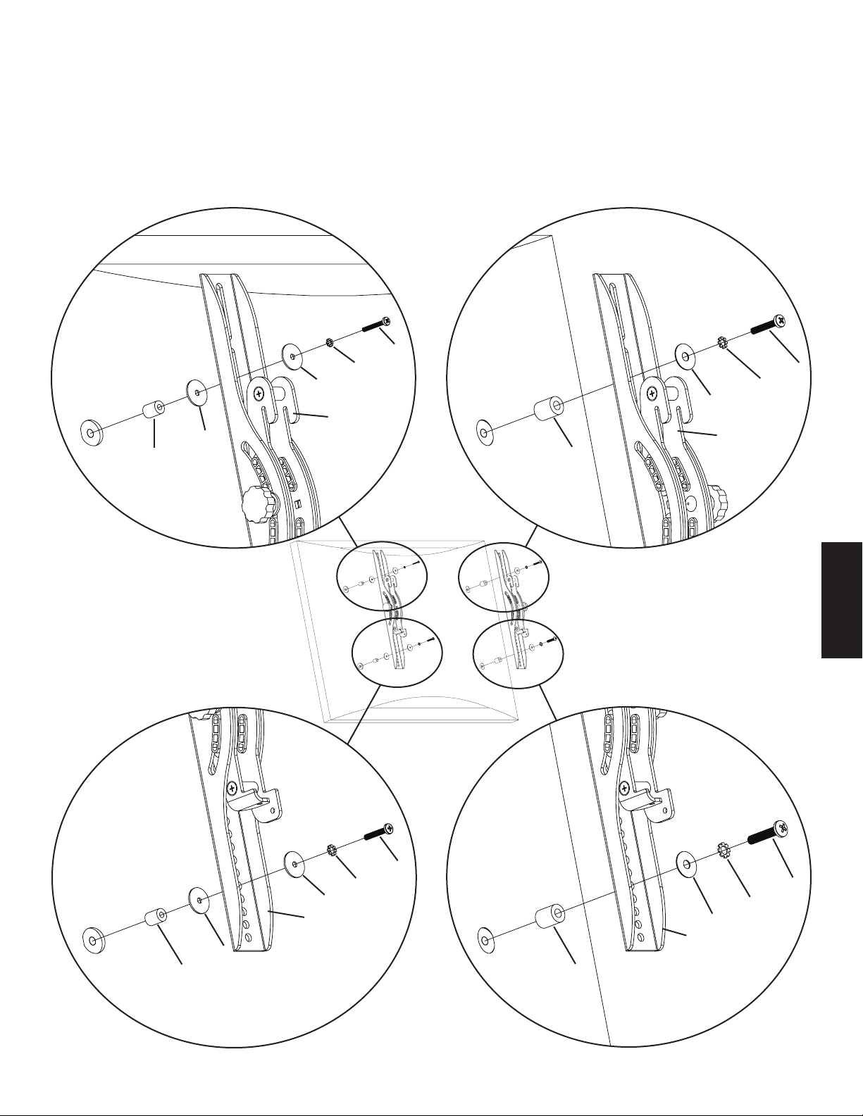
Etape 2 : Montage des supports du moniteur sur un téléviseur à panneau arrière courbé ou sur un téléviseur dont l’insert leté
est difcilement accessible
Déterminez d’abord le diamètre du boulon (h, i, j, k) que votre téléviseur nécessite en les vissant à la main dans l’insert leté du panneau arrière du
téléviseur. Si vous ressentez une résistance quelconque, arrêtez immédiatement ! Une fois le bon diamètre déterminé, reportez-vous au schéma approprié
ci-dessous. Vous devez faire passer le boulon dans la bonne rondelle-frein (l, m, n, o), puis dans la rondelle correspondante (r, s), dans le support du
moniteur (b, c), dans une entretroise (p, q), une autre rondelle (r - de diamètre M4/M5 seulement) et faire nalement passer le tout dans le téléviseur.
Assurez-vous que les supports du moniteur sont centrés verticalement et qu’ils sont au même niveau. Reportez-vous au schéma approprié ci-dessous.
Boulon de diamètre M4 Boulon de diamètre M6
h
l j
r n
s
b
r c
p q
FRANÇAIS
Schéma 2
Boulon de diamètre M5 Boulon de diamètre M8
i
m k
r o
b s
c
r
p q
Page 18
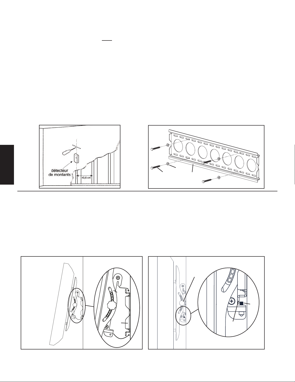
Etape 3 : Montage de la plaque murale – Les options de montage sont les suivantes : ossature de bois, brique, béton monolithe et bloc
de béton.
Montage sur ossature de bois :
La plaque murale (a) doit être montée sur deux montants de cloison distants d’au moins 30,5 cm. Servez-vous d’un détecteur de
montants de haute qualité pour repérer deux montants adjacents. Il est préférable de vérier l’emplacement des montants à l’aide d’un poinçon ou d’un
clou mince tel qu’indiqué au schéma 3a. Percez au préalable un trou de 6,4 cm de profondeur à la hauteur souhaitée sur chaque montant à l’aide d’une
mèche de 3/16 pouce. Assurez-vous que ces trous sont bien centrés sur les montants et au même niveau l’un de l’autre. Servez-vous de la plaque murale
comme modèle pour marquer l’emplacement du second trou sur chaque montant. Percez des trous de 6,4 cm de profondeur à l’aide d’une mèche de
3/16 pouce sur la marque de l’emplacement. Fixez la plaque murale sur le mur à l’aide des quatre tire-fonds (t) et des quatre rondelles pour tire-fond
(u). Assurez-vous que la plaque murale est orientée de façon à ce que la surface plane au centre de la plaque soit contre le mur et que les tire-fonds se
trouvent de chaque côté du centre de la plaque murale, tel qu’illustré au schéma 3b.
Montage sur brique, béton monolithe et bloc de béton :
Servez-vous de la plaque murale (a) comme modèle pour marquer 6 emplacements de trous sur le mur. Placez les trous extérieurs le plus loin possible
des bords extérieurs de la plaque murale. Trois sur la rangée supérieure des fentes et les trois autres sur la rangée inférieure. Assurez-vous que ces trous
sont au même niveau et que la distance entre chaque trou est d’au moins 15,2 cm. Pré-percez ces trous à l’aide d’une mèche de maçonnerie de 1/2 pouce
à une profondeur minimale de 6,4 cm. Insérez un boulon d’ancrage pour béton (v) dans chacun de ces trous. Assurez-vous que la cheville est enfoncée
et afeure complètement la surface du béton même si elle recouverte d’une couche de cloison sèche ou de tout autre matériau. Fixez la plaque murale
sur le mur à l’aide des six tire-fonds (t) et des six rondelles pour tire-fond (u).
Schéma 3a Schéma 3b
u
t a
FRANÇAIS
Etape 4 : Fixation du moniteur sur une plaque murale et installation de boulons de sécurité
Avertissement : Dans certains cas, l’intervention de 2 personnes est nécessaire pour soulever le téléviseur ! Sanus n’assume
aucune responsabilité quant aux blessures corporelles ou aux dommages du produit.
Suspension du téléviseur sur la plaque murale : Accrochez d’abord les supports du moniteur (b, c) au-dessus de la plaque murale (a), puis laissez le
bas des supports du moniteur pivoter sous le bas de la plaque murale tel qu’indiqué sur le schéma 4a. Insérez les boulons de sécurité (w) dans les
trous taraudés au bas des supports du moniteur et serrez-les à l’aide d’une clé Allen (x) pour qu’ils s’appuient sur l’arrière de la patte inférieure, sur la
plaque murale tel qu’indiqué sur le schéma 4b. Finalement, ajustez la tension des boutons des supports du moniteur ; vous pouvez à présent régler votre
nouveau téléviseur à écran plat.
Schéma 4a Schéma 4b
bouton
b, c
w
a patte
inférieure
Page 19
L ' U N I O N E D I F O R M A E F U N Z I O N E
Istruzioni di montaggio per il modello: VMPL50
Grazie per aver scelto un sistema di montaggio per parete VisionMount™. Questo prodotto è progettato per montare televisiori a pannello piatto che pesano
no a 59 kg su una parete verticale. In tal modo sarà possibile inclinare senza sforzi il nuovo televisore no a 12° in senza usare strumenti.
Avvertenza sulla sicurezza: se non si comprendono queste istruzioni o si hanno dubbi sulla sicurezza dell’installazione, rivolgersi a un installatore
specializzato o contattare la Sanus al numero 800.359.5520 (numero verde USA) o, in Europa, al numero +31 (0) 20 5708938. È anche possibile visitare
il sito www.sanus.com. La nostra assistenza clienti può rispondere rapidamente alle domande relative all’installazione o alle parti mancanti o difettose.
Le parti di ricambio per i prodotti Sanus acquistati attraverso i rivenditori autorizzati verranno spedite direttamente al cliente. Controllare attentamente
che non vi siano parti mancanti o difettose. Non utilizzare parti difettose. L’installazione errata può causare danni o lesioni gravi. Non utilizzare questo
prodotto per scopi diversi da quelli specicamente indicati dalla Sanus Systems. La Sanus Systems non è responsabile di danni o lesioni causati da
montaggio o utilizzo non corretti. Nota: la minuteria metallica fornita non è adatta a travi metalliche o a vecchie pareti di blocchi di calcestruzzo. Se
non si è sicuri della natura della parete, consultare un rappresentante locale.
Strumenti necessari: punta per trapano da 3/16 pollice, punta per muratura da 1/2 pollice per mattoni in cemento o installazioni con blocchi in
cemento, chiavi o chiavi a testa esagonale da 1/2 pollice, cacciavite Phillips.
Parti fornite: *in gura non delle dimensioni reali
(1) piastra per parete - a* (1) staffa sinistra per monitor - b* (1) staffa destra per monitor - c*
ITALIANO
(4) bullone M4 x 12 - d (4) bullone M5 x 12 - e (4) bullone M6 x 12 - f (4) bullone M8 x 16 - g
(4) bullone M4 x 30 - h (4) bullone M5 x 30 - i (4) bullone M6 x 35 - j (4) bullone M8 x 40 - k
(4) controrondella M4 - l (4) controrondella M5 - m (4) controrondella M6 - n (4) controrondella M8 - o
(4) distanziale M4/M5 - p (4) distanziale M6/M8 - q (8) rondella M4/M5 - r (4) rondella M6/M8 - s
(6) tirafondo - t (6) rondella per tirafondo - u (6) ancora per cemento - v
(2) bullone di sicurezza - w (1) chiave a brugola - x*
Page 20
Fase 1: montare le staffe del monitor al televisore con retro piatto
Innanzitutto, stabilire il diametro dei bulloni (d, e, f, g) che devono essere avvitati a mano alla TV nell’inserto lettato sul retro della TV.
Se si incontrano delle resistenze, bloccarsi immediatamente! Una volta determinato il diametro corretto, vedere la Figura appropriata
che segue. Il bullone viene avvitato attraverso la controrondella appropriata (l, m, n, o) la rondella corrispondente (r, s), la staffa del
monitor (b, c) e nale nella TV. Assicurarsi che le staffe per monitor siano centrate verticalmente e a livello l’una con l’altra. Vedere la
Figura appropriata che segue.
Nota: per televisori con retro curvo o per un’ostruzione accanto all’inserto lettato, vedere la Fase 2.
Bullone di diametro M4 Bullone di diametro M6
b c
d f
l n
r s
Figura 1
ITALIANO
Bullone di diametro M5 Bullone di diametro M8
b c
e g
m o
r s
Nota: dopo aver completato la Fase 1, passare alla Fase 3.
Page 21
Fase 2: montare le staffe del monitor al televisore con retro curvo o un’ostruzione accanto all’inserto lettato
Innanzitutto, stabilire il diametro dei bulloni (h, i, j, k) che devono essere avvitati a mano alla TV nell’inserto lettato sul retro della TV.
Se si incontrano delle resistenze, bloccarsi immediatamente! Una volta determinato il diametro corretto, vedere la Figura appropriata che
segue. Il bullone viene avvitato attraverso la controrondella appropriata (l, m, n, o) la rondella corrispondente (r, s), la staffa del monitor
(b, c) un distanziale (p, q), una seconda rondella (r - solo M4/M5) e inne nella TV. Assicurarsi che le staffe per monitor siano centrate
verticalmente e a livello l’una con l’altra. Vedere la Figura appropriata che segue.
Bullone di diametro M4 Bullone di diametro M6
h
l j
r n
s
b
r c
p q
Figura 2
Bullone di diametro M5 Bullone di diametro M8
i
m k
r o
b s
c
r
p q
ITALIANO
Page 22
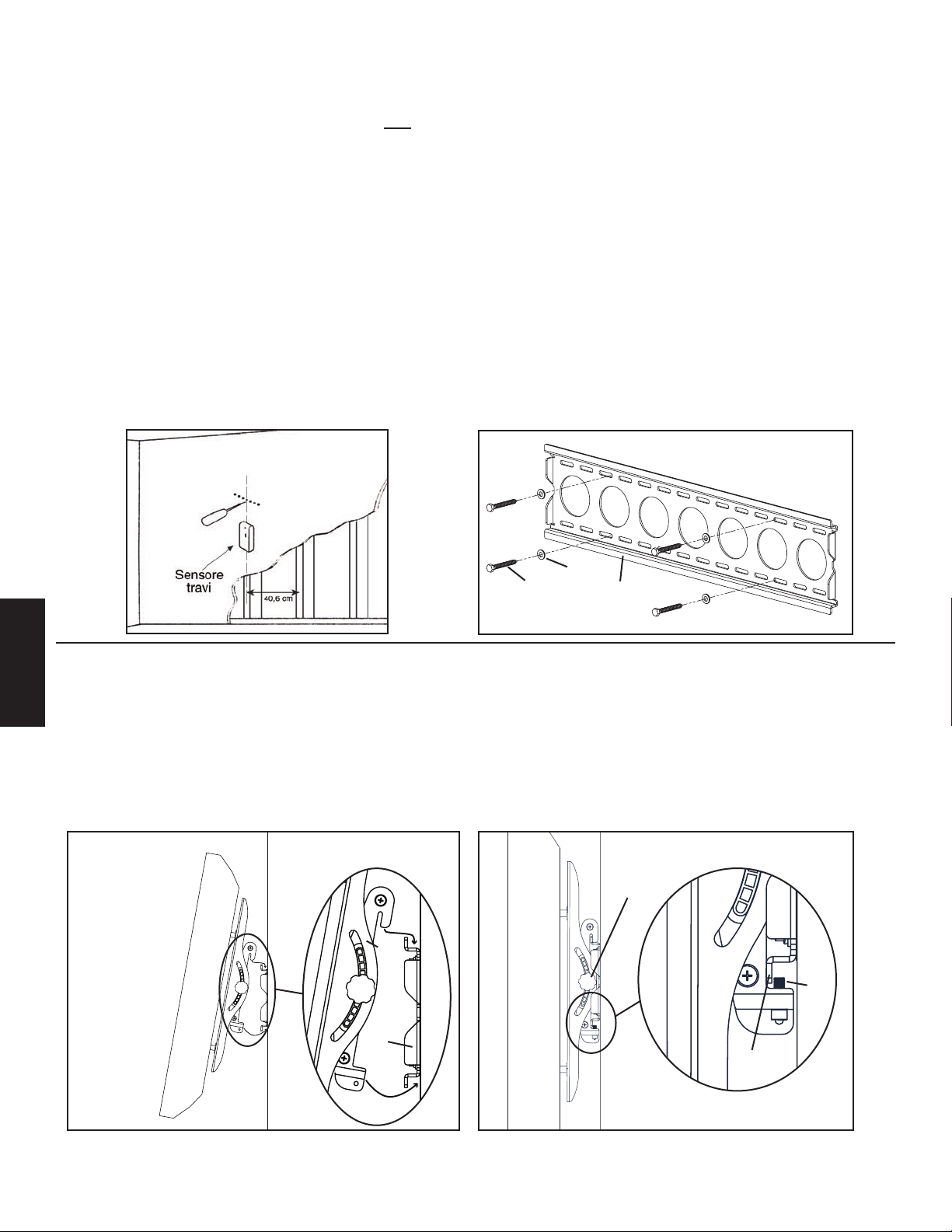
Fase 3: montare la piastra a parete: Sono disponibili le opzioni di montaggio su travi di legno, mattoni, cemento e blocchi
di cemento.
Montaggio su travi di legno:
La piastra a parete (a) deve essere montata su due travi di legno distanti almeno 30,5 cm. Usare un rilevatore di travi in
legno di alta qualità per individuare due travi in legno adiacenti. È una buona idea vericare la posizione delle travi in legno con un
punteruolo o con un chiodo sottile come nella Figura 3a. Forare in precedenza un foro ad una profondità di 6,4 cm alla quota desiderata
di ogni trave di legno usando una punta per trapano da 3/16 pollice. Assicurarsi che questi fori vengano praticati nell’area centrale delle
travi e allo stesso livello fra loro. Utilizzare la piastra a parete come maschera per contrassegnare la posizione in ogni trave. Forare fori
a una profondità di 6,4 cm usando una punta per trapano da 3/16 pollice nella posizione contrassegnata. Collegare la piastra per parete
alla parete usando i quattro tirafondi (t) e le due rondelle per tirafondo (u). Assicurarsi che la piastra per parete sia orientata in modo che
la supercie piatta al centro della piastra sia contro la parete e che una serie di tirafondi si trovi su ogni lato del centro della piastra per
parete come mostrato nella Figura 3b.
Montaggio per mattone, cemento solido e blocco di cemento:
Utilizzare la piastra a parete (a) come maschera per contrassegnare 6 posizioni per fori sulla parete. Individuare i fori esterni il più
lontano possibile dai bordi delle piastra per parete. Tre nella la superiore degli alloggiamenti e altri tre nella la inferiore. Assicurarsi
che questi fori siano a livello e vi siano almeno 15,2 cm tra ogni due fori. Effettuare con cura un foro preliminare ad una profondità di
almeno 6,4 cm usando una punta per muratura da 1/2 pollice. Inserire un’ancora per cemento (v) in ognuno di questi fori. Assicurarsi che
l’ancora sia sistemata completamente a livello con la supercie di cemento anche se vi è uno strato di stucco o altro materiale davanti.
Collegare la piastra per parete alla parete usando i sei tirafondi (t) e le sei rondelle per tirafondi (u).
Figura 3a Figura 3b
u
t a
Fase 4: Collegamento del monitor alla piastra per parete e aggiunta dei bulloni di sicurezza
Avvertenza: per sollevare alcuni televisori possono essere necessarie 2 persone. La Sanus non è responsabile di
eventuali lesioni personali o dani al prodotto.
ITALIANO
Appendere la TV sulla piastra per parete: Innanzitutto agganciare le staffe per monitor (b, c) sulla parte superiore della piastra per parete
(a), quindi consentire alla parte inferiore delle staffe per monitor di ruotare verso l’interno sotto la parte inferiore della staffa per parete
come mostrato nella Figura 4a. inserire i bulloni di sicurezza (w) nei fori lettati nella parte inferiore delle staffe per monitor e serrarli con
la chiave a brugola (x) in modo che siano inseriti dietro la linguetta inferiore sulla piastra per parete come mostrato nella Figura 4b. Inne
apporre tensione sulle manopole sulle staffe per monitor: a questo punto si è liberi di regolare il nuovo televisore a pannello piatto.
Figura 4a Figura 4b
manopola
b,c
w
a
parte inferiore
linguetta
Page 23
Инструкция по сборке крепления модели VMPL50
Благодарим Вас за приобретение настенного крепления Sanus Systems VisionMount™. Крепление VMPL50 предназначено для
установки плоскопанельных телевизоров весом до 59 кг на вертикальные стены. Устройство позволяет легко регулировать
ориентацию телеэкрана в пределах 12° вверх и вниз без использования инструментов.
Внимание! Если Вам непонятны приведенные ниже инструкции, или если возникают любые сомнения по поводу безопасности
использования установленного устройства, обратитесь к квалифицированному специалисту или в компанию Sanus по телефону
800-359-5520 (США) или 31 (0) 20 5708938 (Европа). Вы также можете посетить наш веб-сайт www.sanus.com. Мы незамедлительно
поможем Вам разрешить вопросы по поводу установки устройства и недостающих либо поврежденных его частей. Запасные части
к изделиям компании Sanus, приобретенным через уполномоченных агентов по продаже, будут доставлены непосредственно по
указанному Вами адресу. Тщательно проверьте наличие всех деталей и отсутствие заводского брака. Не используйте бракованные
детали. Неправильная установка устройства может привести к травмированию людей и порче имущества. Это изделие может
применяться исключительно в целях, прямо указанных производителем. Компания Sanus Systems не несет ответственности за
вред здоровью или материальный ущерб, причиненный вследствие неправильной сборки, монтажа и эксплуатации устройства.
Примечание: Настоящее крепежное оборудование не предназначено для монтажа на стенах со стальным каркасом или старых
шлакобетонных стенах. Если Вы не можете с уверенностью судить о конструкции стены, обратитесь в строительную организацию.
Необходимые инструменты: сверло на 3/16 дюйма, тонкостенная алмазная коронка на 1/2 дюйма для установки на кирпичной
стене, монолитной бетонной или панельной бетонной стене, ключ или торцовая насадка 1/2 дюйма, крестообразная отвертка.
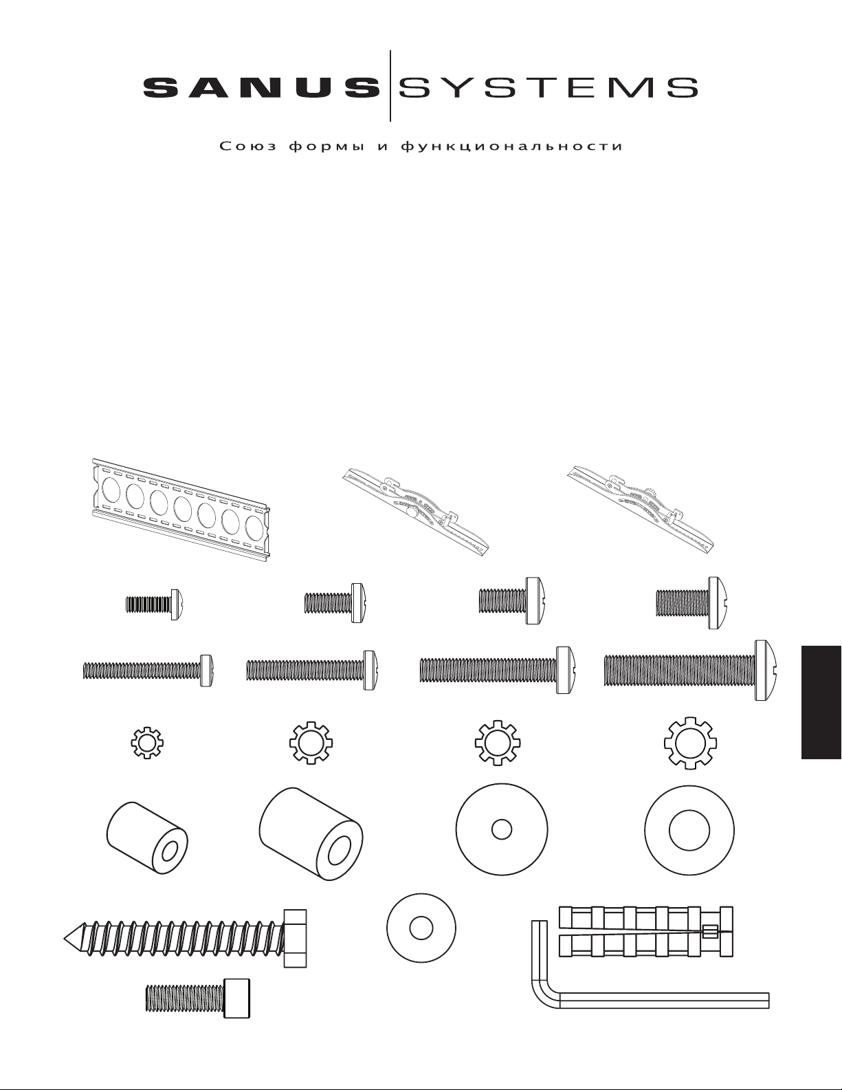
Комплект поставки: *Изображены в масштабе.
Настенная крепежная пластина (a*) – 1 шт. Левая крепежная скоба для монитора (b*) – 1 шт. Правая крепежная скоба для монитора (c*) – 1 шт.
Винт M4 x 12 (d) – 4 шт. Винт M5 x 12 (e) – 4 шт. Винт M6 x 12 (f) – 4 шт. Винт M8 x 16 (g) – 4 шт.
Винт M4 x 30 (h) – 4 шт. Винт M5 x 30 (i) – 4 шт. Винт M6 x 35 (j) – 4 шт. Винт M8 x 40 (k) – 4 шт.
Шайба стонорная M4 (l) – 4 шт. Шайба стонорная M5 (m) – 4 шт. Шайба стонорная M6 (n) – 4 шт. Шайба стонорная M8 (o) – 4 шт.
Шайба установочная M4/М5 (p) – 4 шт. Шайба установочная M6/М8 (q) – 4 шт. Шайба M4/М5 (r) – 8 шт. Шайба M6/М8 (s) – 4 шт.
Шуруп под ключ (t) – 6 шт. Шайба под шуруп под ключ (u) – 6 шт. Дюбель для бетона (v) – 6 шт.
PYCCKO
Предохранительный болт (w) – 2 шт. Ключ шестигранный (x*) – 1 шт.
Page 24
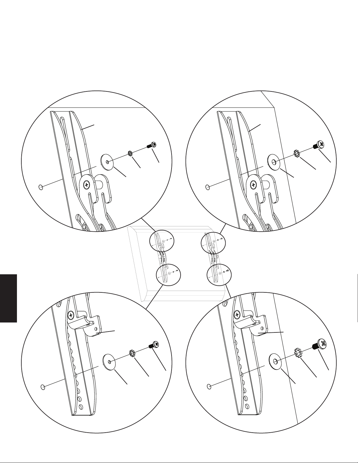
Шаг 1. Прикрепление крепежных скоб к телевизору с плоской задней панелью.
Сначала нужно определить диаметр винта (d, e, f, g) , который подходит для Вашего телевизора. Для этого попробуйте вручную
ввинтить каждый винт в заднюю панель телевизора. Почувствовав сопротивление, немедленно прекратите ввинчивать винт!
Определив нужный диаметр, рассмотрите соответствующий рисунок ниже. Винт следует завинтить через соответствующую
стонорную шайбу (l, m, n, o), шайбу (r, s) и крепежную скобу для монитора (b, c) в заднюю панель телевизора. Крепежные скобы
должны быть прикреплены на одном уровне и центрированы по вертикали. См. соответствующий рисунок ниже.
Примечание: если задняя панель телевизора искривлена, или возле вставки с резьбой имеется мешающий выступ, см. шаг 2.
Винт диаметра M4 Винт диаметра M6
b c
d f
l n
r s
Рисунок 1
Винт диаметра M5 Винт диаметра M8
PYCCKO
b c
e g
m o
r s
Примечание: Выполнив шаг 1, переходите к шагу 3.
Page 25
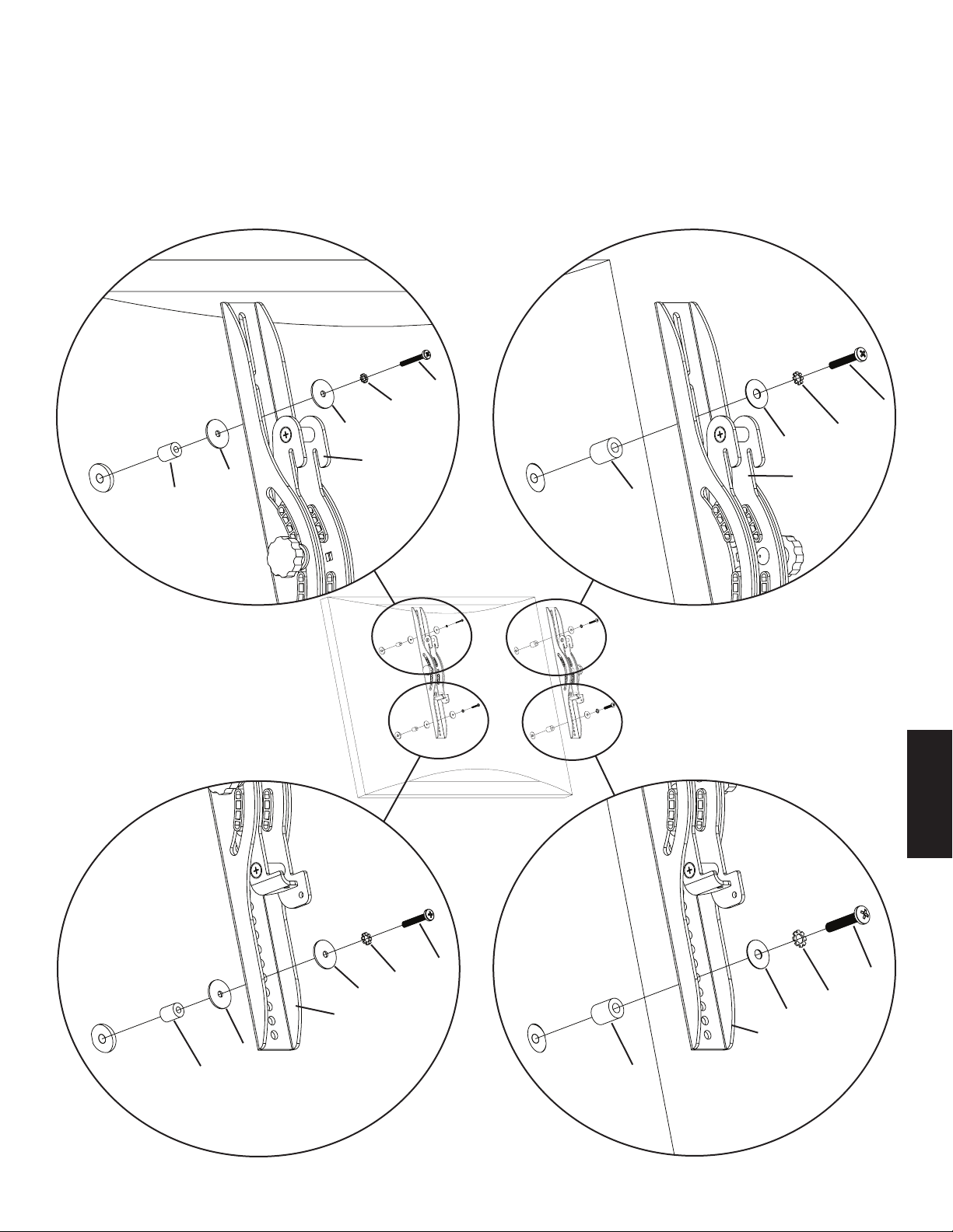
Шаг 2. Прикрепление крепежных скоб к телевизору с искривленной задней панелью или с выступом возле резьбовой вставки.
Сначала нужно определить диаметр винта (h, i, j, k), который подходит для Вашего телевизора. Для этого попробуйте вручную
ввинтить каждый винт в заднюю панель телевизора. Почувствовав сопротивление, немедленно прекратите ввинчивать винт!
Определив нужный диаметр, рассмотрите соответствующий рисунок ниже. Винт следует завинтить через соответствующую
стонорную шайбу (l, m, n, o), соответствующую шайбу (r, s), крепежную скобу для монитора (b, c), установочную шайбу (p, q), еще
одну шайбу (r - только диаметра M4/M5) в заднюю панель телевизора. Крепежные скобы должны быть прикреплены на одном
уровне и центрированы по вертикали. См. соответствующий рисунок ниже.
Винт диаметра M4 Винт диаметра M6
h
l j
r n
s
b
r c
p q
Рисунок 2
Винт диаметра M5 Винт диаметра M8
i
m k
r o
b s
c
r
p q
PYCCKO
Page 26
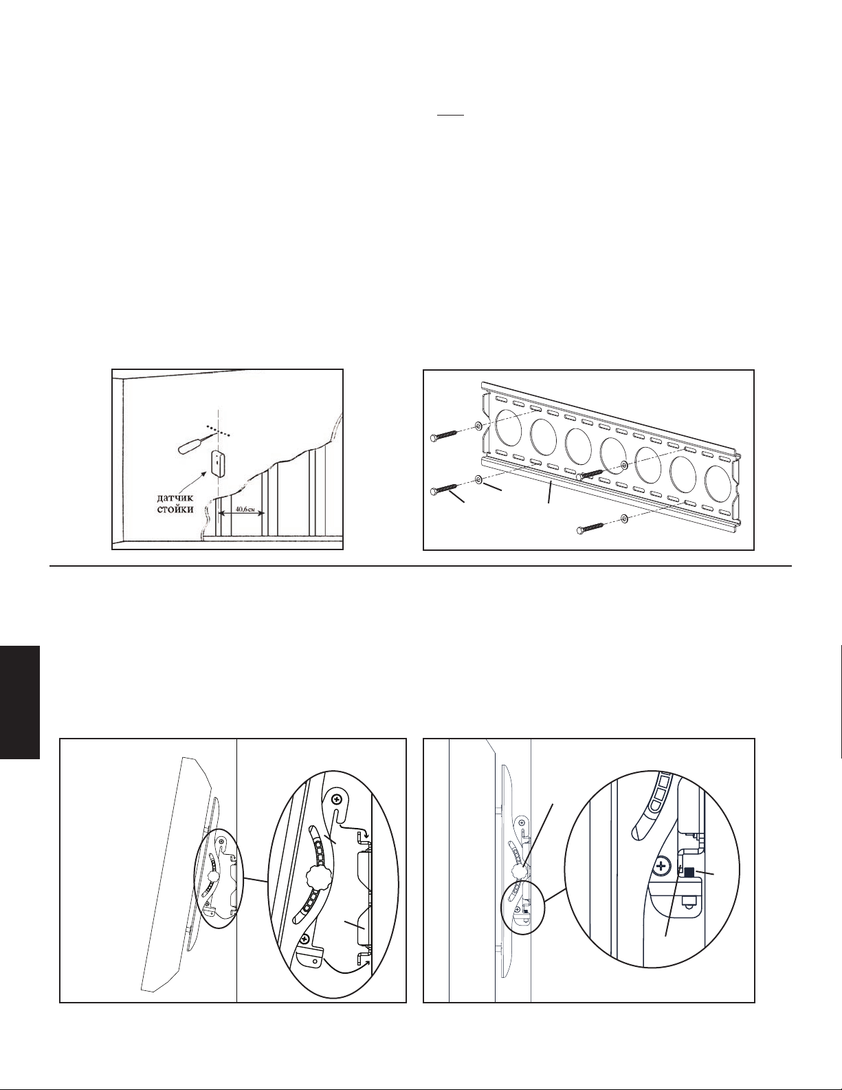
Шаг 3. Установка пластины. крепежной пластины. Крепление может фиксироваться к деревянной стойке, кирпичной, бетонной
монолитной или бетонной панельной стене.
Монтаж на деревянной стойке каркасной стены
Настенная крепежная пластина (a) должна быть прикреплена к двум деревянным стойкам на расстоянии не менее 30,5 см.
Для определения местонахождения двух соседних деревянных стоек следует использовать высокочувствительный датчик.
Целесообразно проверить, правильно ли определено местонахождение стоек, с помощью шила или тонкого гвоздя, как показано
на рисунке 3а. С помощью сверла 3/16 дюйма просверлите в каждой стойке черновое отверстие глубиной 6,4 см на необходимой
высоте. Убедитесь, что отверстия сделаны по центру стоек и на одной высоте. Используйте настенную крепежную пластину в
качестве шаблона для определения места для второго отверстия в каждой стойке. Просверлите с помощью сверла 3/16 дюйма в
отмеченных точках отверстия глубиной 6,4 см. Прикрепите настенную крепежную пластину к стене, используя два шурупа под
ключ (t) и две шайбы для шурупов под ключ (u). Настенная крепежная пластина должна прилегать плоским участком в центре к
стене. С каждой стороны в пластину должны быть ввинчены шурупы под ключ, как показано на рисунке 3b.
Монтаж на кирпичной, монолитной или панельной бетонной стене
Используйте настенную крепежную пластину (a) в качестве шаблона, чтобы определить место для 6 отверстий на стене. Наружные
отверстия следует наметить как можно дальше от середины настенной крепежной пластины. Следует просверлить по три отверстия
напротив нижнего и верхнего рядов прорезей в пластине. Отверстия должны находиться на одном уровне и на расстоянии не менее
15,2 см друг от друга. Просверлите черновые отверстия глубиной не менее 6,4 см, используя тонкостенную алмазную коронку на
1/2 дюйма. Вставьте дюбель для бетона (v) в каждое из отверстий. Убедитесь, что дюбель надежно закреплен, даже если сверху
бетон покрыт слоем сухой штукатурки или других материалов. Прикрепите настенную крепежную пластину к стене, используя
шесть шурупов под ключ (t) и шесть шайб для шурупов под ключ (d).
Рисунок 3а Рисунок 3b
u
t a
Шаг 4. Установка монитора на настенную крепежную пластину. Установка предохранительных болтов
Внимание! Чтобы поднять телевизоры некоторых моделей, может потребоваться два человека! Компания Sanus не несет
ответственности за травмы и порчу имущества.
Прикрепление телевизора к настенной крепежной пластине Сначала установите крепежные скобы монитора (b, c) на настенную
крепежную пластину (а). Крепежные скобы повернутся и войдут нижней частью под настенную пластину, как показано на рисунке
4а. Вставьте предохранительные болты (w) в отверстия c резьбой в нижней части скоб монитора и затяните их с помощью торцового
ключа (x). Предохранительные болты должны скрыться за нижним выступом настенной крепежной пластины, как показано на
рис. 4b. Ослабьте фиксирующие ручки на скобах монитора, и Вы сможете изменить положение и ориентацию в пространстве
плоскоэкранного телевизора.
Рисунок 4а Рисунок 4b
PYCCKO
Ручка
b,c
w
a
Нижний
выступ
Page 27
VMPL50 モデルの組み立て説明書
Sanus Systems VisionMount™ 壁掛け製品をお買い上げいただきありがとうございます。本製品は、59 kg までのフラットパネルテレビを垂直
な壁面に取り付けるよう設計されています。当製品のご利用により、新型テレビを道具なしでも最大 12 度まで傾けることができます。
安全性に関する警告:ここに記載されている説明ではよくわからない場合、もしくは設置上の安全性について疑問がある場合は、有資格の契約
業者にお電話いただくか、Sanus (米国: 800-359-5520 もしくは、ヨーロッパ: 31-(0)-20-5708938) までご連絡ください。弊社ウェブサイ
ト www.sanus.com もご覧いただけます。設置に関するご質問または部品の不足や損傷について迅速に対応させていただきます。指定販売店
でお求めいただいた製品については、交換部品をお客様に直接お届けいたします。不足や破損している部品がないかよく確認してください。破損
した部品は絶対に使用しないでください。設置方法が不適切な場合、破損や深刻なケガを引き起こすおそれがあります。Sanus Systems が明
記している目的以外でこの製品を使用しないでください。Sanus Systems は、取り付け、組立、使用が正しく行われていないことに起因する破
損、ケガについては責任を負いかねます。注意:同梱の金具は、スチール製の間柱や旧式の軽量コンクリートブロックの壁には使用できません。壁
の材質がわからない場合は、お近くの設置業者にお問い合わせください。
必要な工具:3/16 インチのドリルビット、レンガ、コンクリート、コンクリートブロックに設置する場合は 1/2 インチのコンクリート用ビット、
1/2 インチのレンチまたはソケット、プラスドライバー
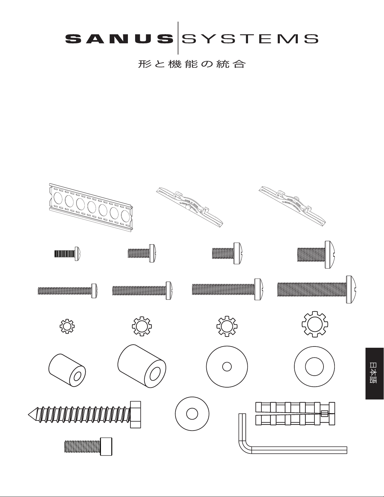
梱包部品:*表示は実サイズではありません。
(1) 壁面プレート - a* (1) モニター取り付け金具(左) - b* (1) モニター取り付け金具(右)- c*
(4) M4 x 12 ボルト - d (4) M5 x 12 ボルト - e (4) M6 x 12 ボルト - f (4) M8 x 16 ボルト - g
(4) M4 x 30 ボルト - h (4) M5 x 30 ボルト - i (4) M6 x 35 ボルト - j (4) M8 x 40 ボルト - k
(4) M4 ロックワッシャー - l (4) M5 ロックワッシャー - m (4) M6 ロックワッシャー - n (4) M8 ロックワッシャー - o
(4) M4/M5 スぺーサー - p (4) M6/M8 スぺーサー - q (8) M4/M5 ワッシャー - r (4) M6/M8 スぺーサー - s
(6) ラグボルト - t (6) コンクリートアンカー - v
(6) ラグボルトワッシャー - u
(2) 安全ボルト - w (1) アレンキー - x*
Page 28
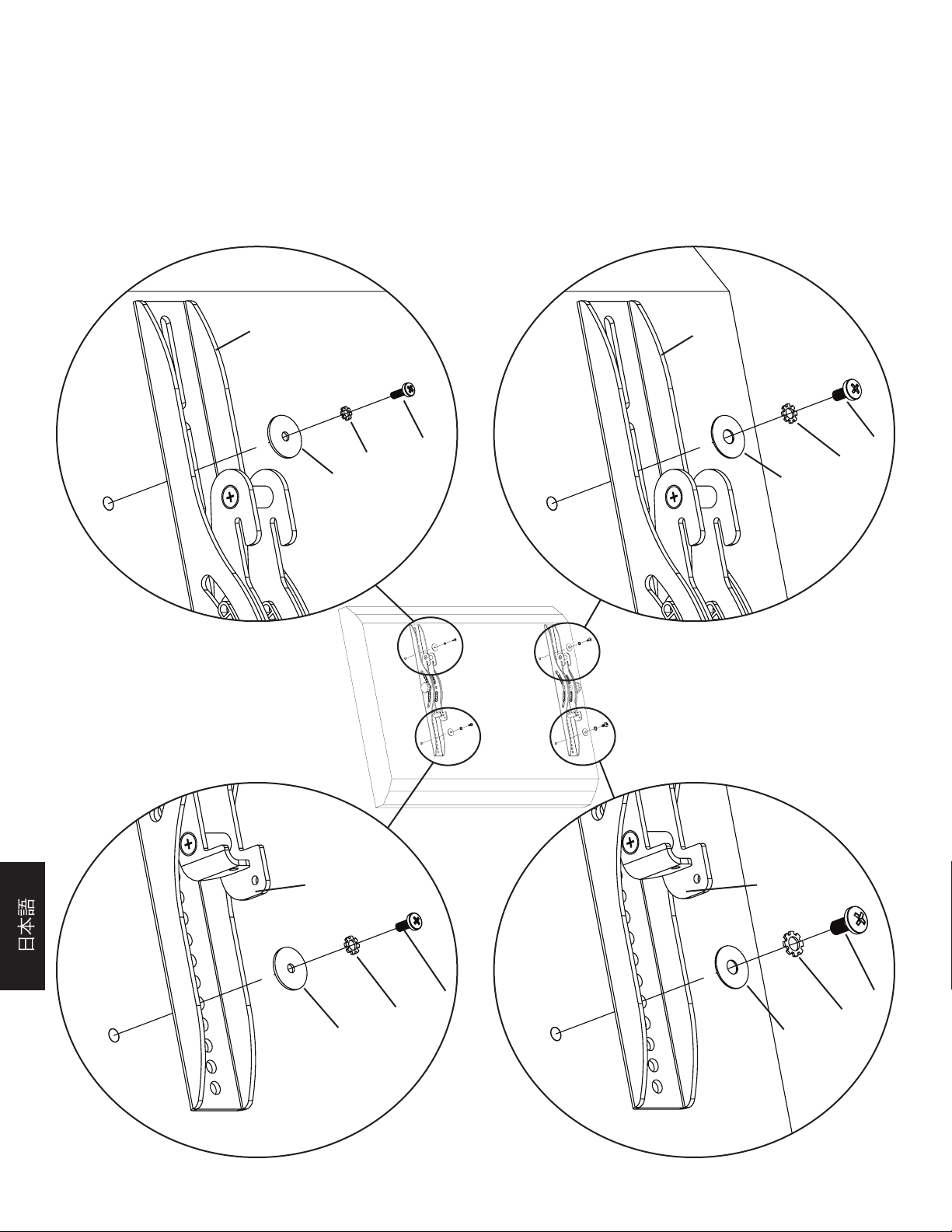
手順 1:背面が平らなテレビにモニター取り付け金具を取り付ける
まず、テレビの背面にあるねじ込みインサートに各種ボルト (d、e、f、g) を手で差し込んでみて、ご使用のテレビに適したボルトの直径を選定しま
す。電気抵抗を感じたら、すぐに中断してください!適切な直径が決まったら、以下の該当する図説をご覧ください。ボルトを適切なロックワッシャ
ー (l、m、n、o)、対応するワッシャー (r、s)、モニター取り付け金具 (b、c) に通した後、テレビに差し込みます。モニター取り付け金具が中央の高
さに位置し、金具同士が平行になっていることを確認します。以下の該当する図説をご覧ください。
注意:背面が丸くなっていたり、ネジ込みインサートの近くに凹凸のあるテレビについては、手順 2 をご覧ください。
M4 径ボルト M6 径ボルト
b c
d f
l n
r s
図 1
M5 径ボルト M8 径ボルト
b c
e g
m o
r s
注意:手順 1が終了したら、手順 3 に進みます。
Page 29
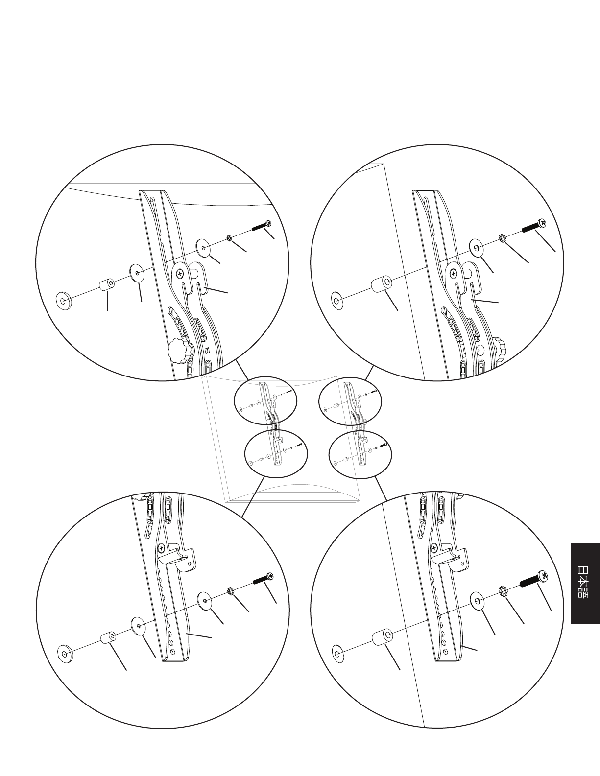
手順 2:背面が丸くなっていたり、ネジ込みインサートの近くに凹凸のあるテレビにモニター取り付け金具を取り付ける
まず、テレビの背面にあるねじ込みインサートに各種ボルト (h、i、j、k) を手で差し込んでみて、ご使用のテレビに適したボルトの直径を選定しま
す。電気抵抗を感じたら、すぐに中断してください!適切な直径が決まったら、以下の該当する図説をご覧ください。ボルトを適切なロックワッシ
ャー (l、m、n、o)、対応するワッシャー (r、s)、モニター取り付け金具(b、c)、スペーサー (p、q) 、2 つめのワッシャー (r - M4/M5 径の場合の
み) に通した後、テレビに差し込みます。モニター取り付け金具が中央の高さに位置し、金具同士が平行になっていることを確認します。以下の該
当する図説をご覧ください。
M4 径ボルト M6 径ボルト
h
l j
r n
s
b
r c
p q
図 2
M5 径ボルト M8 径ボルト
i
m k
r o
b s
c
r
p q
Page 30
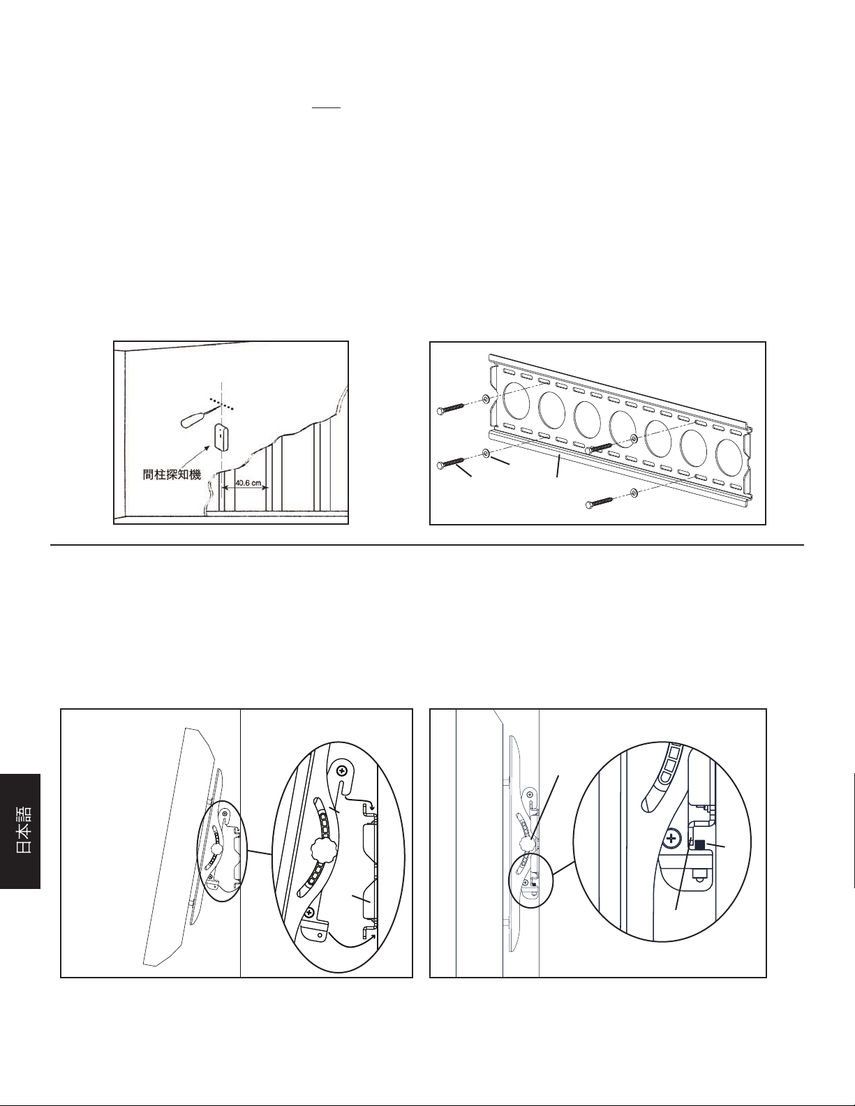
手順 3:壁面プレートを取り付ける:木製の間柱、レンガ、コンクリート、コンクリートブロックに取り付けるオプションがあります。
木製の間柱に取り付ける:
壁面プレート (a) は、必ず 30.5 cm 以上離れた 2 本 の木製の間柱に取り付けるようにしてください。高性能の間柱探知機を使って、間柱の位
置を調べます。図 3a のように、千枚通しか細い釘で間柱の位置を再確認しておくとよいでしょう。3/16 インチのドリルビットを使って、それぞれ
の間柱の適当な高さに、予め奥行き 6.4 cm の穴を開けておきます。これらの穴が間柱の中心にあり、穴同士が水平であることを確認します。壁
面プレートをテンプレートにして、各間柱に開ける 2 つめの穴の位置に印を付けます。3/16 インチのドリルビットを使って、印をした位置に奥行
き 6.4 cm の穴を開けます。4 本のラグボルト (t) と 4 個のラグボルトワッシャー (u) を使って、壁面プレートを壁に取り付けます。図 3b のよ
うに、プレート中央の平らな面が壁に接し、ラグボルトのセットが壁面プレート中央の四方に配置されるように壁面プレートの向きを確認します。
レンガ、コンクリート、コンクリートブロックに取り付ける:
壁面プレート (a) をテンプレートにして、壁に開ける 6 つの穴の位置に印を付けます。外側の穴はできるだけ壁面プレートの外側になるようにし
ます。スロットの上列に 3 つ、下列に 3 つの穴を開けます。これらの穴が水平で、2 つの穴の間隔がどこも15.2 cm 以上であることを確認しま
す。1/2 インチのコンクリート用ビットを使って、奥行き 6.4 cm の穴を予め開けておきます。各穴にコンクリートアンカー (v) を挿入します。コン
クリートの上にドライウォールやその他の材質の層がある場合でも、アンカーがコンクリート面に完全に設置されていることを確認します。6 本
のラグボルト (t) と 6 個のラグボルトワッシャー (u) を使って、壁面プレートを壁に取り付けます。
図 3a 図 3b
u
t a
手順 4:モニターを壁面プレートに取り付け、安全ボルトを設置する
警告:テレビによっては 2 人で持ち上げる必要があります!Sanus では、ケガや製品の破損についての責任は負いかねます。
テレビを壁面プレートに掛ける:図 4a のように、まずモニター取り付け金具 (b、c) を壁面プレート (a) の上端に引っ掛け、 モニター取り付け金
具の下部を回転させて壁面プレートの下側にはめ込みます。安全ボルト (w) をモニター取り付け金具の底部にあるネジ穴に差し込んでアレンキ
ー (x) で固定します。これで、図 4b のように、安全ボルトが壁面プレートの下部にあるタブの後ろに設置されます。最後にモニター取り付け金具
のノブの締め具合を操作して、新型フラットパネルテレビを自在に調整します。
図 4a 図 4b
ノブ
b、c
w
a
下部にある
タブ
Page 31
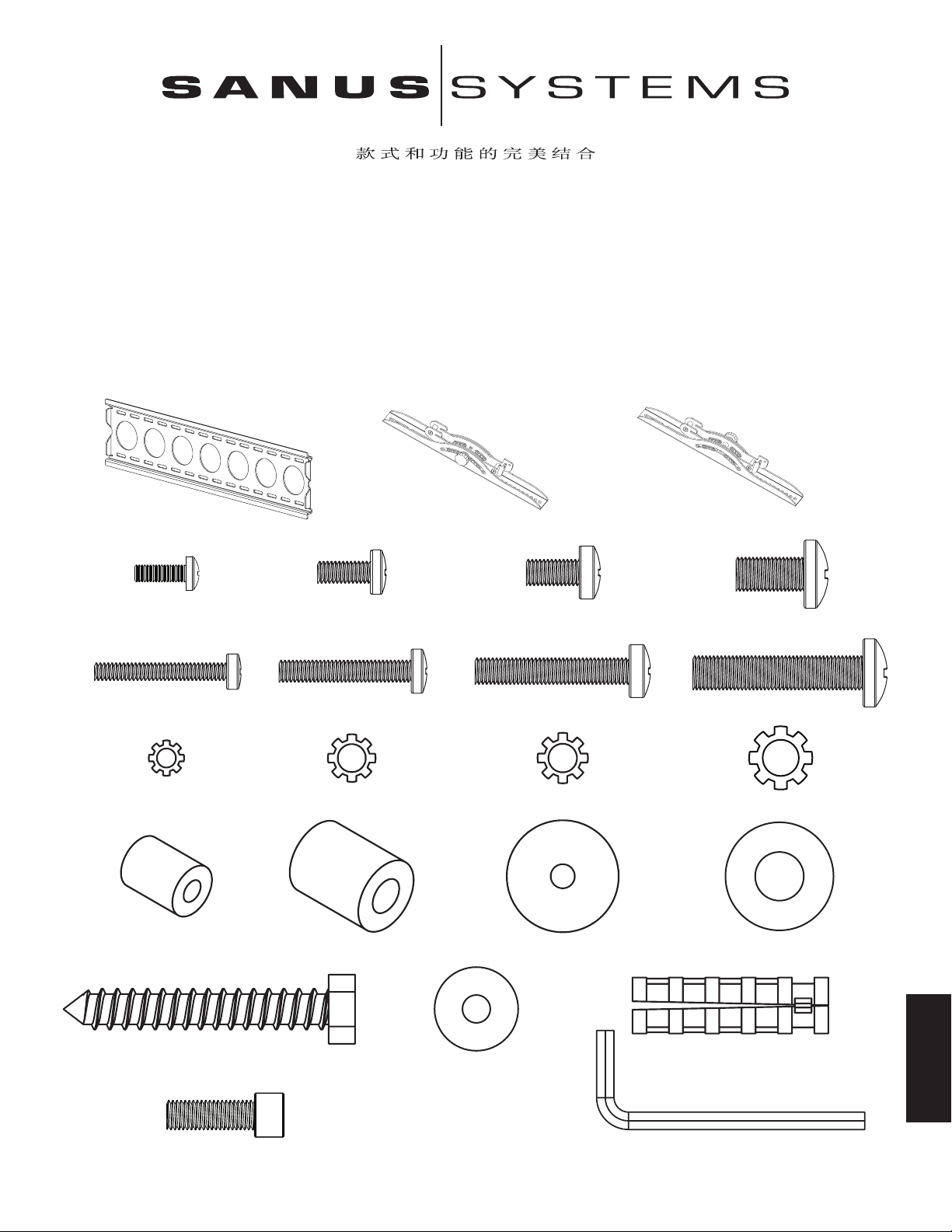
VMPL50 型号装配说明
感谢您选用 VisionMount™ 墙架。此款产品设计用于将平板电视机安装至垂直的墙面上,承重可达 59 公斤。使用此产品后,您不必使用
任何工具就可毫不费力地将新电视机倾斜达 12°角。
安全警告:如果您不理解这些说明或对安装的安全性有任何疑问,请致电有资格的承包商或与 Sanus 联系,联系电话:800.359.5520(美国)或
31 (0) 20 5708938(欧洲)。您也可以访问我们的网站 www.sanus.com。我们将迅速协助您解决安装问题及零件缺少或损坏的问题。对通过
授权经销商所购 Sanus 产品的替换零件将直接送货上门。请仔细检查以确保零件无缺少或缺陷。切勿使用有缺陷的零件。安装不正确可
能会导致损坏或严重受伤。切勿将本品用于 Sanus Systems 未明示的任何其它目的。Sanus Systems 对由于安装不正确、装配不正确或使
用不当引起的损坏或受伤不承担任何责任。注意:所提供的五金件不能用于钢制墙筋墙或旧煤渣砖墙。如果您不确定墙的种类,请咨询装
置承办商。
必需的工具: 3/16 英寸钻头、用于砖混凝土或混凝土砌块建筑的 1/2 英寸 圬工钻头、1/2 英寸 扳手或套筒、飞利浦 螺丝刀。
提供的零件:*未按实际尺寸显示。
(1) 墙板 - a* (1) 左侧显示器架 - b* (1) 右侧显示器架 - c*
(4) M4 x 12 螺钉 - d (4) M5 x 12 螺钉 - e (4) M6 x 12 螺钉 - f (4) M8 x 16 螺钉 - g
(4) M4 x 30 螺钉 - h (4) M5 x 30 螺钉 - i (4) M6 x 35 螺钉 - j (4) M8 x 40 螺钉 - k
(4) M4 锁紧垫圈 - l (4) M5 锁紧垫圈 - m (4) M6 锁紧垫圈 - n (4) M8 锁紧垫圈 - o
(4) M4/M5 间隔块 - p (4) M6/M8 间隔块 - q (8) M4/M5 垫圈 - r (4) M6/M8 垫圈 - s
(6) 方头螺栓 - t (6) 膨胀螺丝 - v
(6) 方头螺栓垫圈 - u
中文
(2) 安全螺钉 - w (1) 内六角扳手 - x*
Page 32
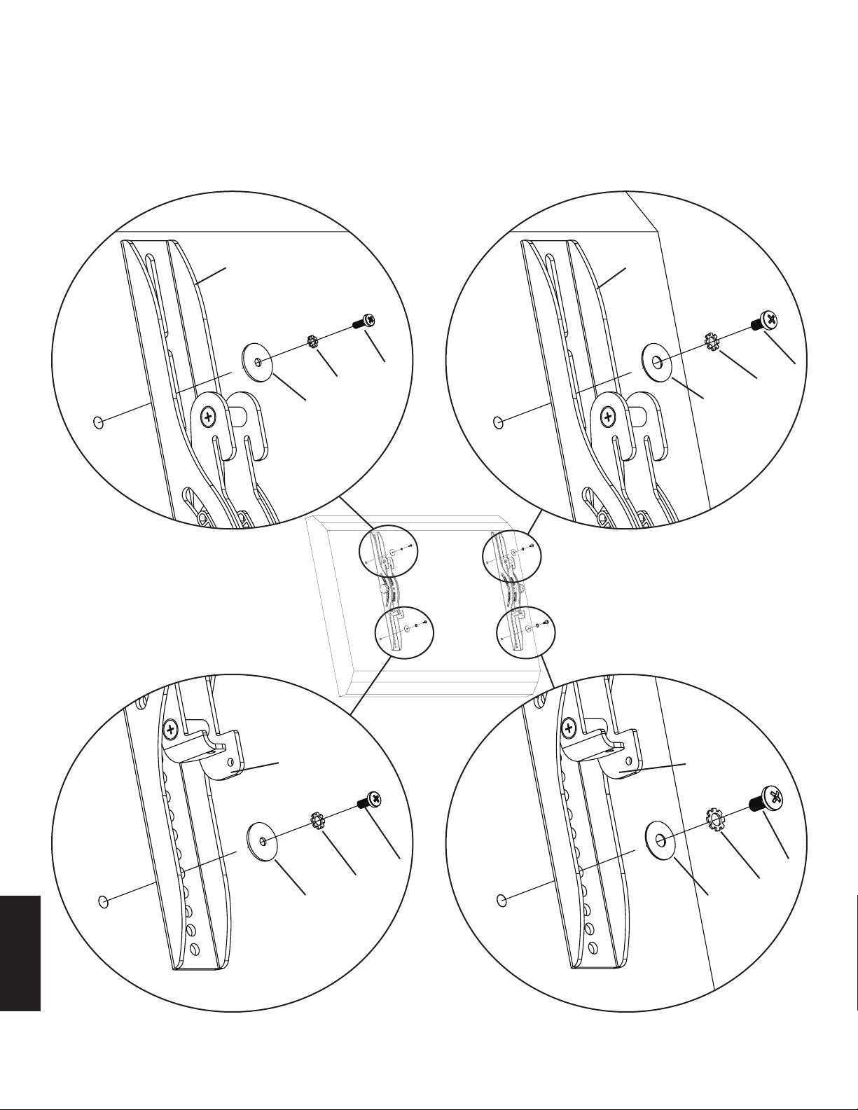
步骤 1:将显示器架安装到平背面电视机上
首先,用手将螺钉 (d, e, f, g) 旋入电视机背面的螺孔以确定电视机所需螺钉的直径。如果遇到任何阻力,请立即停止!确定
正确的直径后,请查看如下相应图示。螺钉将依次插入锁紧垫圈 (l, m, n, o)、对应垫圈 (r, s) 和显示器架 (b, c),并最终插入
电视机中。请确保两个显示器架垂直居中且相互齐平。请参阅如下相应图示。
注意:如果电视机背面为曲面或在螺孔旁存在障碍物,请参见步骤 2。
M4 直径螺钉 M6 直径螺钉
b c
d f
l n
r s
图 1
M5 直径螺钉 M8 直径螺钉
b c
e g
m o
r s
中文
注意:步骤 1 完成后,请执行步骤 3。
Page 33
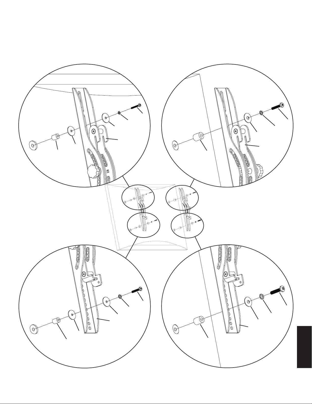
步骤 2:为曲背面或螺孔旁有障碍物的电视机安装显示器架
首先,用手将螺钉 (h, i, j, k) 旋入电视机背面的螺孔以确定电视机所需螺钉的直径.如果遇到任何阻力,请立即停止!确定正
确的直径后,请查看如下相应图示。螺钉将分别插入锁紧垫圈 (l, m, n, o)、对应垫圈 (r, s)、显示器架 (b, c)、垫块 (p, q) 和
二片垫圈(r - 仅 M4/M5 直径),并最终插入电视机中。请确保两个显示器架垂直居中且相互齐平。请参阅如下相应图示。
M4 直径螺钉 M6 直径螺钉
h
l j
r n
s
b
r c
p q
第
图 2
M5 直径螺钉 M8 直径螺钉
i
m k
r o
b s
c
r
p q
中文
Page 34
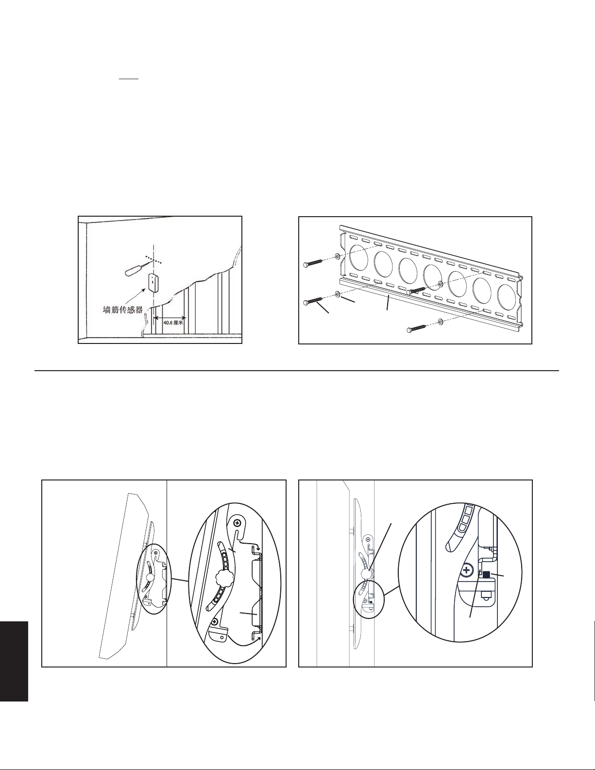
步骤 3:安装墙板:可安装于木立筋、砖、实体混凝土和混凝土砌块之上。
木立筋安装:
墙板 (a) 必须安装在两根间距超过 30.5 厘米的木立筋上。使用高品质墙筋传感器找到两根相邻墙筋的位置。建议用锥子或细
钉确定墙筋的位置(如图 3a 所示)。预先用 3/16 英寸钻头在每根墙筋的所需高度上钻出深度为 6.4 厘米 的孔。应确保这
些孔位于墙筋的中心区域且相互齐平。以墙板为样板在每根墙筋上分别标出第二个孔的位置。用 3/16 英寸 钻头在标记位置
钻出深度为 6.4 厘米 的孔。然后用四枚方头螺栓 (t) 和四片方头螺栓垫圈 (u) 将墙板安装到墙上。请确保墙板的安装方向正
确,墙板中间的平面紧贴墙面,方头螺栓则位于墙板中心的两边(如图 3b 所示)。
砖、实体混凝土和混凝土砌块安装:
将墙板 (a) 作为样板在墙上标出 6 个孔的位置。使外侧的孔尽可能靠近墙板的外缘。三个孔位于上行槽中,三个孔位于下行
槽中。应确保各孔齐平且孔间距在 15.2 厘米以上。使用 1/2 英寸 圬工钻头预先钻出这些孔(深度至少为 6.4 厘米。将膨胀
螺丝 (v) 分别插入这些孔中。请确保膨胀螺丝装入后与混凝土表面完全齐平,即使上面有一层石膏板或其它材料也是这样。
然后用六枚方头螺栓 (t) 和六片方头螺栓垫圈 (u) 把墙板安装到墙上。
图 3a 图 3b
u
t a
步骤 4:将显示器安装到墙板上并装上安全螺钉
警告:有些电视机需要两个人才能将其抬起!Sanus 对由此造成的人身伤害或产品损坏不复任何责任。
将电视机挂在墙板上:首先将显示器架 (b, c) 挂在墙板 (a) 的顶端,然后如图 4a 所示转动显示器架使其下端位于墙板底端之
下。将安全螺钉 (w) 插入显示器架底部的螺孔中,用内六角扳手 (x) 旋紧,将其置于墙板底部突片之后(如图 4b 所示)。最
后将显示器架上的旋钮调整至所需的绷紧度,现在您可以自由调整您的新平板电视机了。
图 4a 图 4b
旋钮
b,c
w
a
底部
突片
中文
 Loading...