

Page 1
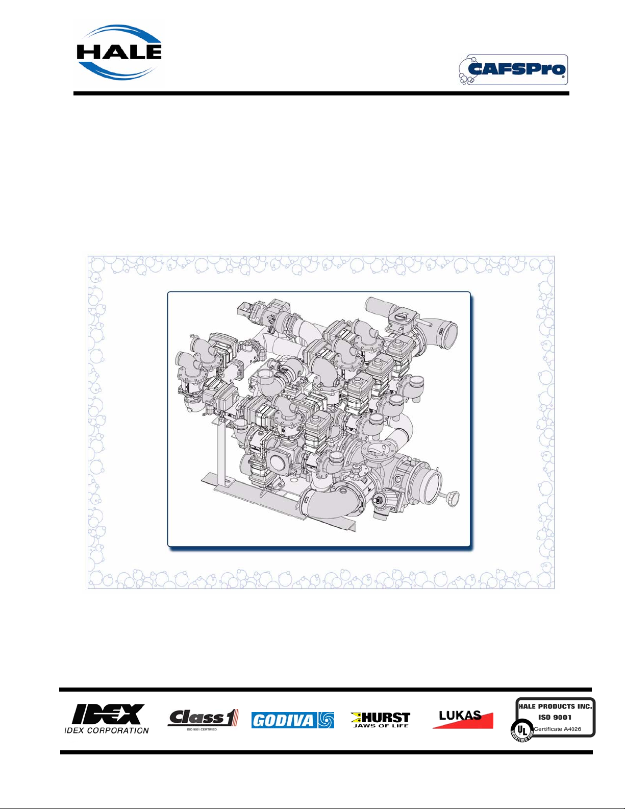
SMR-AC Addendum “A”
Compressed Air Foam System
CAFSPro
Hale Products Inc. ◆ A Unit of IDEX Corporation
700 Spring Mill Avenue
Telephone: 610-825-6300
Web............www.haleproducts.com
◆ Conshohocken, PA 19428 U.S.A.
◆ FAX: 610-825-6440
Manual p/n: 029-0020-78-0
Page 2
NOTICE !
Class1 cannot assume responsibility for product failure resulting from improper
maintenance or operation. Class1 is responsible only to the limits stated in the
product warranty. Product specifications contained in this manual are subject to
change without notice.
All Class1 products are quality components -- ruggedly designed, accurately
machined, precision inspected, carefully assembled and thoroughly tested. In
order to maintain the high quality of your unit, and to keep it in a ready condition, it
is important to follow the instructions on care and operation. Proper use and good
preventive maintenance will lengthen the life of your unit.
ALWAYS INCLUDE THE UNIT SERIAL NUMBER
IN YOUR CORRESPONDENCE.
ECO NO REV CHANGE FROM BY DATE APVD
0032 A INITIAL RELEASE LwH 07/29/2005 MAL
? B SMR-AC CAFSPro Addendum LwH 06/30-2006 MAL
HALE PRODUCTS, INC.
A Unit of IDEX Corporation
Conshohocken, PA 19428 USA
Manual p/n: 029-0020-78-0, Rev. -B
Printed in U.S.A.
DRAWN BY LwH ISSUE DATE COPYRIGHT ©
CHECKED BY PW 06/30/2005
NOT TO BE REPRODUCED OR USED TO
MAKE OTHER DRAWINGS OR MACHINERY.
© Hale Products, Inc. 2006
All Rights Reserved
Page 3

Addendum - Table of Contents ❑
Contents Page
SMR-AC CAFSPro Installation Addendum
Addendum: SMR-AC Installation........................................................................ 5
A.1 Unpacking........................................................................................................................... 5
Lifting the System ...............................................................................................................................5
Figure A-1: Lifting the SMR-AC system................................................................................6
A.2 SMR-AC System Mounting ................................................................................................ 6
SMR-AC CAFSPro Main Pump System Assembly.............................................................................6
Figure A-2: Shock Mounting .................................................................................................7
Oil Separator Tank Assembly .............................................................................................................7
Figure A-3: Separator Tank Mounting Bracket .....................................................................7
Panel Strainer, Water Cooling ............................................................................................................ 8
A.3 Plumbing Connections ......................................................................................................8
Figure A-4: Overview, SMR-AC System Connections (FRONT View) .................................8
Figure A-5: Overview, SMR-AC System Connections (REAR View)....................................9
A.4 Oil Separator Tank ............................................................................................................. 9
Figure A-6: Separator Tank Installation Overview ..............................................................10
Figure A-7: Depressurizing Valve Assembly ......................................................................11
A.5 Air Filter.............................................................................................................................12
Figure A-8: Typical Air Filter Installation.............................................................................12
A.6 Electrical Connections..................................................................................................... 12
Harness Connections ......................................................................................................................12
Table A-9: Harness Connections........................................................................................12
Addendum - SMR-AC CAFSPro Installation Guide
p/n: 029-0020-78-0
3
Page 4

❑ Addendum - Table of Contents
Contents - continued Page
Notes
_______________________________________________________________________
_______________________________________________________________________
_______________________________________________________________________
_______________________________________________________________________
_______________________________________________________________________
_______________________________________________________________________
_______________________________________________________________________
_______________________________________________________________________
_______________________________________________________________________
_______________________________________________________________________
_______________________________________________________________________
_______________________________________________________________________
_______________________________________________________________________
_______________________________________________________________________
_______________________________________________________________________
_______________________________________________________________________
_______________________________________________________________________
_______________________________________________________________________
_______________________________________________________________________
_______________________________________________________________________
_______________________________________________________________________
_______________________________________________________________________
_______________________________________________________________________
_______________________________________________________________________
_______________________________________________________________________
_______________________________________________________________________
_______________________________________________________________________
_______________________________________________________________________
_______________________________________________________________________
_______________________________________________________________________
_______________________________________________________________________
4
Addendum - SMR-AC CAFSPro Installation Guide
p/n: 029-0020-78-0
Page 5
SMR-AC Installation and Setup ❑
Addendum: SMR-AC Installation
This SMR-AC Installation Addendum is in addition to and is to be used in conjunction with the CAFSPro Installation Guide, Hale p/n: 029-0020-78-0. Additional
installation is required by the builder / installer as the Oil Separator Tank must be
externally mounted, requiring additional plumbing.
A.1 UNPACKING
The SMR-AC CAFSPro system is shipped primarily assembled on two
skids. One skid contains the main SMR-AC CAFSPro pump, manifold and
valve assembly. The second skid contains the FoamLogix Pump Unit, Air
Separator Tank, Gearbox, along with all supplied loose items.
Use care when removing the SMR-AC CAFSPro from its packaging (skid) to
prevent injury and/or damage to the system, especially the external system
connecitons.
IMPORTANT!
EXERCISE CARE DURING UNPACKING AND INSTALLATION TO PREVENT
INJURY AND/OR DAMAGE TO THE SYSTEM AND TO ENSURE THAT THE
IDENTIFICATION TAGS ARE NOT REMOVED BEFORE THE CONNECTIONS
ARE MADE.
DO NOT REMOVE OR ALTER ANY HYDRAULIC OR PNEUMATIC CONNECTIONS WITHOUT WRITTEN APPROVAL FROM HALE PRODUCTS. ALSO SEE
SECTION “1 SAFETY PRECAUTIONS” BEGINNING ON PAGE 7.
Lifting the System
WARNING !
THE SMR-AC CAFSPRO PUMP SYSTEM IS HEAVY AND BULKY, POSSIBLY
WEIGHING OVER 2,000 LBS. (907 KGS.). CHECK BILL OF LADING FOR
APPROXIMATE WEIGHT. USE PROPER LIFTING SUPPORT DEVICES (OVERHEAD CRANE, STRAPS/CHAINS, ETC.) CAPABLE OF HANDLING THE LOAD
WHEN MOVING OR INSTALLING THE SYSTEM.
DO NOT ATTACH LIFTING APPARATUS TO THE SYSTEM MANIFOLDING.
ATTACH DIRECTLY TO THE FRAME.
Addendum - SMR-AC CAFSPro Installation Guide
p/n: 029-0020-78-0
51
Page 6

❑ SMR-AC Installation and Setup
WARNING - continued !
PLACE A BRACE, APPROXIMATELY 3’ (1 METER) BETWEEN THE LIFTING
STRAPS / CHAINS TO PREVENT APPLYING EXCESSIVE PRESSURE TO THE
MANIFOLDS AS THE SYSTEM IS LIFTED INTO PLACE. APPLY A STRAP
AROUND THE FRONT SUCTION INLET AS SHOWN TO DEVELOP A THREEPOINT LIFT, MAKING SURE THE SYSTEM IS BALANCED. ALSO SEE FIGURE A-1: “LIFTING THE SMR-AC SYSTEM (THREE-POINT LIFT).”
Figure A-1: Lifting the SMR-AC System (Three-Point Lift)
A.2 SMR-AC SYSTEM MOUNTING
SMR-AC CAFSPro Main Pump System Assembly
When installing the SMR-AC CAFS System to the apparatus chassis, use
accepted practices for mounting. Review previous Section 3 “Receiving
and Inspection” beginning on page 13. Also see Figure A-2: “Shock Mounting” on page 53.
52
Addendum - SMR-AC CAFSPro Installation Guide
p/n: 029-0020-78-0
Page 7

SMR-AC Installation and Setup ❑
Whether mounting directly to the chassis, or constructing a separate bracket,
accepted brackets must be used.
Shock absorption is provided and must
be included in any mounting modification. (See Figure A-2: “Shock Mounting.”)
All mounting brackets must be constructed from structural angled steel,
having minimum dimensions of 4” x 36”
x 1/2” (102 x 914 x 13 mm). Use mini-
Figure A-2: Shock Mounting
mum 5/8”, Grade 8 bolts with flat
washers and lock nuts.
Installation diagrams are located at the back of this manual to assist with
overall dimensions and clearances required for the various mounting configurations. Also see Section “ Drawing Package” beginning on page 67.
Oil Separator Tank Assembly
Mount the oil separator tank assembly at a convenient and accessible location, enabling a clear view of the oil level sight gauge and oil fill cap. (See
Figure A-3: “Separator Tank Mounting Bracket.”).
Addendum - SMR-AC CAFSPro Installation Guide
p/n: 029-0020-78-0
Figure A-3: Separator Tank Mounting Bracket
53
Page 8

❑ SMR-AC Installation and Setup
Attach female eye-bolts, 12 mm, to the
top cross bracket mounting studs for
lifting. Mount the separator tank having the inlet port sightly BELOW the
compressor discharge port to ensure
back-flush does not enter the compressor, which would severely damage
the unit. (See Figure A-4: “Lifting Separator Tank.”)
Mount the tank using 7/16”-14, Grade
8 screws, flat and lock washers and
nuts. For a separator tank mounting
overview schematic, see Section
“Drawing Package” on page 67.
Figure A-4: Lifting Separator
Tan k
Panel Strainer, Water Cooling
For mounting instructions, see Section 4.4 “Panel Strainer” on page 21.
A.3 PLUMBING CONNECTIONS
(See Figure A-5: “Overview, SMR-AC System Connections,” on page 55.)
The following connections are made by the system builder/installer:
❑ Truck air to solenoid manifold
❑ Gearbox cooler return line to booster tank
❑ Pressure lines (3/8” tube) to PM control
❑ Control line (3/8” tube) from PM control to sensing valve
❑ Switch and truck air to pump master drain
❑ Water and air to duplex master gauge
❑ TRV electrical and discharge connections
❑ TPM electrical connections
54
Addendum - SMR-AC CAFSPro Installation Guide
p/n: 029-0020-78-0
Page 9

SMR-AC Installation and Setup ❑
Figure A-5: Over-
view, SMR-AC Sys-
tem Connections
Addendum - SMR-AC CAFSPro Installation Guide
p/n: 029-0020-78-0
55
Page 10

❑ SMR-AC Installation and Setup
A.4 OIL SEPARATOR TANK
For a general overview of the oil separator tank connection, see Section
“Drawing Package” on page 67. (See Figure A-6: “Separator Tank Installation Overview.”)
56
Figure A-6: Separator Tank Installation Overview
The following connections are made by the system builder/installer:
❑ (#1) Compressor discharge air / oil mixture to oil separator tank INLET.
Use 1-1/2” (38 mm), wire reinforced hose. For example, Aeroquip
FC350-24. (See Figure A-6: “Separator Tank Installation Overview.”)
❑ (#2) Oil separator tank DISCHARGE to CAFSPro manifold (air INLET).
Addendum - SMR-AC CAFSPro Installation Guide
p/n: 029-0020-78-0
Page 11

SMR-AC Installation and Setup ❑
Use 1-1/4” (32 mm), wire reinforced hose for maximum air flow. For
example, Aeroquip FC350-20.
Note: Two check valves are provided in this discharge line to ensure water is not
back-flushed into the oil separator tank.
❑ (#3) Oil separator tank DISCHARGE to heat exchanger.
Use 7/8” (22 mm), wire reinforced hose. For example, Aeroquip FC350-
16. (See Figure A-6: “Separator Tank Installation Overview,” on page
56.)
❑ (#4) Air sensing valve to duplex gauge.
Use DOT approved red 1/4” (6 mm) tubing
❑ (#5) Oil separator tank to compressor control line.
Provided - 3/8” (10 mm), wire reinforced high pressure hose. For example, Aeroquip FC332-06.
❑ (#6) Oil separator
tank “discharge”
air feed to air filter
line (blow-down
line). (See Figure
A-7: “Depressurizing Valve Assembly.”)
Use DOT
approved low
pressure tubing
(1/4” / 6 mm).
❑ (#7) Oil separator
tank to compressor, oil scavenge
line. Use DOT
approved air supply tubing. (See
Figure A-7: Depressurizing Valve Assembly
Figure A-6: “Separator Tank Installation Overview,” on page 56.)
❑ Oil / water separator tank drain and shut-off vavle.
❑ An auxiliary air outlet for rescue tools and testing is provided. A fitting is
available, with JIC cap, on the outlet of the separator tank.
Remove the protective cap, and install an appropriate hose. Use 3/4”
(19 mm) to 1” (25.4 mm), wire reinforced hose for maximum air flow. For
example, Aeroquip FC350-16, 1” (25.4 mm) wire reinforced hose.
A quick disconnect and ball valve should be installed on the panel, as
required.
Addendum - SMR-AC CAFSPro Installation Guide
p/n: 029-0020-78-0
57
Page 12

❑ SMR-AC Installation and Setup
Note: A minimum 1” (25.4 mm) connection is required to test the system per
NFPA standards.
A.5 AIR FILTER
For reliable operation, the CAFS air filter must be located in a clean, freshair environment, usually in the dunnage area above the pump compartment.
DO NOT damage the filter during
assembly and be sure the mounting area offers protection.
Mount the air filter 6” (152 mm)
MINIMUM above the decking platform to prevent standing water from
being sucked into the filter and possibly back into the system. (See
Figure A-8: “Typical Air Filter Installation,” on page 58.)
Use 3” (76.2 mm) CPVC pipe and
rubber connections. Support the
piping with brackets as needed.
Figure A-8: Typical Air Filter Installation
A.6 ELECTRICAL CONNECTIONS
Harness Connections
To From
Separator Tank Air Sensing Valve C14
Vent Valve C7
Oil temperature Sensor C15
Oil Salvage (Blow-Down) C17
Gearbox Pump Engaged Switch C9
Tachometer Sender C13
Labeled Apparatus Power C16
Connector
Number
58
Table A-9: Harness Connections
Addendum - SMR-AC CAFSPro Installation Guide
p/n: 029-0020-78-0
Page 13

(See Figure A-6: “Separator Tank Installation Overview,” on page 56.) Also
see Figure A-7: “Depressurizing Valve Assembly” on page 57.
A.7 FLUID LEVELS
To meet various shipping regulations, oil within the pump gearbox and separator tank assemblies is drained prior to shipping from the factory.
AT INSTALLATION AND BEFORE OPERATION, ALL FLUIDS MUST BE ADDED
TO THE APPROPRIATE LEVELS.
Before operation, refill and check as necessary -
SMR-AC Installation and Setup ❑
IMPORTANT !
❑ Separator tank - see page 35.
❑ Hot shift clutch option - see page 36.
❑ Pump gearbox reservoir - see separate pump service manual.
Addendum - SMR-AC CAFSPro Installation Guide
p/n: 029-0020-78-0
59
Page 14

❑ SMR-AC Installation and Setup
Notes
______________________________________________________________________
______________________________________________________________________
______________________________________________________________________
______________________________________________________________________
______________________________________________________________________
______________________________________________________________________
______________________________________________________________________
______________________________________________________________________
______________________________________________________________________
______________________________________________________________________
______________________________________________________________________
______________________________________________________________________
______________________________________________________________________
______________________________________________________________________
______________________________________________________________________
______________________________________________________________________
______________________________________________________________________
______________________________________________________________________
______________________________________________________________________
______________________________________________________________________
______________________________________________________________________
______________________________________________________________________
______________________________________________________________________
______________________________________________________________________
______________________________________________________________________
______________________________________________________________________
______________________________________________________________________
______________________________________________________________________
______________________________________________________________________
______________________________________________________________________
______________________________________________________________________
______________________________________________________________________
______________________________________________________________________
______________________________________________________________________
60
Addendum - SMR-AC CAFSPro Installation Guide
p/n: 029-0020-78-0
 Loading...