

02/10/2004
PART 1: MAINTENANCE INSTRUCTIONS
SMR-U
Stainless Steel Rear Mount Pump
DESCRIPTION AND MAINTENANCE MANUAL
PRELIMINARY
Hale SMR Pump Serial Number:____________________________________
All Hale products are quality components: ruggedly designed, accurately machined, precision inspected, carefully assembled
and thoroughly tested. In order to maintain the high quality of your unit, and to keep it in a ready condition, it is important to
follow the instructions on care and operation. Proper use and good preventive maintenance will lengthen the life of your unit.
ALWAYS INCLUDE THE UNIT SERIAL NUMBER IN CORRESPONDENCE.
HALE PRODUCTS, INC. z A Unit of IDEX Corporation z 700 Spring Mill Avenue z Conshohocken, PA 19428 z TEL: 610-825-6300 z FAX: 610-825-6440
MANUAL P/N 029-0020-77-0, REV 1, © 2004 HALE PRODUCTS, INC., PRINTED IN U.S.A.
Hale Products cannot assume responsibility for product failure resulting from improper
maintenance or operation. Hale Products is responsible only to the limits stated in the product
warranty. Product specifications contained in this material are subject to change without notice.

NOMINAL PERFORMANCE
Model WSA2010 Aluminium
Nominal output 2000 l/min at 10 Bar & 3m lift
Model WSB2010 Bronze
Model WSA3010 Aluminium
Nominal output 3000 l/min at 10 Bar & 3m lift
Model WSB3010 Bronze
Model WSA4010 Aluminium
Nominal output 4000 l/min at 10 Bar & 3m lift
Model WSB4010 Bronze
RECOMMENDED SPARES
Thank you for choosing the GODIVA Fire Pump – designed and built to provide
many years of trouble-free service.
Whilst we consider that it is the best fire pump available today, we also recognise
that any ‘rotating machinery’ is subject to wear and therefore recommend that you
request our 2 years’ Recommended Spares Listing.
This stock holding will enable you to maintain the pump in cases where minor
defects occur and minimise any possibility of your pump being ‘off-the-run’ for
extended periods.
©Godiva, Warwick
September 2000
wsmaint-Issue2 25-9-02
2

CONTENTS
SECTION PAGE
SAFETY-RELEVANT DATA 4
GENERAL DESCRIPTION 5
LUBRICATION 6
PROTECTION AGAINST FROST 7
SECTION: 1 SUCTION TUBE & FRONT WEARING RING 8
2 WEARING RING MAINTENANCE 8
3 LOW PRESSURE IMPELLER & 9
REAR WEAR RING
4 CARBON SEAL & SEATING ASSEMBLY 11
5 VOLUTE BODY 13
6 LOW PRESSURE MANIFOLD 14
7 PRIMING SYSTEM 15
8 PUMP BODY 17
9 FRONT END OIL SEAL & WEAR RING 17
10 REAR END OIL SEAL & WEAR RING 19
11 BEARING HOUSING 20
12 PUMP TESTS 21
13 DELIVERY VALVES 22
©Godiva, Warwick
September 2000
wsmaint-Issue2 25-9-02
3

SAFETY-RELEVANT DATA
for VEHICLE BUILDER/INSTALLER
Thank you for purchasing a Godiva Pump.
Vehicle Manufacturers will find full details regarding installation in the
relevant section of this manual.
A risk assessment of the Vehicle Pump Range has been conducted in line with the
Machinery Directive 89/392/EEC, with the following results:
INSTALLATION
The pump MUST BE SECURELY INSTALLED to the vehicle chassis.
MAINTENANCE
It is the responsibility of the user to ensure that the equipment is maintained in a safe operational condition, as per regulation 5 in the Provision and Use of Work Equipment Regulations 1998.
PUMP DRIVE AND PRIMING SYSTEMS
A guard is available to enclose the priming system drive if this is deemed necessary.
The vehicle-mounted pump is NOT a machine (see Declaration of Incorporation) and
the guarding of this area together with the drive system of the pump MUST BE
CONSIDERED by the Vehicle Builder when incorporating the pump into HIS
machine.
NOISE
The manufacturer of the machine into which the pump is incorporated MUST
INDICATE any protective equipment that may be required. Test data may be
sourced from Godiva where required.
THERMAL RELIEF VALVE
The WS Series single pressure pump can be fitted with an optional THERMAL
RELIEF VALVE which is fitted to assist in the prevention of over heating which could
occur through incorrect operation of the pump, ie running the pump at high speed
with all the discharge valves closed.
OPERATION
When installed into a fire-fighting appliance, TRAINED PERSONNEL must operate
these pumps ONLY.
Engineering Director
1 July 1998
F W Mason
©Godiva, Warwick
September 2000
wsmaint-Issue2 25-9-02
4

GENERAL DESCRIPTION
The Godiva WS series single stge pump is a single pressure pump. It delivers
high volume, low pressure (LP) output water.
The pump is generally driven in a clockwise direction viewed from the drive end. The
pump may also be specified configured to rotate in a counter-clockwise direction.
The pump drive shaft, which runs on angular contact and roller bearings in an oil
bath, is of stainless steel. Shaft sealing of the pump is by a special Godiva
mechanical seal face, which ensures efficiency and long life without adjustment. The
electronic tachometer sender is mounted adjacent to the drive flange.
Priming of the pump is achieved automatically by means of a pair of positive
displacement piston primers mounted on either side of the bearing housing. These
primers begin to operate as soon as the pump drive shaft begins to rotate, driven by
an eccentric bearing on the pump shaft. Air within the pump will be expelled and as
long as the suction connections have been made and the hose end submerged, the
pump will prime and the pistons will disengage by 1.5 bar. The pump should be
primed at any speed between 1000-2500 rpm. The pump speed should not be
increased further until the primers have disengaged and the pump is primed.
An optional alternative priming system – the Godiva water ring primer – is available
in place of the piston primer system. With the water ring primer, when the pump is
started, the primer shaft is driven by its fibre driving wheel which contacts the pulley
on the pump drive shaft and is lifted off by a disengaging cylinder as the pump is
primed and pressure builds up in the pump. An alternative to friction pulley drive is
belt-drive through an electro-magnetic clutch. When the pump is primed and
pressure builds up, a pressure switch turns off the clutch drive.
Non-return valves are built into both the piston and water ring priming systems to
prevent air flowing back through the primers, thus “breaking the prime”.
As the pump is reduced to idling and the pressure within the pump decreases, the
pistons will once again reengage to act as a pump and discharge any water
remaining in the pump.
A World Series Options Manual is available which shows many of the standard
specifications currently available together with an indication of their positions relative
to datum points on the pump.
©Godiva, Warwick
September 2000
wsmaint-Issue2 25-9-02
5
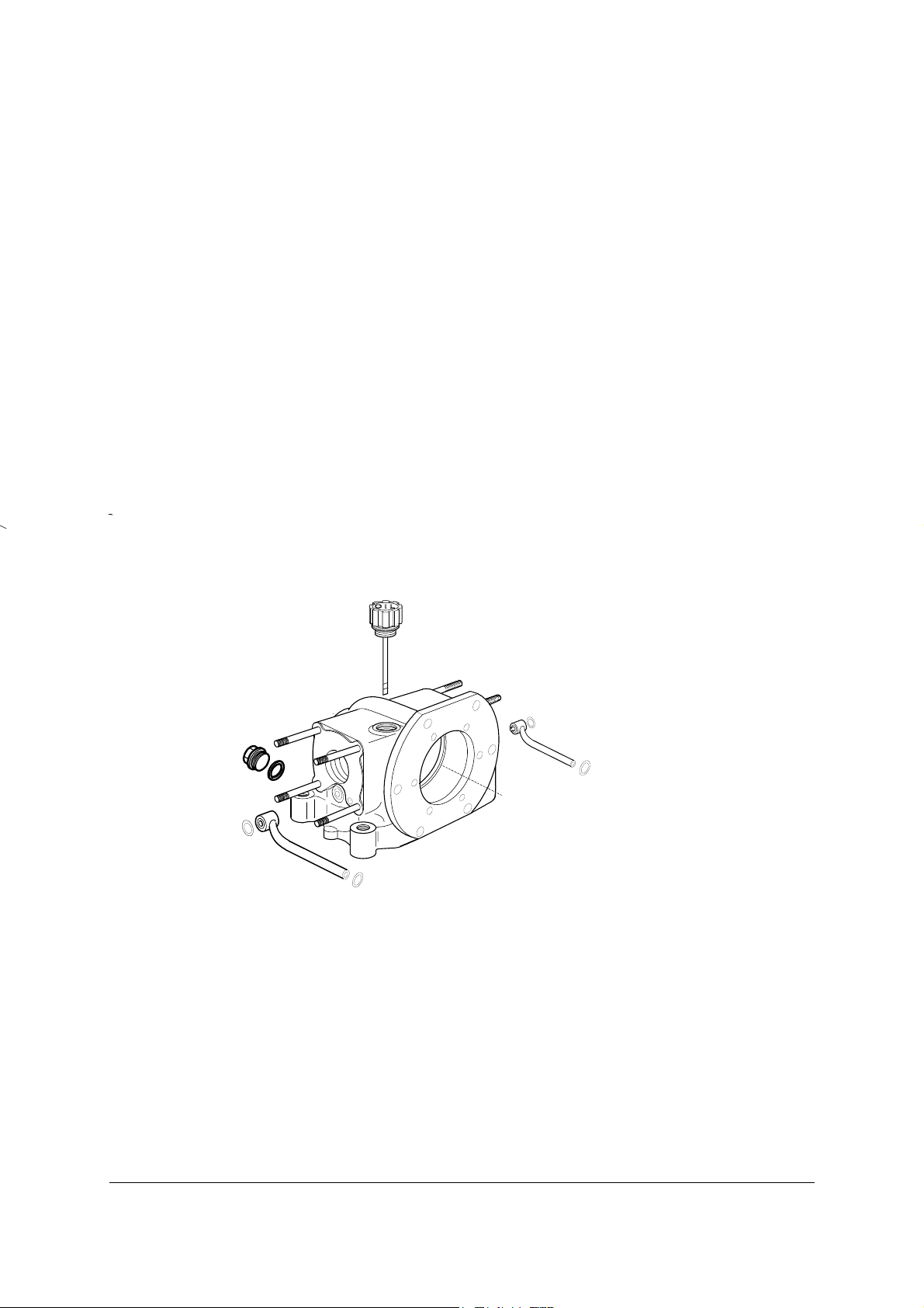
LUBRICATION
The oil bath provided for the pump drive shaft bearings has a capacity of 0.75 litres
(1.3 pints) and should be topped up when necessary with 10w/40-15w/40 multigrade
engine oil. It is recommended that the oil bath is drained and refilled with fresh oil
about every twelve months.
To check the oil level, remove the filler/dipstick, which is situated on the bearing
housing immediately behind the pump body. Add fresh oil through the oil filler
aperture until it reaches the dipstick level. Refit the oil filler plug securely. Run the
pump for a short period and then re-check the oil level. The oil level should be
checked with the dipstick screwed down into its fixed position.
The oil drain plug is situated at the rear of the bearing housing below the pump drive
flange as shown on Fig 1-1.
Fig 1-1 Bearing housing oil filler, level and drain plug
©Godiva, Warwick
September 2000
wsmaint-Issue2 25-9-02
6

PROTECTION AGAINST FROST
As a precautionary measure, when frost is anticipated, drain all water from the pump
and its ancillaries.
Removing the drain plug from the base of the volute drains the pump. If the primer
exhaust is piped away to above the primer outlets, these must be provided with drain
valves.
If the water ring primer is fitted, removing the drain plug at the base of the water trap
housing drains it.
IMPORTANT: It is essential to carry out the pump tests detailed in Section 13
whenever any part of the pump or priming system is dismantled.
This will ensure that reassembly has been carried out correctly
and that there are no leaks.
©Godiva, Warwick
September 2000
wsmaint-Issue2 25-9-02
7

Section 1
SUCTION TUBE AND FRONT WEARING RING
To Remove
To remove the suction tube, remove priming pipe and foam inductor (if fitted) from
RH side, and Tank Fill line (if fitted) from LH side of suction tube. Remove the M10
nuts, spring washers and plain washers to allow the withdrawal of suction tube and
front wearing ring if necessary. The front wearing ring has two identical O rings, one
of which is face mounted towards suction tube and the second being in a groove
behind its flange.
To Refit
Clean all flange faces and lightly grease new O rings before refitting.
Check the large internal diameter of the wearing ring in several places (see Fig 2-1).
If it exceeds dimension ‘A’ 140.60 mm (5.535 in) for WS 2010 and WS 3010 model
pumps, or 171.00 mm (6.732in) for WS 4010 models, at any point, the wearing ring
must be renewed.
Fig. 2-1
To Refit
Refitting is a reversal of the removal instructions. Use new O rings lightly greased
before refitting and should be fitted with diameter A towards the impeller.
Section 2
WEARING RING MAINTENANCE
A
©Godiva, Warwick
September 2000
wsmaint-Issue2 25-9-02
8
A
SECTION 3
LOW PRESSURE IMPELLER AND REAR WEAR RING
To Remove
In order to access the low pressure impeller, it is only necessary to disconnect
pipework as described in Section 1, then remove the 12 off M12 bolts from the volute
cover plate which may then be withdrawn together with suction tube etc giving direct
access to the low pressure impeller leaving the volute body in situ. Remove the
tacho sender and fit shaft locking screw (Tool No 60275/11) locating the spigot into
one of the drive flange holes. Remove the impeller nut and the pair of lock washers
and withdraw the impeller from the keyed pump shaft. It may be necessary to use
special tool 60275/04 to remove the impeller from the pump shaft.
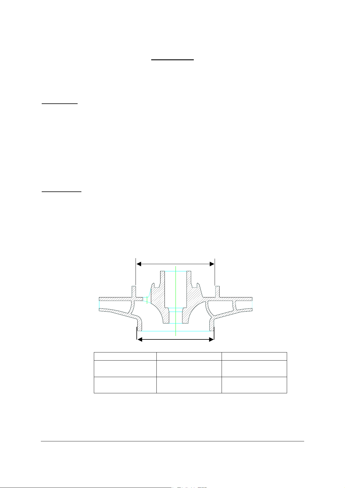
Maintenance
Check the wearing diameter on the impeller in several places (see Fig 3-1). If the
diameter is less than stated in the table below, a new impeller should be fitted.
Fig 3-1 Checking the wearing diameters of the low pressure impeller
B
Pump Type Front Diameter (A) Rear Diameter (B)
WS2010 and
WS 3010
WS4010
139.319 mm
5.485 in
169.67 mm
6.680 in
135.33 mm
5.238 in
170.56 mm
6.715 in
©Godiva, Warwick
September 2000
wsmaint-Issue2 25-9-02
9
To Refit
Refitting is a reversal of the removal instructions. It is recommended that new O
rings are fitted to impeller end face and shaft and a new pair of lockwashers are
fitted before refitting the impeller nut which should be tightened to 400Nm (295 lbs ft)
torque. To refit front cover plate, a new O ring should be fitted to the cover plate
spigot before assembly.
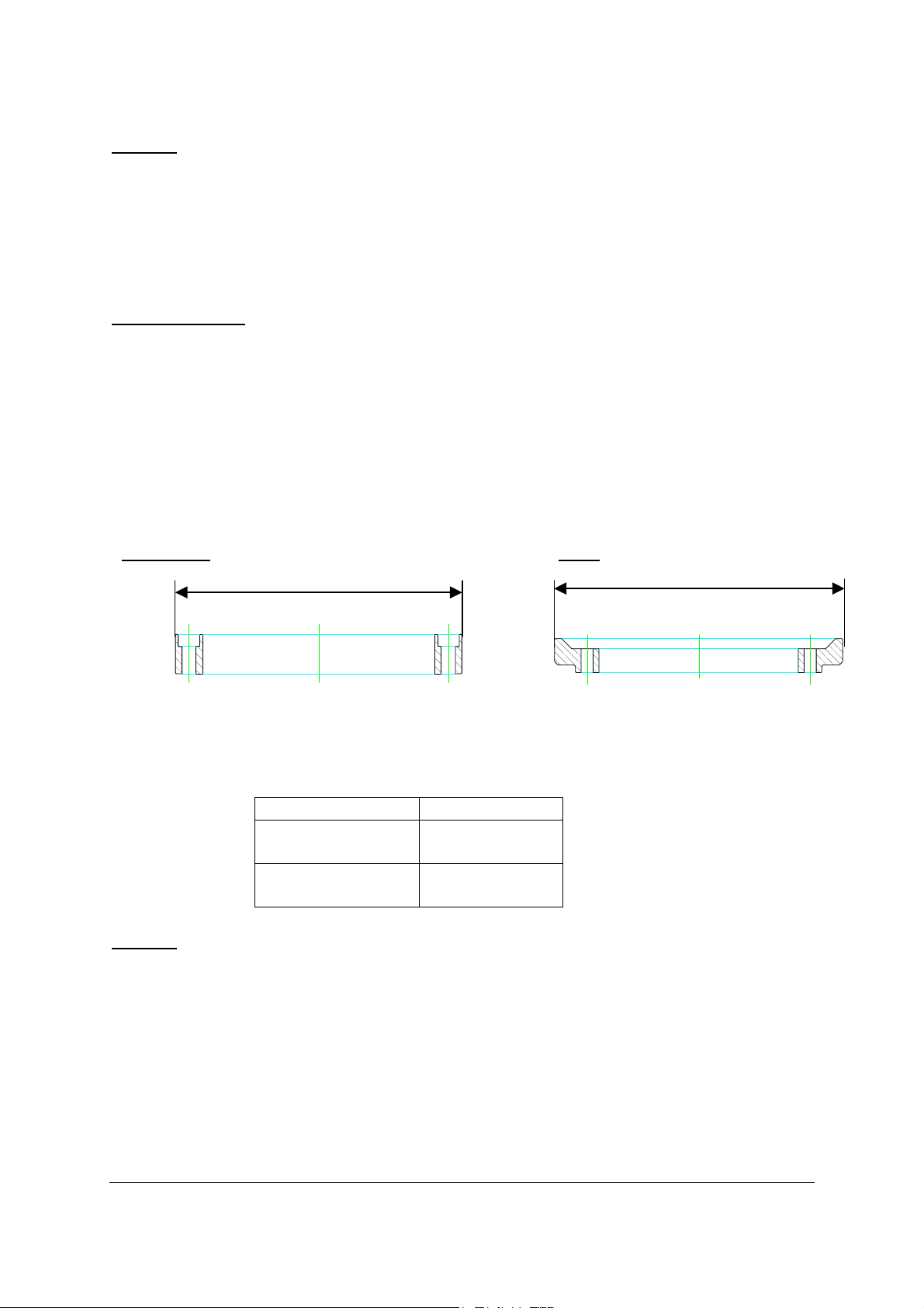
Rear Wear Ring
The rear wear ring (accessible after the removal of the low pressure impeller) is
retained by 4 off M8 socket head screws. After removal of these screws, the rear
wear ring may be jacked out by means of two screws inserted into the adjacent
tappings.
Checking the wearing diameters of rear wear ring
2010/3010
X 4010 X
Pump Type Dia X
WS2010 and
134.12mm
WS 3010
WS4010
169.62mm
To Refit
Clean all surfaces before re-assembly. Apply Loctite 242 to screw threads before
refitting and tightening.
©Godiva, Warwick
September 2000
wsmaint-Issue2 25-9-02
10

Section 4
CARBON SEAL AND SEATING ASSEMBLY
When the impeller is removed, the mechanical carbon face seal is accessible for
examination. In the event of excessive leakage past the carbon seal and out of the
drain hole in the pump head, remove impeller per Sections 3. Examine the carbon
seal. If the face of the carbon seal-seating ring is scored, it is essential to replace it
and to fit a new seating ring, which is mounted within the rear face of the impeller.
To remove the carbon seal seating ring, remove two M6 nyloc nuts and washers and
gently remove it, taking care not to lose the wave spring. The stationary carrier may
be left in place if only the wearing faces are being replaced.
The silicon carbide ring fitted in the rear side of the low pressure impeller may be
levered out, by means of a small instrument screwdriver inserted between the ring
and its rubber cup.
Re-assembly of the seal is completed as described below. Please note: Mechanical Seals are precision-engineered devices and extreme care must be taken to ensure that no damage occurs to the lapped faces.
Read the fitting instructions before installation of the seal.
Ensure that the lapped faces are absolutely clean throughout the entire installation.
Soiled faces must to be cleaned with appropriate degreasing cleaner
and soft tissue.
©Godiva, Warwick
September 2000
wsmaint-Issue2 25-9-02
11

B
G
F
E
C
D
H
I
A
1. Ensure that the Pump Body (A) and Impeller (B) bores are clean and free from
burrs and sharp edges.
2. Lubricate the O Ring (C) with a suitable lubricant and carefully assemble the
Seal Head Assembly (D) into the Pump Body (A), lining up the cut-outs in the
Seal Head Assembly (D) with the threaded Studs (E).
3. Fit Washer (F) to each of the Studs (E) followed by the Lock Nuts (G). The lock
nuts should be tightened half a turn at a time so that the Seal Head Assembly
(D) is pulled squarely into the Pump Body. Ensure that the Lock Nuts are fully
secured.
4. Ensure Carbon Face (H) is clean and free from grease, if not use a degreasing
cleaner and soft tissue. Apply clean water to the carbon face.
5. Take Impeller (B) and carefully push the Mating Ring Assembly (I) into the bore
using Fitting Tool Number 60275/08. Ensure that the Face of the Mating Ring
Assembly is fitted squarely in the impeller housing within 0.1mm.
6. Carefully fit the Low Pressure Impeller onto the shaft and continue with pump
build.
©Godiva, Warwick
September 2000
wsmaint-Issue2 25-9-02
12

Section 5
VOLUTE BODY
It is extremely unlikely in normal servicing that the volute body will require to be
removed, but in the event of removal the front cover plate should be removed as in
Section 3. The volute is mounted on to the pump body by means of twelve studs,
nuts and washers. The seal at both front and rear faces of the volute is by O ring
seals, which should be replaced if the joint face is disturbed. This volute may be
mounted on either standard rotation pumps or reverse rotation pumps, and must be
fitted the correct way round (see the cast on arrow near to the manifold connecting
face, normally on the right hand side). The 12-mounting studs should always face
the rear of the pump.
©Godiva, Warwick
September 2000
wsmaint-Issue2 25-9-02
13

Section 6
LOW PRESSURE MANIFOLD AND FILTER HOUSING
To Remove
Assuming that the gauge, thermal relief and foam connections have been
disconnected, it is necessary to remove the primer discharge pipe from the filter
housing to the pump body. Remove 8 off M8 bolts to remove the filter body. The
low pressure manifold is connected to the volute body by means of 4 off M10 bolts
surrounding the thermal relief valve and 2 M10 stainless steel socket head cap
screws inside the manifold casing (these 2 screws are fitted with bonded seals to
prevent leakage). The manifold may now be removed. The gasket between the
manifold and the filter housing will require renewal at this stage. The seal between
the volute body and manifold is an O ring.
The main outlets to the manifold (6 off) are sealed by means of O rings, seated in
grooves in the manifold faces.
Reassembly
When reassembling the manifold, all O rings should be replaced and Loctite 242
should be applied to all threads before refitting.
Filter Housing
The housing contains the primer disengagement filter, accessible from the front
panel area. This filter however, must not be removed whilst the pump is in
operation.
The flow across the filter is from outside to inside the cylindrical profile. The filter is
intended to restrict particle size in water entering the primer disengaging circuit.
©Godiva, Warwick
September 2000
wsmaint-Issue2 25-9-02
14

Section 7
PRIMING SYSTEMS
POSITIVE DISPLACEMENT PISTON PRIMERS
To Remove End Covers
Access to each identical primer, mounted on each side of the bearing housing, is as
follows:
The primer end cover contains a priming valve and inlet and outlet valves and is
removed by the removal of 4 nuts and washers (see Fig 8-1).
Servicing of this cover is as follows
Priming valve
Inlet seal,
Orifice plate
Outlet seal
Primer end cover
Cylinder
assembly
Fig 8-1 Piston Primer
After removal of a single central M8 socket cap screw, the inlet seal, orifice plate and
outlet seal may be removed. Replacement or reassembly may follow after applying
Loctite 262 to the screw thread. Note this screw must be tightened to ensure that
the rubber seal is compressed until metal to metal resistance is achieved.
The priming valve mounted above may be stripped as follows – remove the 4 M6
bolts (and washers) which pass through the end cover into the inlet casting (which
contains an O ring in the bore) and an O ring face seal to the end cover.
The outer end cap clamps on to a rubber diaphragm against the main cover. The
priming valve now revealed has a single socket screw and Nyloc nut to constrain its
components.
©Godiva, Warwick
September 2000
wsmaint-Issue2 25-9-02
15

Priming valve
diaphragm
Fig 8-2 Priming End Cap
Assembly
On re-assembly, a new diaphragm, seal washer and
O rings should be fitted without exception and care
should be taken to ensure that the vent hole in the
end cap is clear and towards the base of the unit.
All components must be clean and dry before
reassembly.
To remove primer cylinders, these are retained by 2
special nuts mounted diagonally on cylinder
assembly and may then be withdrawn (care should
be taken to prevent bearing housing oil leakage or
contamination, if the cylinders are withdrawn).
Extreme care is required if the primer cylinder
assembly is to be stripped, because of the strong
return spring. It is strongly recommended that Tool
No PSK2956 and 57437 are used for disassembly
and reassembly of the cylinder assembly.
Cylinder disassembly
(see Fig 8-2)
Locate and clamp flats on piston rod end. Depress and hold cylinder at least on mid
stroke, remove centre socket head screw and carefully release spring pressure
acting on underside of cylinder. Remove piston rod and spring. To remove piston
from cylinder bore, fit seal spreader Tool No 57437 to piston rod and reengage
piston rod (less spring) to push piston from cylinder bore. If piston rings are worn or
scored, both the piston ring and its O rings must be replaced before reassembly.
Piston
Spring
Piston rod seal
components
Fig 8-3 Primer piston cylinder
©Godiva, Warwick
September 2000
wsmaint-Issue2 25-9-02
16

Beneath the piston in the cylinder bore are 4 socket head screws retaining an end
cap which in turn retains an O ring, a metal sleeve with an internal 2 piece glyd ring
and a variseal in the bottom of the bore. If these components are withdrawn, the
seals should be renewed before assembly.
Careful examination of the cylinder bore and piston rod should be carried out and if
any serious scoring or wear has taken place, should be replaced. The thrust face on
the end of the piston rod is not serviced separately. The piston rod slides in
composition bearings mounted in the cylinder stem and it is extremely unlikely that
these bearings will need to be replaced.
Reassembly
Assuming all components have been cleaned, carefully insert the variseal, using
special Tool No PSK2880 into the cylinder (grooved side down) into the inner recess,
followed by the metal sleeve (cross hole must align with the drain hole in the
cylinder), plain end towards the variseal. This sleeve has a recess to accept the 2piece glyde ring, the inner component being a PTFE sleeve. Around the outside
diameter of the metal sleeve is fitted an O ring. The whole internal assembly should
be approximately flush with the seating for the end cap, which is retained by 4 small
socket head screws, which should be retained using Loctite 262 on the screw
threads. Piston seals, if replaced, should be fitted with the O ring first followed by
the PTFE sleeve, which must be gently stretched over the piston and into the groove
progressively. It is recommended that Tool No PSK2956 and 57437 should be used
for reassembly of the piston to cylinder, and all parts must be cleaned. Apply a
smear of engine oil to the piston rod. Locate the flats of the piston rod, fit the spring
carrier and spring. Place Tool 57437 on to the rod spigot and offer the cylinder
assembly over the piston rod.
Using tool PSK2956, compress the spring with the cylinder assembly, carefully
passing the piston rod through the cylinder seals until the shoulder on the rod is well
clear of the clamp plate in the bottom of the cylinder clamp (and remove the seal
spreading Tool 57437) to hold the cylinder in this position whilst the piston is inserted
into the cylinder bore and seats on to the piston rod spigot. Before inserting the
centre retaining screw, apply Loctite 601 to the screw threads and Loctite 510 under
the screw head. Insert and tighten the screw into the piston rod. The piston and
cylinder assembly may now be safely removed from the assembly fixture.
An O ring oil seal is fitted to the location diameter on the cylinder which should also
be renewed before installation to the bearing housing, together with an O ring in the
face of the feed tube which contacts the lower rear face of the cylinder.
©Godiva, Warwick
September 2000
wsmaint-Issue2 25-9-02
17

Supplement for World Series Pump Maintenance – WT and WS Models
Mk 3 Piston Primer (One piece piston) fitted to -
WT Models from Serial number 2000
WS Models from Serial number 9000
Disassembly/Assembly instructions for the piston assembly, part number 56960/06.
1. The piston assembly fitted to these models is a one-piece unit which is held in position by the
return spring. A spring retainer and a pair of split collets retain the spring against the end of
the piston rod.
2. To release the piston from the cylinder it is necessary to depress the spring retainer and the
spring below, but not the piston rod, this will then release the pair of split collets securing the
spring retainer.
A special tool is available from Hale Products Europe to assist with this procedure.
Reassembly of the piston to the cylinder is a reversal of the disassembly procedure.
Maintenance of the piston rod seal components is the same for both types of the piston primer.
Press on the spring retainer to release the split collets and the
spring below. When the spring is removed the piston can be
pushed from the cylinder
Spring retainer
Split collets
Spring
One-piece piston
©Godiva, Warwick
September 2000
wsmaint-Issue2 25-9-02
18

PRIMING SYSTEMS Continued
WATER RING PRIMER
The Water Ring Primer is available as an alternative to the Piston Primer system. It
is mounted above the bearing housing and driven by a fibre wheel in contact with a
pulley at the end of the main pump shaft. Operation of the Water Ring Primer is fully
automatic, when the pump is started the primer is driven by the pulley wheel turning
the fibre wheel, air is evacuated from the pump allowing water to enter and build
water pressure inside the volute. The water pressure inside the pump is then used,
via the redundant piston primer housing, to act on a lever which pivots, and through
a second lever, lifts the Water Ring Primer clear of the drive pulley on the pump
shaft. When the primer disengages from the pulley it stops operating, if the pump
pressure falls e.g. when the pump is turned off, the primer fibre wheel will re-engage
with the pulley ready for priming operation when the pump is started again.
To Remove
To remove the entire Water Ring Primer unit, slacken the hose clip retaining the
3/4inch hose to the top of the primer. Disconnect the hose and secure the hose end
away from the primer. Disconnect and remove the primer return spring from the
lower part of the primer. If connected, remove the air outlet connection from the top
and the water inlet connection from the bottom of the primer. Slacken the two grub
screws securing the primer to the hinge pin. Carefully ease the primer unit off the
primer hinge pin.
Maintenance
To dismantle the primer for internal inspection, remove the 10 bolts and washers
securing the primer bearing housing to the primer body. Remove the primer bearing
housing complete with shaft, bearings, impeller and pulley. Examine the inner
diameter of the impeller and the corresponding surface of the suction and delivery
cover for excessive scoring, renewing these parts if necessary.
To fit a new suction and delivery cover, remove the self-locking screws which secure
the cover plate to the suction and delivery cover. Fit this cover plate to the new part,
noting that no gasket is used but jointing compound should be used on the
contacting faces.
To fit a new impeller, undo the impeller retaining screw and pull off the impeller.
Note: if the impeller binds on the shaft it will be necessary to remove the primer shaft
as follows At the pulley end of the shaft, knock back the tabwasher and remove the nut
securing the pulley to the shaft. Remove the pulley and extract the woodruff key and
the circlip. Tap out the shaft from the impeller end. The shaft will bring the bearing
with it and these can now be replaced if necessary. The shaft seal will remain in
position and if this requires renewing it should be drifted out, together with its
backing washer, towards the impeller end. When fitting a new seal ensure that the
lip on the backing washer and the open end of the seal face is towards the impeller.
©Godiva, Warwick
September 2000
wsmaint-Issue2 25-9-02
19

To fit a new friction drive pulley, remove the pulley from the shaft as detailed above,
undo the four nuts, bolts and washers securing the pulley to the centre piece. Fit the
new pulley. Refitting of the pulley assembly is a reversal of the dismantling
instructions. Ensure that a new tab washer is always used on re-assembly.
To examine the non-return valve on top of the primer, undo the four bolts and
washers retaining the priming valve inlet to the valve body and cover. Examine the
seals, spring and diaphragm for wear, if necessary replace these parts.
To Refit
When refitting the water ring primer, rotate the primer hinge pin from its original
position so that the two grubscrews will bear on a different part of the shaft. Move the
whole primer forwards or backwards until both sides of the primer fibre wheel bear
equally on the sides of the driving pulley on the pump shaft. Tighten the grubscrews
and the associated locknuts. Reconnect the hoses to the relevant points and refit the
primer return spring.
When the primer is in position it is important to set a 3m gap between the bottom of
the lift-off pad attached to the primer and the lift-off rod which is used to lift the primer
away from the drive pulley. The gap is to make allowances for a new fibre drive
wheel to “bed-in” through initial wear, but still maintain sufficient distance to allow the
lift-off mechanism to work correctly. The lift-off pad can be turned to move it up or
down as required.
Primer non-return
valve
Air outlet
Fibre drive wheel
Pulley on pump
shaft
Water inlet
connection
Primer disengaging
mechanism
Piston primer blank cap
Primer hinge pin
Grubscrews to
secure primer to
hinge pin
Primer return
spring
3mm gap between
primer lift-off pad and
primer disengaging
lever
©Godiva, Warwick
September 2000
wsmaint-Issue2 25-9-02
20

Section 8
PUMP BODY
To Remove
Remove the low-pressure manifold, volute body and impeller (Sections 3,5 and 6)
and remove the carbon seal assembly (Section 5). Unscrew the six nuts and spring
washers securing the pump body to the bearing housing. Using a hide faced
hammer, progressively tap around the pump body until it is separated from the
bearing housing, taking care to withdraw the pump body from the two primer feed
tubes at approximately the 4 and 8 o’clock positions.
Normally, the only reason to remove the pump head would be to gain access to the
front oil seal mount on the bearing housing.
To Refit
When refitting, clean the mating faces of the bearing housing assembly and pump
head, ensuring that they are not damaged. Fit new O rings in the two primer feed
tube bores (one or both of these bores may be sealed with special screws if no
priming or other types of primer are used).
Carefully offer up the pump body to align with the feed connections and the six
threaded studs, refit spring washers and nuts to secure. Replacement of the
remainder of components is covered in the sections mentioned above.
Section 9
FRONT END OIL SEAL AND WEAR RING
To gain access to the front-end oil seal, it is necessary to remove pump head
(Section 9) and other relevant sections. Drain bearing housing oil by removing the
drain plug (rear end, centre bottom) catching oil in a suitable receptacle. Remove
water flinger followed by 6 socket head cap screws securing the oil seal housing.
Remove housing and the oil seal may be pressed out and a new one fitted. Fill seal
lip with LM grease. Examine the oil seal wear ring mounted on the pump shaft. If
wear is detected, replacement is required.
Refitting
©Godiva, Warwick
September 2000
wsmaint-Issue2 25-9-02
21

All components must be clean and free from blemishes.
Place a new O ring over the protruding main bearing and into the chamfer in the
bearing housing.
With a new oil seal mounted in the seal housing, fill seal lip with LM grease. Locate
the assembly on to the main bearing, engage 6 socket head cap screws finger tight
to ensure the seal housing sits flat on the face of the bearing. Tighten 6 screws
progressively until the tightening torque is 28Nm (21 lbs. ft).
Insert a new O ring into the seal wear ring and push on to pump shaft (the outside
lead chamfer leading through the oil seal), followed by the water flinger. Refit pump
head per Section 8. The bearing housing must be refilled to the correct level with the
recommended oil.
©Godiva, Warwick
September 2000
wsmaint-Issue2 25-9-02
22

Section 10
REAR END OIL SEAL AND WEAR RING
For access to the rear end shaft and oil seal, it is necessary to disconnect propeller
shaft from pump drive flange and drain oil from the bearing housing by removing the
drain plug (rear end, centre bottom) catching the oil in a suitable receptacle.
Remove the tacho sender and fit shaft locking screw (Tool No 60275/11) locating the
spigot in to one of the drive flange holes. Remove the drive flange nut and
lockwashers. Remove the shaft locking screw and withdraw the drive flange.
Remove 4 oil seal mounting flange bolts and washers to remove mounting flange – a
new oil seal may be fitted at this stage. If the rear oil seal wear ring shows signs of
wear, it must be replaced by firstly removing drive shaft key to allow withdrawal of
wear ring.
Refitting
All components must be clean and free from blemishes.
After replacing the shaft O ring and oil seal wear ring, the shaft key must be refitted
and the oil seal housing refitted, together with its mounted oil seal, the tapped boss
for the tacho sender towards the top of the bearing housing as viewed from the drive
end. Clamp in position with the 4 bolts and washers. Refit the drive flange and lock
its rotational position by means of Tool No 60275/11. Fit a new pair of lockwashers
followed by the shaft nut, which should be tightened to 400Nm (295 lbs. ft). Remove
the locking tool and refit the tacho sender unit. Refill the bearing housing to the
correct level using the recommended oil.
©Godiva, Warwick
September 2000
wsmaint-Issue2 25-9-02
23

Section 11
BEARING HOUSING
The following section should only be necessary if worn or damaged bearings are
suspected.
To Remove
It is necessary to strip the pump assembly in accordance with all the foregoing
sections and drain the bearing housing of oil. After the removal of front and rear oil
seal mounts (Sections 10 and 11), the shaft assembly should be supported and
pressed or lightly tapped with a hide faced hammer forwards from the rear end until
the two front bearings are free and carefully withdrawn from the bearing housing. To
disassemble the drive shaft components, support the oil flinger nearest to the main
bearings on 2 parallel bearers and gently press the shaft from the rear end until the
inner race of the rear bearing is clear of its location diameter. The remaining
components are slide fitted to the shaft.
To remove the front-matched angular contact bearings, support the inner race
adjacent to the largest shaft diameter on 2 parallel bearers and press the shaft from
the front end of the shaft until both bearings are free of the drive shaft. The rear end
outer roller bearing assembly is a slide fit in the housing.
To Rebuild
All components should be clean and free from defects. The matched angular
contact bearing pair should be assembled with the inner race largest faces furthest
apart. Lightly oil or grease the shaft bearing diameter and fit the bearings by means
of a press to ensure squareness during assembly.
The bearings must be pressed fully home to the clamping face on the shaft. The
rear end components may be assembled by hand with exception of the rear bearing
inner race, which has to be assembled by press fit, to clamp all other components.
Finally, insert the shaft assembly into the bearing housing and clamp into position
using to front oil seal housing and O ring as described in Section 10. Complete the
shaft assembly by following Section 11.
©Godiva, Warwick
September 2000
wsmaint-Issue2 25-9-02
24

Section 12
Pump Tests
Vacuum Test
Place the blanking cap(s) in position on the inlet(s) of the pump and close the
delivery valves. Run the pump at 1000 - 2000 rpm and observe the compound
needle. When a vacuum of .7bar is obtained, stop the pump. This vacuum should be
maintained for at least 15 sec.
If the pump will not hold the vacuum with the blanking caps in position, a leak is
present in the pump, and the pressure test detailed below must be carried out to
trace it.
Should the pump not reach a vacuum of .7bar but will hold a lower pressure, a fault
in the priming system is indicated.
Check as follows:
Check each primer drain hole for water leakage. If leakage is found, replace the
shaft glyde ring as described in section 8.
If the pump will not achieve .7bar vacuum, and will not hold what it does achieve,
there is a leak, and possibly also a fault, in the priming system.
Pressure Test
This test needs only to be carried out if the pump will not hold vacuum with blanking
cap(s) in position, and is intended to trace the leaks responsible for the loss of
vacuum.
Apply a water pressure of 3.5 - 7.0 bar to the pump and check for leaks. The area
causing the leak should be visible, and can be dismantled and rectified. If no leaks
are apparent, the leakage must lie between the priming valve and the primer. Points
to be checked are:
1. The inlet seal in the primer end cap
2. The priming valve diaphragm
TRV Test
With the pump primed, close all discharges. Run the pump at approximately
2800rpm to permit it to heat up. The TRV should open and discharge water when the
pump temperature is in the order of 45 - 55°C with the low temperature option and
70-75
atmosphere, or feel the discharge pipe become warm if it returns to the vehicle tank.
Open a pump discharge valve to permit cool water to enter the pump. The flow from
the TRV should now cease.
o
C with the high temperature option. Observe the discharge, if it open to
©Godiva, Warwick
September 2000
wsmaint-Issue2 25-9-02
25

Section 13
Delivery Valve Maintenance
1. Ball Valves
2. UK Type with Instantaneous Connector
3. Continental Type with Instantaneous Connector
©Godiva, Warwick
September 2000
wsmaint-Issue2 25-9-02
26

Section 14
Delivery Valves
Ball Valve Type
The ball valve should not be dismantled unless it is functioning unsatisfactorily.
There are two possible faults and the method of correcting them is as follows:
1. Water leaking round the ball
This is due to the O Ring not pressing tightly enough against the ball. Remove the
bolts and spring washers and separate the coupling end tube from the ball valve
housing. Turn the O Ring over so that it presents a new face to the Ball Valve, or fit a
new O Ring. Rub a little Molybdenum Disulphide Powder into the surface of the ball
where it contacts the O Ring. Leave the original washers or the same thickness of
new washers, between the faces of the coupling end tube and the valve housing.
In the case of old valves which have seen extremely arduous service, it may be
necessary to fit a new ball, pivot or valve stem. To do this, remove the screw
securing the valve stem cap to the ball valve housing and lift off the handle
assembly.
Remove the nut on the underside of the valve housing and push the ball pivot pin
towards the centre of the ball. Remove the spring and take out the two half-rings
securing the valve stem. Push out the valve stem and withdraw the ball. Fit the new
part required and reassemble, reversing the above procedure. Use a right angled
screwdriver to hold the pivot pin when tightening the pivot pin nut. Ensure that the
handle is fitted in the correct position. Fit the stem O Ring and ensure that the two
half rings are correctly positioned.
2. Water leaking up the valve stem
If this occurs, remove the handle and stem as in "1" above and fit a new valve stem
O Ring, rubbing a little molybdenum Disulphide Powder into the bore of the valve
stem cap.
1 Valve Stem 9 Spring
2 Valve Stem Seal 10 Coupling Release Cap
3 Valve Housing 11 Release Cam
4 Ball Valve 12 Closure Disc
5 Ball pivot and Spring 13 Operating Handle
6 O Ring 14 Circlip
7 Coupling End Tube 15 Joint Washers
8 Coupling Release Bolt
Part Nos Light Alloy I/C Gunmetal I/C
LH TH137 TH153/100
RH TH138 TH154/100
©Godiva, Warwick
September 2000
wsmaint-Issue2 25-9-02
27

Screw-down Type
Godiva Part Number 56544/01 Light Alloy and 56544/05 Gunmetal (Instantaneous
Connector Versions)
Pump Delivery Valve 2 1/2" Female
Instantaneous (single twist) to BS336
Item Description
Item Description
1 Main Body 15 Retaining Washer
2 Inlet 16 Washer Insert
3 Outlet 17 Instantaneous washer
4 Pivot Pin 18 Twist Release Knob
5 O Ring 19 Release Cam
6 Circlip 20 Release Spring
7 Screw Down Handle 21 Release Plunger
8 Domed Nut 22 Knob Closure Disc
9 Spring Washer 23 Nyloc Nut
10 O Ring 24 O Ring
11 Screw Down Spindle 25 Countersunk Screw
12 Roll Pin 26 Plain Washer
13 Non Return Flap 27 Moly Grease
14 Non Return Flap Washer
Twice Yearly Servicing Procedure, Full Assembly:
A. Check that Screw Down Spindle "11" rotates freely. Regrease with B.F.L. Moly
Grease.
B. Check that Non-Return Flap "13" is free to articulate and that Washer "14" is
undamaged. Regrease Pivot Pin "4".
C. Check O Rings "10", "5" and "24". Replace where necessary.
©Godiva, Warwick
September 2000
wsmaint-Issue2 25-9-02
28
Dia. A

Instantaneous Outlet Servicing Procedure:
1 Knob Closure Disc
2 Twist Release Knob
3 Twist Release Cam
4 Twist Release Bolt
5 2 1/2" Inst Seal
6 2 1/2" Twist Release Body
7 Nut
8 Coil Spring
9 Sel-Lock Pin
Inspection
Dia.B
A. Flush out equipment with clean water after use
B. Inspect equipment monthly and follow maintenance procedures at least once
every year
C. Inspect release mechanism for free movement
D. Inspect the rubber seal
Maintenance
If signs of wear or breakdown of the mechanism occur, strip down and replace parts
as follows:
1. Remove Knob Closure Disc "1". If the disc is of plastic type, insert pointed tool
into hole in disc and prise out. If the disc is metal, use an Ajax ladder key locating
in the 2 holes in the disc and unscrew anti-clockwise.
2. Unscrew nut "7" using a socket spanner and Knob "2" can then be removed.
3. Withdraw Bolt "4" and Spring "8" from the inside of the female instantaneous
body.
4. Check for signs of dirt, wear or corrosion of the Spring, clean the parts and
reassemble. If wear has occurred replace the affected parts with spares.
5. Reassemble the mechanism by reversing the foregoing instructions using a
lubricating grease on the Spring and the Bolt.
6. When tightening Nut "7" the tension on the spring is correct when the leading
edge of the curved face of Bolt "4" is level with the bolt hole edge as shown in
Dia. B above.
7. Check Seal "5" for dirt, cuts or damage to seal lip after cleaning. If damaged,
replace with spare seal.
Special Notes
♦ The recommended lubricant for the bolt and spring is Molybdenum Disulphide
Grease (Lithium Grease)
♦ Always use a new locknut when reassembling the mechanism.
©Godiva, Warwick
September 2000
wsmaint-Issue2 25-9-02
29

Servicing Procedures - Continental Delivery Valves
pump
Item Description
1 Body, incl. Nipple
3 Spindle
4 Guide Sleeve
4.1 O-Ring
5 X-Ring
6 Guide Axle Complete
7 Tap Washer
8 Valve Plate Complete
9 Tap Washer
10 Compression Spring
11 Release Knob Assembly
12 Handwheel
13 Washer
14 Cap Nut
Function
The valve opens and closes by turning the
handwheel anti-clockwise and clockwise
respectively and has an integrated, automatic
non-return device. The handwheel should be
opened until the spindle travels against the
stop and then twisted half a turn in the
opposite direction.
When the pump is temporarily stopped, the
non-return valve keeps the delivery hose filled
and prevents the water in the hoses from
draining via the pump inlet.
To drain filled delivery hoses, especially when
hoses are connected to a dry riser at buildings,
pull Release Knob (11). The handwheel may
now be turned further in the opening direction
and water is allowed to drain via the
.
Maintenance
The spindle should be greased (lubricated) on a quarterly basis, using a proprietary waterproof grease
such as Shell Retinex A or equivalent.
Caution
When opening the valve do not force the handwheel against its stop. NB. Max. working pressure is
16bar.
©Godiva, Warwick
September 2000
wsmaint-Issue2 25-9-02
30

Limited Warranty
EXPRESS WARRANTY: Hale Products Inc. (Hale) hereby warrants to the original buyer that products manufactured by it are free of defects in material and workmanship for two (2) years or 2000 hours usage whichever
shall first occur. The Warranty Period commences on the date the original buyer takes delivery of the product
from the manufacturer.
LIMITATIONS: HALES obligation is expressly conditioned on the Product being:
Subjected to normal use and service.
Properly maintained in accordance with HALES Instruction Manual as to recommended services and
procedures.
Not damaged due to abuse, misuse, negligence or accidental causes.
Not altered, modified, serviced (non-routine) or repaired other than by an Authorized Service Facility.
Manufactured per design and specifications submitted by the original Buyer.
THE ABOVE EXPRESS LIMITED WARRANTY IS EXCLUSIVE. NO OTHER EXPRESS WARRANTIES ARE
MADE. SPECIFICALLY EXCLUDED ARE ANY IMPLIED WARRANTIES INCLUDING, WITHOUT
LIMITATIONS, THE IMPLIED WARRANTIES OF MERCHANTABILITY OF FITNESS FOR A PARTICULAR
PURPOSE OR USE; QUALITY; COURSE OF DEALING; USAGE OF TRADE; OR PATENT INFRINGEMENT
FOR A PRODUCT MANUFACTURED TO ORIGINAL BUYERS DESIGN AND SPECIFICATIONS.
EXCLUSIVE REMEDIES: If Buyer promptly notifies HALE upon discovery of any such defect (within the War-
ranty Period), the following terms shall apply:
Any notice to HALE must be in writing, identifying the Product (or component) claimed defective
and circumstances surrounding its failure.
HALE reserves the right to physically inspect the Product and require Buyer to return same to
HALES plant or other Authorized Service Facility.
In such event, Buyer must notify HALE for a Returned Goods Authorization number and Buyer
must return the Product F.O.B. within (30) days thereof.
If determined defective, HALE shall, at its option, repair or replace the Product, or refund the
purchase price (less allowance for depreciation).
Absent proper notice within the Warranty Period, HALE shall have no further liability or obligation
to Buyer therefore.
THE REMEDIES PROVIDED ARE THE SOLE AND EXCLUSIVE REMEDIES AVAILABLE. IN NO EVENT
SHALL HALE BE LIABLE FOR INCIDENTAL OR CONSEQUENTIAL DAMAGE INCLUDING, WITHOUT
LIMITATION, LOSS OF LIFE; PERSONAL INJURY; DAMAGE TO REAL OR PERSONAL PROPERTY DUE TO
WATER OR FIRE; TRADE OR OTHER COMMERCIAL LOSSES ARISING, DIRECTLY OR INDIRECTLY, OUT
OF PRODUCT FAILURE.
Hale Products Inc. A Unit of IDEX Corporation
700 Spring Mill Avenue Conshohocken, PA. 19428
Phone: 610-825-6300 Fax: 610-825-6440
IDEX CORPORATION
www.haleproducts.com

 Loading...