

HALE SmartFOAM 1.7AHP, SmartFOAM 2.1A, SmartFOAM 6.5, SmartFOAM 3.3, SmartFOAM 5.0 Description, Installation And Operation Manual
Page 1

SmartFOAM
Electronic Foam Proportioning Systems
Models:
Class A only – 1.7AHP, 2.1A
Class A/B – 3.3, 5.0, 6.5
Description, Installation, and Operation
Manual
FSG-MNL-00158
HALE PRODUCTS, INC / CLASS 1
607 NW 27th Avenue ● Ocala, FL 34475
U.S.A. Telephone: 352-629-5020
Charles Street ● Warwick, England CV34 5LR
FAX: 800-533-3569
GODIVA LTD.
Phone: 44-1-926-623600
Page 2

SmartFOAM
Hale SmartFOAM System Serial Number
In Service Date
Fire Department
Engine Number
Calibration Factors:
Water Flow – high calibration point
Water flow
Pulses
Water Flow – low calibration point
Water flow
Pulses
Class A Foam Factor
NOTICE!
REV
Date
Page
Description
A
DEC 2015
All
New Issue
B
FEB 2018
6
12, 13
22, 34, 35, 47
23, 53, 54
36
82
83-84
87, 90
State all foam models not just 1.7/2.1
Add new Motor Driver drawings
Add pictures of piston and gear pump w/ new motor driver
Add new harness part numbers and information
Add new mounting information
Updated closed loop control diagram and system overview
Add new motor driver information
Add new Assembly drawings
APPARATUS INFORMATION
Page 1
Hale Products does not assume responsibility for product failure resulting from improper maintenance or operation.
Hale Products is responsible only to the limits stated in the product warranty. Product specifications contained in this
manual are subject to change without notice.
All Hale products are quality components -- ruggedly designed, accurately machined, precision inspected, carefully
assembled and thoroughly tested. In order to maintain the high quality of your unit, and to keep it in a ready condition, it
is important to follow the instructions on care and operation. Proper use and good preventive maintenance will lengthen
the life of your unit.
REVISION RECORD
Page 3

Page 2
SmartFOAM
NOTES
Page 4

Page 3
SmartFOAM
Contents
APPARATUS INFORMATION ........................................................................................................ 1
REVISION RECORD ...................................................................................................................... 1
NOTES ........................................................................................................................................... 2
SAFETY ......................................................................................................................................... 6
GUIDELINES ...................................................................................................................................................................... 6
SYSTEM OVERVIEW ..................................................................................................................... 9
ROTARY PLUNGER PUMP (1.7 AHP, 2.1A) ...................................................................................................................... 9
ROTARY GEAR PUMP (3.3, 5.0, 6.5) ................................................................................................................................. 9
SMARTFOAM CONTROL UNIT ......................................................................................................................................... 9
WATER FLOW SENSOR .................................................................................................................................................... 9
FEEDBACK SENSOR ........................................................................................................................................................ 9
LOW PRESSURE STRAINER .......................................................................................................................................... 10
HIGH PRESSURE STRAINERS (FS SERIES) ................................................................................................................... 10
TANK SELECTOR VALVES ............................................................................................................................................. 10
HALE FOAM SYSTEM SPECIFICATIONS ....................................................................................................................... 11
HALE FOAM PUMP DIMENSIONS .................................................................................................................................. 12
SYSTEM DIAGRAM ......................................................................................................................................................... 14
CONTROLLER AND BASE PUMP ................................................................................................................................... 22
SINGLE CONCENTRATE TANK OPTIONS ..................................................................................................................... 24
DUAL CONCENTRATE TANK OPTIONS ........................................................................................................................ 24
STRAINER OPTIONS ....................................................................................................................................................... 25
LOW TANK SENSOR OPTIONS ...................................................................................................................................... 26
FLOW SENSOR OPTIONS .............................................................................................................................................. 26
CHECK VALVE MANIFOLDS, FLANGES AND GASKETS .............................................................................................. 27
ELBOWS AND MANIFOLDS ............................................................................................................................................ 28
REMOTE START OPTION ............................................................................................................................................... 29
INSTALLATION ........................................................................................................................... 30
FOAM PUMP AND MOTOR ASSEMBLY ......................................................................................................................... 30
FOAM CONCENTRATE STRAINER ................................................................................................................................ 30
CONTROL UNIT AND INSTRUCTION / SYSTEM DIAGRAM PLACARD ........................................................................ 31
INSTALLER SUPPLIED COMPONENTS ......................................................................................................................... 31
FOAM CONCENTRATE SUCTION HOSE ....................................................................................................................... 31
FOAM CONCENTRATE DISCHARGE HOSE .................................................................................................................. 32
FOAM CONCENTRATE BYPASS HOSE ......................................................................................................................... 32
CHECK VALVES .............................................................................................................................................................. 32
FLUSHING WATER HOSE ............................................................................................................................................... 32
FOAM DISCHARGE DRAINS ........................................................................................................................................... 33
APPARATUS DESIGN/BUILD FOR COLD WEATHER (BELOW FREEZING) DUTY ..................................................... 33
ELECTRICAL REQUIREMENTS ...................................................................................................................................... 33
FOAM CONCENTRATE TANK ......................................................................................................................................... 34
FOAM PUMP MOUNTING ................................................................................................................................................ 34
PLUMBING INSTALLATION ............................................................................................................................................. 37
WATER AND FOAM SOLUTION PLUMBING .................................................................................................................. 37
CHECK VALVE MANIFOLD ............................................................................................................................................. 37
OPTIONAL HALE PIPING COMPONENTS ...................................................................................................................... 38
WATERWAY CHECK VALVES ........................................................................................................................................ 40
FLOW SENSOR ................................................................................................................................................................ 40
SADDLE CLAMP INSALLATION ...................................................................................................................................... 41
FOAM PUMP FLUSH SYSTEM ........................................................................................................................................ 42
Page 5

Page 4
SmartFOAM
FOAM CONCENRATE PLUMBING .................................................................................................................................. 42
FOAM STRAINER CONNECTION ................................................................................................................................... 42
IN-LINE STRAINER VALVE .............................................................................................................................................. 43
FS SERIES STRAINER .................................................................................................................................................... 44
CHECK VALVE / INJECTOR FITTING .............................................................................................................................. 46
FOAM CONCENTRATE INJECTION HOSE ..................................................................................................................... 47
BYPASS HOSE CONNECTION ....................................................................................................................................... 48
ADT OPTION AIR CONNECTIONS .................................................................................................................................. 49
ELECTRICAL CONNECTIONS ........................................................................................................................................ 51
CONTROLLER UNIT ........................................................................................................................................................ 52
CONTROLLER UNIT POWER AND GROUND CONNECTIONS ..................................................................................... 53
MOTOR GROUND / PRIMARY POWER .......................................................................................................................... 55
GROUND CONNECTION ................................................................................................................................................. 55
PRIMARY POWER SUPPLY CONNECTION ................................................................................................................... 55
RFI / EMI ........................................................................................................................................................................... 55
FOAM TANK LOW LEVEL SENSOR INSTALLATION ..................................................................................................... 56
FOAM TANK LOW LEVEL SENSOR WIRING .................................................................................................................. 60
REMOTE ACTIVATION SWITCH OPTION ...................................................................................................................... 61
START-UP CHECKLIST .............................................................................................................. 62
ELECTRICAL .................................................................................................................................................................... 62
LIQUID .............................................................................................................................................................................. 62
FOAM PUMP .................................................................................................................................................................... 62
SYSTEM INSTALLER START-UP ................................ ............................................................... 63
INITIAL SYSTEM POWER CHECK ................................................................................................................................... 63
INITIAL SYSTEM CHECK ................................................................................................................................................. 63
INSTALLATION AND DELIVERY CHECKLIST .......................................................................... 66
INSTALLATION ................................................................................................................................................................ 66
DELIVERY ........................................................................................................................................................................ 66
NOTES .............................................................................................................................................................................. 67
USER CALIBRATION .................................................................................................................. 68
ENTERING PASSWORDS ............................................................................................................................................... 68
WATER FLOW CALIBRATION ......................................................................................................................................... 68
FOAM FLOW CALIBRATION ........................................................................................................................................... 69
SETTING PRESETS ......................................................................................................................................................... 70
UNIT OF MEASURE ......................................................................................................................................................... 70
RELIEF VALVE ................................................................................................................................................................. 71
OPERATION ................................................................................................................................ 72
DESCRIPTION ................................................................................................................................................................. 72
PRESET SCREEN ............................................................................................................................................................ 72
OPERATION SCREEN ..................................................................................................................................................... 72
DISPLAYED INFORMATION ............................................................................................................................................ 73
RESET WATER/FOAM TOTALS ...................................................................................................................................... 73
FOAM CONCENTRATE INJECTION RATE ..................................................................................................................... 73
WARNING MESSAGES ................................................................................................................................................... 73
PRIMING THE FOAM PUMP ............................................................................................................................................ 74
NORMAL OPERATION SUMMARY ................................................................................................................................. 74
SIMULATED FLOW OPERATION ............................................................................................... 75
SIMULATED FLOW SEQUENCE ..................................................................................................................................... 75
TO END SIMULATED FLOW ............................................................................................................................................ 75
DUAL TANK SYSTEM SELECTION ............................................................................................ 76
FLUSHING THE SMARTFOAM SYSTEM ................................................................ ................... 77
Page 6

Page 5
SmartFOAM
REMOTE ON/OFF SWITCH OPERATION .................................................................................. 78
NOTES .............................................................................................................................................................................. 79
MAINTENANCE ........................................................................................................................... 80
MAINTENANCE PROCEDURES ..................................................................................................................................... 80
ON-SCREEN MAINTENANCE MINDER .......................................................................................................................... 80
FREEZE PROTECTION .................................................................................................................................................... 81
TROUBLESHOOTING ................................................................................................................. 82
USER DIAGNOSTICS ...................................................................................................................................................... 82
PROBLEM ISOLATION .................................................................................................................................................... 85
ILLUSTRATED PARTS BREAKDOWN ....................................................................................... 86
GENERAL ......................................................................................................................................................................... 86
ABBREVIATIONS ............................................................................................................................................................. 86
FOAM PUMP ASSEMBLY – 1.7AHP AND 2.1A ............................................................................................................... 87
FLOW METER ASSEMBLY – 1.7AHP AND 2.1A (115497) .............................................................................................. 88
PUMP REPAIR KIT – 1.7AHP AND 2.1A .......................................................................................................................... 89
FOAM PUMP ASSEMBLY – 3.3, 5.0, AND 6.5 ................................................................................................................... 90
FLOW METER ASSEMBLY – 3.3, 5.0, AND 6.5 ................................................................................................................ 91
Page 7

SmartFOAM
IMPORTANT!
WARNING!
SAFETY
ALL HALE SMARTFOAM MODELS ELECTRONIC
FOAM PROPORTIONING SYSTEMS ARE
DESIGNED FOR OPTIMUM SAFETY OF ITS
OPERATORS AND TO PROVIDE RELIABLE AND
SAFE FOAM CONCENTRATE INJECTION. FOR
ADDED PROTECTION AND BEFORE ATTEMPTING
INSTALLATION OR OPERATION PLEASE FOLLOW
THE SAFETY GUIDELINES LISTED IN THIS
SECTION AND ADHERE TO ALL WARNING,
DANGER, CAUTION AND IMPORTANT NOTES
FOUND WITHIN THIS GUIDE.
THIS SECTION ON SAFETY MUST BE CAREFULLY
READ, UNDERSTOOD AND ADHERED TO
STRICTLY BY ALL INSTALLERS AND OPERATORS
BEFORE ATTEMPTING TO INSTALL OR OPERATE
THE SMARTFOAM PROPORTIONING SYSTEM.
INCORPORATE THE WARNINGS AND CAUTIONS
AS WRITTEN WHEN DEVELOPING
DEPARTMENTAL APPARATUS OPERATING
PROCEDURES.
SmartFOAM is a trademark of Hale Products,
Incorporated. All other brand and product names
are the trademarks of their respective holders.
GUIDELINES
READ ALL INSTRUCTIONS THOROUGHLY BEFORE
BEGINNING ANY INSTALLATION OR OPERATION
PROCESS.
❑ Installation should be performed by a trained and
qualified installer, or your authorized Hale
Products service representative.
❑ Be sure the installer has sufficient knowledge,
experience and the proper tools before attempting
any installation.
❑ Make sure proper personal protective equipment is
used when operating or servicing apparatus.
Page 6
❑ A foam tank low level sensor must be utilized to
protect the Hale Foam proportioner from dry
running. Failure to use a low level sensor with the
Hale Foam system voids warranty.
❑ DO NOT permanently remove or alter any
guard or insulating devices, or attempt to
operate the system when these guards are
removed.
❑ Make sure all access/service panels and covers
are installed, closed and latched tight, where
applicable.
❑ DO NOT remove or alter any hydraulic or
pneumatic connections, electrical devices, etc.
DO NOT tamper with or disconnect safety
features or modify protective guards (such as
covers or doors). DO NOT add or remove
structural parts. Doing so voids the warranty.
Any of the above could affect system capacity and/or
safe operation of the system and is a serious safety
violation which could cause personal injury, could
weaken the construction of the system or could affect
safe operation of the SmartFOAM Proportioning
System.
NO MODIFICATIONS OR ADDITIONS MA Y BE
MADE TO THE SMARTFOAM PORPORTIONING
SYSTEM WITHOUT PRIOR WRITTEN PERMISSION
FROM:
HALE PRODUCTS, INC
607 NW 27th Avenue
Ocala, Florida 34475 USA
Telephone: 352-629-5020
FAX: 800-533-3569
Page 8

SmartFOAM
❑ All electrical systems have the potential to
cause sparks during service. Take care to
eliminate explosive or hazardous environments
during service and/or repair.
❑ To prevent electrical shock always disconnect the
primary power source before attempting to service
any part of the Hale Foam system.
❑ To prevent system damage or electrical shock
the main power supply wire is the last
connection made to the Hale Foam motor
controller.
❑ Release all pressure then drain all concentrate and
water from the system before servicing any of its
component parts.
❑ Do not operate system at pressures higher than the
maximum rated pressure.
❑ Use only pipe, hose, and fittings from the foam
pump outlet to the injector fitting, which are rated at
or above the maximum pressure rating at which the
water pump system operates.
❑ Hale Foam proportioning systems are designed for
use on negative ground direct current electrical
systems only.
❑ Do not mount radio transmitter or transmitter
cables in direct or close contact with the
SmartFOAM control unit.
❑ Before connecting the cord sets and wiring
harnesses, inspect the seal washer in the female
connector. If the seal washer is missing or damaged,
water can enter the connector causing corrosion of
the pins and terminals. This could result in possible
system failure.
❑ Always disconnect the power cable, ground
straps, electrical wires and control cables from
the control unit or other Hale Foam system
equipment before electric arc welding at any point
on the apparatus Failure to do so could result in a
power surge through the unit that could cause
irreparable damage.
❑ DO NOT connect the main power lead to small leads
that are supplying some other device, such as a light
bar or siren.
❑ When operating the Hale SmartFOAM in Simulated
Flow mode, an outlet for the foam concentrate must
be provided to prevent excessive pressure build up
in the discharge piping or hoses.
❑ Make sure the foam tank and foam concentrate
suction hoses are clean before making final
connection to foam pump. If necessary, flush tank
and hoses prior to making connection.
Page 7
❑ Check all hoses for weak or worn conditions after
each use. Ensure that all connections and fittings
are tight and secure.
❑ Ensure that the electrical source of power for
unit is a negative (–) ground DC system, of
correct input voltage, with a reserve minimum
current available to drive the system.
❑ The in-line strainer/valve assembly is a low
pressure device and WILL NOT withstand
flushing water pressure in excess of 45 PSI (3
BAR).
❑ When determining the location of Hale Foam
system components keep in mind piping runs,
cable routing and other interferences that could
hinder or interfere with proper system
performance.
❑ Always position the check valve/injector fitting at
a horizontal or higher angle to allow water to
drain away from the fitting. This avoids the
possibility of sediment deposits or the formation
of an ice plug.
❑ The cord sets provided with each Hale Foam
system are indexed to ensure correct receptacle
installation (they insert one way only). When
making cord set connections DO NOT force
mismatched connections as damage can result in
improper system operation.
❑ Make sure all connections are sound, and that
each connection is correct.
❑ The cables shipped with each Hale Foam system
are 100% tested at the factory with that unit.
Improper handling and forcing connections can
damage these cables which could result in other
system damage.
❑ There are no user serviceable parts inside Hale
Foam system electrical/electronic components.
Opening of the motor controller or controller unit
voids the warranty.
❑ Use mounting hardware that is compatible with all
foam concentrates to be used in the system. Use
washers, lock washers and cap screws made of
brass or 300 series stainless steel.
❑ When making wire splice connections, make sure
they are properly insulated and sealed using an
adhesive filled heat shrink tubing.
❑ ALWAYS connect the primary positive power lead
from the terminal block to the master switch
terminal or the positive battery terminal.
❑ Use a minimum 8 AWG type SGX (SAE J1127)
chemical resistant battery cable and protect with
wire loom.
the
Page 9

Page 8
SmartFOAM
❑ Prevent corrosion of power and ground connections
by sealing these connections with silicone sealant
provided.
❑ Prevent possible short circuit by using the rubber
boot provided to insulate the primary power
connection at the Hale SmartFOAM motor
controller.
Page 10

SmartFOAM
SYSTEM OVERVIEW
The Hale SmartFOAM Foam Proportioning Systems are
completely engineered, factory matched foam
proportioning systems that provides reliable, consistent
foam concentrate injection for Class “A” AND Class “B”
foam operations. The 1.7AHP and 2.1A systems are for
Class “A” only while the 3.3, 5.0, and 6.5 systems can
use Class “A” and Class “B”.
Hale SmartFOAM Foam systems accurately deliver from
0.1% to 10.0% (up to the capacity of the foam pump)
foam concentrate through a check valve/ injector fitting,
directly into the water discharge stream. It is then fed as
foam solution into a standard fog nozzle, an air aspirated
nozzle, or CAFS equipment, through the apparatus
discharge piping. A properly configured and installed
foam system with Hale recommended components
virtually eliminates contamination of the booster tank, fire
pump and relief valve with foam concentrate.
ROTARY PLUNGER PUMP (1.7 AHP, 2.1A)
The heart of the Hale SmartFOAM 2.1A and 1.7AHP
systems are an electric motor driven rotary plunger
pump. The pump is constructed of anodized aluminum
and stainless steel and is compatible with most Class
“A” foam concentrates. The pump is close coupled to the
electric motor thereby eliminating maintenance of an oil
filled gearbox.
A relief valve mounted on the foam pump and
constructed of brass, protects the foam pump and foam
concentrate discharge hoses from over pressurization
and damage.
ROTARY GEAR PUMP (3.3, 5.0, 6.5)
The heart of the Hale SmartFOAM 3.3, 5.0, and 6.5
systems is an electric motor driven rotary gear pump.
The pump is constructed of bronze and stainless steel
and is compatible with almost all foam concentrates. The
pump is close coupled to the electric motor thereby
eliminating maintenance of an oil-filled gearbox. A relief
valve mounted on the foam pump and constructed of
stainless steel, protects the foam pump and foam
concentrate discharge hoses from over pressurization
and damage.
SMARTFOAM CONTROL UNIT
The control unit, mounted on the operator panel, is the
single control point for the SmartFOAM system. Press
one of the preset buttons to enable foam concentrate
Page 9
injection once water flow has been established. The 4.5”
direct sunlight viewable color display shows:
❑ Water flow rate
❑ Foam concentrate injection percentage
❑ Total water flowed
❑ Total foam concentrate used
❑ Foam pump capacity
The SmartFOAM control unit also provides plain-text
information and warnings as well as tutorials for
calibration. The user interface can be configured for the
modern SmartFOAM look or the classic FoamLogix look.
WATER FLOW SENSOR
Foam concentrate injection rate is controlled by a
computer chip in the control unit for accurate,
repeatable, reliable foam concentrate injection. A water
flow sensor constantly monitors water flow through the
discharge piping. The information from the flow sensor is
provided to the control unit by a shielded cable. When
the SmartFOAM system is activated at the control unit a
signal is sent through the control cable to the motor
controller to begin foam concentrate injection. The motor
controller then provides power to the electric motor. The
electric motor rotates the foam pump and foam
concentrate flows through the foam pump discharge to
the one piece check valve/injector fitting into the water
discharge stream.
Note: All Hale SmartFOAM Foam systems require a flow
sensor for operation.
FEEDBACK SENSOR
A feedback sensor in the foam pump discharge
measures foam concentrate flow. The water flow rate
and foam concentrate flow rate are constantly compared
by the computer chip in the control unit.
The motor speed is constantly adjusted to maintain the
operator selected foam concentrate injection rate. Since
the system is flow based, injection rate remains constant
regardless of changes in system pressure or the number
of discharges that are open (within the limits of the
system).
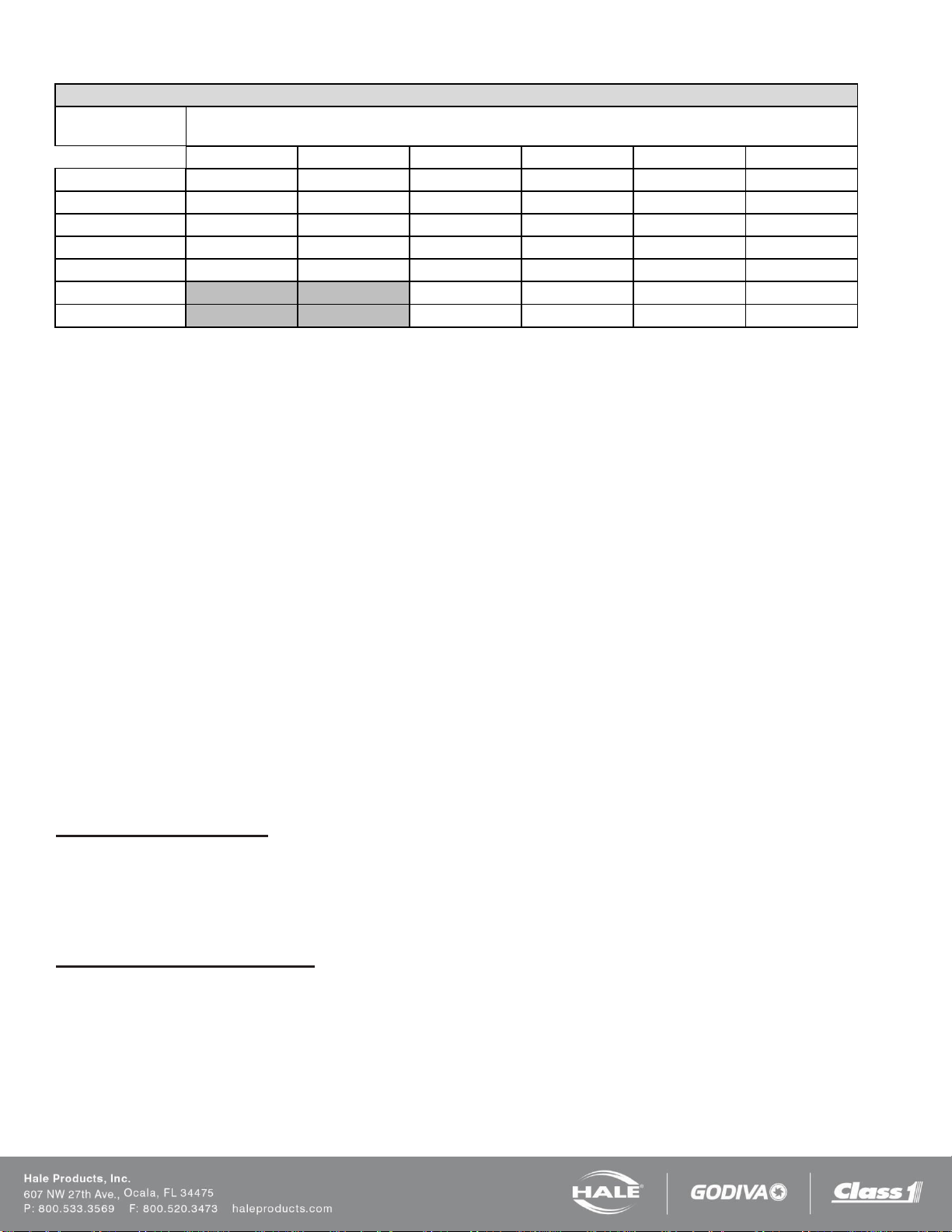
The maximum rated foam concentrate flow, in gallons
per minute, is denoted by the model number. Table 1:
Maximum Foam Solution Flows shows the system
capacity at various foam concentrate injection rates for
the Hale SmartFOAM systems.
Page 11
Page 10
SmartFOAM
Maximum Foam Solution Flow
Injection Rate
Percent (%)
Flow rate in GPM [LPM]
1.7AHP
2.1A
3.3
5.0
6.5
Dual 6.5
0.1
1,700 [6,426]
2,100 [7,949]
3,300 [12,492]
5,000 [18,927]
6,500 [24,606]
13,000 [49,213]
0.2
850 [3,213]
1,050 [3,974]
1,650 [6,245]
2,500 [9,464]
3,250 [12,303]
6,500 [24,606]
0.3
567 [2,143]
700 [2,650]
1,100 [4,164]
1,667 [6,310]
2,167 [8,202]
4,333 [16,404]
0.5
340 [1,285]
420 [1,590]
660 [2,498]
1,000 [3,785]
1,300 [4,921]
2,600 [9,843]
1.0
170 [643]
210 [795]
330 [1,249]
500 [1,893]
650 [2,461]
1,300 [4,921]
3.0
110 [416]
167 [632]
217 [820]
433 [1,640]
6.0
55 [208]
83 [314]
108 [410]
217 [820]
Table 1: Maximum Foam Solution Flows
LOW PRESSURE STRAINER
A low pressure foam concentrate strainer is mounted at the inlet of the foam pump. The strainer protects the pump from
debris that might accumulate in the foam concentrate tank. The strainer/valve assembly has a composite non-metallic
housing with stainless steel mesh strainer element and includes a service shut-off valve.
The valve inlet offers 1/2” NPT (13 mm) threads, with a fitting to connect a 1/2” (13 mm) ID foam concentrate suction
hose.
The strainer and valve are low pressure devices and are designed for installations where the strainer IS NOT subject to
HIGH pressure flushing water.
HIGH PRESSURE STRAINERS (FS Series)
Hale FS series strainers (FS15 and FS25) are panel mounted with a 500 PSIG (34 BAR) pressure rating, suitable for use
where flushing water pressure must pass through the strainer.
The FS15 strainer uses 3/4” (19mm) NPT connection ports and a 1-1/2” NST cap. It is suitable for use with Class “A” and
low viscosity Class “B” foam concentrates.
The FS25 strainer uses 1” (25mm) NPT connection ports and a 2-1/2” NST cap. It is suitable for use with both Class “A”
and Class “B” foam concentrates.
TANK SELECTOR VALVES
SmartFOAM models 3.3, 5.0, and 6.5 may use dual foam tanks for A and B foam concentrates. Selection of the desired
foam concentrate tank with the ADT panel mounted toggle switch or MDT II selector automatically changes the foam
concentrate injection rate to the preset default rate for the selected foam tank. No further operator Intervention is required.
The ADT, MDT II and MST include the check valves and connection points to provide foam pump flushing capabilities.
Air Dual Tank Selector (ADT)
The Air Dual Tank (ADT) valve is an air operated foam tank selector valve that enables selection of foam concentrate
dependent on fire ground operational demands.
The ADT is an integral part of the foam pump and provides an electrical interlock for the low tank level sensors and
concentrate injection rate. A panel mounted selector toggle switch with indicator lights controls foam concentrate tank
selection and shows which foam concentrate tank is in use.
Manual Dual Tank Selector (MDT II)
The Manual Dual Tank (MDT II) selector valve is available for the Hale Foam systems with dual tanks. The MDT II is a
panel mounted, manually operated selector that provides selection of foam concentrate dependent on fire ground
operational demands.
The MDT II also provides an electrical interlock for the low tank level sensors and concentrate injection rate. The MDT II is
not suitable for top mount operator panel installations and some side operator panels due to gravity feed requirements of
foam concentrate to the foam pump.
Page 12
Page 11
SmartFOAM
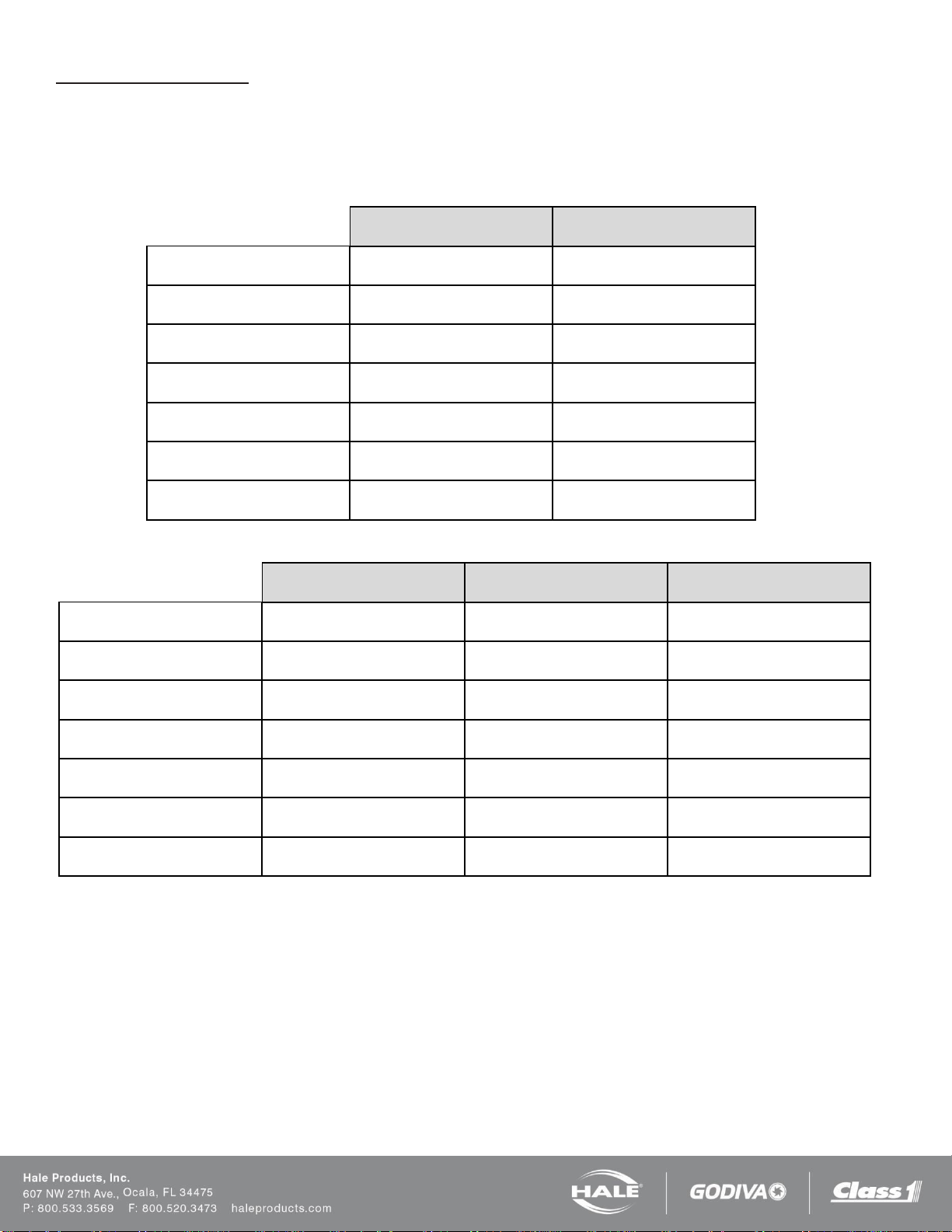
1.7AHP
2.1A
Foam Pump Type
Piston Pump, Dual Plunger
Piston Pump, Dual Plunger
Maximum Foam Concentrate
Output
1.7 GPM (6.5 LPM)
2.1 GPM (8 LPM)
Maximum System Operating
Pressure
400 PSI (27.5 BAR)
250 PSI (17 BAR)
Maximum Operating
Temperature
160°F (71°C)
160°F (71°C)
Pump Motor
0.44 HP (0.3 Kw), 12 VDC
0.44 HP (0.3 Kw), 12 VDC
Operating Ampere Draw
30 AMPS @ 12 VDC
25 AMPS @ 12 VDC
Maximum Ampere Draw
40 AMPS @ 12 VDC
40 AMPS @ 12 VDC
3.3
5.0
6.5
Foam Pump Type
Rotary Gear Positive
Displacement
Rotary Gear Positive
Displacement
Rotary Gear Positive
Displacement
Maximum Foam Concentrate
Output
3.3 GPM (13 LPM)
5.0 GPM (19 LPM)
6.5 GPM (24.6 LPM)
Maximum System Operating
Pressure
400 PSI (27.5 BAR)
250 PSI (17 BAR)
200 PSI (13.8 BAR)
Maximum Operating
Temperature
160°F (71°C)
160°F (71°C)
160°F (71°C)
Pump Motor
0.75 HP (0.6 Kw), 12 VDC
0.75 HP (0.6 Kw), 12 VDC
1.25 HP (0.9 Kw), 12 VDC
Operating Ampere Draw
30 AMPS @ 12 VDC
30 AMPS @ 12 VDC
40 AMPS @ 12 VDC
Maximum Ampere Draw
60 AMPS @ 12 VDC
60 AMPS @ 12 VDC
80 AMPS @ 12 VDC
Manual Single Tank (MST)
Single tank foam systems can be configured with a Manual Single Tank (MST) selector, which provides a flush function
connection to the foam system electronic controls.
HALE FOAM SYSTEM SPECIFICATIONS
Table 2: Specifications – 1.7 and 2.1
Table 3: Specifications – 3.3, 5.0, and 6.5
Page 13
Page 12
SmartFOAM
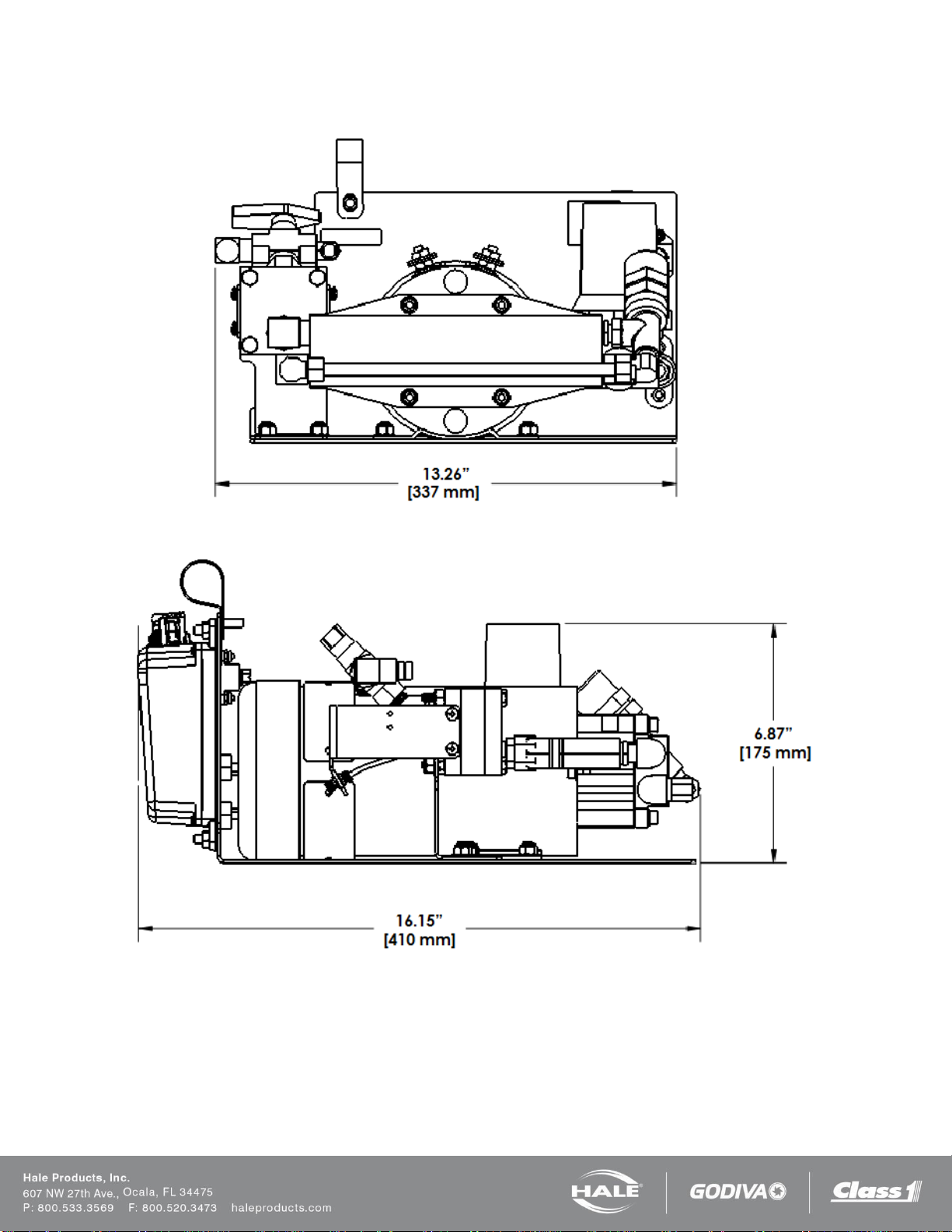
HALE FOAM PUMP DIMENSIONS
Figure 1: 1.7 and 2.1 Foam Pump Installation Envelope Dimensions
Page 14
Page 13
SmartFOAM
Figure 2: 3.3 and 5.0 Foam Pump Installation Envelope Dimensions
Page 15
Page 14
SmartFOAM
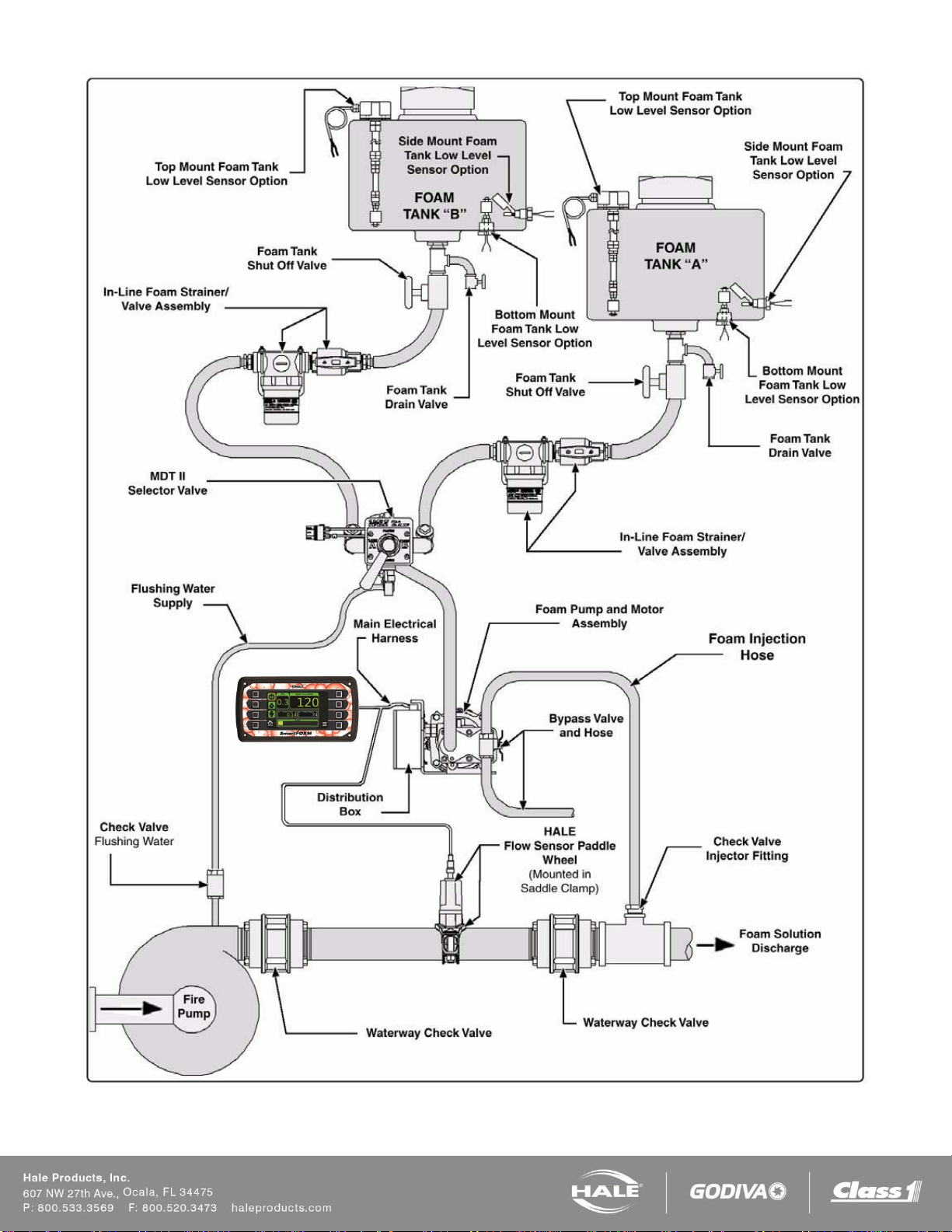
SYSTEM DIAGRAM
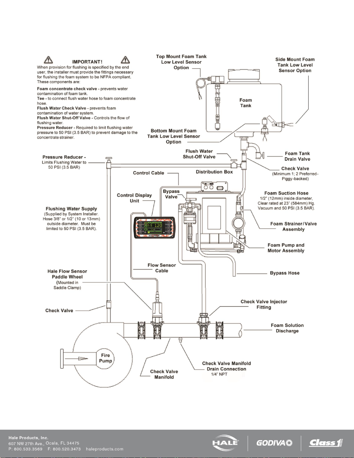
Figure 3: Typical Hale SmartFOAM 2.1A and 1.7AHP System
Page 16
Page 15
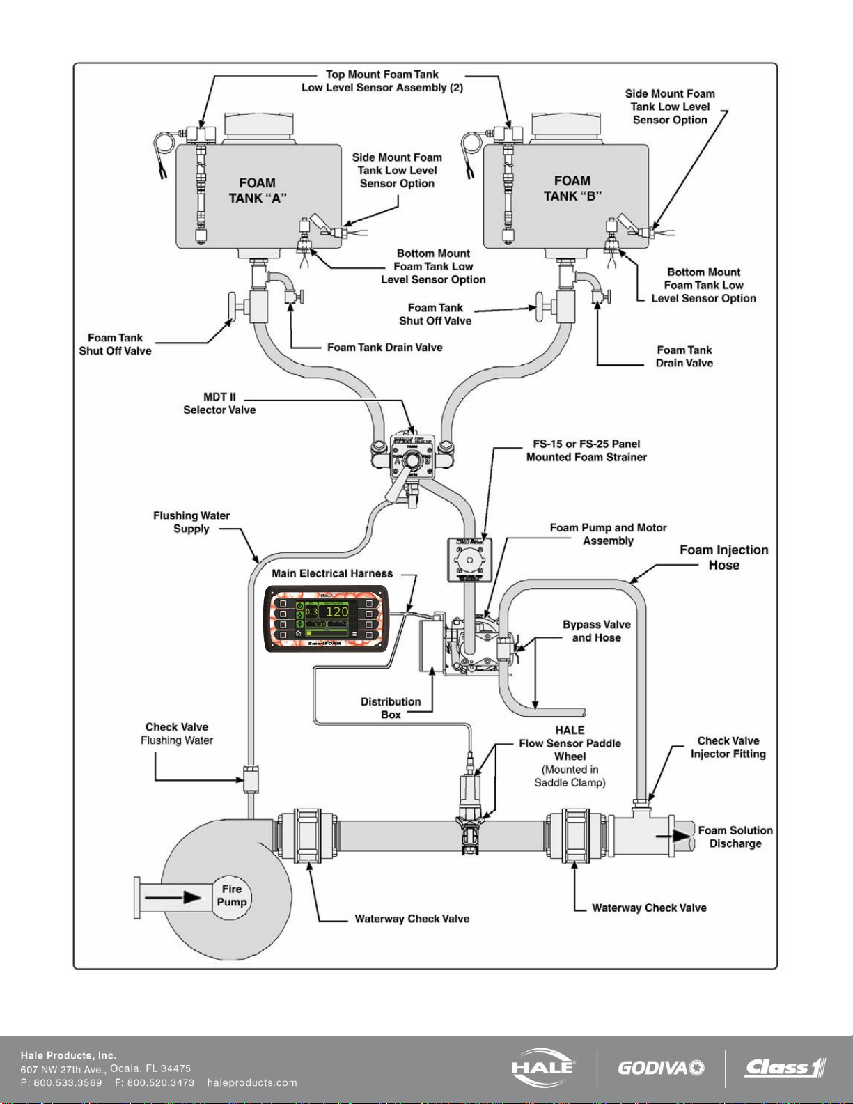
SmartFOAM
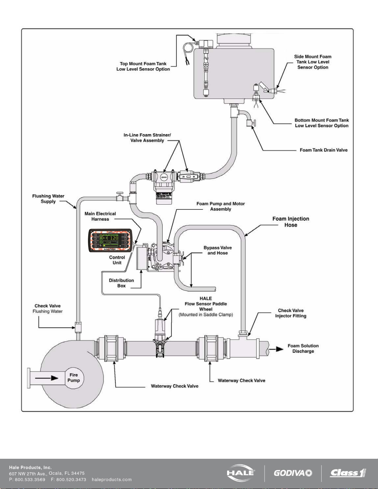
Figure 4: SmartFOAM 3.3, 5.0, 6.5 Single Tank System with In-line Strainer
Page 17
Page 16
SmartFOAM
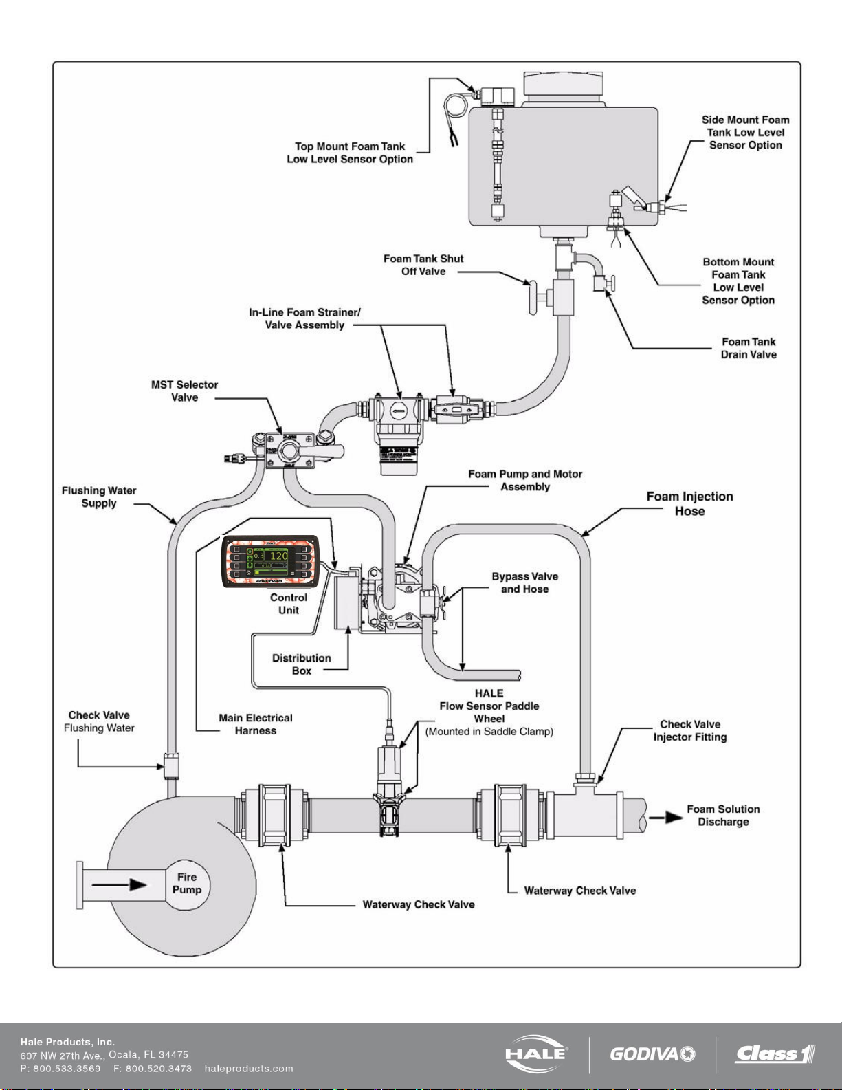
Figure 5: SmartFOAM 3.3, 5.0, 6.5 Single Tank with MST and In-line Strainer
Page 18
Page 17
SmartFOAM
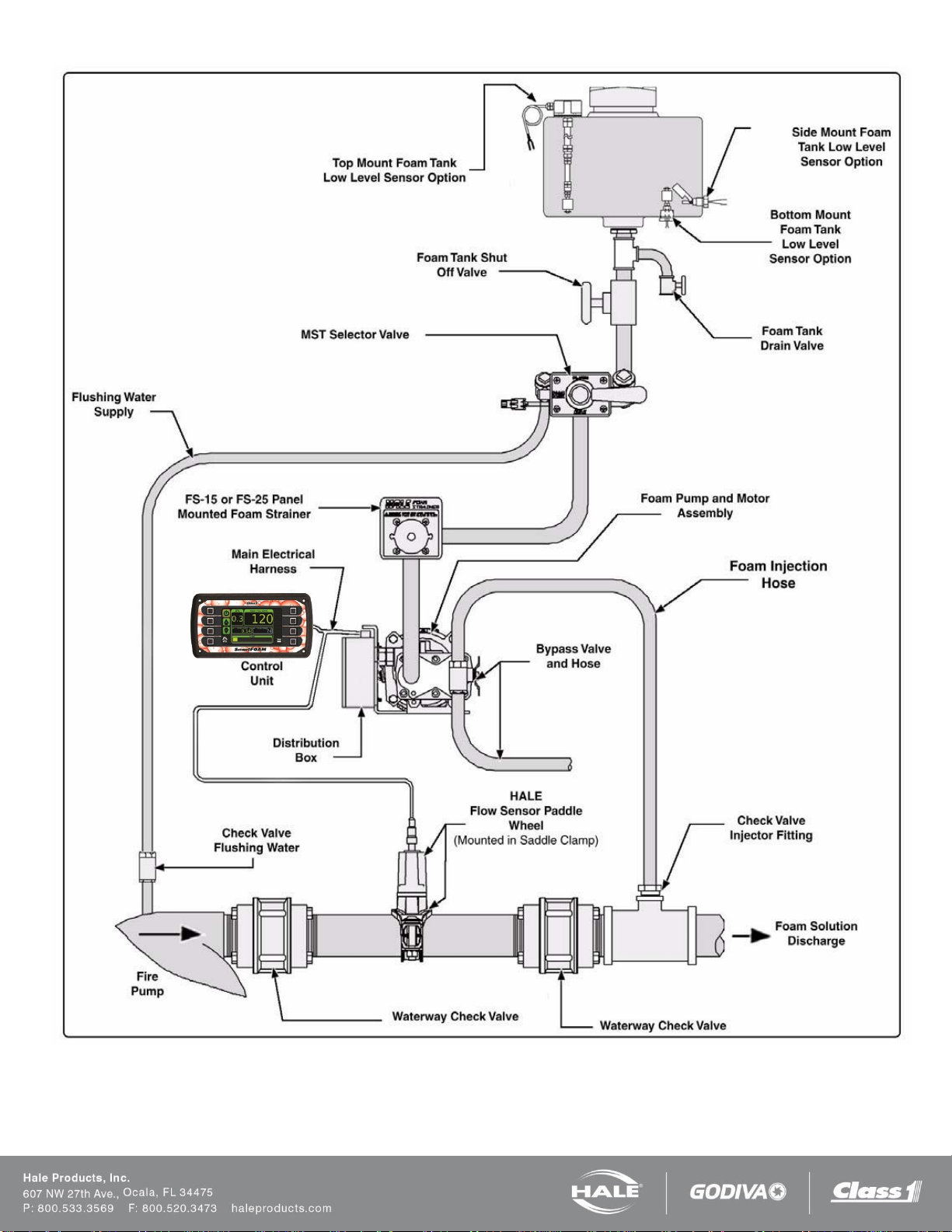
Figure 6: SmartFOAM 3.3, 5.0, 6.5 Single Tank with MST and FS Series Strainer
Page 19
Page 18
SmartFOAM
Figure 7: SmartFOAM 3.3, 5.0, 6.5 Dual Tank with MDTII and In-line Strainer
Page 20
Page 19
SmartFOAM
Figure 8: SmartFOAM 3.3, 5.0, 6.5 Dual Tank with MDTII and FS Series Strainer
Page 21

Page 20
SmartFOAM
Figure 9: SmartFOAM 3.3, 5.0, 6.5 Dual Tank with ADT and In-line Strainer
Page 22
Page 21
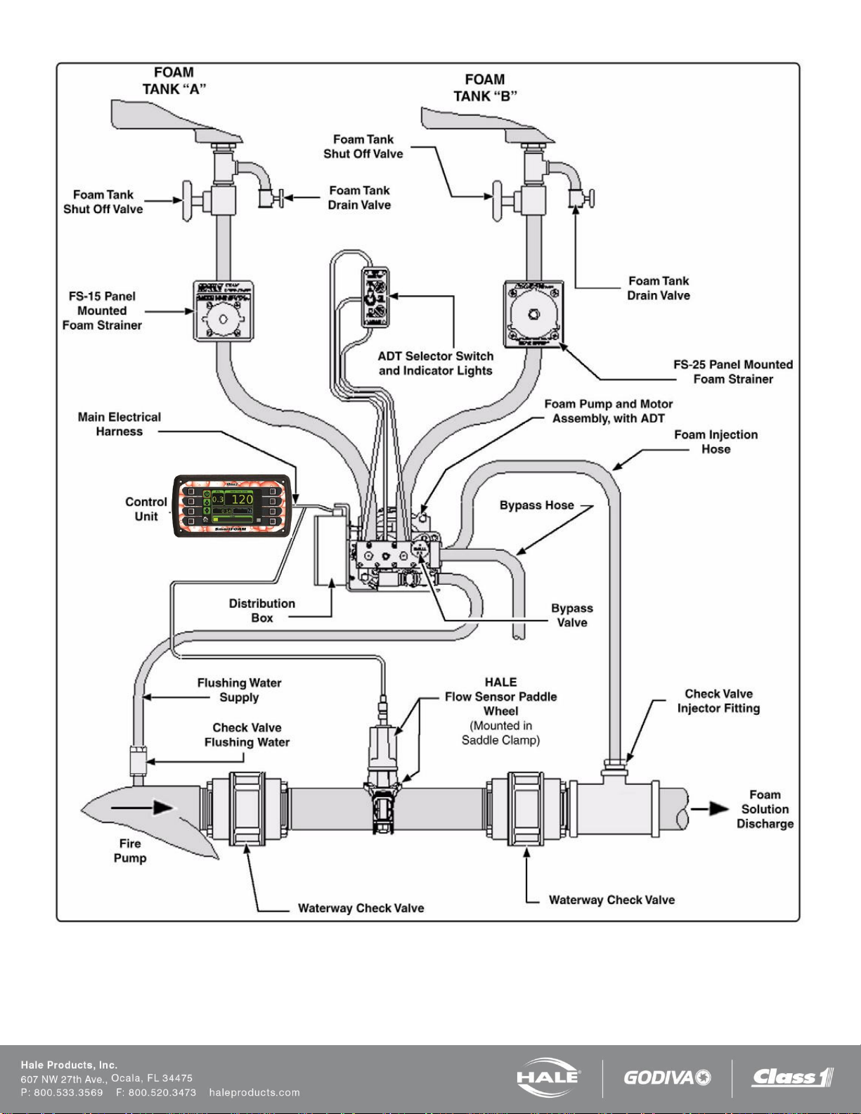
SmartFOAM
Figure 10: SmartFOAM 3.3, 5.0, 6.5 Dual Tank with ADT and FS Series Strainer
Page 23
Page 22
SmartFOAM
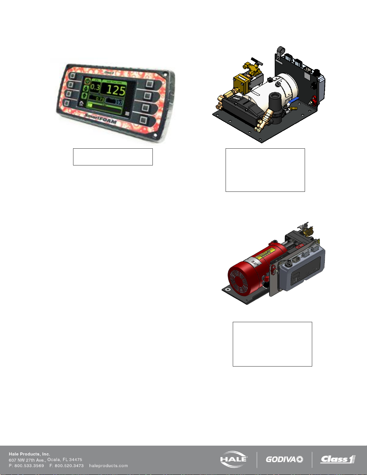
SmartFOAM controller
610-00039
SmartFOAM Base Unit, Foam
Pump/Motor Assembly
2.1A – 12V: 115498
2.1A – 24V: 115499
1.7AHP – 12V: 119276
1.7AHP – 24V: 119277
SmartFOAM Base Unit, Foam
Pump/Motor Assembly
3.3 – 12V: 501-3120-05-0
3.3 – 24V: 501-3120-06-0
5.0 – 12V: 501-3130-05-0
5.0 – 24V: 501-3130-06-0
6.5 – 24V: 501-4480-04-0
CONTROLLER AND BASE PUMP
Page 24
SmartFOAM
Check valve / Injector fitting
038-1790-00-0
SmartFOAM controller
harness
Single pump (10’x14’)
513-00101-200
Single pump (15’x19’)
513-00101-201
Dual pump
513-00074-200
Water Flow sensor input module
610-00033
(NOT REQUIRED WITH 610-00044)
1.7, 2.1 Foam system placard
101-1630-70-0
3.3, 5.0, 6.5 Foam system placard
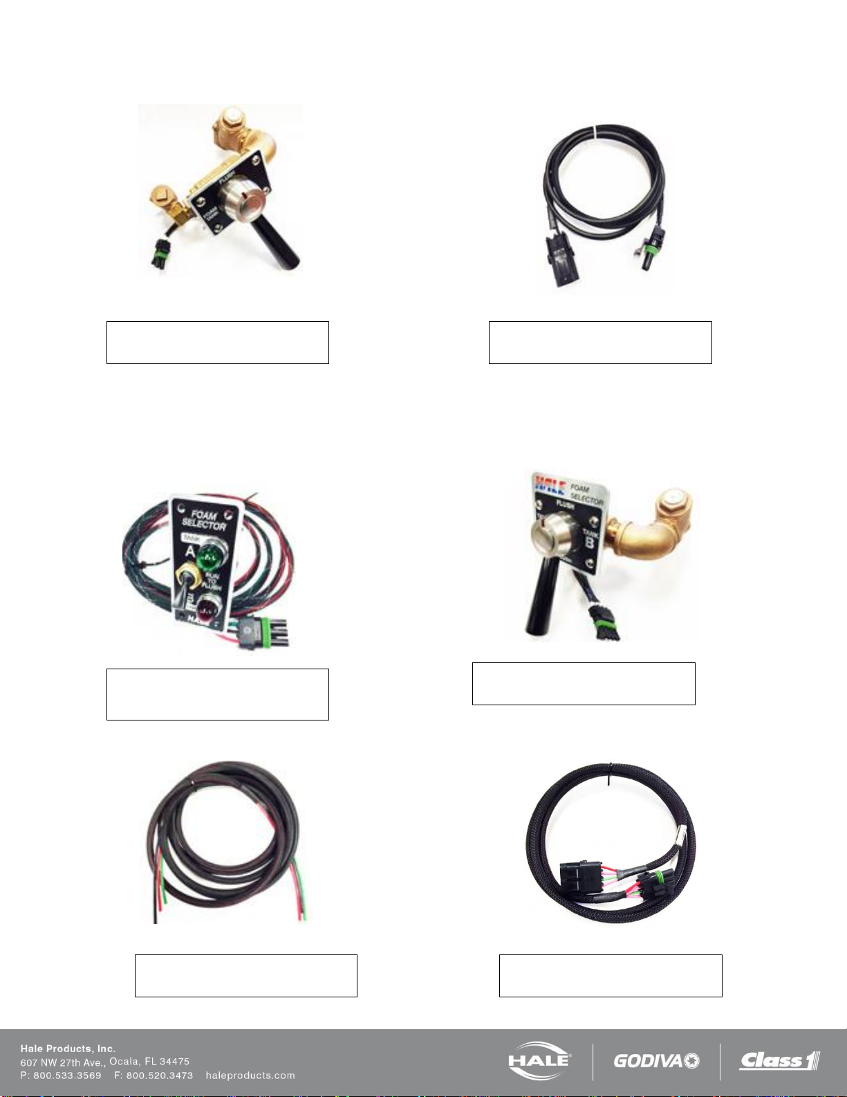
Inline strainer - 101-1630-58-0
MST and FS strainer – 101-1631-12-0
MDTII and FS strainer – 101-1631-07-0
Page 23
Page 25
Page 24
SmartFOAM
MDTII (Manual Dual Tank)
538-1490-14-0
ADT (Air Dual Tank)
12V – 538-1640-05-0
24V – 538-1640-06-0
MDTII harness extension (6 feet)
513-0320-02-0
ADT color-coded air tubing extension
507-0380-00-0
MST harness extension (6 feet)
513-0320-07-0
MST (Manual Single Tank)
538-1490-12-0
SINGLE CONCENTRATE TANK OPTIONS
DUAL CONCENTRATE TANK OPTIONS
Page 26
SmartFOAM
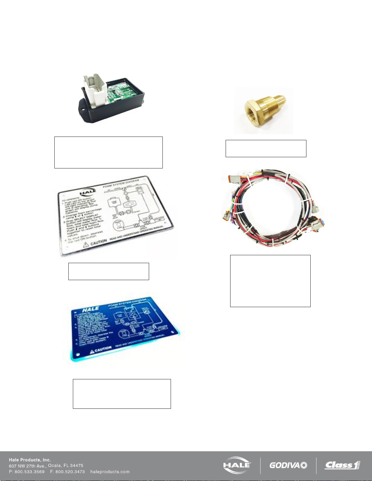
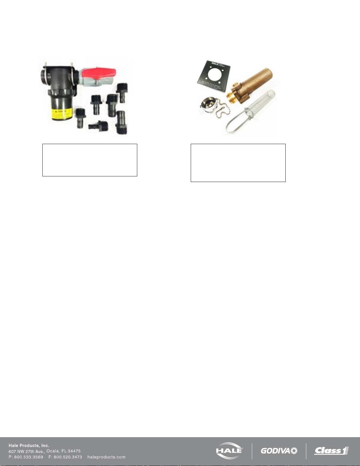
In-line strainer/valve assembly
510-0190-01-0
(Do not use if subject to flushing water
pressure)
FS panel mount strainers
FS-15 – 510-0150-00-0
¾” NPT threads
FS-25 – 510-0180-00-0
1” NPT threads
STRAINER OPTIONS
Page 25
Page 27
Page 26
SmartFOAM
Pipe Size vs. Flow Range
Pipe size
Flow Range
GPM
LPM
1.5”
10 – 350
38 – 1,219
2.0”
20 – 550
76 – 2,082
2.5”
30 – 800
114 – 3,028
3.0”
50 – 1,250
189 – 4,731
4.0”
75 – 1,800
284 – 6,813
3” Single Check
Valve (SCV)
30 - 750
114 – 2,839
3” Dual Check Valve
(DCV)
30 - 750
114 – 2,839
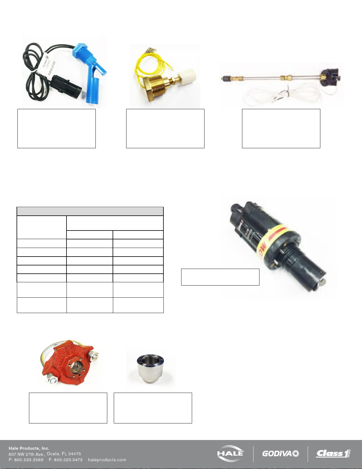
Side mount (1/2 inch NPT)
200-2110-02-0
½ inch NPT threaded bushing to
mount from outside foam tank.
Bottom mount (1 inch NPT)
200-2100-04-0
1 inch NPT threaded bushing to
mount from outside foam tank
Top mount
200-2110-06-0
Extends from 2.5 feet to 5 feet –
may be cut shorter if required.
Flow sensor weld fitting
Stainless steel – 082-3060-00-0
Steel – 309020
Aluminum - 309010
Flow sensor saddle clamp
2.0 inch – 4842010
2.5 inch – 4843010
3.0 inch – 4844010
Flow sensor paddlewheel
102714
LOW TANK SENSOR OPTIONS
FLOW SENSOR OPTIONS
Each Hale foam system requires a flow sensor for operation. Pipe size must be selected based on the minimum and
maximum water flow in the foam capable discharge. Following is a list of pipe size and rated flow ranges, along with flow
sensor saddle clamp part number. In all instances, a weld fitting may be substituted for the saddle clamp.
Table 4: Pipe Size versus Flow Range
Page 28
Page 27
SmartFOAM
Single Check Valve (SCV)
3.0” 538-1850-00-0
Dual Check Valve (DCV)
3.0” 538-1840-00-0
Wafer Check Valve
3.0” 038-1570-06-0
4.0” 038-1570-08-0
Type 115 Flange
3.0” NPT 115-0080-00-0
2.5” NPT 115-0070-00-0
2.0” NPT 115-0060-00-0
BLANK 115-0050-00-0
Type 2433D Flange
4.0” NPT 115-0040-00-0
3.0” NPT 115-0030-00-0
2.5” NPT 115-0020-00-0
BLANK 115-0010-00-0
115 Flange Gasket
046-0050-00-0
2433D Flange Gasket
046-0040-00-0
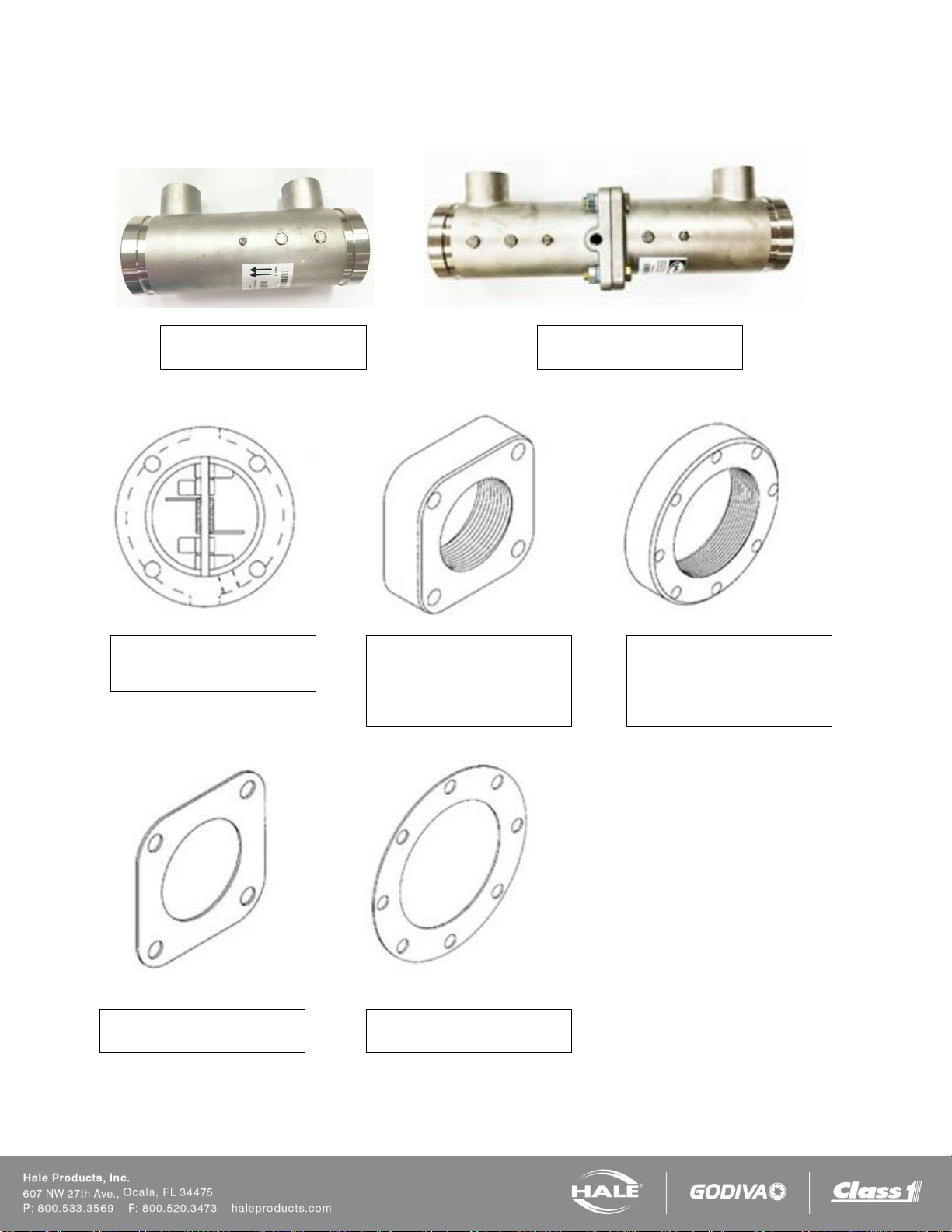
CHECK VALVE MANIFOLDS, FLANGES AND GASKETS
The check valve manifolds include flow sensor, check valve/injector fitting and a single or dual waterway check valve
flappers. End connections for the manifolds are 3 inch Victaulic.
Page 29

Page 28
SmartFOAM
Close Fit Flanged Elbow
098-0140-00-0
115 flange inlet with 3” Victaulic
output
Close Fit Flanged Elbow
098-0190-00-0
2433D flange inlet with 3” NPT
female and 4” Victaulic output
Close Fit Flanged Elbow
098-0050-00-0
115 flange inlet with 2.5” NPT
female output
Close Fit Flanged Elbow
098-0020-00-0
115 flange inlet with 115 flange
output
Mini-Manifold
178-0320-02-0
ELBOWS AND MANIFOLDS
Page 30

Page 29
SmartFOAM
Switch with indicator
513-0330-01-0
Harness
513-0680-00-0
REMOTE START OPTION
Page 31

Page 30
SmartFOAM
IMPORTANT!
CAUTION!
INSTALLATION
The following guidelines are offered to assist the system
installer with a complete system installation.
Carefully review the procedures that follow to ensure the
system is properly designed. This section lists
components that have been tested with Hale SmartFOAM
and provide the best system performance. Use of the
recommended materials and specified parts ensures a
virtually maintenance free installation.
Differences in apparatus plumbing and foam system
configuration make it impractical to show exactly how the
Hale SmartFOAM systems are installed on a particular
apparatus.
The information contained in this section, however, applies
to most situations and should be used when designing
and installing Hale SmartFOAM systems. A system
plumbing and electrical diagram is provided at the end of
this section to assist with installation.
Before proceeding with system installation, carefully
review the procedures that follow to ensure the system is
properly designed.
The Hale SmartFOAM system is supplied with five major
components that must be located on the apparatus:
❑ Foam pump motor and assembly
❑ Control unit
❑ Instructions/system diagram placard
❑ Flow sensor
❑ Check valve injector fitting
Notes: The flow sensor and check valve injector fitting
may be pre-mounted, if a manifold or pre-configured
package is ordered.
Optional components that require mounting on the
apparatus include:
❑ Mini manifold
❑ Flanged elbows
❑ Manual Single Tank (MST) selector valve
❑ Manual Dual Tank (MDTII) selector valve
❑ Air Dual Tank (ADT) operating switches and
indicator lights
❑ Foam tank(s)
❑ FS Series panel mounted foam strainers
❑ Remote activation switch and indicator
WHEN DETERMINING THE LOCATIONS OF HALE
SMARTFOAM COMPONENTS BEING INSTALLED KEEP
IN MIND PIPING RUNS, CABLE ROUTING AND OTHER
INTERFERENCES THAT COULD HINDER OR
INTERFERE WITH PROPER SYSTEM PERFORMANCE.
FOAM PUMP AND MOTOR ASSEMBLY
The foam pump and motor assembly must be located in an
area that is protected from road debris and excessive heat
build-up. The back of a compartment or a compartment
shelf is often an ideal location. The foam system, bypass
valve, strainer and shut-off valve are located on the foam
pump and motor assembly and access to these components
must be provided.
The foam pump and motor assembly must be mounted
below the discharge of the foam tank to provide for gravity
feed to the foam pump. The foam tank must be located
where refilling can be easily accomplished with 5 gallon (19
liters) pails and other methods suitable to the end user. Most
water tank manufacturers build the foam tank into the
booster tank.
When specifying a foam tank, make sure provisions are
made for:
❑ Installation of the low tank level sensor
❑ Foam suction connections
❑ Tank drainage
❑ Proper fill openings, per NFPA requirements
In addition, a foam tank refill system may be required. See
Hale EZFill system for installation requirements.
FOAM CONCENTRATE STRAINER
Determine a location on the apparatus to mount the foam
strainer.
THE IN-LINE STRAINER/VALVE ASSEMBLY IS A LOW
PRESSURE DEVICE THAT WILL NOT WITHSTAND
FLUSHING WATER PRESSURE. WHEN INSTALLING
THE IN-LINE STRAINER IN SYSTEMS EQUIPPED WITH
HALE “MDT II” OR HALE “MST,” MAKE SURE THE INLINE STRAINER/VALVE ASSEMBLY IS IN THE HOSE ON
THE INLET SIDE OF THE VALVE.
IF THE STRAINER IS SUBJECT TO FLUSHING WATER
PRESSURE, USE HALE “FS” SERIES STRAINERS.
Mount the in-line foam strainer/valve assembly in the foam
concentrate hose from the foam tank to the foam pump
suction connection, ADT, MDT II or MST.
Page 32

SmartFOAM
IMPORTANT!
If panel mounted FS series strainers are installed, mount
the strainer in the foam concentrate hose that supplies
concentrate to the ADT, MDT II or MST. The FS series
strainer may also be mounted in the outlet hose of the
MDT II or MST.
WHEN DETERMINING THE STRAINER LOCATION
KEEP IN MIND THE REQUIREMENT FOR GRAVITY
FEED OF FOAM CONCENTRATE TO THE FOAM PUMP
THROUGH THE STRAINER AND AVOID AIR TRAPS IN
THE HOSES. ALSO, CLEARANCE MUST BE
PROVIDED TO ALLOW REMOVAL OF THE BOWL
ASSEMBLY TO CLEAN THE STAINLESS STEEL
MESH, TO MAKE HOSE CONNECTIONS TO THE
STRAINER AND FOR OPERATION OF THE SERVICE
VALVE.
The installer must provide a strainer service isolation valve
in the foam concentrate hose to prevent spillage during
service. An MST or MDT II can serve this purpose.
CONTROL UNIT AND INSTRUCTION /
SYSTEM DIAGRAM PLACARD
Determine a location on the operator panel of the
apparatus for the control unit and instruction/ system
diagram placard, if provided. These components must be
located at the main pump operator position in close
proximity to each other. Consideration must be given for
routing the control cable from the control unit to the motor
controller on the foam pump and motor assembly. If
necessary, order longer or shorter cable assemblies to suit
the location demands.
INSTALLER SUPPLIED COMPONENTS
Due to the many differences in apparatus configurations
and design requirements the Hale SmartFOAM system
installer must supply components such as:
❑ Mounting brackets
❑ Piping
❑ Hoses
❑ Fittings
❑ Electrical wiring
❑ Foam tank(s)
The following guidelines are recommendations for
selection of additional components for a complete system
installation. These recommendations reflect materials and
components that are tested extensively with Hale
SmartFOAM systems and provide proven reliable
performance.
Page 31
FOAM CONCENTRATE SUCTION HOSE
SmartFOAM 2.1A and 1.7 AHP Foam systems
These systems are provided with 15’ (4.6 meters) of 1/2”
(13mm) ID reinforced PVC foam concentrate suction hose.
The system installer may need to supply additional fittings
and hose from the foam tank to the inlet of the foam pump.
All components selected transfer foam concentrate;
therefore they must be compatible with the foam
concentrates being used in the system.
SmartFOAM 3.3, 5.0, and 6.5 Foam systems
Hoses for Class “A” foam concentrates have minimum 3/4”
(19mm) inside diameter. Hoses for Class “B” foam
concentrates must have a minimum 1” (25.4mm) inside
diameter due to higher viscosity of the concentrate.
Note: Certain types of Class “B” AFFF-ARC or ATC
concentrates require a 1-1/4” or 1-1/2” (32mm or 38mm) ID
foam concentrate supply line.
Hoses for the foam concentrate suction that are not subject
to high pressure, i.e. flushing water or foam concentrate
discharge, must have a rating of 23” (584.2mm) Hg vacuum
and 50 PSI (3.5 BAR) pressure or greater.
Note: NFPA requires that foam concentrate suction hose be
clear to observe foam concentrate flow during foam pump
operation.
Recommended components
Hose: PVC, Kuriyama Kuri-Tec K3130 or K7130 series.
Fittings: Hose Barb Type; Brass, Stainless Steel or Nylon.
Foam concentrate suction hose subjected to flushing water
pressure must be rated for 23 in (584.2mm) Hg vacuum and
the maximum discharge pressure of the fire pump (500 PSI
[34 BAR] minimum). These hoses include the hose from the
outlet of the MDT II or MST to the foam pump inlet.
Recommended components
Hose: Aeroquip 2580 series or Equivalent Reinforced
Hydraulic Hose.
Fittings: Brass or Stainless Steel Hose End Crimp or
Reusable Type (Aeroquip 412 series or
Equivalent).
A foam tank shut-off valve and drain valve should be
provided in the foam tank suction hose to allow strainer
service, tank drainage and easier priming.
These components are subject to the same material
characteristics and pressure ratings as stated above. When
the In-line strainer/valve assembly option is installed the
shut-off valve is included. A separate valve is not required.
Page 33

Page 32
SmartFOAM
FOAM CONCENTRATE DISCHARGE HOSE
The system installer must supply fittings and hoses from
the foam pump inject connection to the check
valve/injector fitting inlet. All components selected transfer
foam concentrate, therefore they must be compatible with
the foam concentrates being used in the system.
The foam pump discharge connection is a 1/2” (13 mm)
compression fitting. The check valve injector fitting
connection has 1/2” NPT threads. Hoses and fittings of
1/2” minimum diameter rated at 500 PSI (34.5 BAR)
working pressure or maximum discharge pressure of the
fire pump must be used. Fittings and hoses must be
compatible with all foam agents to be used.
Recommended components
Hose: Aeroquip 2580-8 or Equivalent Reinforced
Hydraulic Hose.
Fittings: Brass or Stainless Steel Hose End Crimp or
Reusable Type (Aeroquip 412-9-8 or
Equivalent).
Note: Although air brake tubing has been used for foam
concentrate discharge hose, it is not as flexible as the
hydraulic hose and readily kinks during installation.
Additionally, the air brake tubing may not meet NFPA 500
PSI (34 BAR) test requirements.
FOAM CONCENTRATE BYPASS HOSE
The foam concentrate bypass hose connection is a 1/2”
(13mm) hose barb connection. Hoses and fittings of
nominal 1/2” diameter must be used as bypass hose.
Since the bypass hose is used for calibration and draining
the system it does not see high operating pressures;
therefore, a hose with a lower pressure rating than the
inject hose may be used.
Fittings and hoses used must be compatible with all foam
agents expected to be used. Use fittings made of brass or
300 series stainless steel compatible with all foam
concentrates.
Recommended components
Hose: Low Pressure Hydraulic Hose or Air Brake
Tubing.
Fittings: Brass or Stainless Steel.
It is recommended that the foam concentrate bypass hose
be long enough to extend past the apparatus running
board to reach five (5) gallon (19 liter) containers, making
foam pump setup and calibration simpler.
CHECK VALVES
Check valves must be installed on the apparatus with foam
systems to prevent contamination of the foam concentrate
with water and contamination of the fresh water tank with
foam. When a Hale SmartFOAM foam Injection system and
related components are properly installed the required check
valves are integral parts of the system.
NFPA standards require a check valve in the foam
concentrate injection line at the injection point. The Hale part
number 038-1790-00-0 Integral Check Valve/ Injector Fitting,
a standard component included with the Hale SmartFOAM
system and installed when a manifold kit is ordered, meets
these requirements and threads directly into the foam
injection port on Hale manifolds.
Check valves must be installed in all water piping locations
where foam concentrate could drain back into pumps or
other components of the fire apparatus.
As a minimum one check valve must be installed where the
water piping that supplies foam solution connects to the fire
pump discharge. To more effectively keep foam
contamination out of the fire pump and water tank, double
check valves are recommended.
Separate two check valves by at least 6” to 8” (152 to
203mm) of piping to form a dead zone between the check
valves. Individual drain lines should be used on each check
valve. The waterway check valves must be rated for 500
PSIG (34.5 BAR) test pressure.
FLUSHING WATER HOSE
Flushing water connections for the Hale ADT, MDT II or
MST require using 1/2” (13mm) inside diameter tubing and
appropriate fittings. The tubing and fittings used must be
capable of withstanding the maximum fire pump discharge
pressure (500 PSI [34 BAR] minimum) and must be
compatible with foam concentrates being used in the
system.
When the ADT, MDT II or MST is installed, a check valve is
used integral to the flushing water line connection. This
provides protection against water system contamination with
foam concentrate.
Note: The installer/builder should provide an additional
check valve and shut-off valve where the flushing water
hose connects to the water pump.
Hale recommends the use of one of the above selector
options to provide foam system flushing capabilities.
However, if the Hale SmartFOAM system is ordered with the
“no tank” option the system installer must maintain NFPA
compliance.
Page 34

SmartFOAM
IMPORTANT!
Models 1.7 and 2.1
Maximum length
8 AWG (8.4mm2)
6 ft (1.8M) or less
4 AWG (21.2mm2)
6 ft (1.8M) to 15 ft (4.6M)
0 AWG (53.5mm2)
15 ft (4.8M) or Longer
Models 3.3, 5.0, 6.5
Maximum length
4 AWG (21.2mm2)
6 ft (1.8M) or less
0 AWG (53.5mm2)
6 ft (1.8M) to 15 ft (4.6M)
00 AWG (67.5mm2)
15 ft (4.8M) or Longer
To be NFPA compliant, when flushing is required, the
system installer must provide proper:
❑ Hoses
❑ Shut-off valves
❑ Check valves
❑ Reducer/regulator
❑ Connections for flushing water for the system
FOAM DISCHARGE DRAINS
Drains must be provided from foam capable discharge
piping components to prevent freezing in cold weather.
When designing the drain system care must be taken to
prevent contamination of the water system with foam and
the foam concentrate with water. Some multiple drain
systems that allow individual drain lines to communicate
also allow foam to bypass the installed check valves
causing contamination of fire pump and the water or foam
concentrate storage tanks.
Hale offers an optional manual or air-operated 6-port drain
valve, Class1 Model MMD6 (p/n: 104961). The valve
provides individual drains with a single control and is use
for applications where a single point for multiple drains is
required. If a Hale MMD6 drain valve is not used,
individual drain lines and valves for foam capable
discharge piping is recommended.
APPARATUS DESIGN/BUILD FOR COLD
WEATHER (BELOW FREEZING) DUTY
If the end-user will use the fire apparatus in sub- freezing
temperatures, the onus is on the fire truck builder to build
into the apparatus design an appropriate ambient
temperature operating environment for the envelope
where the SmartFOAM system will be located. This
routinely takes on the form and function of mounting the
SmartFOAM system in a limited ventilation area that is
served by an appropriate pump house auxiliary heater.
Simply, the fire truck builder must keep ambient air
temperature above 32°F (0°C) in the envelope around the
SmartFOAM hardware, including the base foam pump
unit, foam strainer, foam concentrate injection line, etc.
There are several best practices in the fire industry that
can be employed to meet this criteria and the fire truck
builder/designer can choose the best choice for their
specific installation. Note that there must be ventilation
available to cool the area around the unit also, to prevent
electric motor overheating when the unit is operating in
high temperature ambient environments.
ELECTRICAL REQUIREMENTS
The system installer must provide the primary power wire
and a ground strap for the Hale SmartFOAM system.
Primary power must be supplied from the main apparatus
battery to the motor controller box on the foam pump and
motor assembly. The Hale SmartFOAM 2.1A and 1.7AHP
Page 33
systems require a minimum of a 40 AMP electrical service.
The Hale SmartFOAM 3.3 and 5.0 systems require a
minimum of a 60 AMP electrical service. The Hale
SmartFOAM 6.5 system requires a minimum of a 80 AMP
electrical service
Primary electrical power must be supplied directly from the
battery, the battery master disconnect switch, or solenoids to
the Hale SmartFOAM system.
OTHER ELECTRICAL COMPONENTS MUST NOT BE
SUPPLIED FROM THIS WIRE. DO NOT CONNECT THE
PRIMER AND HALE SMARTFOAM TO THE SAME
POWER WIRE.
The primary power connection must be made so that power
is supplied to the Hale SmartFOAM when the main
apparatus electrical system is energized and the pump is in
gear. Use of a solenoid with a 150 AMP peak, 85 AMP
continuous rating is recommended. Figure 11:
Recommended Relay Wiring Schematic shows the
recommended wiring for this relay.
Note: This ensures immediate operation when the operator
places the apparatus in PUMP mode, and to prevent battery
power drain when the apparatus is not running.
Make certain that the recommended wire gage is selected
for the primary power connection based on the run length
(see Table 5: Recommended Primary Power Cable
Sizes). Use solder lugs on cable ends with a 5/16” (8mm)
diameter hole.
Table 5: Recommended Primary Power Cable Sizes
Page 35

Page 34
SmartFOAM
IMPORTANT!
Figure 11: Recommended Relay Wiring Schematic
When planning cable runs make sure the primary wires
are routed by the shortest most direct route.
A braided flat ground strap connected to the apparatus
chassis is recommended for the ground connection.
This limits the RFI/EMI interference encountered with
radios, computers or other sensitive electronic equipment.
The ground strap should be a minimum of 1-1/4” (32mm)
wide and no longer than 18” (457mm). It must have
soldered flat lug ends with 3/8” (10mm) diameter holes. If
the ground strap length exceeds 18” (457mm), a wider
ground strap should be used or use a double thickness of
1-1/4” (32mm) wide ground strap. The ground strap must
be connected to the chassis. Use minimum 5/16” (8 mm)
diameter bolt or mounting to secure the strap.
Power and ground must also be provided for the display
unit using the 2 pin Packard connector. The power must
be a minimum 5 amp dedicated and fused circuit. The
ground must be connected to the chassis ground stud and
protected from corrosion. Make sure the ground is
attached directly to the chassis frame and not to the
apparatus body work.
FOAM CONCENTRATE TANK
A foam concentrate tank must be supplied to suit the
capacity required for the apparatus application. The tank
must meet NFPA minimum standards for its design capacity,
including:
❑ Filler size
❑ Vapor pressure venting
❑ Baffling
❑ Drain facilities
FOAM PUMP MOUNTING
Position the foam pump and motor assembly in the desired
location on the apparatus. When installing the foam pump
and motor assembly, the assembly should be kept in a
HORIZONTAL position with the base plate on the bottom
(See Figure 12: SmartFOAM Piston Pump Installation).
BEFORE MAKING GROUND CONNECTIONS REMOVE
ALL PAINT, GREASE AND COATINGS FROM THE
CONNECTION AREA. AFTER MAKING CONNECTION,
SEAL AGAINST CORROSION. WHEN A FLAT GROUND
STRAP IS NOT AVAILABLE USE A BATTERY CABLE
ONE SIZE LARGER THAN THE POWER CABLE USED.
Figure 12: SmartFOAM Piston Pump Installation
Page 36

SmartFOAM
Figure 13: SmartFOAM Gear Pump Installation
Although the system is sealed and designed to be
resistant to the harsh environment of fire-fighting
apparatus, a compartment with easy operator access is
recommended.
The base plate of the foam pump and motor assembly
must be anchored to a surface or structure that is rigid and
of adequate strength to withstand the vibration and
stresses of apparatus operation.
The base of the foam pump and motor assembly includes
5/16” (8mm) diameter predrilled mounting holes. The
apparatus mounting location must to be drilled
accordingly. The base plate may be used as a template to
mark mounting hole locations.
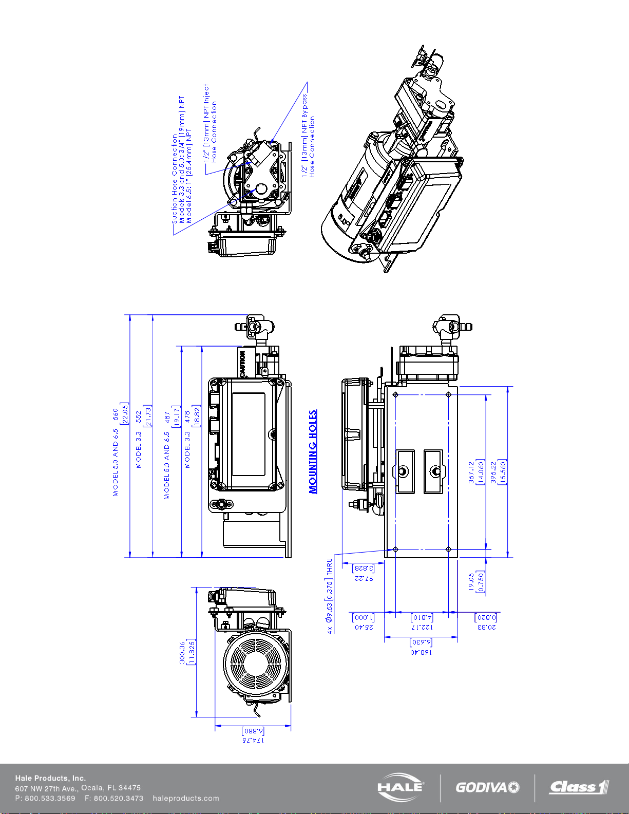
Page 35
Figure 14: Base Plate Mounting Hole Locations – 1.7 and
2.1 provides the mounting base dimensions for the
SmartFOAM 1.7AHP and 2.1A foam pump and motor
assembly.
Figure 15: Base Plate Mounting Hole Locations – 3.3, 5.0,
and 6.5 provides the mounting base dimensions for the
SmartFOAM 3.3, 5.0, and 6.5 foam pump and motor
assembly.
Make sure the foam concentrate hoses are properly routed
to the inlet and outlet on the foam pump.
Foam concentrate must gravity feed to the foam pump inlet
from the foam tank(s). The foam pump must be mounted in
an area to avoid excessive engine exhaust system heat or
accessory heat build-up.
Page 37

Page 36
SmartFOAM
Figure 14: Base Plate Mounting Hole Locations – 1.7 and 2.1
Figure 15: Base Plate Mounting Hole Locations – 3.3, 5.0, and 6.5
Page 38

Page 37
SmartFOAM
IMPORTANT!
PLUMBING INSTALLATION
Hale SmartFOAM System plumbing diagram is located below. The diagram provides recommended guidelines for the
installation of system components that handle water, foam concentrate and foam solution. The sequence in which the
plumbing installation is completed depends on your individual installation requirements.
AFTER INSTALLATION, MAKE SURE ALL PIPES, HOSES AND TUBES ARE PROPERLY SUPPORTED USING THE
BEST INDUSTRY PRACTICES. USE A SUITABLE PIPE SEALING COMPOUND AT ALL JOINTS.
WATER AND FOAM SOLUTION PLUMBING
Use best industry practices when installing the water and foam solution piping runs. Use a suitable pipe sealing compound
at all joints.
CHECK VALVE MANIFOLD
Hale pre-made stainless steel foam manifolds are recommended. The manifolds are available in kits and eliminate the extra
labor and leaks from large pipe thread connections. The manifolds use 3” (76mm) Victaulic connections and are available in
single or dual check valve configurations. Figure 16: Check Valve Manifold Installation shows a typical check valve
manifold installation.
Figure 16: Check Valve Manifold Installation
Note: When the manifold is installed the drain tap that must be placed in the “down” position and plumbed to an individual
drain.
Page 39

Page 38
SmartFOAM
When properly mounted, the flow sensor and check
valve/injector fitting are on the side of the manifold and one
of the drain ports is on the bottom. The flow sensor should
point upwards slightly to allow drainage of water and
sediment. See Figure 19: Flow Sensor Tee Position
Range.
OPTIONAL HALE PIPING COMPONENTS
Hale piping components, such as 3” (76mm) and 4”
(102mm) wafer-type check valves, 115 and 2433 series
flanges, mini manifold, etc. are available to simplify
installation of water and foam solution discharge piping.
The arrangement shown in Figure 17: Typical Midship
Pump Installation provides accurate proportioning across
a wide range for up to four discharges from the mini
manifold.
The Hale mini manifold provides a 1” NPT tap for
installation of the check valve/injector fitting.
The Hale mini manifold and elbow components offer 4-3/8”
diameter bolt circles and minimize fabrication and pipe
work. After installation, make sure all pipes, hoses and
tubes are supported using the best industry practices.
Figure 18: Typical 4 Inch Check Valve Installation
(Midship Pump) shows a suggested installation
arrangement using Hale 4” (102mm) check valves, pipe
and Hale 2433 flanges.
Figure 17: Typical Midship Pump Installation
Page 40

Page 39
SmartFOAM
Figure 18: Typical 4 Inch Check Valve Installation (Midship Pump)
Page 41

Page 40
SmartFOAM
Pipe Size
Minimum Recommended
Straight Run Pipe
1-1/2 in (38.1 mm)
9 in (228.6 mm)
2 in (50.8 mm)
12 in (304.8 mm)
2-1/2 in (63.5 mm)
15 in (381 mm)
3 in (76.2 mm)
18 in (457.2 mm)
4 in (101.6 mm)
24 in (609.6 mm)
WATERWAY CHECK VALVES
Check valves in the waterway, rated at 500 PSI (34.5
BAR), are required to keep foam solution out of the main
pump and allow pump priming without drawing foam into
the piping.
Using double check valves, separated by at least 6” to 8”
(152 to 203mm) of pipe before the foam injection point,
ensures that the pump and tank water remain
uncontaminated.
FLOW SENSOR
The Hale SmartFOAM flow sensor is specially designed
to enable quick and easy sensor inspection and
maintenance. The flow sensor paddle wheel is installed
on a saddle clamp or weld fitting to the foam-capable
discharge piping of the apparatus.
In horizontal piping runs, the flow sensor is mounted
within the range shown in Figure 19: Flow Sensor Tee
Position Range.
Figure 19: Flow Sensor Tee Position Range
When selecting a flow sensor, it is important to consider
the minimum and maximum flow requirements during
operation. Refer to the Table 4: Pipe Size versus Flow
Range, for the proper pipe size for flow range desired.
The flow sensor is installed in the piping before the foam
concentrate injection point.
This is true in applications where the foam system needs
to supply a 3” (76mm) deck gun, as well as a 1”
(25.4mm) booster line.
Table 6: Pipe Size versus Minimum Straight Run
Pipe size for flow sensor mounting must be selected to
provide accuracy at the lowest flow rate. Mounting the
flow sensor in a short section of pipe, one pipe size
smaller (e.g., 4” to 3”; 3” to 2-1/2”, etc.), provides better
accuracy at the lower flows.
Refer to the Table 13: “Pipe Size vs. Minimum Straight
Run” for pipe size. Selecting the next smaller pipe
permits reducing the straight pipe run the required
distance prior to the flow sensor paddle wheel.
In the short length of reduced pipe pressure loss is
minimal and there is minimal pressure loss through
elbows and fittings. See Figure 20: Typical Reduced
Size Sensor Piping Arrangement.
Excessive turbulence in the flow sensor may produce
unstable and inaccurate flow readings. The length of
straight pipe prior to the flow sensor must be sufficient to
reduce any turbulence in the pipe.
The following guidelines help attain the best readings,
and maintain Hale SmartFOAM system accuracy.
1. A minimum of 6 times the pipe diameter of
straight run pipe without any fittings is necessary
prior to the flow sensor paddle wheel. (See
Figure 21: Flow Sensor Placement).
2. The downstream piping length is not as critical,
but there must be a short length of straight pipe
with no fittings or valves immediately after the
flow sensor paddlewheel. Two to three times the
pipe diameter is recommended.
3. Do not mount a flow sensor directly after an
elbow or valve. Valves create severe turbulence
when they are “Gated”.
Page 42

Page 41
SmartFOAM
Figure 20: Typical Reduced Size Sensor Piping Arrangement
Figure 21: Flow Sensor Placement
SADDLE CLAMP INSALLATION
See Figure 22: Flow Sensor/Saddle Clamp
Installation.
Installation of the paddlewheel flow sensor using a
saddle clamp requires a 1.385/1.390 inch (35/35.3 mm)
bored hole in the pipe.
A minimum of six times the pipe diameter of straight run
pipe without any fittings is necessary prior to the position
of this hole.
Figure 22: Flow Sensor/Saddle Clamp Installation
The flow sensor requires a spacer and eight stainless
steel internal hex head screws. These are supplied with
the sensor.
Four 6-32 x1/2 inch screws attach the spacer to the
saddle clamp mount and four 6-32 x 3/4 inch screws with
lock washers attach the paddlewheel to the spacer.
Page 43

Page 42
SmartFOAM
CAUTION!
CAUTION!
CAUTION!
Align the indexing pin of the saddle clamp to the
indexing hole of the spacer to align the saddle clamp
mount.
Secure with four 1/2” machine screws, no lock washers.
Torque to 8.5 in.-lbs. (1.0 N-m).
Align the paddle wheel indexing pin to the indexing hole
in the spacer and secure using four 3/4” screws and lock
washers. Torque to 7.5 in.-lbs. (0.9 N-m).
Apply a small amount of grease to the saddle clamp
gasket before the final installation of the assembly onto
the pipe. Firmly tighten the saddle clamp onto the pipe.
FOAM PUMP FLUSH SYSTEM
Dual Tank System
Flushing water must be provided to flush the system of
foam concentrate after each use. This prevents adverse
reactions of some foam concentrates should they mix
together. The Hale ADT and MDT II each have
provisions for connecting flushing water to the foam
concentrate injection system.
Single Tank System
The Hale MST provides a selector valve and gives the
system flush capabilities for NFPA compliance. A fitting
provided on the Hale MST simplifies the flushing water
connection.
No Tank Option
The system installer must provide a flushing water
supply to comply with NFPA standards.
The flushing water hose must be a minimum of 1/2” (12
mm) inside diameter and capable of withstanding the
maximum fire pump discharge pressure, 500 PSI (34
BAR) minimum. The flush water supply should be
provided from one of the pressure taps on the discharge
of the fire pump.
It is recommended that a check valve be installed at the
pressure tap to prevent contamination. Flush water
thread connections are:
❑ ADT - 1/2” (13mm) NPT
❑ MDT II and MST - 1/4” (6.4mm) NPT
The system installer must provide proper fittings for
these connections.
FOAM CONCENRATE PLUMBING
MAKE SURE THE FOAM TANK AND FOAM
CONCENRATE SUCTION HOSES ARE CLEAN
BEFORE MAKING A FINAL CONNECTION TO FOAM
PUMP. FLUSH TANK(S) AND HOSES PRIOR TO
MAKING CONNECTIONS. MAKE SURE THE FOAM
CONCENRATE IS GRAVITY FED FROM THE TANK
TO THE PUMP.
Foam concentrate plumbing consists of:
❑ Foam concentrate suction hose
❑ Foam strainer
❑ Foam concentrate discharge hose
❑ Check valve/injector fitting
FOAM STRAINER CONNECTION
THE FOAM CONCENTRATE STRAINER ASSEMBLY,
MOUNTED ON THE FOAM PUMP INLET, IS A LOW
PRESSURE DEVICE. IT WILL NOT WITHSTAND
FLUSHING WATER PRESSURE. IF FLUSHING
WATER IS TO BE PROVIDED THE PRESSURE MUST
BE LIMITED TO 50 PSI (3.5 BAR).
The strainer/valve assembly has 1/2” (12mm) NPT
female threaded ports. A 1/2” hose barb fitting is
supplied to connect the 1/2” ID hose, provided with the
Hale SmartFOAM 2.1A installation kit.
The hose from the foam tank to the strainer must have
adequate wall stiffness to withstand the vacuum of the
foam pump while it is operating (23” [584 mm] Hg and
50 PSI [3 BAR], Kuriyama, Kuri-tec K-3130 or K-7130
series or equal).
After the foam pump is mounted on the apparatus,
connect the PVC hose provided to the strainer inlet.
Install the clear plastic hose from the foam tank outlet to
the inlet of the strainer/valve assembly. The inlet is on
the valve end. Wetting the ends of the hose and fittings
makes the installation on the hose fittings easier.
MAKE SURE THE FOAM TANK AND FOAM
CONCENTRATE SUCTION HOSES ARE CLEAN
BEFORE MAKING FINAL CONNECTION TO FOAM
PUMP. IF NECESSARY FLUSH TANK AND HOSES
PRIOR TO MAKING CONNECTION.
Page 44

Page 43
SmartFOAM
CAUTION!
IN-LINE STRAINER VALVE
THE IN-LINE STRAINER/VALVE ASSEMBLY, MOUNTED ON THE FOAM PUMP INLET, IS A LOW PRESSURE
DEVICE. IT CANNOT WITHSTAND FLUSHING WATER PRESSURE. WHEN INSTALLING THE IN-LINE STRAINER
EQUIPPED WITH HALE MDT II OR MST, MAKE SURE THE IN-LINE STRAINER/VALVE ASSEMBLY IS IN THE HOSE
ON THE INLET SIDE OF THE VALVE. IF THE STRAINER IS SUBJECT TO FLUSHING WATER PRESSURE, USE
HALE FS SERIES STRAINERS.
The strainer/valve assembly has 1-1/4” (32mm) NPT female threaded ports. Fittings are supplied for connection to the
following inside diameter hose, depending on the viscosity of foam concentrates used. (See Figure 3-14: “In-Line
Strainer/Valve Installation,” on page 67.)
❑ 3/4” (19mm)
❑ 1.00” (25mm)
❑ 1-1/4” (32mm)
Use 3/4” (19mm) inside diameter hose for Class “A” foam and a 1.00” (25mm) inside diameter hose for Class “B” foams.
For high viscosity Class “B” foam concentrates use 1-1/4” (32mm) or 1-1/2” (38mm) inside diameter hose. (See Figure 23:
In-Line Strainer/Valve Installation). A bracket is included to permit installation on the apparatus.
To Install the In-Line Strainer/Valve Assembly
1. Choose a location on the apparatus that allows gravity feed from the foam tank to the strainer inlet and from the
Notes: When selecting the strainer location, make sure there is sufficient space above and below the strainer.
❑ A minimum of 5” (127 mm) below for removal of the strainer basket and screen for cleaning
❑ 2” (51 mm) above to permit operation of the service valve
2. Mark 4 holes to mount the foam strainer bracket. Drill tapped holes for 1/4”-20 UNC screws (#7 drill for
Figure 23: In-Line Strainer/Valve Installation
strainer outlet to the foam pump suction connection.
¼-20 UNC tap)...or...drill clearance holes for 9/32” (7 mm) for 1/4”-20 UNC screws. (See Figure 24: In-
Line Strainer Mounting Bracket).
Page 45

Page 44
SmartFOAM
CAUTION!
FS SERIES STRAINER
When a pressurized water flush is provided to the
strainer from one of the discharges, Hale FS series
strainers are required. The plumbing exposed to the
flush water pressure must be rated at or above the
operating pressure of all other discharge plumbing
components (500 PSI/34 BAR minimum).
To Install FS Series Strainers
1. Choose a location on the apparatus that allows
gravity feed from the foam tank to the strainer
inlet and from the strainer outlet to the foam
pump suction connection.
Figure 24: In-Line Strainer Mounting Bracket
3. Secure the bracket and strainer/valve assembly
to the apparatus.
4. Select the appropriate fittings from the bag
attached to the strainer assembly. Two of each
fitting are included with the strainer assembly.
For fitting selection vs. type of foam concentrate
(see Figure 23: In-Line Strainer/Valve
Installation).
5. Coat all fitting threads with Permatex #80724 (or
equal) plastic pipe thread sealant. Install the
fittings into the strainer/valve assembly ends and
tighten.
6. Install the clear plastic hose from the foam tank
outlet to the inlet of the strainer/valve assembly.
(Figure 23: In-Line Strainer/Valve Installation).
Wet the ends of the hose and fittings to make
the installation easier.
2. When selecting the strainer location make sure
there is sufficient space behind the pump panel
to attach hoses and fittings. Also make sure the
inlet connection port is oriented correctly. (See
Figure 25: FS Strainer Orientation).
Figure 25: FS Strainer Orientation
3. Remove the strainer cap, mounting screws and
nameplate from the strainer assembly.
4. Mark holes for mounting the foam strainer by
using the nameplate as a guide, or see Figure
26: FS Strainer Mounting Dimensions.
MAKE SURE THE FOAM TANK AND FOAM
CONCENTRATE SUCTION HOSES ARE CLEAN
BEFORE MAKING FINAL CONNECTION TO FOAM
PUMP. IF NECESSARY, FLUSH THE TANK AND
HOSES PRIOR TO MAKING THE CONNECTION.
7. Install the clear plastic hose from the in-line
strainer/valve assembly outlet to the inlet of the
Hale MDT II, Hale MST, foam concentrate
pump, or the correct fitting on Hale ADT.
5. Select the appropriate fittings to attach the
hoses to the strainer. Two of each fitting are
included with the strainer assembly. The fittings
and hoses must be capable of withstanding the
vacuum generated by the foam pump (23 inches
[584 mm] Hg) and the maximum flushing water
pressure (500 PSI [34 BAR]).
6. For FS-15 strainers use 3/4” (19mm) NPT x 3/4”
hose fittings. For FS-25 strainers use 1” (25mm)
NPT x 1” hose fittings.
7. Coat all fitting threads with a suitable thread
sealant. DO NO USE Teflon Tape. Install the
fittings into the strainer/valve assembly ends and
tighten.
Page 46

Page 45
SmartFOAM
CAUTION!
Figure 26: FS Strainer Mounting Dimensions
8. Make sure the strainer is properly oriented (see Figure 25: FS Strainer Orientation). Apply Loctite #242
Threadlock Compound (or equal) to the screws then secure the strainer body and nameplate to the apparatus.
Install the strainer cap.
9. Install the clear plastic hose from the foam tank outlet to the inlet of the strainer. Wet the ends of the hose and
fittings to make the installation easier.
MAKE SURE THE FOAM TANK AND FOAM CONCENTRATE SUCTION HOSES ARE CLEAN BEFORE MAKING
FINAL CONNECTION TO FOAM PUMP. IF NECESSARY, FLUSH TANK AND HOSES PRIOR TO MAKING
CONNECTION.
10. Install the clear plastic hose from the strainer outlet to the inlet of the Hale SmartFOAM foam pump, or the
selector valve.
Page 47

Page 46
SmartFOAM
CHECK VALVE / INJECTOR FITTING
The Hale check valve/injector fitting, supplied with the
Hale SmartFOAM system, meets NFPA requirements for
a non-return device in the foam injection system. It
prevents back flow of water into the foam concentrate
tank.
When properly installed the brass and stainless steel
construction check valve/injector fitting ensures foam
concentrate is injected into the center of the water flow
for better mixing.
Note: Always position the check valve/ injector fitting at
a horizontal or higher angle to allow water to drain away
from the fitting. (See Figure 27: Check Valve Injector
Fitting Installation). This avoids sediment deposits or
the formation of an ice plug.
The check valve/injector fitting MUST be mounted in a
location that is common to all discharges which require
foam concentrate. (See Figure 28: Injection and
Bypass Hose Connections).
The Hale SmartFOAM system DOES NOT permit a
separate injection point for each foam capable
discharge.
The check valve/injector fitting has – 1” NPT (25.4mm)
threads on the outside, to fit into the 1” NPT threaded
connection on the Hale mini manifold a pipe tee, or a 1”
NPT weld fitting installed in the discharge piping of the
fire pump. (See Figure 27: Check Valve Injector Fitting
Installation).
The inlet connection of the check valve/ injector fitting
uses a 1/2” NPT female thread.
Figure 27: Check Valve Injector Fitting Installation
Page 48

Page 47
SmartFOAM
Figure 28: Injection and Bypass Hose Connections (1.7 and 2.1)
Figure 29: Injection and Bypass Hose Connections (3.3, 5.0, and 6.5)
FOAM CONCENTRATE INJECTION HOSE
Connect a hose from the foam pump inject port to the inlet of the check valve injector fitting. (See Figure 28: Injection
and Bypass Hose Connections or Figure 29: Injection and Bypass Hose Connections (3.3, 5.0, and 6.5)).
The hose and fittings from the INJECT port to the check valve injector fitting should have minimum 1/2” (13 mm) outside
diameter and be rated at 500 PSI (34 BAR) working pressure (Aeroquip 2580-10 or equal).
Page 49

Page 48
SmartFOAM
This hose is used for calibrating the foam pump, pumping the
concentrate into a container to empty the foam tank or to assist in
priming of the foam pump. The hose from the BYPASS port must
be long enough to reach a container outside the truck.
Note: If the handle or placard is removed from the bypass valve
for repairs or to facilitate remote mounting make sure they are
installed on the valve correctly. Make sure the tang on the handle
engages the cast stops. (See Figure 30: Bypass Valve
Assembly).
Figure 30: Bypass Valve Assembly
BYPASS HOSE CONNECTION
Models 1.7AHP and 2.1A
A bypass valve is mounted on the discharge of the foam pump. The bypass handle must be accessible by the pump
operator during normal operations.
The bypass is a 3-way directional valve. Determine which port is the INJECT port and which port is the BYPASS. (See
Figure 28: Injection and Bypass Hose Connections).
Bypass hose connections are 1/2”. Hose fittings compatible with all foam concentrates must be provided. The hose from
the BYPASS port is plumbed to the atmosphere.
This hose is used for calibrating the foam pump, pumping the concentrate into a container to empty the foam tank or to
assist in priming of the foam pump. The hose from the BYPASS port must be long enough to reach a container outside
the truck.
Models 3.3, 5.0, and 6.5
A bypass port is provided on the discharge side of the ADT, or a 1/4 turn bypass valve is mounted on the discharge of the
foam pump when the ADT option is not installed. (See Figure 30: Bypass Valve Assembly).
The bypass handle must be accessible by the pump operator during normal operations. (See Figure 29: Injection and
Bypass Hose Connections (3.3, 5.0, and 6.5)).
The bypass is a 3-way directional valve. Determine which port is the INJECT port and which port is the BYPASS. (See
Figure 30: Bypass Valve Assembly). Bypass hose connections are 1/2” (13mm). Hose fittings compatible with all foam
concentrates must be provided. The hose from the BYPASS port is plumbed to the atmosphere and should not receive
HIGH pressure.
Page 50

Page 49
SmartFOAM
Figure 31: ADT Option Panel Placard Layout
Dimensions
Figure 32: ADT Air Hose Connection, Part 1
ADT OPTION AIR CONNECTIONS
If the ADT option is used, install the operating switch and indicator light placard on the apparatus operator panel. A
mounting cutout diagram is provided (see Figure 31: ADT Option Panel Placard Layout Dimensions).
After mounting the placard assembly install the air hoses from the ADT to the placard assembly. Make sure proper
connections are made at the placard assembly (see Figure 32: ADT Air Hose Connection, Part 1).
A color coded decal attached to the ADT valve assembly along with an optional color coded air hose harness simplifies air
hose connections. If the optional air hose harness is not used, 1/4” (6mm) inside diameter air brake tubing can be
substituted. Make sure the air brake tubing selected has the proper DOT approval (see Figure 32: ADT Air Hose
Connection, Part 1 and Figure 33: ADT Option Air Hose Connections, Part 2).
When cutting the air harness or air brake tubing to size make sure the ends are square using a tubing cutter or razor
knife.
Page 51

Page 50
SmartFOAM
Figure 33: ADT Option Air Hose Connections, Part 2
Page 52

SmartFOAM
CAUTION!
ELECTRICAL CONNECTIONS
Complete harness electrical diagrams are provided - see
Figure 35: SmartFOAM Harness Connections. Refer
to these diagrams for proper installation of each of the
electrical components.
The Hale SmartFOAM system is designed to be installed
with a minimum of electrical connections. Cables are
provided with each Hale SmartFOAM system to make
the flow sensor, control unit and motor controller
connections.
The system installer must supply primary power wire,
low tank level sensor wire and flat braided ground
straps.
Review the “Safety” section of this manual in
its entirety before proceeding with electrical
connections.
❑ To prevent system damage or electrical shock the
main power supply wire must be the last connection
made to the Hale SmartFOAM motor controller.
❑ The cables provided with each Hale SmartFOAM
system contain shielded assemblies.
❑ NEVER attempt to shorten or lengthen the shielded
cables. If necessary order
❑ longer or shorter cables from Hale Products to suit
the particular installation.
❑ The cables are indexed so they connect to the
correct receptacle one way only. When making cable
connections DO NOT force mismatched connections
as damage can result, causing improper system
operation.
Page 51
❑ The cables shipped with each Hale SmartFOAM are
tested at the factory with that unit. Improper handling
and forcing connections can damage these cables
which could result in other system damage.
❑ The system can only perform when the electrical
connections are sound. Make sure each electrical
connection is correct.
❑ Hale SmartFOAM systems are designed for use on
direct current, negative (–) ground apparatus
electrical systems only.
❑ Do not mount radio transmitter or transmitter cables
in direct or close contact with the Hale SmartFOAM
unit.
❑ Before connecting the cables, inspect the O-ring
seal in the female connector. If the seal washer is
missing or damaged, water can enter the connector
causing corrosion of the pins and terminals resulting
in possible system failure.
❑ The ground strap must be a minimum of 1-1/4”
(32mm) wide and no longer than 18” (457mm).
❑ A longer ground strap must be wider or a double
thickness strap must be used. Make sure the ground
strap is attached to the chassis frame. Grounding to
the body IS NOT acceptable.
❑ Always disconnect the power cable, ground straps,
electrical wires and cables from the control unit or
other Hale SmartFOAM equipment before electric
arc welding at any point on the apparatus. Failure to
do so could result in a power surge through the unit
that could cause irreparable damage.
❑ There are no user serviceable parts inside Hale
SmartFOAM system electrical/ electronic
components. Opening of these components
(distribution box or controller unit) voids the
warranty.
Page 53

Page 52
SmartFOAM
Figure 34: SmartFOAM Controller Unit Mounting Dimensions
CONTROLLER UNIT
The controller unit mounts in the operator panel of the
apparatus. The display is secured with four #6 pan head
screws and nuts (see Figure 34: SmartFOAM
Controller Unit Mounting Dimensions).
The controller requires a 2.0” (52mm) minimum
clearance from the back of the operator panel to allow
proper connection of cables.
Single tank models refer to Figure 35: SmartFOAM
Harness Connections – Single Tank
❑ Connect C1 of the controller harness to the “B”
connector on the rear of the controller unit.
❑ Connect C6 of the controller harness to the “C”
connector on the rear of the controller unit.
❑ Connect C13 on the controller harness to C14 of
the pump harness.
❑ Connect C7 of the controller harness to the water
flow sensor input module.
❑ Connect C3 of the controller harness to the water
flow sensor (paddlewheel).
❑ Connect C10 of the pump harness to the low
foam sensor.
❑ C2 and C4 of the controller harness are used for
options (remote start stop and CAN
communication respectively).
❑ C6, C7, C8, C15, and C16 of the pump harness
are pre-connected by Hale Products at the
factory.
Dual tank models refer to Figure 36: SmartFOAM
Harness Connections – Dual Tank
❑ Connect C1 of the controller harness to the “B”
connector on the rear of the controller unit.
❑ Connect C6 of the controller harness to the “C”
connector on the rear of the controller unit.
❑ Connect C13 on the controller harness to C14 of
the pump harness.
❑ Connect C7 of the controller harness to the water
flow sensor input module.
❑ Connect C3 of the controller harness to the water
flow sensor (paddlewheel).
❑ Connect C8 of the pump harness to the tank A
selector.
❑ Connect C9 of the pump harness to the tank B
selector.
❑ Connect C10 of the pump harness to the tank A
low foam sensor.
❑ Connect C11 of the pump harness to the tank B
low foam sensor.
❑ C2 and C4 of the controller harness are used for
options (remote start stop and CAN
communication respectively).
❑ C6, C7, C15, and C16 of the pump harness are
pre-connected by Hale Products at the factory.
Notes:
Allow a service loop on the controller unit’s harness
connections to prevent “pulling” of the wires or
connectors during body and frame flex.
Page 54

SmartFOAM
CONTROLLER UNIT POWER AND GROUND
CONNECTIONS
Power must be connected directly to the controller unit.
The power connection is the 2-pin Packard connector
(C5) of the controller harness (see Figure 35:
SmartFOAM Harness Connections – Single Tank or
Figure 36: SmartFOAM Harness Connections – Dual
Tank). The mating harness provided is approximately
18” (457mm) long. If additional wire length is required,
use minimum 16 AWG type SXL, or GXL (SAE J1128)
wire.
Page 53
Connect the black (B) wire to a chassis ground stud.
Protect the ground connection from corrosion.
Connect the red (A) wire to the power supply. It is
recommended to connect the power wire to a minimum
5 AMP, fused, dedicated circuit. If a dedicated circuit is
not available, the power lead may be connected to a
terminal where there is not a HIGH current load.
Acceptable additional components powered from this
terminal include ENFO IV, Governor, Tank Level Gauge,
etc.
Figure 35: SmartFOAM Harness Connections – Single Tank
Page 55

Page 54
SmartFOAM
Figure 36: SmartFOAM Harness Connections – Dual Tank
Figure 37: SmartFOAM Power and Ground Connections (1.7, 2.1)
Page 56

Page 55
SmartFOAM
CAUTION!
CAUTION!
MOTOR GROUND / PRIMARY POWER
CONNECT THE PRIMARY POSITIVE LEAD FROM
THE TERMINAL BLOCK TO THE MASTER SWITCH
TERMINAL OR RELAY TERMINAL USING MINIMUM 8
AWG TYPE SGX (SAE J1127), CHEMICAL
RESISTANT, BATTERY CABLE AND PROTECT WITH
WIRE LOOM.
PREVENT CORROSION OF POWER AND GROUND
CONNECTIONS BY SEALING THESE CONNECTIONS
WITH THE SILICONE SEALANT PROVIDED.
GROUND CONNECTION
Be sure the Hale SmartFOAM system is grounded to the
chassis. Use a short length of wide flat ground strap at
least 1-1/4” (32 mm) wide and less than 18” (457 mm)
long to reduce the potential of RFI emitted by this
connection.
A stud is located on the mounting base to attach the
chassis ground strap to the Hale SmartFOAM system.
(See Figure 37: SmartFOAM Power and Ground
Connections (1.7, 2.1)).
When making the ground strap connections make sure
lugs are soldered to the strap ends for trouble free
connections. Seal all connection against corrosion.
When the length of the ground strap exceeds 18” (457
mm) use a wider strap or a double thick strap.
Use 8 AWG minimum type SGX (SAE J1127) battery
cable directly to the battery, battery switch or solenoids
for cable runs up to 6’ (1.8 meters) long. Longer wire
runs may require larger battery cable for proper
operation. DO NOT connect power to the same
connection as the pump primer.
RFI / EMI
Proper installation of system components and cables
along with proper grounding will limit radio interference
caused by the Hale SmartFOAM system. Additionally,
make sure radio cables and hardware are not located in
the immediate area where Hale SmartFOAM equipment
is mounted.
Making round coils of extra control and flow sensor
cables in the pump compartment can act as an antenna.
While the control and flow sensor cables cannot be
shortened, various lengths of cable are available to
minimize the “extra” cable in the truck.
When routing control and flow sensor cables take care to
avoid routing them next to antenna wires, radio power
lines and radio components. When there is extra cable,
double the cable back on itself and secure with plastic
wire ties in a flat bundle instead of making a round coil.
(See Figure 38: Extra Cable Storage).
DO NOT CONNECT THE MAIN POWER LEAD TO
SMALL LEADS THAT ARE SUPPLYING SOME OTHER
DEVICE, SUCH AS A LIGHT BAR OR SIREN. THE
HALE SMARTFOAM MODELS 2.1A AND 1.7AHP
REQUIRE 40 AMP MINIMUM CURRENT.
PRIMARY POWER SUPPLY CONNECTION
Make sure adequate switched electrical power from the
battery positive (+) terminal to the “IN” connection stud
on the motor controller is provided. (See Table 6:
“Recommended Primary Power Cable Sizes”.)
Figure 38: Extra Cable Storage
Page 57

Page 56
SmartFOAM
CAUTION!
FOAM TANK LOW LEVEL SENSOR INSTALLATION
The foam low tank level sensor(s) must be installed and wired to monitor the foam concentrate level (see Figure 39: Low
Level Sensor Mounting Options).
Figure 39: Low Level Sensor Mounting Options
FOAM TANK LOW LEVEL SENSORS MUST BE USED TO PROTECT THE HALE SMARTFOAM FROM DRY
RUNNING. FAILURE TO USE LOW LEVEL SENSORS WITH THE HALE SMARTFOAM SYSTEM VOIDS THE
WARRANTY.
Side Mount Installation
A side mount low tank level sensor is used if the bottom of the foam tank is not accessible.
1. The sensor has 1/2” (13mm) NPT threads. If tank design and construction allows, the side mount sensor is
threaded directly into the side of the tank at the proper height (see Figure 40: Side Mount Sensor Location
Dimensions). Also, the sensor can be mounted on the foam tank using a 1/2” x 1” (13x 25mm) NPT bushing and
a bulkhead fitting with 1” (25mm) FNPT threads.
2. The center of the switch must be located at least 1-½ to 2 inches (38 to 51 mm) from the bottom of the foam tank
with the float positioned on top of the switch to allow up and down movement.
Note: When the side mount low level sensor senses a low concentrate condition the system operates for an
additional one minute unless the foam concentrate level is restored. If the foam concentrate level is not restored
the system SHUTS DOWN. When locating the side mount low tank level sensor on the tank sufficient foam
concentrate should be present for one minute of operation at the rated flow.
3. Coat the threads of the sensor with a suitable sealant and insert into tank fitting. Tighten sensor making sure the
4. After installation, check operation of the side mount low tank level sensor with a powered test light. With no foam
float is on the top of the sensor (see Figure 39: Low Level Sensor Mounting Options).
in the tank, the light should be ON. If light does not illuminate, rotate the side mount low tank level sensor until the
test light is ON.
Page 58

Page 57
SmartFOAM
Figure 40: Side Mount Sensor Location Dimensions
Top Mount Installation
The top mount low level sensor assembly is available for installations where the sides or bottom of the foam tank are not
accessible or sensor service is required without draining the foam tank.
The sensor assembly is flange mounted in an access hole at the top of the foam tank. The two section telescoping
assembly permits adjustment of the low tank level sensor position for various foam tank depths from 31- 1/2” to 60”
(800mm to 1,524mm).
Flange cut-out dimensions are shown in Figure 41: Top Mount Sensor Dimensions. The flange gasket can also be
used as a template to mark hole location.
Figure 41: Top Mount Sensor Dimensions
Page 59

Page 58
SmartFOAM
CAUTION!
1. Layout and drill holes in the top of the foam tank (see Figure 41: Top Mount Sensor Dimensions).
2. The center of the sensor should be located at least 1-1/2” to 2” (38 to 51mm) from the sides of the foam tank.
Note: The minimum depth of the foam tank for installation of the top mount sensor is 31-1/2” (800mm). If the tank
depth is less than 31-1/2” (800mm) cut the tubing accordingly. (See heading “Resizing the Top Mount Low
Level Sensor”).
3. Determine the approximate length of the low tank sensor extension by measuring from the top of the foam tank at
the flange opening to the bottom of the tank.
4. When properly installed the center of the sensor float should be 1-1/2” to 2” (38 to 51mm) above the bottom of the
foam tank.
5. Loosen the strain relief gland nut to allow the sensor wire to slide through the strain relief.
6. Adjust the telescoping section until the desired length is achieved as measured from the bottom of the flange to
the bottom of the sensor. Tighten the compression fittings on the union to lock length setting (see Figure 42: Top
Mount Low Level Sensor Assembly).
7. Tighten the strain relief around the sensor wire.
USE MOUNTING HARDWARE THAT IS COMPATIBLE WITH ALL FOAM CONCENTRATES BEING USED IN THE
SYSTEM. USE WASHERS, LOCK WASHERS AND CAP SCREWS MADE OF BRASS OR 300 SERIES STAINLESS
STEEL.
8. Insert the sensor assembly through the 1.31” (33mm) hole and align the screw holes on the flange and gasket
with the holes on the tank. Secure the assembly in place using four 1/4-20 UNC x 1” (25mm) long cap screws,
1/4” (7mm) washers and lock washers.
Resizing the Top Mount Low Level Sensor
Certain applications may require the top mounted sensor to be shorter than factory length (see Figure 42: Top Mount
Low Level Sensor Assembly).
To resize:
1. Loosen and remove the strain relief gland nut and strain relief from the top of the sensor assembly.
2. Loosen and remove the 1/4” (6mm) FNPT x 1/2” (13mm) tube compression fitting from the bottom of the
assembly.
3. Slide the sensor assembly out from the bottom being careful not to damage the wiring as it is pulled from the
assembly. DO NOT separate the 1/2” inch tube from the 5/8” tube.
4. Loosen the compression nut from the 1/2” (13mm) FNPT x 5/8” (16mm) tube compression fitting at the top of the
assembly.
5. Using a tubing cutter, remove an “equal” amount from the end of each tube (5/8” and 1/2”). You must cut off the
ferrule from both ends. Deburr the cuts using a fine emery paper.
6. Install a new 1/2” (13mm) compression ferrule on the end of the 1/2” O.D. tube. Carefully thread the sensor wire
7. Attach the 1/4” (6mm) FNPT x 1/2” (13mm) tube compression fitting, with sensor attached, to the end of the tube.
8. Install and tighten the 1/2” compression nut (see Figure 42: Top Mount Low Level Sensor Assembly).
9. Install a new 5/8” (16mm) compression ferrule on the end of the 5/8” O.D. tube. Carefully thread the sensor wire
10. Install and tighten the 5/8” (16mm) tube compression nut.
through the tube assembly.
through the flange and gasket assembly and install strain relief and strain relief gland nut. DO NOT tighten.
Page 60

SmartFOAM
11. Slide the 1/2” diameter tube in the 5/8” (16mm) diameter tube and adjust the telescoping section until the desired
length is achieved, as measured from the bottom of the flange to the bottom of the sensor. Tighten the
compression fittings on the union to lock length setting.
12. Tighten the strain relief gland nut and strain relief.
Page 59
Figure 42: Top Mount Low Level Sensor Assembly
Page 61

Page 60
SmartFOAM
CAUTION!
CAUTION!
CAUTION!
FOAM TANK LOW LEVEL SENSOR WIRING
WHEN EXTENDING THE LOW TANK SENSOR WIRES MAKE SURE THE SPLICES ARE PROPERLY SEALED
USING AN ADHESIVE FILLED HEAT SHRINK TUBING.
Single Foam Tank System
See Figure 35: SmartFOAM Harness Connections – Single Tank.
Use a minimum 16 AWG type SXL or GXL (SAE J1128) wire to extend the low tank sensor wire to the 2-pin Packard
WeatherPack connector C10 of the main cable harness. Low tank level sensors are not polarity sensitive therefore
terminal connections are not specific.
When splicing wires make sure the splices are sealed using an adhesive filled heat shrink tubing. Where two wires exit
the heat shrink tubing pinch the tubing while heating the it to make sure the adhesive seals around both wires.
USE THE SILICONE SEALER PROVIDED TO INSULATE AND PREVENT CORROSION.
A connector kit (Hale p/n: 546-1780-00-0) is available that contains a Packard WeatherPack 2-contact shroud half, two (2)
14-16 gauge male terminals and two (2) 14-16 gauge cable seals. Assemble these components to the end of the low tank
sensor wires.
Snap the two halves of the WeatherPack connector together making sure they are sealed.
Note: If a Hale MST is not used, install the tank select jumper plug, Hale p/n: 513-0320-23-0, to connector C8.
Dual Foam Tank System
See Figure 36: SmartFOAM Harness Connections – Dual Tank.
BEFORE RUNNING WIRES FROM THE LOW TANK SWITCHES TO THE MAIN CABLE HARNESS MAKE SURE THE
WIRES FROM TANK “A” ARE IDENTIFIED AND PROPERLY LABELED.
Use a minimum 16 AWG type SXL or GXL (SAE J1128) wire to extend the low tank sensor wires to the 2-pin Packard
WeatherPack the following connectors of the main cable harness:
❑ Tank “A” - C10
❑ Tank “B” - C11
Low tank level sensors are not polarity sensitive therefore terminal connections are not specific.
When splicing wires make sure the splices are sealed using an adhesive filled heat shrink tubing. Where two wires exit
the heat shrink tubing pinch the tubing while heating it to make sure the adhesive seals around both wires.
Page 62

Page 61
SmartFOAM
CAUTION!
Choose a location in the apparatus personnel
compartment for mounting the remote activation switch.
Make sure the switch is accessible to the operator
without interfering with other controls on the apparatus.
Install the remote activation switch as follows:
1. Cutout the panel and drill the four 0.203 inch (5mm)
diameter through holes (see Figure 43: Remote
Activation Switch Installation Dimensions).
2. Insert switch assembly through the panel cutout and
secure to using the #10-24 UNC x 1/2” (13mm) screws
and nuts provided.
Note: When making cable connections, make sure the
cable is routed by the shortest most direct route. A
maximum of 40 feet (12 meters) of remote cable may be
used.
3. Connect the remote activation switch cable from the
main cable harness connector C2 (see Figure 35:
SmartFOAM Harness Connections – Single Tank or
Figure 36: SmartFOAM Harness Connections – Dual
Tank).
Figure 43: Remote Activation Switch Installation
Dimensions
USE THE SILICONE SEALER PROVIDED TO INSULATE AND PREVENT CORROSION.
A connector kit (Hale p/n: 546-1780-00-0) is available that contains a Packard WeatherPack 2-contact shroud half, two (2)
14-16 gauge male terminals and two (2) 14-16 gauge cable seals. Assemble these components to the end of the low tank
sensor wires.
Snap the two halves of the WeatherPack connector together making sure they are sealed.
REMOTE ACTIVATION SWITCH OPTION
Page 63

Page 62
SmartFOAM
START-UP CHECKLIST
Before energizing the apparatus and Hale SmartFOAM system for the first time, make sure the following items are
checked:
ELECTRICAL
❑ Tank level sensor wires connected to distribution box and sealed from moisture.
❑ Tank level sensor functions properly.
❑ Control cable connection at distribution box correct and tight.
❑ Flow sensor cable properly connected.
❑ All cables and wires are secured and protected from damage during operation.
❑ Control and flow sensor cables properly folded and secured; radio antennas, power lines and equipment away
from cables.
❑ Foam pump and motor assembly properly grounded using flat ground strap.
❑ Correct voltage provided. Direct current, negative (–) ground.
❑ Adequate current available (see Table 2: Specifications – 1.7 and 2.1 or Table 3: Specifications – 3.3, 5.0, and
6.5). Main power direct to battery, battery switch or solenoid without primer or other accessories tied in.
❑ Primary electrical and ground connections tight and protected from corrosion with silicone sealant.
❑ Splices in wires sealed from moisture using adhesive filled heat shrink tubing.
LIQUID
❑ Flow sensor mounted with flow arrow in the correct direction for water flow.
❑ Check valves are properly mounted in water and foam concentrate lines.
❑ Strainer mounted for proper concentrate flow direction in foam tank to pump hose.
❑ Foam tank to foam pump valve is in place and open.
❑ Check valve/injector fitting lines are proper size and connections are tight.
❑ Bypass valve is properly mounted and oriented for direction of concentrate flow.
❑ Foam concentrate gravity feeds to foam pump from foam concentrate tank.
❑ All hoses free of kinks and sharp bends.
❑ No sharp bends that can trap air exist in system.
❑ Flush water connections correct and tight.
❑ Discharge piping hydro tested in accordance with NFPA/UL requirements.
❑ Bypass valve handle is in the INJECT position.
FOAM PUMP
❑ Foam pump and motor assembly mounted in horizontal position with base plate down.
❑ Foam pump and motor assembly properly secured using proper mounting hardware.
❑ Foam pump suction and discharge hoses connected to proper ports.
❑ Foam pump suction and discharge hose fittings tight.
Page 64

Page 63
SmartFOAM
CAUTION!
SYSTEM INSTALLER START-UP
On initial power-up of the Hale SmartFOAM system at
the installer facility, the following procedures must be
followed.
INITIAL SYSTEM POWER CHECK
Watch the display on the controller unit as the apparatus
electrical system is turned ON. Check the controller unit
readout for:
❑ SmartFOAM booting screen is shown for three
seconds.
❑ SmartFOAM splash screen is shown for three
seconds.
❑ SmartFOAM version screen is shown for two
seconds.
❑ SmartFOAM preset screen is shown (default)
OR
SmartFOAM classic FoamLogix screen is
shown.
(The screen shown depends on the “display
format” chosen in the user menu).
(See Figure 44: Controller Unit Initialization).
If a default display does not appear, refer to the
TROUBLESHOOTING section for possible WARM-UP/
SYSTEM CHECKING causes and solutions.
INITIAL SYSTEM CHECK
After initial system power-up the low tank level sensor
operation, foam pump operation, and flow sensor
calibration must be checked per the following:
WATER IS USED AT THE SYSTEM INSTALLER
FACILITY TO VERIFY LOW TANK LEVEL SENSOR
SYSTEM READY OPERATION AND FOAM PUMP
OPERATION AS THE END USER SPECIFIED FOAM
CONCENTRATES MAY NOT BE READILY
AVAILABLE.
DO NOT PUMP WATER WITH THE HALE FOAMLOGIX FOAM PUMP FOR MORE THAN ONE (1)
MINUTE. DO NOT ATTEMPT TO CALIBRATE FOAM
PUMP FEEDBACK SENSOR WITH OTHER THAN
END USER SPECIFIED FOAM CONCENTRATE.
MAKE SURE THE BYPASS VALVE IS IN THE
BYPASS POSITION WHEN PUMPING WATER WITH
THE FOAM PUMP.
Figure 44: Controller Unit Initialization
Page 65

Page 64
SmartFOAM
Upon initial power-up with the foam tanks empty, the
display on the controller unit will display a warning bar
indicating that the foam tank is low.
Figure 45: Low Foam Tank Warning
1. Fill the foam concentrate tank with WATER. The
“low foam tank” warning indication clears from
the display indicating the low tank level sensor is
operating properly.
2. Place the bypass valve’s handle to the BYPASS
position to check the foam pump operation.
Place a calibrated five gallon container at the
discharge end of the bypass hose.
3. Place the system in simulated flow mode:
a. Press the MENU button.
b. In the menu select the “simulated water
flow” button.
c. In the simulated water flow screen press
the ON/OFF button to toggle simulated
water flow. The icon indicates the
current state.
d. Set the simulated flow to 100 GPM by
using the INCR/DECR buttons.
e. Press the MENU button to return to the
menu.
f. Press the RETURN button to return to
the operation screen.
Figure 46: Setting Simulated Water Flow
Page 66

SmartFOAM
Figure 47: SmartFOAM Buttons and Indicators
4. Set the foam injection rate to 1.0% by pressing
the INCR or DECR arrow buttons.
5. Press the ON/OFF button to energize the Hale
SmartFOAM system.
a. The Pump Speed bar graph will
increase to indicate the motor is
running.
b. Observe the discharge at the bypass
hose to make sure the foam pump is
operating.
6. After one minute press the ON/OFF button again
to stop the foam pump. Approximately one
gallon (3.8 liters) of water should discharges into
the container. The TOTAL FOAM display reads
approximately 1.00.
7. Exit simulated water flow. Use the steps
described in step 3 and Figure 46: Setting
Simulated Water Flow.
8. Drain water from the foam tank and concentrate
lines and return the bypass valve’s handle to the
INJECT position.
9. Verify operation of the flow sensor. Also
calibrate the flow sensor using the calibration
procedures. See “User Calibration”.
This completes the Hale SmartFOAM system operation
checks accomplished at the system installer facility.
Foam pump feedback calibration along with setting of
user specified default simulated flow and concentrate
injection rates should be accomplished upon delivery to
the end user using actual end user specified foam
concentrates and default values.
Page 65
Page 67

Page 66
SmartFOAM
Date
Initials
Checklist item
❑ System properly installed. (“Start-Up Check List”)
❑ Tank level sensor function verified. (“System Installer Start-Up”)
❑ Foam pump operation checked. (“System Installer Start-Up”)
❑ Foam tank and hoses drained of water. (“System Installer Start-Up”)
❑ Flow sensor function checked and calibrated. (“User Calibration”)
Date
Initials
Checklist item
❑ Foam tank filled with user specified foam concentrate. (Complies with Hale
approved concentrate compatibility list.)
❑ Foam pump priming checked.
❑ Water flow sensor calibration verified with Pitot and smooth bore nozzle.
❑ Default simulated water flow value set to end user specification.
❑ Foam preset text and injection rates set to end user specification.
❑ Foam concentrate feedback value verified and calibrated with end user specified
foam.
❑ Proper Hale SmartFOAM system operation demonstrated to end user in accordance
with manual procedures.
❑ End user trained in proper operation of Hale SmartFOAM system in accordance with
manual procedures.
❑ Warranty registration card filled out by end user and mailed to Hale Products.
❑ Two copies of Description, Installation, and Operation manual provided to end user.
INSTALLATION AND DELIVERY CHECKLIST
After the Hale SmartFOAM system is installed, use the following check list to verify installation and ensure proper system
setup when the apparatus is delivered to the end user.
INSTALLATION
DELIVERY
Page 68

Page 67
SmartFOAM
NOTES
Page 69

Page 68
SmartFOAM
IMPORTANT!
USER CALIBRATION
The complete Hale SmartFOAM System’s foam pump
and motor assembly, controller unit and flow sensor is
tested at the factory before shipping to the installer. If the
Hale SmartFOAM system is properly installed, further
calibration IS NOT necessary until delivery to customer.
The system permits easy checking of component
calibration to assure accurate operation. The calibration
process verifies component calibration and allows
adjustments to the flow sensor and feedback sensor
display readings to allow for variations in apparatus
piping configurations and end user selected foam
concentrate.
Default values for simulated flow and foam concentrate
injection rate may be set to end user specifications while
in the calibration mode.
The SmartFOAM controller allows up to 6 user preset
foam injection rates. Each preset allows for custom text
and color for easy identification.
Note: The Hale SmartFOAM system is calibrated at the
factory to U.S. measurement (GPM, PSI, GALLONS,
etc.) units. The system may be set to Metric units (see
heading “English to Metric Units”). However, the same
unit of measurement must be used throughout the
calibration process to ensure proper proportioning by the
system.
Recalibration of the system may be required ONLY after
major repairs or component changes are made to the
Hale SmartFOAM foam system. Different viscosity foam
concentrates may also required recalibration.
ENTERING PASSWORDS
System calibration and configuration is accomplished by
accessing screens which are protected via passwords.
To enter a password:
1. Press the MENU button to go to the system
menu.
2. Press the Calibration/Configuration button on the
system menu screen.
3. Use the touch screen keypad to enter the
desired password.
a. Press the “Enter” touch screen button to
submit the password.
b. Press the “Delete last digit” touch screen
button to erase the last digit entered.
c. Press the “Delete all digits” touch screen
button to erase all of the digits entered.
When a valid password is submitted the screen will
automatically change to the screen dictated by the password’s
value.
If an invalid password is submitted the display will show an “X”
across the password window for two seconds.
Figure 48: Entering Passwords
WATER FLOW CALIBRATION
AN ACCURATE FLOW MEASURING DEVICE MUST BE
USED TO MEASURE THE WATER FLOW WHEN
CALIBRATING THE FLOW SENSOR. USE A SUITABLE SIZE,
SMOOTH BORE, NOZZLE AND AN ACCURATE AND
CALIBRATED PITOT GAUGE INSTRUMENT. HAND HELD
PITOT GAUGES ARE USUALLY NOT VERY ACCURATE.
MAKE SURE THE SYSTEM IS CALIBRATED WITH AN
ACCURATE FLOW MEASURING DEVICE.
Page 70

69
SmartFOAM
Flow Rate
Flow Pulses
High rate cal
Low rate cal
IMPORTANT!
Foam factor
Enter the password “6679”. The controller will show the
water flow calibration screen.
Water flow calibration requires setting two calibration
points: one at a high rate of flow and the second at a
lower rate of flow. These flow points are arbitrary and
can be selected at any two points within the operation
range of the discharge.
1. Determine the desired high rate water flow
normally expected from the discharge outlet and
establish flow.
a. Make sure the water flow established is
within the range of the flow sensor
monitoring the discharge.
For example, establish a flow rate of 150
GPM (568 LPM) of water through a
nozzle and Pitot system. Compare the
calculated flow value to the value shown
on the control unit display.
2. Press the INCR/DECR buttons to set the
displayed high flow value to match the actual
flow through the discharge.
3. Press the SET button to associate the water flow
sensor’s (paddlewheel) pulse rate with the high
flow value.
4. Determine the desired low rate water flow
normally expected from the discharge outlet and
establish flow.
5. Press the INCR/DECR buttons to set the
displayed low flow value to match the actual flow
through the discharge.
6. Press the SET button to associate the water flow
sensor’s (paddlewheel) pulse rate with the low
flow value.
7. Press the SAVE button to save the flow values
into non-volatile memory.
Record the calibrated values in the section below.
These values can be entered manually if the controller
unit ever needs to be replaced.
Page 69
FOAM FLOW CALIBRATION
FOAM PUMP FEEDBACK IS CALIBRATED AFTER
INSTALLATION TO VERIFY VALUES WITH THE ACTUAL
FOAM CONCENTRATE BEING USED. ONLY CALIBRATE
USING ACTUAL FOAM CONCENTRATES.
DO NOT USE WATER, TRAINING OR TEST FOAMS FOR
FEEDBACK CALIBRATION VERIFICATION.
Enter the password “1560”. The controller will show the foam
flow calibration screen.
1. Set the bypass valve’s handle to BYPASS.
2. Place a graduated measure container at the outlet of the
bypass hose capable of containing the expected volume
of foam concentrate: 5 gallons (19 liters) minimum.
3. Start the Hale SmartFOAM foam pump by pressing the
ON/OFF button.
4. Watch the level of foam in the graduated measure
container and stop the foam pump when at the desired
level by pressing the ON/OFF button again.
5. Adjust the reading on the display to match the actual
volume by using the INCR and DECR arrow buttons.
6. Press the SAVE button.
7. Repeat the procedure to verify that the setting is correct.
a. Press the SAVE button again if the value was
modified.
8. Set the bypass valve’s handle back to INJECT.
Record the calibrated values in the section below.
Page 71

Page 70
SmartFOAM
SETTING PRESETS
The SmartFOAM controller allows the department to
configure up to six foam presets. Each preset allows for
a different foam concentrate rate and foam tank.
Enter the password “1023”. The controller will show the
preset to configure selection screen.
which has set the “remote activated?” value to “YES”.
Only one preset is able to be selected for remote
activation.
The SAVE button saves the preset’s configuration items to
memory.
The RETURN button moves back to the preset to configure
selection screen.
UNIT OF MEASURE
The SmartFOAM controller offers both English and Metric
readouts.
The Hale SmartFOAM system is calibrated at the factory to U.S.
measurement (English) units.
The unit of measure is changed within the USER menu. Enter
the password “1849” to go to the USER menu.
Figure 49: Preset Configuration
Press the button next to the preset to configure (presets
1 through 6) and the display will show the preset’s
configuration screen.
Button 1 changes the color of the preset’s bar
(green, red, orange, purple, blue, or “DISABLED”).
o “DISABLED” turns the preset OFF and it will not
visible on the preset screen.
Button 2 pops-up the onscreen keyboard so that the
preset’s text can be changed.
Button 3 toggles the preset’s foam tank (tank A or
B).
Button 5 increases the preset’s foam concentrate
percentage value.
Button 6 decreases the preset’s foam concentrate
percentage value.
Button 7 toggles the “remote activated” value (YES
or NO).
o The SmartFOAM system can be remotely
activated / deactivated with an external switch.
When the system is remotely activated it will use
the foam concentrate percentage of the preset
Figure 50: User Menu
There are four items in the USER menu: language, unit of
measure, foam B color, and display format.
1. Move the selection arrow next to the “unit of measure” box
by using the “move selection arrow” UP/DOWN buttons.
2. Use the “select next value” or “select previous value”
buttons to change the unit of measure (English or Metric).
3. Press the “SAVE” button to save the selection to memory.
4. Press the MENU button to return to the main menu.
Page 72

71
SmartFOAM
RELIEF VALVE
Models 1.7AHP and 2.1A
The pressure relief valve is factory tested and set to 400
PSI (28 BAR) for 1.7AHP and 300 PSI (21 BAR) for
2.1A see Figure 51: Relief Valve - 1.7 and 2.1.
Model 3.3
The pressure relief valve is factory tested and set to 400
PSI (28 BAR) see Figure 52: Relief Valve – 3.3, 5.0,
and 6.5.
Model 5.0 and 6.5
The pressure relief valve is factory tested and set to 300
PSI (21 BAR) see Figure 52: Relief Valve – 3.3, 5.0,
and 6.5.
During normal installation and operation, the relief valve
does not require adjustment.
If adjustment is necessary during field installation,
contact Hale Products Inc. at 610-825-6300 for Relief
Valve Service information.
Page 71
Figure 51: Relief Valve - 1.7 and 2.1
Figure 52: Relief Valve – 3.3, 5.0, and 6.5
Page 73

Page 72
SmartFOAM
OPERATION
DESCRIPTION
Operation of Hale SmartFOAM systems is controlled by the UltraView SmartFOAM controller display. The Hale SmartFOAM
system constantly monitors water and foam concentrate flow values, maintaining foam injection at the specified concentrate
injection rate. The system responds to variations in water flow by increasing or decreasing the speed of the foam pump.
On initial power up of the apparatus, the Hale SmartFOAM system begins a brief self-diagnostic routine (see Figure 44:
Controller Unit Initialization). When completed, the system enters the preset screen and waits for operator action.
PRESET SCREEN
The SmartFOAM system initializes to the preset screen. The preset screen allows the operator to choose any one of the six
presets to start the system and show the operation screen. The HOME button goes to the operation screen. The MENU
button goes to the main menu.
OPERATION SCREEN
The operation screen shows all of the pertinent operating parameters: foam concentrate percentage, water flow rate, total
foam flowed, total water flowed, and motor percent effort bar graph. The operation screen also allows the operator to turn the
system ON/OFF with the ON/OFF button and to change the foam concentrate percentage with the INCREASE/DECREASE
foam percent buttons. The HOME button goes back to the preset screen. The MENU button goes to the main menu.
Figure 53: Preset and Operation Screens
Page 74

73
SmartFOAM
The display’s border color on the operation screen indicates
the system’s power condition and the foam concentrate tank
currently selected.
Gray - the system is currently OFF.
Green - the system is currently ON and foam tank A is
selected.
Yellow - the system is currently ON and foam tank B is
selected (the foam B color is selectable in the
USER menu to be either red or yellow).
Red - the system is currently ON and foam tank B is
selected (the foam B color is selectable in the
USER menu to be either red or yellow).
When the ON/OFF button is pressed the border color will
change from gray to green (or yellow/red). If water flow is
present the foam pump starts and injects foam concentrate
into the discharge stream.
Note: If the operation screen was entered by pressing one of
the preset buttons then the foam system will be ON.
The bar graph lights when foam is being injected and
indicates system capacity.
When the ON/OFF button is pressed again the border color
will change to gray indicating that the system is in STANDBY
mode and the foam pump STOPS. However, other system
monitoring functions continue (water flow rate, total water
flowed).
DISPLAYED INFORMATION
Water Flow
The water flow display shows the current flow rate of water
of foam solution per minute in the Hale flow sensor
monitored discharges. The flow rate is determined by the
paddlewheel flow sensor rate and the water flow calibration
factor.
Foam Concentrate Percent
The foam concentrate percent display shows the foam
concentrate injection rate setting (0.1% to 9.9%).
Total Water Flow
The total water flow display shows the total amount of water
or foam solution pumped through the flow sensor monitored
discharges. This totalized value may be reset in the main
menu. It is also reset any time the SmartFOAM controller
power is disrupted.
Total Foam Flow
The total foam flow display shows the total amount of foam
concentrate pumped for the currently selected foam tank.
This totalized value may be reset in the main menu. It is
also reset any time the SmartFOAM distribution box power is
disrupted.
Page 73
Motor Percent Bar Graph
The bar graph indicates what capacity of the motor is
currently being used to inject the foam concentrate from 0%
to 100%. The bar graph fills from the left (0%) to the right
(100%).
When water is flowing the bar graph begins showing to
indicate foam concentrate is being injected. The amount of
bar graph showing provides an indication of the approximate
pump capacity being used.
RESET WATER/FOAM TOTALS
The totalized values for water and foam concentrate pumped
are cleared from memory by using the Reset (Zero) Total
buttons in the main menu.
Enter the main menu by pressing the MENU button from the
preset or operation screen.
Press the Reset Total Water and/or Reset Total Foam
buttons.
Note: These totals are also automatically reset any time the
system power is disrupted.
Figure 54: Reset Water/Foam Totals
FOAM CONCENTRATE INJECTION RATE
The foam concentrate injection rate can be changed by
pressing the HOME button to go back to the preset screen
and select another preset OR by pressing the
INCREASE/DECREASE foam percent buttons on the
operation screen.
WARNING MESSAGES
Several safety features are incorporated into the Hale
SmartFOAM system to protect the foam concentrate pump,
electric motor and apparatus wiring while maintaining
personnel safety.
Messages appearing on the display alert the operator to
adverse conditions that could cause damage to Hale
SmartFOAM system components, the apparatus, or which
could cause personnel injury.
The messages appear on a colored warning ribbon (red or
blue) at the bottom of the screen.
Page 75

Page 74
SmartFOAM
Figure 55: Warning Message Location
This warning ribbon also contains an icon to inform the
operator of the severity of the warning.
Informational
Caution
Operation Halted
The warning ribbon will contain text informing the operator of
what has happened, what will happen, or what the operator
needs to do.
A warning message may be dismissed by pressing the
screen anywhere on the warning ribbon. If the warning is
still active the warning message will appear again after the
inhibit time has expired (default is 60 seconds – configurable
in the OEM menu).
Low Foam Tank Level
The Hale SmartFOAM foam pump is interlocked with the
foam concentrate tank level switch. When the low level
switch is activated (foam tank is empty) the low tank caution
message will be shown and the foam pump will continue to
run for 60 seconds. At the 60 second limit the system and
pump will be forced OFF and the foam is empty operation
halted message will be displayed.
If the ON button is pressed before refilling the foam tank, the
system runs for 30 seconds before shutting down again and
showing the foam is empty operation halted message.
Foam Priming Error
In the event there is no foam feedback signal being received
when the foam pump starts (indicating a lack of foam
concentrate flow) the foam pump motor ramps up to full
speed attempting to establish foam concentrate flow. The
attempting to prime caution message will appear informing
the operator how many seconds the system will continue to
run before shutting down due to loss of foam prime.
If the system operates for a period of 35 seconds
(configurable in the Factory menu) without a feedback signal
the system turns itself OFF and shows the loss of prime
operation halted message.
PRIMING THE FOAM PUMP
In some instances, the foam tank may run dry while
operating the Hale SmartFOAM system. The foam pump is
designed to pump liquid. When the fire pump is running the
foam pump may not pump efficiently against 100 to 150 PSI
(7 to 10 BAR) back pressure. To re-establish foam
concentrate flow quickly the following procedure is used.
1. Turn the bypass valve to the BYPASS position.
2. With the fire pump flowing water from foam
discharge and the Hale SmartFOAM ON, observe
the hose from the bypass valve.
3. When foam concentrate flows from the hose turn the
bypass valve back to the INJECT position.
4. The pump is now primed and ready for normal
operation.
NORMAL OPERATION SUMMARY
Refer to Figure 53: Preset and Operation Screens for
images of the preset and operation screens and their
associated buttons.
1. Energize the system.
a. Apply power to the apparatus. The
SmartFOAM controller initializes and shows
the preset screen.
2. Select foam tank (excluding 1.7AHP and 2.1A
systems).
a. If the system is equipped with dual foam
tanks, place the selector to the desired tank.
3. Begin foam injection.
a. Establish water flow and then press one of
the preset buttons on the preset screen.
Operation may also be started by pressing
the HOME button to go to the operation
screen and then press the ON button.
4. Change injection rates.
a. Use the INCREASE/DECREASE buttons on
the operation screen OR press the HOME
button to go back to the preset screen and
choose another preset.
Page 76

75
SmartFOAM
CAUTION!
5. Read total water/foam usage.
a. Read the total displays on the operation
page.
6. Reset totalized values.
a. Press the MENU button to go to the main
menu and press the reset water/foam total
button(s).
7. End foam injection.
a. Press the OFF button on the operation
screen. The system will stop the foam
pump and the display borders will change to
gray to indicate the system is OFF.
SIMULATED FLOW OPERATION
The Simulated Flow mode of the Hale SmartFOAM system
allows operation of the foam pump without discharging water
through a foam capable discharge or when the flow sensor
is not functioning.
The simulated flow mode is used for draining the foam tank
for:
❑ Cleaning
❑ Checking calibration of the feedback sensor
❑ Verifying foam pump operation
❑ Manually controlling foam injection if the flow sensor
malfunctions.
The factory default simulated flow rate is 150 GPM (568
LPM). The foam concentrate injection percentage rate is set
by the rate adjustment buttons on operation screen of the
SmartFOAM controller.
The simulated flow function provides manual operation of the
foam injection system required by NFPA standards.
Page 75
4. Place the system in simulated flow mode:
a. Press the MENU button.
b. In the menu select the “simulated water flow”
button.
c. In the simulated water flow screen press the
ON/OFF button to toggle simulated water
flow. The icon indicates the current state.
d. Set the simulated flow to the desired rate by
using the INCR/DECR buttons.
e. Press the MENU button to return to the
menu.
f. Press the RETURN button to return to the
operation screen.
5. Press the ON button on the operation screen. The
SmartFOAM system begins operation and the
display border change from gray to green, yellow, or
red (depending on the tank selected).
6. Foam concentrate flows out of the end of the bypass
hose.
TO END SIMULATED FLOW
1. First press the OFF button on the operation screen
to STOP the foam pump.
2. Take the system out of simulated flow mode:
a. Press the MENU button.
b. In the menu select the “simulated water flow”
button.
WHEN OPERATING THE HALE SMARTFOAM IN
SIMULATED FLOW MODE AN OUTLET FOR THE FOAM
CONCENTRATE MUST BE PROVIDED TO PREVENT
EXCESSIVE PRESSURE BUILDUP IN DISCHARGE
PIPING OR HOSES.
SIMULATED FLOW SEQUENCE
Refer to Figure 46: Setting Simulated Water Flow for
image steps of how to start simulated water flow.
1. Uncoil and place the end of the bypass hose into a
suitable container to collect the foam concentrate.
2. Place the BYPASS valve in the BYPASS position.
3. Energize the apparatus electrical system.
c. In the simulated water flow screen press the
ON/OFF button to toggle simulated water
flow. The icon indicates the current state.
d. Press the MENU button to return to the
menu.
e. Press the RETURN button to return to the
operation screen.
3. De-energize the apparatus electrical system.
4. Place the bypass valve to the INJECT position.
5. Secure bypass hose in the appropriate
compartment.
6. Return apparatus to normal ready condition.
Page 77

Page 76
SmartFOAM
CAUTION!
IMPORTANT!
DUAL TANK SYSTEM SELECTION
The following procedures are provided for operation with the
Hale ADT or MDT II Selectors.
UNLESS ENGAGED IN CLASS “B” FOAM OPERATIONS,
THE HALE SMARTFOAM ADT TOGGLE SWITCH OR
HALE SMARTFOAM MDT II SELECTOR HANDLE MUST
BE IN THE TANK “A” POSITION. IF THE TOGGLE
SWITCH OR SELECTOR HANDLE IS IN THE FLUSH
POSITION WHEN THE FOAM PUMP IS STARTED, THE
FOAM PUMP RUNS FOR ONLY TWENTY (20) SECONDS,
THEN SHUTS DOWN.
MAKE SURE THE HALE SMARTFOAM DUAL TANK
SYSTEM IS IN THE TANK “A” POSITION WHEN
APPARATUS IS PLACED IN THE READY CONDITION.
The SmartFOAM controller keeps track of which foam has
been selected via the selector handle and if that foam has
been run through the pump (see Figure 57: SmartFOAM
Foam in Pump Indicator). The small round icon in the bar
graph indicates what foam is currently in the pump: A, B, or
CLR.
The SmartFOAM will display a warning message indicating
that a FLUSH operation must be performed if the operator
switches from one tank to the other without first FLUSHING.
The SmartFOAM controller will not allow operation of the
new tank until a FLUSH operation is performed.
Figure 56: Dual Tank Selector Operating Positions
Make sure the Hale SmartFOAM is operating and foam
solution is being discharged (see Figure 56: Dual Tank
Selector Operating Positions).
1. Set the Hale ADT toggle to the desired TANK, or
turn the Hale SmartFOAM MDT II handle until the
indicator points toward the desired TANK.
2. When changing toggle switch or selector handle
position, move smoothly from the TANK “A” position
through the FLUSH position to TANK “B” position in
one motion without stopping. With the fire pump
discharging water and the Hale SmartFOAM
operating, a small volume of water is provided to
separate the two foam types helping to prevent
possible adverse reactions.
3. After completion of Class “B” foam operations,
briefly FLUSH the foam pump and return the Hale
SmartFOAM to the ready condition by returning to
the TANK “A” position and flowing a small amount of
Class “A” foam concentrate.
Figure 57: SmartFOAM Foam in Pump Indicator
Page 78

77
SmartFOAM
IMPORTANT!
FLUSHING THE SMARTFOAM SYSTEM
When returning the apparatus to the ready condition after
foam operations using Class “B” foam, the Hale SmartFOAM
foam pump must be FLUSHED. Some Class “B” foam
concentrates deteriorate rapidly and residue cannot be left in
the lines.
Note: Approved Class “A” foam concentrates do not
deteriorate rapidly like Class “B” concentrates. As long as an
approved Class “A” foam concentrate is used and the
system is operated within 10-12 weeks no flushing is
required. When Class “B” foam concentrate is used, always
FLUSH the system, then switch back to Class “A” (see
Figure 56: Dual Tank Selector Operating Positions and
Figure 58: Hale MST Selector Operation).
1. Energize the apparatus and establish water flow
through a foam capable discharge. Set the fire pump
for a LOW discharge pressure, 50 to 75 PSI (3.4 to
5.2 BAR).
2. Energize the Hale SmartFOAM by pressing the ON
button, allowing foam solution to discharge.
Note: When the Hale ADT, MDTII or MST is in the
FLUSH position the Hale SmartFOAM foam injection
system runs for about twenty (20) second.
Page 77
Note: When the Hale MST is used for Class “B”
foam concentrates DO NOT allow the foam pump to
run in the FOAM TANK position after flushing foam
pump.
6. Place the Hale MST to the FOAM TANK position
and allow Hale SmartFOAM to run until Class “A”
foam solution is discharged through the foam
capable hose line. If Class “B” foam concentrate is
used, shut down Hale SmartFOAM immediately
after switching to the FOAM TANK position.
7. Shut down Hale SmartFOAM allowing the foam
capable discharge to continue to flush out the fire
pump discharge manifold as required. Once clear
water flows, close foam capable discharge and shut
down the apparatus.
8. Perform required maintenance checks on the Hale
SmartFOAM and apparatus to return the apparatus
to the ready condition.
MAKE SURE THE HALE ADT OR MDT II IS IN THE TANK
“A” POSITION AND THE HALE MST IS IN THE FOAM
TANK POSITION WHEN APPARATUS IS PLACED IN THE
READY CONDITION.
Figure 58: Hale MST Selector Operation
3. Place the Hale ADT, MDT II or MST to the FLUSH
position (see Figure 58: Hale MST Selector
Operation).
4. Observe the discharge hose and allow Hale
SmartFOAM and discharge to run for several
seconds.
5. After several seconds place the Hale ADT or MDT II
to the TANK “A” position and allow the system to run
until all foam solution is discharged through the
foam capable hose line.
Page 79

Page 78
SmartFOAM
REMOTE ON/OFF SWITCH OPERATION
The remote ON/OFF switch is used to activate the Hale
SmartFOAM system from the driver compartment or a
location other than the SmartFOAM controller display. The
switch activates and deactivates the Hale SmartFOAM
system. It does not permit adjustment of the injection rate.
The SmartFOAM system will use the injection rate of the
preset set for “remote activattion” (see the SETTING
PRESETS section). If no preset has the “remote activation”
enabled then the injection rate used will be the current set
rate on the SmartFOAM controller.
See Figure 43: Remote Activation Switch Installation
Dimensions.
To operate:
1. Press the switch down and release to activate. The
LED turns ON SOLID, indicating the Hale
SmartFOAM is in the STANDBY mode (see Figure
59: Remote Activation Switch).
2. When the foam capable discharge nozzle is opened
the LED BLINKS, indicating foam concentrate is
being injected. When the nozzle is closed, the LED
stops blinking and again turns ON SOLID.
3. Pressing the switch again deactivates the Hale
SmartFOAM system and the LED turns OFF.
Figure 59: Remote Activation Switch
LED indications:
ON SOLID - The SmartFOAM system is enabled but waiting
for water flow before injecting foam.
BLINKING - The SmartFOAM system is enabled and
currently injecting foam.
OFF - The SmartFOAM system is disabled.
Page 80

79
SmartFOAM
NOTES
Page 79
Page 81

Page 80
SmartFOAM
MAINTENANCE
MAINTENANCE PROCEDURES
❑ After each use
Inspect wiring, hoses, flow sensors and connections for
tightness, corrosion, leaks and/or damage.
Flush foam pump if a non-approved foam concentrate
is used. (Refer to the “Hale Foam Concentrate
Compatibility” document for a list of tested and
approved foam concentrates).
❑ Monthly
Remove and clean the foam strainer screen. Flush as
required.
❑ Monthly
Verify water flow calibration.
❑ Every two (2) months
If an approved foam concentrate has been left in the
system, operate foam system to remove the foam
concentrate and prevent gelling.
❑ Annually
Verify foam feedback calibration.
ON-SCREEN MAINTENANCE MINDER
The SmartFOAM controller keeps track of the maintenance
intervals automatically through the on-screen maintenance
minder. The maintenance minder can be viewed by going to
the main menu and then selecting the “Maintenance Minder”
button.
The Maintenance Minder screen contains three intervals:
one month, 2 months, and 12 months. The screen shows
the due date of each interval and a pie chart for a visual
indication of how much time is remaining before the interval
maintenance is due.
Figure 61: Maintenance Minder Screen
Maintenance Due Indication
When interval maintenance is due the due date will show the
word “DUE” and its pie chart will be entirely red. Touch the
“i” icon of a maintenance interval to see what maintenance is
required.
The SmartFOAM controller will display a full screen
message if maintenance is due when the system is
energized. This is just a reminder to check the maintenance
minder page and complete the required maintenance.
Touch anywhere on the screen or any button to dismiss this
message (it will not appear again until the system is reenergized).
Figure 60: Navigate To Maintenance Minder Screen
Figure 62: Maintenance Minder Warning
Page 82

81
SmartFOAM
Resetting Maintenance Interval Due Dates
Maintenance intervals are reset by entering the password
“9999” in the password entry screen
(Calibration/Configuration button in the main menu) and then
the SmartFOAM controller will show the maintenance minder
screen with the maintenance reset icons present. Touch the
Maintenance Reset icon next to the maintenance interval
desired and the date will be updated.
Figure 63: Maintenance Reset Icons
FREEZE PROTECTION
Cold weather transport and cold weather storage of
SmartFOAM systems:
When transporting the completed fire apparatus from the
OEM to the dealer, and the dealer to the end-user, or, when
the end- user decides to store the finished apparatus
in an unheated area subject to below freezing temperatures,
a SmartFOAM winterization process must be used.
Any water and/or foam concentrate that is in the foam
concentrate reservoir, foam concentrate pump, and
associated foam system piping/tubing will freeze and then
break system components when the system is subjected to
subfreezing temperatures commonly found in over-the-road
driving during fire truck delivery and transport. The following
precautions must also be taken by OEMs, end-users, resellers, fire truck dealers, transport agencies, etc., that will
be transporting and/or storing the apparatus in below
freezing temperatures:
1. Drain the foam concentrate storage reservoir in
accordance with safe foam concentrate handling
practices as outlined by the foam concentrate
manufacturer. If the foam reservoir is filled with only
water, completely drain the storage compartment of
water. After empty, close all drain valves.
2. Pour in five gallons (18.93L) of an appropriate
antifreeze solution in the foam concentrate reservoir.
Page 81
Consider using an environmentally friendly
biodegradable formulation.
3. Follow the Installation and operation manual procedure
to “prime” the foam pump.
4. With the apparatus fire pump in gear, a water supply
established, and a discharge hose and nozzle attached
to the discharge side of the fire pump, discharge over
100 GPM (380 LPM) from a foam capable discharge.
5. Turn the SmartFOAM system ON.
6. Set the foam proportioning rate to 3.0%.
7. Continue to discharge water out of the discharge hose
for one-minute.
8. Shut the SmartFOAM system OFF.
9. Shut off the discharge valve and shut the fire pump
down. Remove the water supply connection to the fire
pump.
10. Drain the fire pump, valves and fire pump system
accessories.
The foam system is now winterized and ready for cold
weather duty transport and/or cold weather storage.
After transport, prior to the placing the unit in service:
1. Drain the foam concentrate reservoir of antifreeze in an
environmentally friendly fashion.
2. Shut all foam reservoir drain valves.
3. Fill the foam reservoir with a Hale approved compatible
Class A foam concentrate.
4. Establish a water supply to the fire pump and install a
discharge hose and nozzle.
5. Operate the fire pump and discharge 100 GPM (380
LPM) of water from a foam capable apparatus
discharge. Be sure to collect the discharge in an area,
to be cleaned-up later, to mitigate any environmental
impact that the anti-freeze / foam solution may cause.
6. Turn the foam system ON.
7. Set the foam injection rate to 3.0%.
8. Operate the discharge hose for one minute.
9. Shut the foam system OFF. Turn the fire pump OFF.
Remove the hose and nozzle. Disconnect the water
supply.
10. The unit is now ready for service.
Page 83

Page 82
SmartFOAM
TROUBLESHOOTING
USER DIAGNOSTICS
Diagnostic LED indicators are provided on the distribution
box and on the feedback sensor. The LED on the feedback
sensor flashes when the sensor is receiving pulses from the
flow sensor rotor targets. These LEDs help to ease tracing of
power supply faults and eliminates some of the guesswork
in troubleshooting. If the system malfunctions make sure the
following conditions are checked:
❑ All hose connections are correct and tight (Refer to
appropriate system plumbing diagram in the
INSTALLATION section).
❑ All electrical connections are correct and tight (Refer
to appropriate system electrical diagram in the
INSTALLATION section).
❑ Apparatus electrical system energized with power
supplied to pump panel and Hale SmartFOAM
controller.
Once the above conditions are met, proceed to the system
troubleshooting section to determine the cause of the
malfunction.
Hale SmartFOAM systems consist of individual subsystems
working together to provide finished foam solution at the
proper percentage. Also see the SYSTEM OVERVIEW
section.
The system is designed using modular components making
troubleshooting and repair easier. Each subsystem has its
own set of troubleshooting procedures. The procedures that
follow provide a logical flow path to isolate and correct a
system failure.
Note: Hale SmartFOAM system electronic components
have no user serviceable components inside and are
replaced as a unit. Opening of Hale SmartFOAM electronic
components voids the manufacturer warranty.
System Overview
The SmartFOAM proportioner is a closed-loop system. The
“brain” behind the system is the computer-controlled
SmartFOAM Controller Display. A basic understanding of
how the system functions makes troubleshooting easier
(refer to Figure 64: Closed Loop Control Diagram while
reading the following control steps).
1. Water flows through the discharge manifold and past
the water flow sensor spinning its paddlewheel.
2. The water flow sensor sends the raw digital pulses
to the SmartFOAM controller display.
3. The SmartFOAM controller display calculates the
desired foam flow rate based on the water flow rate
and the currently set foam concentrate percentage.
The SmartFOAM controller display transmits a
requested motor rate (0% to 100%) to the
distribution box via CAN communication.
4. The distribution box sends pulse-width-modulated
control voltage (0% to 100%) to the motor which
turns the pump at the desired speed.
5. The pump begins discharging foam concentrate into
the discharge manifold where it mixes with the
water.
6. The foam sensor detects the foam concentrate
flowing past the target rotors and sends the raw
digital pulses to the distribution box.
7. The distribution box sends the foam flow rate to the
SmartFOAM controller display where it is evaluated
and the process starts again at step 1.
Figure 64: Closed Loop Control Diagram
Note: The SmartFOAM system has a simulated flow
function described in the SIMULATED FLOW OPERATION
section. This allows troubleshooting without flowing water
yet simulates an actual water flow.
Page 84

83
SmartFOAM
Distribution Box
The Distribution Box (part of the pump/motor assembly)
controls the speed of the pump/motor based on commands
from the SmartFOAM controller display. The distribution box
also receives the signal from the foam feedback sensor, low
tank sensor(s), and tank selector and relays that information
back to the SmartFOAM controller display.
Page 83
❑ VCC is illuminated when power and ground are
applied to the distribution box’s pins 1 and 12. This
indicates that the internal 5 volt regulator is
functioning for the internal components.
❑ VIGN is illuminated when power and ground are
applied to the distribution box’s pins 1 and 12. This
indicates that system power and ground are
recognized within the unit.
❑ DPWR is illuminated when the “IN” power stud is
energized with system voltage. This power is
required to drive the motor attached to the pump.
❑ COM is illuminated when the distribution box is
communicating with the SmartFOAM controller
display via the CAN. This LED with be flashing if
there is a CAN communication problem and it
cannot communicate with the SmartFOAM controller
display.
If no tank selector (MST, MDTII, ADT) is used a connector
plug is installed to connector C8 to lock the system in the
Tank A mode. (See Figure 35: SmartFOAM Harness
Connections). Removing this plug or disconnecting the tank
selector cable places the system in the FLUSH mode.
Figure 65: Distribution Box LEDs
The distribution box contains six internal LEDs to help with
diagnostics (refer to Figure 65: Distribution Box LEDs).
❑ TNKA is illuminated when the tank selector is set to
“tank A”. This is based on a physical input into pin 4
of the gray connector on the front of the distribution
box. (When the TNKA and TNKB LEDs are OFF the
system is in FLUSH mode).
❑ TNKB is illuminated when the tank selector is set to
“tank B”. This is based on a physical input into pin 5
of the gray connector on the front of the distribution
box. (When the TNKA and TNKB LEDs are OFF the
system is in FLUSH mode).
Figure 66: 610-00044 New Distribution Box
The distribution box was upgraded Fall 2017 to 610-00044.
This new distribution box has improved protection against
overcurrent. There are three inputs (green, black, and grey),
but only the grey is utilized for foam units. The black
connector is power. There are three standalone indicator
lights on the top of the case:
❑ SYSTEM PWR is illuminated when the “IN” power
stud is energized with system voltage. This power is
required to drive the motor attached to the pump.
❑ MOTOR PWR is illuminated when there is power
output to the foam motor.
❑ COM is illuminated when the distribution box is
communicating with the SmartFOAM controller
display via the CAN. This LED with be flashing if
there is a CAN communication problem and it
cannot communicate with the SmartFOAM controller
display.
Page 85

Page 84
SmartFOAM
Mating connector: Deutsch DT06-12SA GRAY
Mating sockets: Deutsch 0462-201-16141
Gold mating sockets: Deutsch 0462-201-1631
Recommended wire gage: 16-20 AWG
Wedge lock: W12S
PIN
CIRCUIT
DESCRIPTION
1
SYS POWER
(INPUT) – Battery voltage (+9VDC…+32VDC)
2
CAN HIGH
(DATA) – SAE J1939 CAN 2.0B, 250Kbits/s
3
CAN SHIELD
(DATA) – SAE J1939 CAN 2.0B, 250Kbits/s
4
TANK A ACTIVE
(INPUT) – Positive polarity
5
TANK B ACTIVE
(INPUT) – Positive polarity
6
TANK A LOW
(INPUT) – Positive polarity
7
TANK B LOW
(INPUT) – Positive polarity
8
FOAM SENS PWR
(OUTPUT) – Reference voltage for foam sensor (battery power)
9
FOAM SENS SIG
(INPUT) – Positive pulse signal
10
FOAM SENS GND
(OUTPUT) – Battery ground
11
CAN LOW
(DATA) – SAE J1939 CAN 2.0B, 250Kbits/s
12
SYS GROUND
(INPUT) – Battery ground
Figure 67 610-00044 pinouts
The COM LED indicates the module’s CAN communication status.
On Solid = Module on-line
Flashing slow (2Hz) = CAN bus okay, but the module is not receiving messages from the Foam
Controller.
Flashing fast (8Hz) = CAN bus error, no communications.
Gray connector (this connector is the same between the old and new motor drivers)
Page 86

85
SmartFOAM
Pump/Motor
The discharge of the foam pump directs foam to the rotary
lobe flow meter. The rotors are a composite material
containing small stainless steel targets. As the foam is being
pumped these targets are detected by the inductive sensor
which sends pulses to the distribution box. An LED indicator
on the inductive sensor flashes as a target passes the tip of
the sensor. The speed of the foam being pumped
determines how quickly the rotors are turning and how
quickly the inductive sensor’s LED flashes (which could be
so fast that the indicator light actually appears to be
constant).
Figure 68: Inductive Sensor Indicator LED
SmartFOAM Controller Bar Graph
The bar graph on the SmatyFOAM controller display
indicates the system capacity and is a good troubleshooting
tool.
Figure 69: Bar Graph and Warning Messages
Page 85
If the SmartFOAM controller display does not see foam
feedback data indicating that foam is being pumped, the bar
graph will increase to 100% (full scale) because the
controller is commanding the pump to turn fast in an attempt
to prime it and achieve the proper foam concentrate flow.
If the display does not receive data that foam concentrate is
flowing, it displays “ramping to re-gain foam prime” caution
message. This message also displays the number of
seconds until the pump will be turned OFF if prime is not
established. If the timer times out then the “foam pump shut
down” operation halted message will appear. Pressing ON
button starts the cycle again.
The Total Foam flow display is useful in this scenario to
determine if the foam sensor is detecting any foam flow.
PROBLEM ISOLATION
SmartFOAM replacement parts are “plug and play” type
devices that do not require specialized equipment to service.
Normal water flow and foam calibration is usually necessary
after a major component service.
The first step in troubleshooting is to determine which
subsystem caused the system failure. To make this
determination operate the apparatus and Hale SmartFOAM
system in accordance with standard operating procedures
and isolate where the problem occurs.
1. Setup the apparatus for normal operation.
2. Power-up the apparatus and energize the pump
operator panel. Take notice of the Hale SmartFOAM
control unit. If the display is NOT illuminated check
for power and ground voltage on the SmartFOAM
controller’s “B” connector.
3. If the Hale SmartFOAM controller is illuminated,
engage the apparatus water pump and establish
discharge. If water flow CANNOT be established,
troubleshoot the water pump system.
4. If there is no indication of water flow on the control
unit display troubleshoot the water flow sensor.
5. If water flow is established, turn the Hale
SmartFOAM system ON to flow foam.
6. Observe foam pump discharge. If foam is NOT
flowing troubleshoot the foam pump.
7. If foam is flowing, check the status of the total foam
flow display. If the foam total is NOT incrementing
troubleshoot the foam flow sensor.
8. If the foam flow is registering on the total foam
display but the accuracy is not correct (too little foam
/ too much foam) check accuracy of system using
calibration procedures in the OPERATION section
of this manual making adjustments as required.
Page 87

Page 86
SmartFOAM
ILLUSTRATED PARTS BREAKDOWN
GENERAL
This section contains drawings and the parts breakdown for the serviceable assemblies, components and most commonly
used options for the SmartFOAM Electronic Foam Proportioning System.
ABBREVIATIONS
The following abbreviations may be used in this Illustrated Parts Breakdown:
A/R................. As required
Cm ................. Centimeters
Ext. ................ External
Fwd................ Forward
Ga.................. Gauge
Grd, Gr........... Grade – when hardware lists a grade rating, it is imperative to maintain that rating when replacing parts.
HS ................. Hardened Steel
Hex ............... Hexagonal
Id, ID .............. Inner diameter
IPB................. Illustrated Parts Breakdown
JIC ................. Joint Industry Conference – an industry standard used to describe a fitting.
Lh, LH ............ Left Hand
MM................. Millimeters
Mtg ................ Mounting
n/s ................. Not Shown – parts that are not shown but are servicable.
No .................. Number
NPT .............. National Pipe thread
NPTF ............. National Pipe Thread, Fine
OD ................ Outer diameter
p/n ................. Part number
Ref ................. Reference
Rev ................ Reverse Rh
RH ................ Right hand
Str .................. Straight – usually to describe a hydraulic or pneumatic fitting (vs. elbow)
Page 88

SmartFOAM
FOAM PUMP ASSEMBLY – 1.7AHP AND 2.1A
Item Part number Qty Description
1. 114034 1 Motor/Pump Assembly - 2.1A - 12 Volt
114035 1 Motor/Pump Assembly - 2.1A - 24 Volt
119274 1 Motor/Pump Assembly - 1.7AHP - 12 Volt
119275 1 Motor/Pump Assembly - 1.7AHP - 24 Volt
A. 110521 1 Motor 1/2 HP - 2.1A/1.7AHP - 12 Volt
110393 1 Motor 1/2 HP - 2.1A/1.7AHP - 24 Volt
B.
119345 1 Pump Assembly (without motor) - 1.7AHP
C.
119346 1 Relief Valve - 1.7AHP - 400 PSI
D. 510-0200-02-0 1 Strainer Assembly
E. 119266 1 Ball Valve 3/8” MNPT x FNPT with Handle
F. 082-0328-02-0 1 Elbow 45° 3/8” MNPT x Hose Barb
G. 115497 1 Flowmeter Assembly (see next page for parts list)
H. 019-3770-00-0 1 Flowmeter Mounting Bracket
J. 019-02275 1 Mounting Base
K. 610-00044 1 Motor Controller
L. 122609 1 Diode 45V 240A
110522 1 Pump Assembly (without motor) - 2.1A
538-1750-01-0 1 Relief Valve - 2.1A - 250 PSI
Page 87
Page 89

Page 88
SmartFOAM
FLOW METER ASSEMBLY – 1.7AHP AND 2.1A (115497)
Item Part number Qty Description
1. 044-1920-01-0 1 Flowmeter Right Cover
2. 044-1920-00-0 1 Flowmeter Left Cover
3. 062-0910-00-0 1 Flowmeter Housing
4. 040-0340-00-0 2 O-ring 2-034 Buna-N 70 Durometer
5. 016-1010-00-0 2 Flowmeter Rotor
6. 064-6390-00-0 10 Sensor Target for Flowmeter Rotor
7. 064-6680-00-0 2 Dowel Pin Ø0.25” x 1.25” SST
8. 064-6260-01-0 4 Dowel Pin Ø0.13” x 0.38” SST
9. 200-2483-00-0 1 Speed Sensor
10. 097-1971-00-0 1 Sealing Washer #10
11. 082-0364-02-0 2 Hex Adapter 2X 3/8” MNPT
12. 018-1220-12-0 4 Hex Head Bolt 1/4-20 x 2.00” SST
13. 110-1206-02-0 4 Nut Nylock 1/4-20
14. 116964 1 Street Elbow 45° 3/8” NPT
15. 038-2220-00-0 1 Ball Valve 3/8” FNPT 3-way
16. 082-0317-02-0 1 Elbow 90o 3/8” MNPT x 1/2” Tube
17. 082-0327-02-0 1 Elbow 90o 3/8” MNPT x 1/2” Hose Barb
Speed sensor replacement kit – part number 119348 includes:
Item Part number Qty Description
9. 200-2483-00-0 1 Speed Sensor
4. 040-0340-00-0 2 O-ring 2-034 Buna-N 70 Durometer
10. 097-1971-00-0 1 Sealing Washer #10
Page 90

SmartFOAM
PUMP REPAIR KIT – 1.7AHP AND 2.1A
Page 89
Item Part number Qty Description
Kit A 117495 1 Plunger and Seals
Kit B 117496 1 Valve and Seals
Kit C 117497 1 Cam Bearing
Page 91

Page 90
SmartFOAM
FOAM PUMP ASSEMBLY – 3.3, 5.0, and 6.5
Item Part number Qty Description
1. 501-3120-05-0 1 Motor/Pump Assembly – 3.3 - 12 Volt
501-3120-06-0 1 Motor/Pump Assembly – 3.3 - 24 Volt
501-3130-05-0 1 Motor/Pump Assembly – 5.0 - 12 Volt
501-3130-06-0 1 Motor/Pump Assembly – 5.0 - 24 Volt
501-4480-04-0 1 Motor/Pump Assembly – 6.5 - 24 Volt
A. 045-0770-00-0 1 Motor 3/4 HP – 3.3/5.0 - 12 Volt
045-0770-01-0 1 Motor 3/4 HP – 3.3/5.0 - 24 Volt
045-0770-02-0 1 Motor 1-1/4 HP – 6.5 - 24 Volt
B.
C.
501-3130-00-0 1 Pump – 5.0
501-4480-00-0 1 Pump – 6.5
D. 019-02276 1 Mounting Base
E. 513-0770-00-0 1 Ground wire – 6 AWG
F. 122609 1 Diode 45V 240A
G. 513-0780-00-0 1 Power wire assembly – 4 AWG
H. 017-0680-00-0 1 FPG drive key
610-00044 1 Motor Controller
501-3110-00-0 1 Pump – 3.3
Page 92

SmartFOAM
FLOW METER ASSEMBLY – 3.3, 5.0, and 6.5
Item Part number Qty Description
1. 200-2481-00-0 1 Speed Sensor
2. 097-1971-00-0 1 Sealing Washer #10
3. 040-1540-00-0 2 O-ring 2-154 Buna-N 70 Durometer
4. 516-0220-00-0 2 Rotor assembly – 3.3, 5.0
516-0220-01-0 2 Rotor assembly – 6.5
5. 064-5380-00-0 1 Drive pin – 3.3, 5.0
064-5380-01-0 1 Drive pin – 6.5
6. 031-1270-00-0 1 Drive gear – 3.3
031-1270-02-0 1 Drive gear – 5.0, 6.5
7. 037-1980-00-0 1 Idler gear shaft – 3.3
037-1980-02-0 1 Idler gear shaft – 5.0, 6.5
Page 91
Speed sensor replacement kit – part number 546-3240-00-0 includes:
Item Part number Qty Description
1. 200-2481-00-0 1 Speed Sensor
2. 097-1971-00-0 1 Sealing Washer #10
3. 040-1540-00-0 2 O-ring 2-154 Buna-N 70 Durometer
Page 93

Page 92
SmartFOAM
EXPRESS WARRANTY
EXPRESS WARRANTY: Hale Products, Inc (“Hale”) hereby warrants to the original buyer that products manufactured by it
are free of defects in material and workmanship for one (1) year. The “Warranty Period” commences on the date the original
buyer takes delivery of the product from the manufacturer.
LIMITATIONS: HALE’S obligation is expressly conditioned on the Product being:
Subjected to normal use and service.
Properly maintained in accordance with HALE’S Instruction Manual as to recommended services and procedures.
Not damaged due to abuse, misuse, negligence or accidental causes.
Not altered, modified, serviced (non-routine) or repaired other than by a Hale approved service facility.
Manufactured per design and specifications submitted by the original Buyer.
THE ABOVE EXPRESS LIMITED WARRANTY IS EXCLUSIVE. NO OTHER EXPRESS WARRANTIES ARE MADE.
SPECIFICALLY EXCLUDED ARE ANY IMPLIED WARRANTIES INCLUDED, WITHOUT LIMITATIONS, THE IMPLIED
WARRANTIES OF MERCHANTABILITY OF FITNESS FOR A PARTICULAR PURPOSE OR USE; QUALITY; COURSE OF
DEALING; USAGE OF TRADE; OR PATENT INFRINGEMENT FOR A PRODUCT MANUFACTURED TO ORIGINAL
BUYER’S DESIGN AND SPECIFICATIONS.
EXCLUSIVE REMEDIES: If the Buyer promptly notifies HALE upon discovery of any such defect (within the
Warranty Period), the following terms shall apply:
Any notice to HALE must be in writing, identifying the Product (or component) claimed defective and circumstances
surrounding its failure.
HALE reserves the right to physically inspect the Product and require Buyer to return same to HALE’s plant or other
authorized service provider.
In such event, Buyer must notify HALE for a Returned Goods Authorization (“RGA”) number and Buyer must return
the Product F.O.B. to HALE.
If determined defective, HALE shall, at its option, repair or replace the Product, or refund the purchase price (less
allowance for depreciation).
Absent proper notice within the warranty Period, HALE shall have no further liability or obligation to Buyer therefore.
THE REMEDIES PROVIDED ARE THE SOLE AND EXCLUSIVE REMEDIES AVAILABLE. IN NO EVENT SHALL HALE BE
LIABLE FOR INCIDENTAL OR COSEQUENTIAL DAMAGE(S) INCLUDING, WITHOUT LIMITATIONS, LOSS OF LIFE;
PERSONAL INJURY; DAMAGE TO REAL OR PERSONAL PROPERTY DUE TO WATER OR FIRE; TRADE OR OTHER
COMMERICAL LOSSES ARISING, DIRECTLY OR INDIRECTLY, OUT OF PRODUCT FAILURE.
 Loading...