

HALE SmartFOAM 1.7AHP, SmartFOAM 2.1A, SmartFOAM 6.5, SmartFOAM 3.3, SmartFOAM 5.0 Description, Installation And Operation Manual

SmartFOAM
Electronic Foam Proportioning Systems
Models:
Class A only – 1.7AHP, 2.1A
Class A/B – 3.3, 5.0, 6.5
Description, Installation, and Operation
Manual
FSG-MNL-00158
HALE PRODUCTS, INC / CLASS 1
607 NW 27th Avenue ● Ocala, FL 34475
U.S.A. Telephone: 352-629-5020
Charles Street ● Warwick, England CV34 5LR
FAX: 800-533-3569
GODIVA LTD.
Phone: 44-1-926-623600
SmartFOAM
Hale SmartFOAM System Serial Number
In Service Date
Fire Department
Engine Number
Calibration Factors:
Water Flow – high calibration point
Water flow
Pulses
Water Flow – low calibration point
Water flow
Pulses
Class A Foam Factor
NOTICE!
REV
Date
Page
Description
A
DEC 2015
All
New Issue
B
FEB 2018
6
12, 13
22, 34, 35, 47
23, 53, 54
36
82
83-84
87, 90
State all foam models not just 1.7/2.1
Add new Motor Driver drawings
Add pictures of piston and gear pump w/ new motor driver
Add new harness part numbers and information
Add new mounting information
Updated closed loop control diagram and system overview
Add new motor driver information
Add new Assembly drawings
APPARATUS INFORMATION
Page 1
Hale Products does not assume responsibility for product failure resulting from improper maintenance or operation.
Hale Products is responsible only to the limits stated in the product warranty. Product specifications contained in this
manual are subject to change without notice.
All Hale products are quality components -- ruggedly designed, accurately machined, precision inspected, carefully
assembled and thoroughly tested. In order to maintain the high quality of your unit, and to keep it in a ready condition, it
is important to follow the instructions on care and operation. Proper use and good preventive maintenance will lengthen
the life of your unit.
REVISION RECORD

Page 2
SmartFOAM
NOTES

Page 3
SmartFOAM
Contents
APPARATUS INFORMATION ........................................................................................................ 1
REVISION RECORD ...................................................................................................................... 1
NOTES ........................................................................................................................................... 2
SAFETY ......................................................................................................................................... 6
GUIDELINES ...................................................................................................................................................................... 6
SYSTEM OVERVIEW ..................................................................................................................... 9
ROTARY PLUNGER PUMP (1.7 AHP, 2.1A) ...................................................................................................................... 9
ROTARY GEAR PUMP (3.3, 5.0, 6.5) ................................................................................................................................. 9
SMARTFOAM CONTROL UNIT ......................................................................................................................................... 9
WATER FLOW SENSOR .................................................................................................................................................... 9
FEEDBACK SENSOR ........................................................................................................................................................ 9
LOW PRESSURE STRAINER .......................................................................................................................................... 10
HIGH PRESSURE STRAINERS (FS SERIES) ................................................................................................................... 10
TANK SELECTOR VALVES ............................................................................................................................................. 10
HALE FOAM SYSTEM SPECIFICATIONS ....................................................................................................................... 11
HALE FOAM PUMP DIMENSIONS .................................................................................................................................. 12
SYSTEM DIAGRAM ......................................................................................................................................................... 14
CONTROLLER AND BASE PUMP ................................................................................................................................... 22
SINGLE CONCENTRATE TANK OPTIONS ..................................................................................................................... 24
DUAL CONCENTRATE TANK OPTIONS ........................................................................................................................ 24
STRAINER OPTIONS ....................................................................................................................................................... 25
LOW TANK SENSOR OPTIONS ...................................................................................................................................... 26
FLOW SENSOR OPTIONS .............................................................................................................................................. 26
CHECK VALVE MANIFOLDS, FLANGES AND GASKETS .............................................................................................. 27
ELBOWS AND MANIFOLDS ............................................................................................................................................ 28
REMOTE START OPTION ............................................................................................................................................... 29
INSTALLATION ........................................................................................................................... 30
FOAM PUMP AND MOTOR ASSEMBLY ......................................................................................................................... 30
FOAM CONCENTRATE STRAINER ................................................................................................................................ 30
CONTROL UNIT AND INSTRUCTION / SYSTEM DIAGRAM PLACARD ........................................................................ 31
INSTALLER SUPPLIED COMPONENTS ......................................................................................................................... 31
FOAM CONCENTRATE SUCTION HOSE ....................................................................................................................... 31
FOAM CONCENTRATE DISCHARGE HOSE .................................................................................................................. 32
FOAM CONCENTRATE BYPASS HOSE ......................................................................................................................... 32
CHECK VALVES .............................................................................................................................................................. 32
FLUSHING WATER HOSE ............................................................................................................................................... 32
FOAM DISCHARGE DRAINS ........................................................................................................................................... 33
APPARATUS DESIGN/BUILD FOR COLD WEATHER (BELOW FREEZING) DUTY ..................................................... 33
ELECTRICAL REQUIREMENTS ...................................................................................................................................... 33
FOAM CONCENTRATE TANK ......................................................................................................................................... 34
FOAM PUMP MOUNTING ................................................................................................................................................ 34
PLUMBING INSTALLATION ............................................................................................................................................. 37
WATER AND FOAM SOLUTION PLUMBING .................................................................................................................. 37
CHECK VALVE MANIFOLD ............................................................................................................................................. 37
OPTIONAL HALE PIPING COMPONENTS ...................................................................................................................... 38
WATERWAY CHECK VALVES ........................................................................................................................................ 40
FLOW SENSOR ................................................................................................................................................................ 40
SADDLE CLAMP INSALLATION ...................................................................................................................................... 41
FOAM PUMP FLUSH SYSTEM ........................................................................................................................................ 42

Page 4
SmartFOAM
FOAM CONCENRATE PLUMBING .................................................................................................................................. 42
FOAM STRAINER CONNECTION ................................................................................................................................... 42
IN-LINE STRAINER VALVE .............................................................................................................................................. 43
FS SERIES STRAINER .................................................................................................................................................... 44
CHECK VALVE / INJECTOR FITTING .............................................................................................................................. 46
FOAM CONCENTRATE INJECTION HOSE ..................................................................................................................... 47
BYPASS HOSE CONNECTION ....................................................................................................................................... 48
ADT OPTION AIR CONNECTIONS .................................................................................................................................. 49
ELECTRICAL CONNECTIONS ........................................................................................................................................ 51
CONTROLLER UNIT ........................................................................................................................................................ 52
CONTROLLER UNIT POWER AND GROUND CONNECTIONS ..................................................................................... 53
MOTOR GROUND / PRIMARY POWER .......................................................................................................................... 55
GROUND CONNECTION ................................................................................................................................................. 55
PRIMARY POWER SUPPLY CONNECTION ................................................................................................................... 55
RFI / EMI ........................................................................................................................................................................... 55
FOAM TANK LOW LEVEL SENSOR INSTALLATION ..................................................................................................... 56
FOAM TANK LOW LEVEL SENSOR WIRING .................................................................................................................. 60
REMOTE ACTIVATION SWITCH OPTION ...................................................................................................................... 61
START-UP CHECKLIST .............................................................................................................. 62
ELECTRICAL .................................................................................................................................................................... 62
LIQUID .............................................................................................................................................................................. 62
FOAM PUMP .................................................................................................................................................................... 62
SYSTEM INSTALLER START-UP ................................ ............................................................... 63
INITIAL SYSTEM POWER CHECK ................................................................................................................................... 63
INITIAL SYSTEM CHECK ................................................................................................................................................. 63
INSTALLATION AND DELIVERY CHECKLIST .......................................................................... 66
INSTALLATION ................................................................................................................................................................ 66
DELIVERY ........................................................................................................................................................................ 66
NOTES .............................................................................................................................................................................. 67
USER CALIBRATION .................................................................................................................. 68
ENTERING PASSWORDS ............................................................................................................................................... 68
WATER FLOW CALIBRATION ......................................................................................................................................... 68
FOAM FLOW CALIBRATION ........................................................................................................................................... 69
SETTING PRESETS ......................................................................................................................................................... 70
UNIT OF MEASURE ......................................................................................................................................................... 70
RELIEF VALVE ................................................................................................................................................................. 71
OPERATION ................................................................................................................................ 72
DESCRIPTION ................................................................................................................................................................. 72
PRESET SCREEN ............................................................................................................................................................ 72
OPERATION SCREEN ..................................................................................................................................................... 72
DISPLAYED INFORMATION ............................................................................................................................................ 73
RESET WATER/FOAM TOTALS ...................................................................................................................................... 73
FOAM CONCENTRATE INJECTION RATE ..................................................................................................................... 73
WARNING MESSAGES ................................................................................................................................................... 73
PRIMING THE FOAM PUMP ............................................................................................................................................ 74
NORMAL OPERATION SUMMARY ................................................................................................................................. 74
SIMULATED FLOW OPERATION ............................................................................................... 75
SIMULATED FLOW SEQUENCE ..................................................................................................................................... 75
TO END SIMULATED FLOW ............................................................................................................................................ 75
DUAL TANK SYSTEM SELECTION ............................................................................................ 76
FLUSHING THE SMARTFOAM SYSTEM ................................................................ ................... 77

Page 5
SmartFOAM
REMOTE ON/OFF SWITCH OPERATION .................................................................................. 78
NOTES .............................................................................................................................................................................. 79
MAINTENANCE ........................................................................................................................... 80
MAINTENANCE PROCEDURES ..................................................................................................................................... 80
ON-SCREEN MAINTENANCE MINDER .......................................................................................................................... 80
FREEZE PROTECTION .................................................................................................................................................... 81
TROUBLESHOOTING ................................................................................................................. 82
USER DIAGNOSTICS ...................................................................................................................................................... 82
PROBLEM ISOLATION .................................................................................................................................................... 85
ILLUSTRATED PARTS BREAKDOWN ....................................................................................... 86
GENERAL ......................................................................................................................................................................... 86
ABBREVIATIONS ............................................................................................................................................................. 86
FOAM PUMP ASSEMBLY – 1.7AHP AND 2.1A ............................................................................................................... 87
FLOW METER ASSEMBLY – 1.7AHP AND 2.1A (115497) .............................................................................................. 88
PUMP REPAIR KIT – 1.7AHP AND 2.1A .......................................................................................................................... 89
FOAM PUMP ASSEMBLY – 3.3, 5.0, AND 6.5 ................................................................................................................... 90
FLOW METER ASSEMBLY – 3.3, 5.0, AND 6.5 ................................................................................................................ 91

SmartFOAM
IMPORTANT!
WARNING!
SAFETY
ALL HALE SMARTFOAM MODELS ELECTRONIC
FOAM PROPORTIONING SYSTEMS ARE
DESIGNED FOR OPTIMUM SAFETY OF ITS
OPERATORS AND TO PROVIDE RELIABLE AND
SAFE FOAM CONCENTRATE INJECTION. FOR
ADDED PROTECTION AND BEFORE ATTEMPTING
INSTALLATION OR OPERATION PLEASE FOLLOW
THE SAFETY GUIDELINES LISTED IN THIS
SECTION AND ADHERE TO ALL WARNING,
DANGER, CAUTION AND IMPORTANT NOTES
FOUND WITHIN THIS GUIDE.
THIS SECTION ON SAFETY MUST BE CAREFULLY
READ, UNDERSTOOD AND ADHERED TO
STRICTLY BY ALL INSTALLERS AND OPERATORS
BEFORE ATTEMPTING TO INSTALL OR OPERATE
THE SMARTFOAM PROPORTIONING SYSTEM.
INCORPORATE THE WARNINGS AND CAUTIONS
AS WRITTEN WHEN DEVELOPING
DEPARTMENTAL APPARATUS OPERATING
PROCEDURES.
SmartFOAM is a trademark of Hale Products,
Incorporated. All other brand and product names
are the trademarks of their respective holders.
GUIDELINES
READ ALL INSTRUCTIONS THOROUGHLY BEFORE
BEGINNING ANY INSTALLATION OR OPERATION
PROCESS.
❑ Installation should be performed by a trained and
qualified installer, or your authorized Hale
Products service representative.
❑ Be sure the installer has sufficient knowledge,
experience and the proper tools before attempting
any installation.
❑ Make sure proper personal protective equipment is
used when operating or servicing apparatus.
Page 6
❑ A foam tank low level sensor must be utilized to
protect the Hale Foam proportioner from dry
running. Failure to use a low level sensor with the
Hale Foam system voids warranty.
❑ DO NOT permanently remove or alter any
guard or insulating devices, or attempt to
operate the system when these guards are
removed.
❑ Make sure all access/service panels and covers
are installed, closed and latched tight, where
applicable.
❑ DO NOT remove or alter any hydraulic or
pneumatic connections, electrical devices, etc.
DO NOT tamper with or disconnect safety
features or modify protective guards (such as
covers or doors). DO NOT add or remove
structural parts. Doing so voids the warranty.
Any of the above could affect system capacity and/or
safe operation of the system and is a serious safety
violation which could cause personal injury, could
weaken the construction of the system or could affect
safe operation of the SmartFOAM Proportioning
System.
NO MODIFICATIONS OR ADDITIONS MA Y BE
MADE TO THE SMARTFOAM PORPORTIONING
SYSTEM WITHOUT PRIOR WRITTEN PERMISSION
FROM:
HALE PRODUCTS, INC
607 NW 27th Avenue
Ocala, Florida 34475 USA
Telephone: 352-629-5020
FAX: 800-533-3569

SmartFOAM
❑ All electrical systems have the potential to
cause sparks during service. Take care to
eliminate explosive or hazardous environments
during service and/or repair.
❑ To prevent electrical shock always disconnect the
primary power source before attempting to service
any part of the Hale Foam system.
❑ To prevent system damage or electrical shock
the main power supply wire is the last
connection made to the Hale Foam motor
controller.
❑ Release all pressure then drain all concentrate and
water from the system before servicing any of its
component parts.
❑ Do not operate system at pressures higher than the
maximum rated pressure.
❑ Use only pipe, hose, and fittings from the foam
pump outlet to the injector fitting, which are rated at
or above the maximum pressure rating at which the
water pump system operates.
❑ Hale Foam proportioning systems are designed for
use on negative ground direct current electrical
systems only.
❑ Do not mount radio transmitter or transmitter
cables in direct or close contact with the
SmartFOAM control unit.
❑ Before connecting the cord sets and wiring
harnesses, inspect the seal washer in the female
connector. If the seal washer is missing or damaged,
water can enter the connector causing corrosion of
the pins and terminals. This could result in possible
system failure.
❑ Always disconnect the power cable, ground
straps, electrical wires and control cables from
the control unit or other Hale Foam system
equipment before electric arc welding at any point
on the apparatus Failure to do so could result in a
power surge through the unit that could cause
irreparable damage.
❑ DO NOT connect the main power lead to small leads
that are supplying some other device, such as a light
bar or siren.
❑ When operating the Hale SmartFOAM in Simulated
Flow mode, an outlet for the foam concentrate must
be provided to prevent excessive pressure build up
in the discharge piping or hoses.
❑ Make sure the foam tank and foam concentrate
suction hoses are clean before making final
connection to foam pump. If necessary, flush tank
and hoses prior to making connection.
Page 7
❑ Check all hoses for weak or worn conditions after
each use. Ensure that all connections and fittings
are tight and secure.
❑ Ensure that the electrical source of power for
unit is a negative (–) ground DC system, of
correct input voltage, with a reserve minimum
current available to drive the system.
❑ The in-line strainer/valve assembly is a low
pressure device and WILL NOT withstand
flushing water pressure in excess of 45 PSI (3
BAR).
❑ When determining the location of Hale Foam
system components keep in mind piping runs,
cable routing and other interferences that could
hinder or interfere with proper system
performance.
❑ Always position the check valve/injector fitting at
a horizontal or higher angle to allow water to
drain away from the fitting. This avoids the
possibility of sediment deposits or the formation
of an ice plug.
❑ The cord sets provided with each Hale Foam
system are indexed to ensure correct receptacle
installation (they insert one way only). When
making cord set connections DO NOT force
mismatched connections as damage can result in
improper system operation.
❑ Make sure all connections are sound, and that
each connection is correct.
❑ The cables shipped with each Hale Foam system
are 100% tested at the factory with that unit.
Improper handling and forcing connections can
damage these cables which could result in other
system damage.
❑ There are no user serviceable parts inside Hale
Foam system electrical/electronic components.
Opening of the motor controller or controller unit
voids the warranty.
❑ Use mounting hardware that is compatible with all
foam concentrates to be used in the system. Use
washers, lock washers and cap screws made of
brass or 300 series stainless steel.
❑ When making wire splice connections, make sure
they are properly insulated and sealed using an
adhesive filled heat shrink tubing.
❑ ALWAYS connect the primary positive power lead
from the terminal block to the master switch
terminal or the positive battery terminal.
❑ Use a minimum 8 AWG type SGX (SAE J1127)
chemical resistant battery cable and protect with
wire loom.
the

Page 8
SmartFOAM
❑ Prevent corrosion of power and ground connections
by sealing these connections with silicone sealant
provided.
❑ Prevent possible short circuit by using the rubber
boot provided to insulate the primary power
connection at the Hale SmartFOAM motor
controller.

SmartFOAM
SYSTEM OVERVIEW
The Hale SmartFOAM Foam Proportioning Systems are
completely engineered, factory matched foam
proportioning systems that provides reliable, consistent
foam concentrate injection for Class “A” AND Class “B”
foam operations. The 1.7AHP and 2.1A systems are for
Class “A” only while the 3.3, 5.0, and 6.5 systems can
use Class “A” and Class “B”.
Hale SmartFOAM Foam systems accurately deliver from
0.1% to 10.0% (up to the capacity of the foam pump)
foam concentrate through a check valve/ injector fitting,
directly into the water discharge stream. It is then fed as
foam solution into a standard fog nozzle, an air aspirated
nozzle, or CAFS equipment, through the apparatus
discharge piping. A properly configured and installed
foam system with Hale recommended components
virtually eliminates contamination of the booster tank, fire
pump and relief valve with foam concentrate.
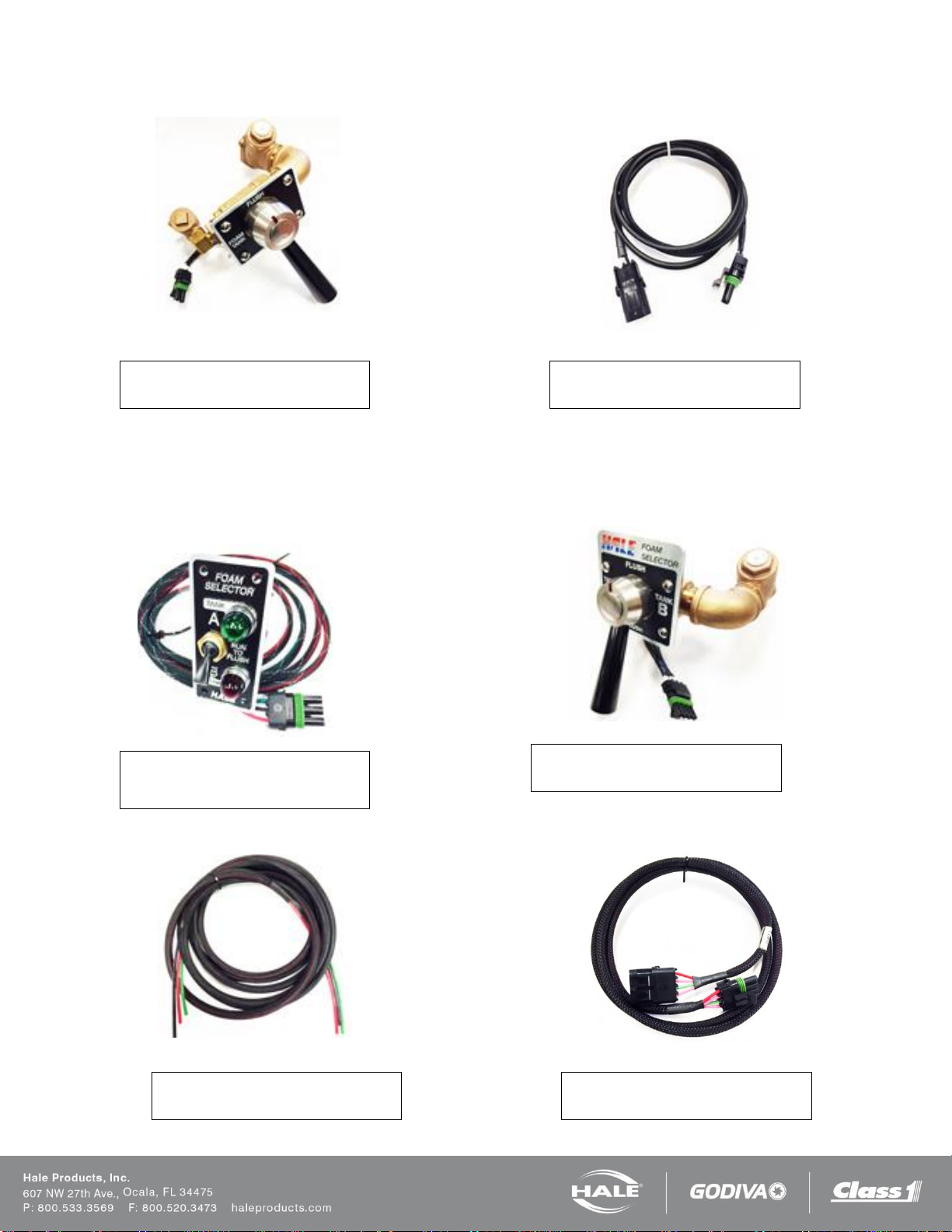
ROTARY PLUNGER PUMP (1.7 AHP, 2.1A)
The heart of the Hale SmartFOAM 2.1A and 1.7AHP
systems are an electric motor driven rotary plunger
pump. The pump is constructed of anodized aluminum
and stainless steel and is compatible with most Class
“A” foam concentrates. The pump is close coupled to the
electric motor thereby eliminating maintenance of an oil
filled gearbox.
A relief valve mounted on the foam pump and
constructed of brass, protects the foam pump and foam
concentrate discharge hoses from over pressurization
and damage.
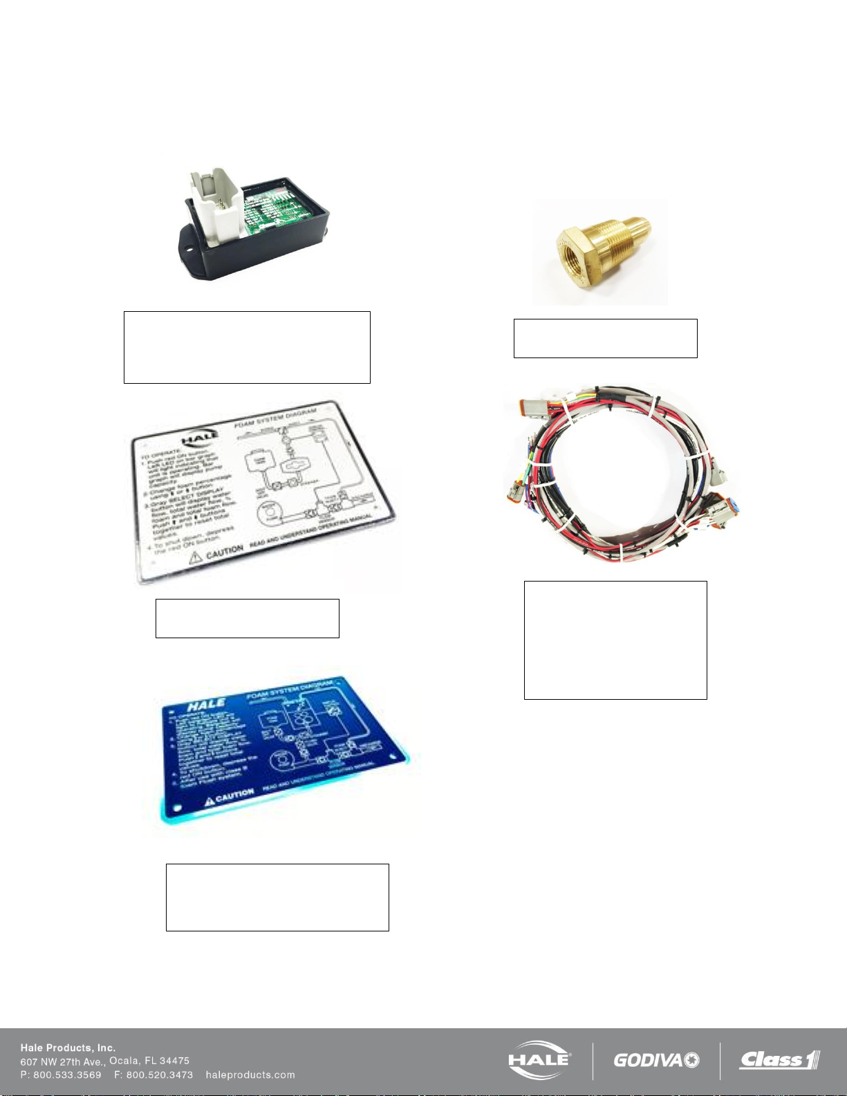
ROTARY GEAR PUMP (3.3, 5.0, 6.5)
The heart of the Hale SmartFOAM 3.3, 5.0, and 6.5
systems is an electric motor driven rotary gear pump.
The pump is constructed of bronze and stainless steel
and is compatible with almost all foam concentrates. The
pump is close coupled to the electric motor thereby
eliminating maintenance of an oil-filled gearbox. A relief
valve mounted on the foam pump and constructed of
stainless steel, protects the foam pump and foam
concentrate discharge hoses from over pressurization
and damage.
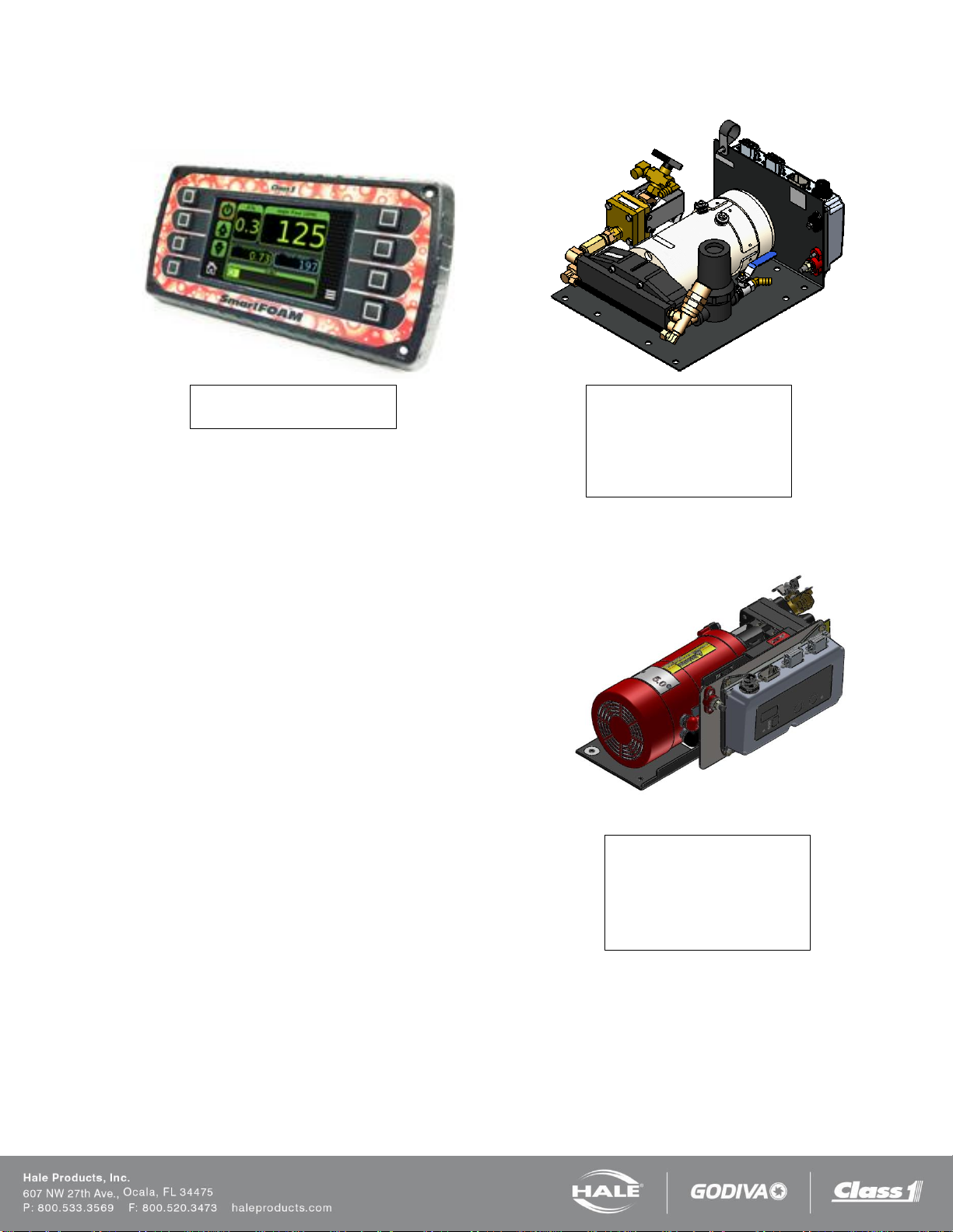
SMARTFOAM CONTROL UNIT
The control unit, mounted on the operator panel, is the
single control point for the SmartFOAM system. Press
one of the preset buttons to enable foam concentrate
Page 9
injection once water flow has been established. The 4.5”
direct sunlight viewable color display shows:
❑ Water flow rate
❑ Foam concentrate injection percentage
❑ Total water flowed
❑ Total foam concentrate used
❑ Foam pump capacity
The SmartFOAM control unit also provides plain-text
information and warnings as well as tutorials for
calibration. The user interface can be configured for the
modern SmartFOAM look or the classic FoamLogix look.
WATER FLOW SENSOR
Foam concentrate injection rate is controlled by a
computer chip in the control unit for accurate,
repeatable, reliable foam concentrate injection. A water
flow sensor constantly monitors water flow through the
discharge piping. The information from the flow sensor is
provided to the control unit by a shielded cable. When
the SmartFOAM system is activated at the control unit a
signal is sent through the control cable to the motor
controller to begin foam concentrate injection. The motor
controller then provides power to the electric motor. The
electric motor rotates the foam pump and foam
concentrate flows through the foam pump discharge to
the one piece check valve/injector fitting into the water
discharge stream.
Note: All Hale SmartFOAM Foam systems require a flow
sensor for operation.
FEEDBACK SENSOR
A feedback sensor in the foam pump discharge
measures foam concentrate flow. The water flow rate
and foam concentrate flow rate are constantly compared
by the computer chip in the control unit.
The motor speed is constantly adjusted to maintain the
operator selected foam concentrate injection rate. Since
the system is flow based, injection rate remains constant
regardless of changes in system pressure or the number
of discharges that are open (within the limits of the
system).
The maximum rated foam concentrate flow, in gallons
per minute, is denoted by the model number. Table 1:
Maximum Foam Solution Flows shows the system
capacity at various foam concentrate injection rates for
the Hale SmartFOAM systems.
Page 10
SmartFOAM
Maximum Foam Solution Flow
Injection Rate
Percent (%)
Flow rate in GPM [LPM]
1.7AHP
2.1A
3.3
5.0
6.5
Dual 6.5
0.1
1,700 [6,426]
2,100 [7,949]
3,300 [12,492]
5,000 [18,927]
6,500 [24,606]
13,000 [49,213]
0.2
850 [3,213]
1,050 [3,974]
1,650 [6,245]
2,500 [9,464]
3,250 [12,303]
6,500 [24,606]
0.3
567 [2,143]
700 [2,650]
1,100 [4,164]
1,667 [6,310]
2,167 [8,202]
4,333 [16,404]
0.5
340 [1,285]
420 [1,590]
660 [2,498]
1,000 [3,785]
1,300 [4,921]
2,600 [9,843]
1.0
170 [643]
210 [795]
330 [1,249]
500 [1,893]
650 [2,461]
1,300 [4,921]
3.0
110 [416]
167 [632]
217 [820]
433 [1,640]
6.0
55 [208]
83 [314]
108 [410]
217 [820]
Table 1: Maximum Foam Solution Flows
LOW PRESSURE STRAINER
A low pressure foam concentrate strainer is mounted at the inlet of the foam pump. The strainer protects the pump from
debris that might accumulate in the foam concentrate tank. The strainer/valve assembly has a composite non-metallic
housing with stainless steel mesh strainer element and includes a service shut-off valve.
The valve inlet offers 1/2” NPT (13 mm) threads, with a fitting to connect a 1/2” (13 mm) ID foam concentrate suction
hose.
The strainer and valve are low pressure devices and are designed for installations where the strainer IS NOT subject to
HIGH pressure flushing water.
HIGH PRESSURE STRAINERS (FS Series)
Hale FS series strainers (FS15 and FS25) are panel mounted with a 500 PSIG (34 BAR) pressure rating, suitable for use
where flushing water pressure must pass through the strainer.
The FS15 strainer uses 3/4” (19mm) NPT connection ports and a 1-1/2” NST cap. It is suitable for use with Class “A” and
low viscosity Class “B” foam concentrates.
The FS25 strainer uses 1” (25mm) NPT connection ports and a 2-1/2” NST cap. It is suitable for use with both Class “A”
and Class “B” foam concentrates.
TANK SELECTOR VALVES
SmartFOAM models 3.3, 5.0, and 6.5 may use dual foam tanks for A and B foam concentrates. Selection of the desired
foam concentrate tank with the ADT panel mounted toggle switch or MDT II selector automatically changes the foam
concentrate injection rate to the preset default rate for the selected foam tank. No further operator Intervention is required.
The ADT, MDT II and MST include the check valves and connection points to provide foam pump flushing capabilities.
Air Dual Tank Selector (ADT)
The Air Dual Tank (ADT) valve is an air operated foam tank selector valve that enables selection of foam concentrate
dependent on fire ground operational demands.
The ADT is an integral part of the foam pump and provides an electrical interlock for the low tank level sensors and
concentrate injection rate. A panel mounted selector toggle switch with indicator lights controls foam concentrate tank
selection and shows which foam concentrate tank is in use.
Manual Dual Tank Selector (MDT II)
The Manual Dual Tank (MDT II) selector valve is available for the Hale Foam systems with dual tanks. The MDT II is a
panel mounted, manually operated selector that provides selection of foam concentrate dependent on fire ground
operational demands.
The MDT II also provides an electrical interlock for the low tank level sensors and concentrate injection rate. The MDT II is
not suitable for top mount operator panel installations and some side operator panels due to gravity feed requirements of
foam concentrate to the foam pump.
Page 11
SmartFOAM
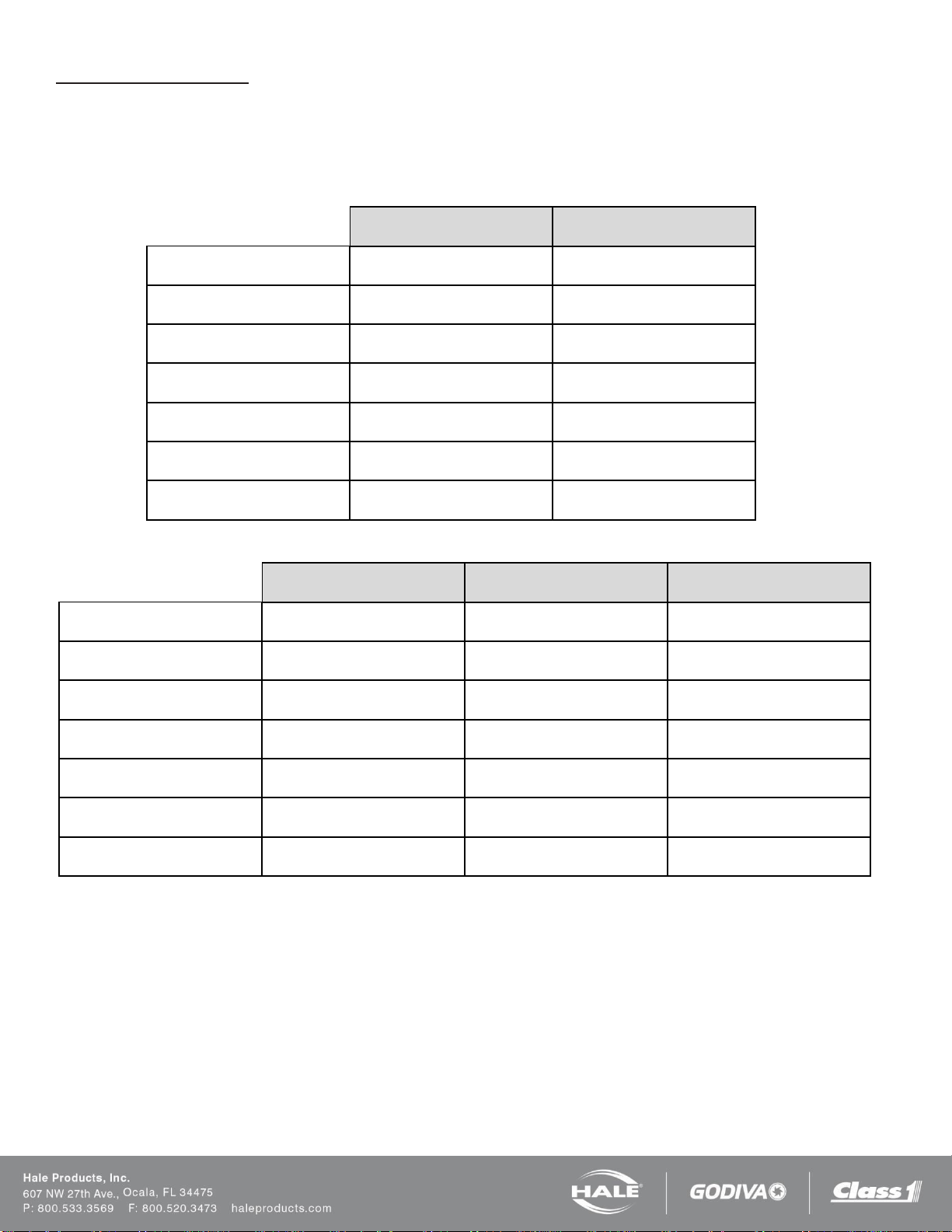
1.7AHP
2.1A
Foam Pump Type
Piston Pump, Dual Plunger
Piston Pump, Dual Plunger
Maximum Foam Concentrate
Output
1.7 GPM (6.5 LPM)
2.1 GPM (8 LPM)
Maximum System Operating
Pressure
400 PSI (27.5 BAR)
250 PSI (17 BAR)
Maximum Operating
Temperature
160°F (71°C)
160°F (71°C)
Pump Motor
0.44 HP (0.3 Kw), 12 VDC
0.44 HP (0.3 Kw), 12 VDC
Operating Ampere Draw
30 AMPS @ 12 VDC
25 AMPS @ 12 VDC
Maximum Ampere Draw
40 AMPS @ 12 VDC
40 AMPS @ 12 VDC
3.3
5.0
6.5
Foam Pump Type
Rotary Gear Positive
Displacement
Rotary Gear Positive
Displacement
Rotary Gear Positive
Displacement
Maximum Foam Concentrate
Output
3.3 GPM (13 LPM)
5.0 GPM (19 LPM)
6.5 GPM (24.6 LPM)
Maximum System Operating
Pressure
400 PSI (27.5 BAR)
250 PSI (17 BAR)
200 PSI (13.8 BAR)
Maximum Operating
Temperature
160°F (71°C)
160°F (71°C)
160°F (71°C)
Pump Motor
0.75 HP (0.6 Kw), 12 VDC
0.75 HP (0.6 Kw), 12 VDC
1.25 HP (0.9 Kw), 12 VDC
Operating Ampere Draw
30 AMPS @ 12 VDC
30 AMPS @ 12 VDC
40 AMPS @ 12 VDC
Maximum Ampere Draw
60 AMPS @ 12 VDC
60 AMPS @ 12 VDC
80 AMPS @ 12 VDC
Manual Single Tank (MST)
Single tank foam systems can be configured with a Manual Single Tank (MST) selector, which provides a flush function
connection to the foam system electronic controls.
HALE FOAM SYSTEM SPECIFICATIONS
Table 2: Specifications – 1.7 and 2.1
Table 3: Specifications – 3.3, 5.0, and 6.5
Page 12
SmartFOAM
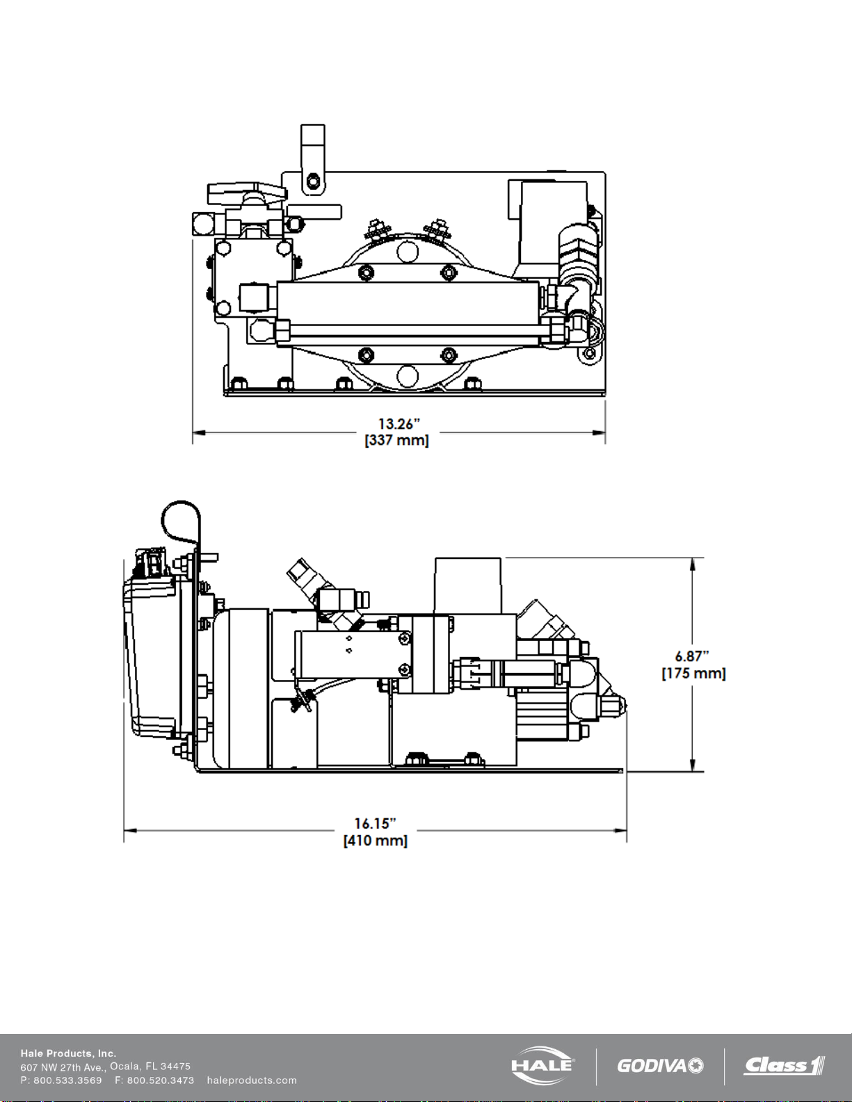
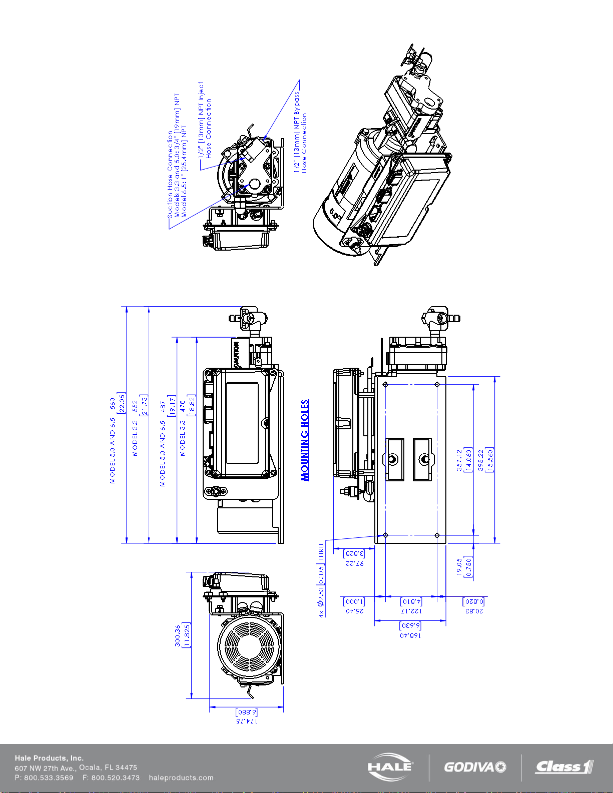
HALE FOAM PUMP DIMENSIONS
Figure 1: 1.7 and 2.1 Foam Pump Installation Envelope Dimensions
Page 13
SmartFOAM
Figure 2: 3.3 and 5.0 Foam Pump Installation Envelope Dimensions
Page 14
SmartFOAM
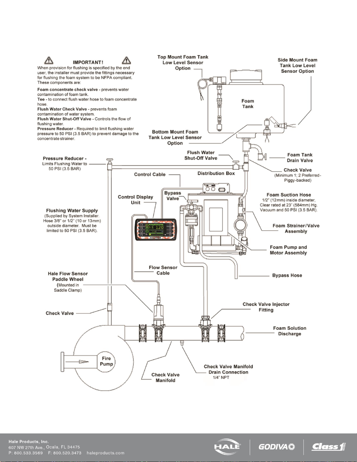
SYSTEM DIAGRAM
Figure 3: Typical Hale SmartFOAM 2.1A and 1.7AHP System
Page 15
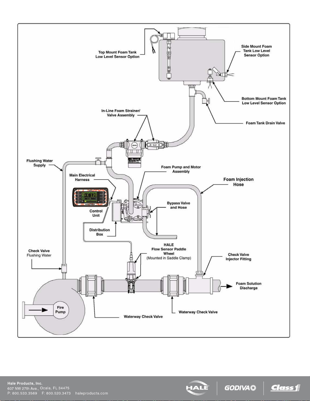
SmartFOAM
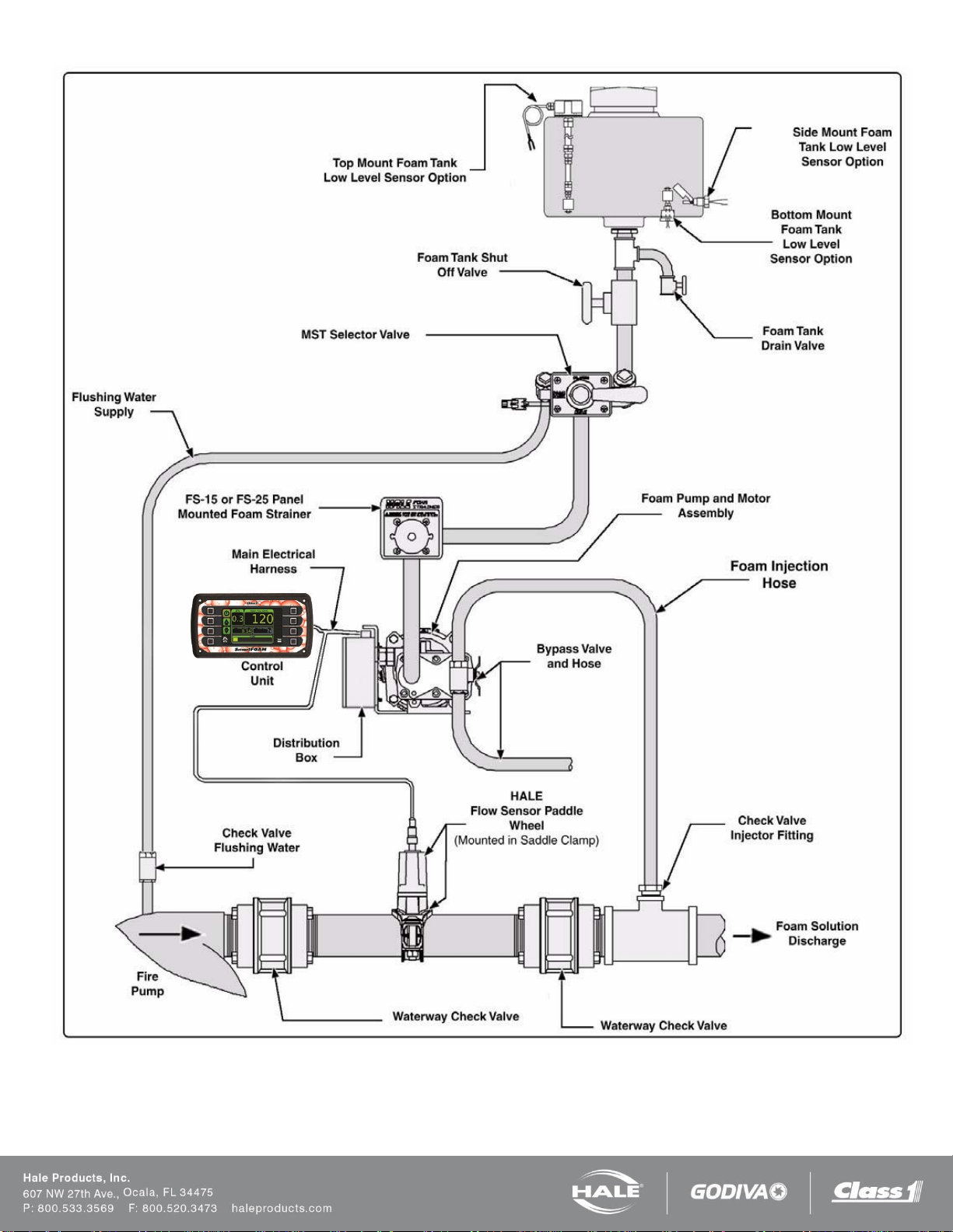
Figure 4: SmartFOAM 3.3, 5.0, 6.5 Single Tank System with In-line Strainer
Page 16
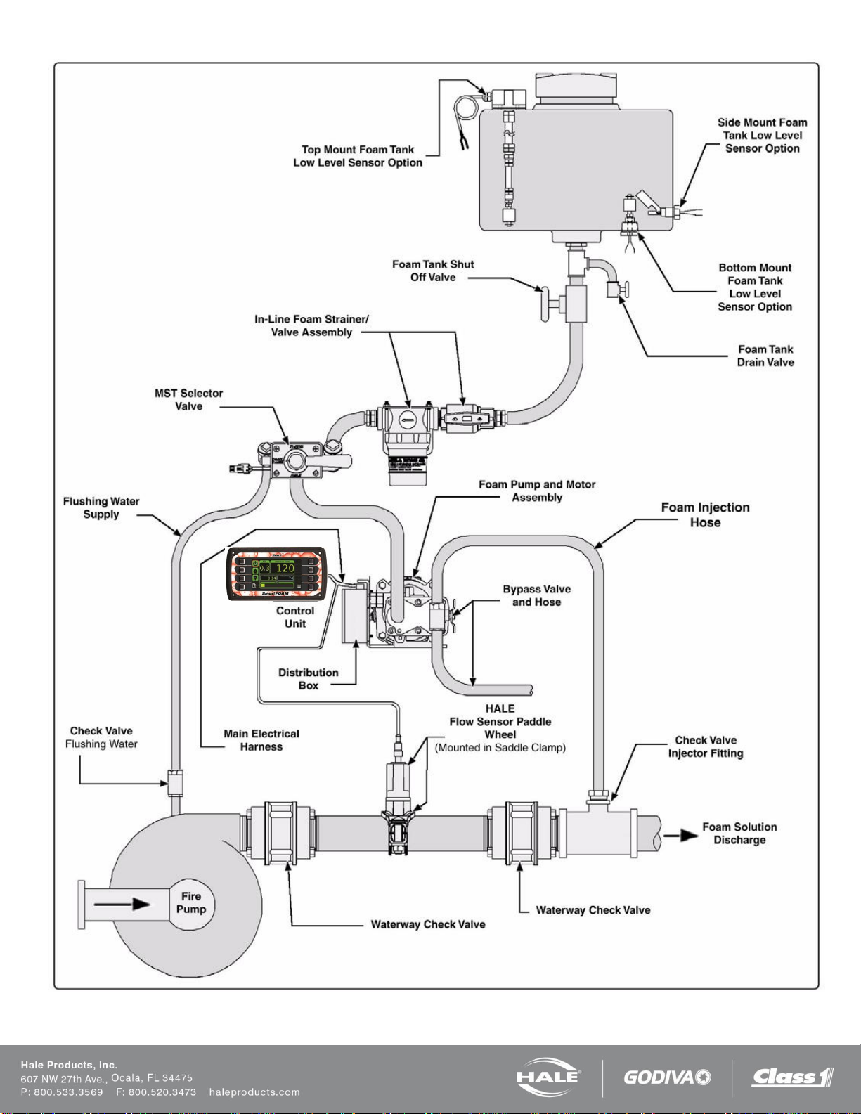
SmartFOAM
Figure 5: SmartFOAM 3.3, 5.0, 6.5 Single Tank with MST and In-line Strainer
Page 17
SmartFOAM
Figure 6: SmartFOAM 3.3, 5.0, 6.5 Single Tank with MST and FS Series Strainer
Page 18
SmartFOAM
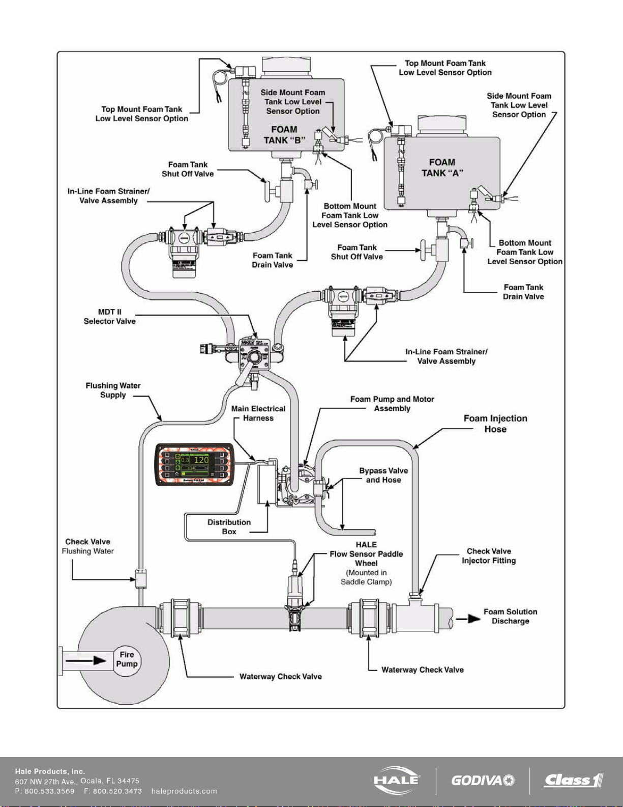
Figure 7: SmartFOAM 3.3, 5.0, 6.5 Dual Tank with MDTII and In-line Strainer
Page 19
SmartFOAM
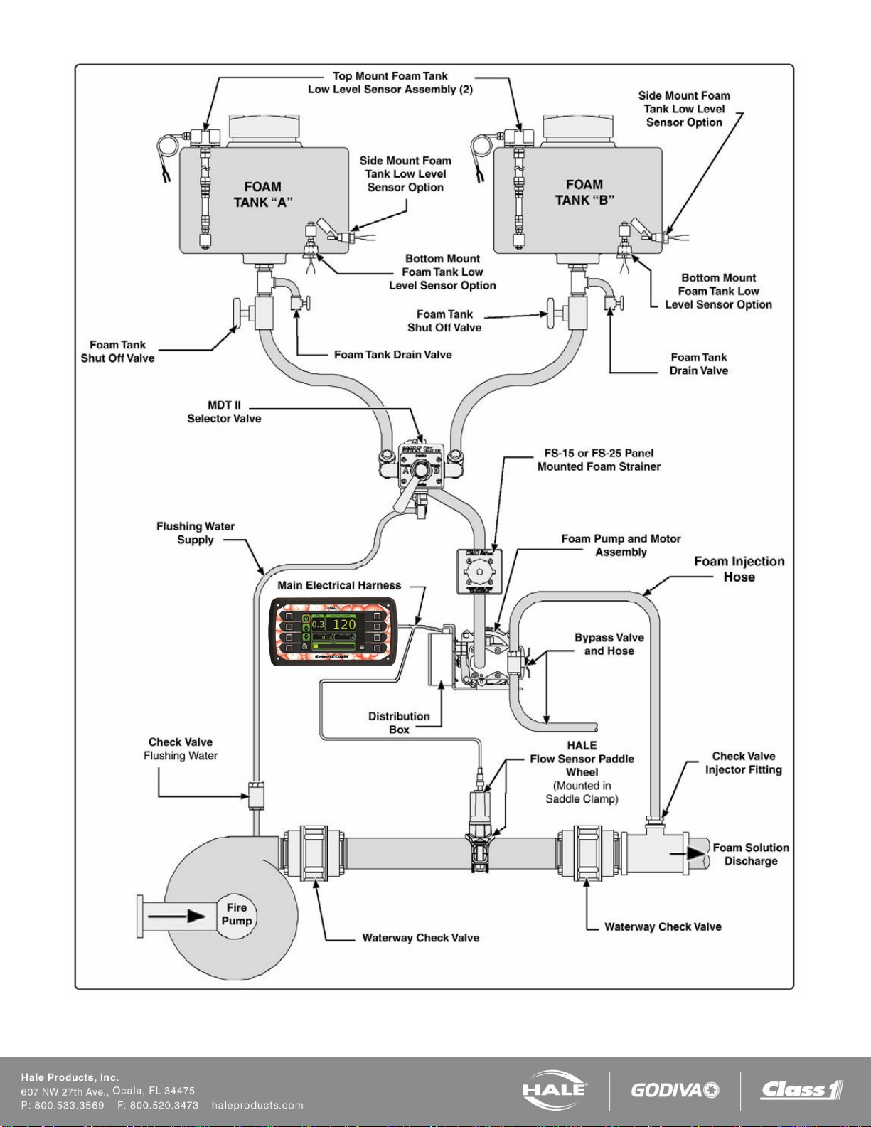
Figure 8: SmartFOAM 3.3, 5.0, 6.5 Dual Tank with MDTII and FS Series Strainer

Page 20
SmartFOAM
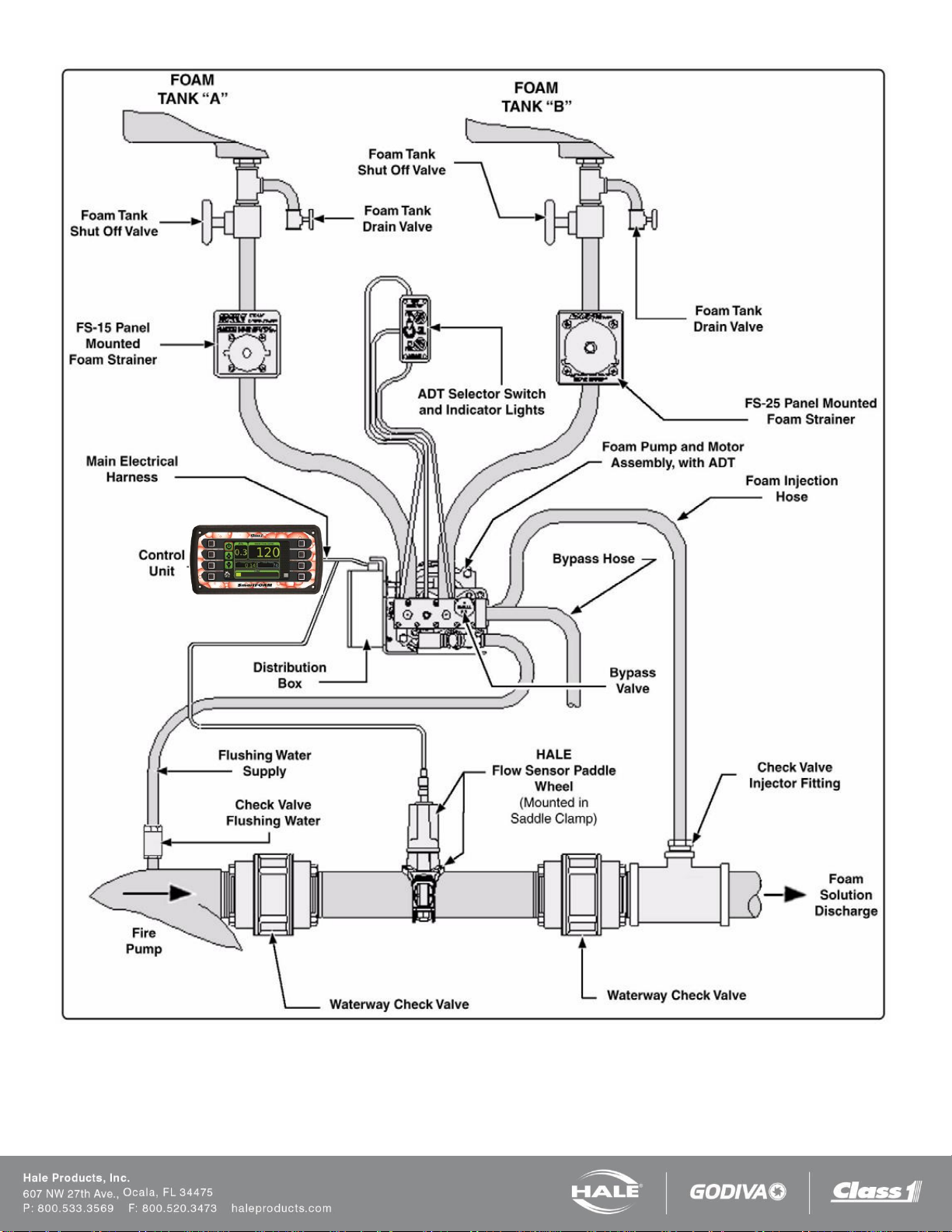
Figure 9: SmartFOAM 3.3, 5.0, 6.5 Dual Tank with ADT and In-line Strainer
Page 21
SmartFOAM
Figure 10: SmartFOAM 3.3, 5.0, 6.5 Dual Tank with ADT and FS Series Strainer
Page 22
SmartFOAM
SmartFOAM controller
610-00039
SmartFOAM Base Unit, Foam
Pump/Motor Assembly
2.1A – 12V: 115498
2.1A – 24V: 115499
1.7AHP – 12V: 119276
1.7AHP – 24V: 119277
SmartFOAM Base Unit, Foam
Pump/Motor Assembly
3.3 – 12V: 501-3120-05-0
3.3 – 24V: 501-3120-06-0
5.0 – 12V: 501-3130-05-0
5.0 – 24V: 501-3130-06-0
6.5 – 24V: 501-4480-04-0
CONTROLLER AND BASE PUMP
SmartFOAM
Check valve / Injector fitting
038-1790-00-0
SmartFOAM controller
harness
Single pump (10’x14’)
513-00101-200
Single pump (15’x19’)
513-00101-201
Dual pump
513-00074-200
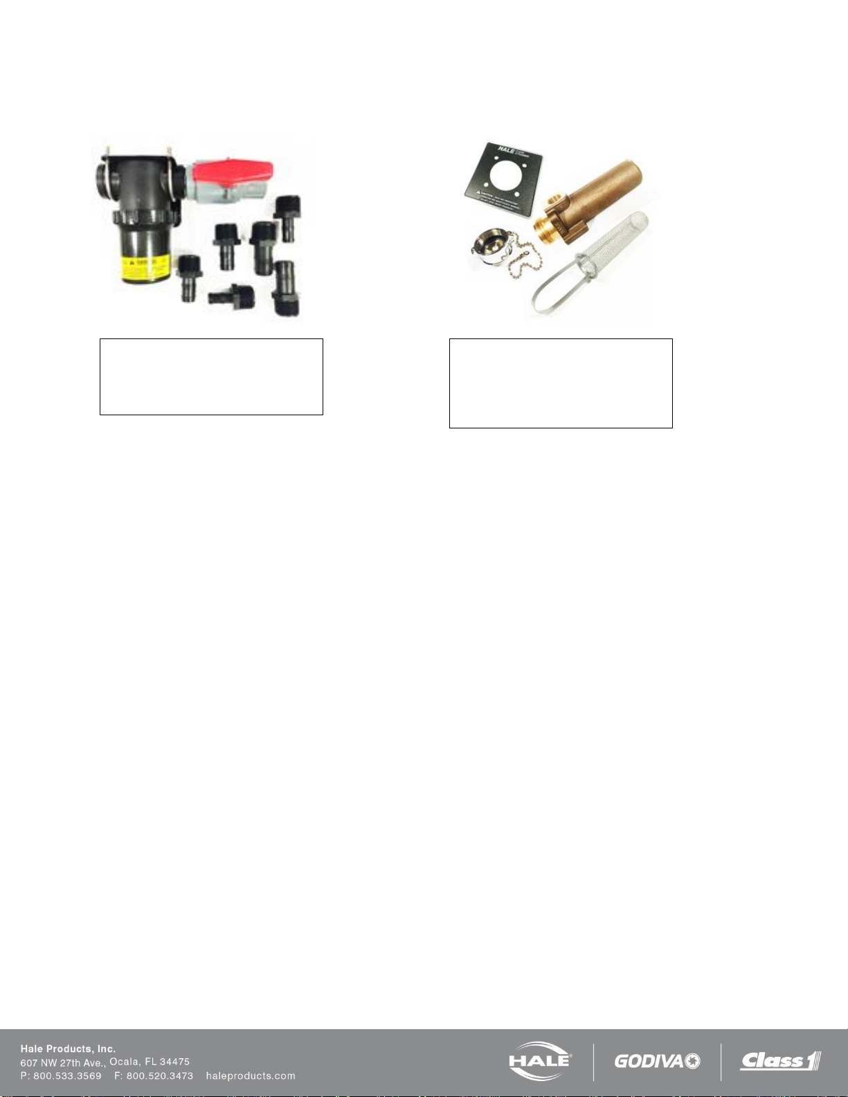
Water Flow sensor input module
610-00033
(NOT REQUIRED WITH 610-00044)
1.7, 2.1 Foam system placard
101-1630-70-0
3.3, 5.0, 6.5 Foam system placard
Inline strainer - 101-1630-58-0
MST and FS strainer – 101-1631-12-0
MDTII and FS strainer – 101-1631-07-0
Page 23
Page 24
SmartFOAM
MDTII (Manual Dual Tank)
538-1490-14-0
ADT (Air Dual Tank)
12V – 538-1640-05-0
24V – 538-1640-06-0
MDTII harness extension (6 feet)
513-0320-02-0
ADT color-coded air tubing extension
507-0380-00-0
MST harness extension (6 feet)
513-0320-07-0
MST (Manual Single Tank)
538-1490-12-0
SINGLE CONCENTRATE TANK OPTIONS
DUAL CONCENTRATE TANK OPTIONS
SmartFOAM
In-line strainer/valve assembly
510-0190-01-0
(Do not use if subject to flushing water
pressure)
FS panel mount strainers
FS-15 – 510-0150-00-0
¾” NPT threads
FS-25 – 510-0180-00-0
1” NPT threads
STRAINER OPTIONS
Page 25
Page 26
SmartFOAM
Pipe Size vs. Flow Range
Pipe size
Flow Range
GPM
LPM
1.5”
10 – 350
38 – 1,219
2.0”
20 – 550
76 – 2,082
2.5”
30 – 800
114 – 3,028
3.0”
50 – 1,250
189 – 4,731
4.0”
75 – 1,800
284 – 6,813
3” Single Check
Valve (SCV)
30 - 750
114 – 2,839
3” Dual Check Valve
(DCV)
30 - 750
114 – 2,839
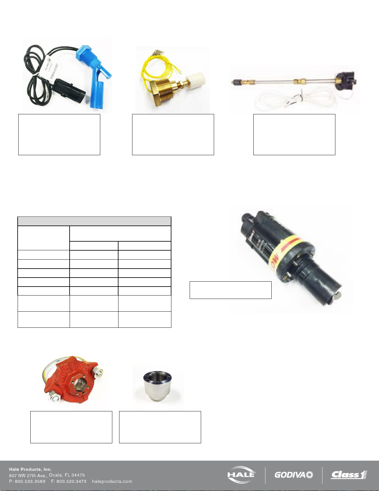
Side mount (1/2 inch NPT)
200-2110-02-0
½ inch NPT threaded bushing to
mount from outside foam tank.
Bottom mount (1 inch NPT)
200-2100-04-0
1 inch NPT threaded bushing to
mount from outside foam tank
Top mount
200-2110-06-0
Extends from 2.5 feet to 5 feet –
may be cut shorter if required.
Flow sensor weld fitting
Stainless steel – 082-3060-00-0
Steel – 309020
Aluminum - 309010
Flow sensor saddle clamp
2.0 inch – 4842010
2.5 inch – 4843010
3.0 inch – 4844010
Flow sensor paddlewheel
102714
LOW TANK SENSOR OPTIONS
FLOW SENSOR OPTIONS
Each Hale foam system requires a flow sensor for operation. Pipe size must be selected based on the minimum and
maximum water flow in the foam capable discharge. Following is a list of pipe size and rated flow ranges, along with flow
sensor saddle clamp part number. In all instances, a weld fitting may be substituted for the saddle clamp.
Table 4: Pipe Size versus Flow Range
Page 27
SmartFOAM
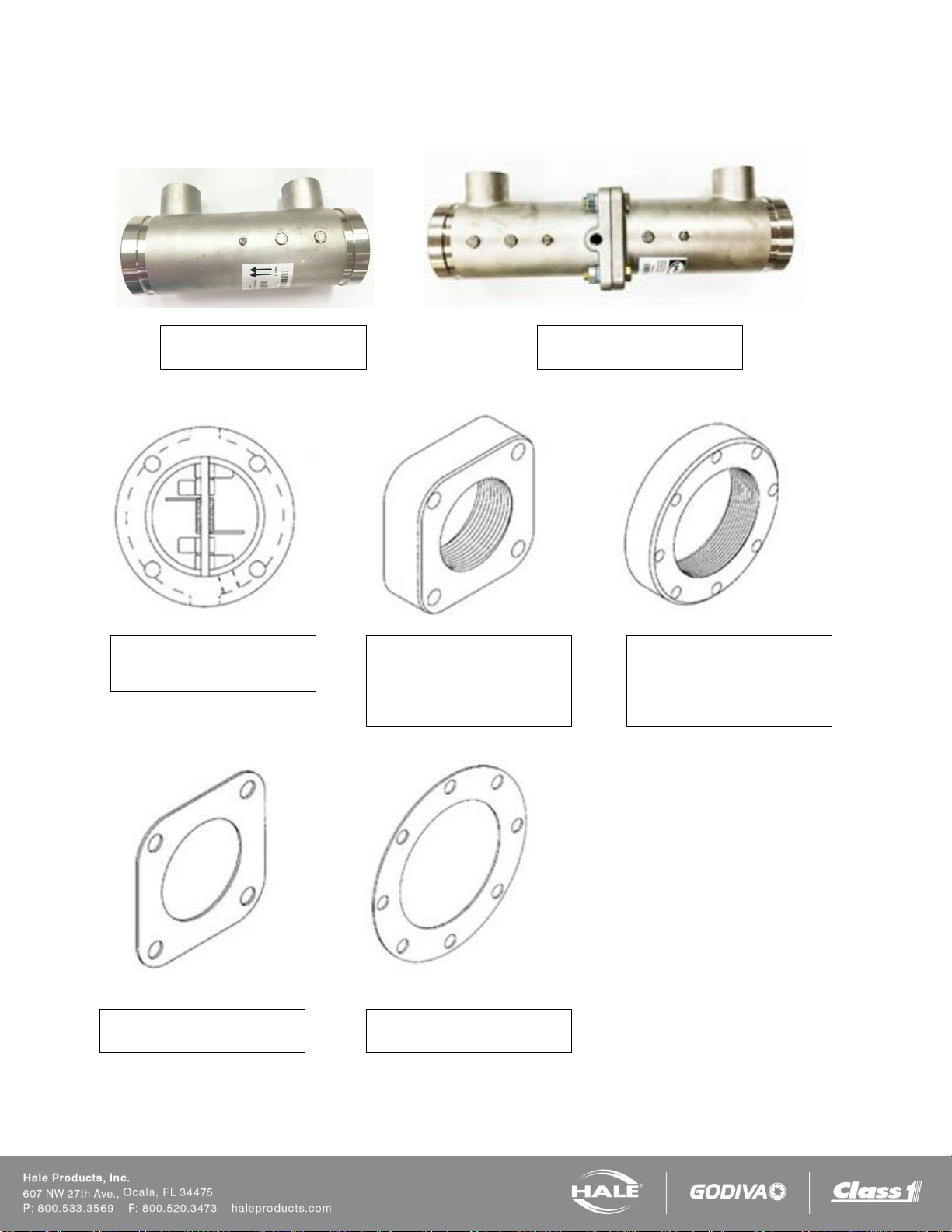
Single Check Valve (SCV)
3.0” 538-1850-00-0
Dual Check Valve (DCV)
3.0” 538-1840-00-0
Wafer Check Valve
3.0” 038-1570-06-0
4.0” 038-1570-08-0
Type 115 Flange
3.0” NPT 115-0080-00-0
2.5” NPT 115-0070-00-0
2.0” NPT 115-0060-00-0
BLANK 115-0050-00-0
Type 2433D Flange
4.0” NPT 115-0040-00-0
3.0” NPT 115-0030-00-0
2.5” NPT 115-0020-00-0
BLANK 115-0010-00-0
115 Flange Gasket
046-0050-00-0
2433D Flange Gasket
046-0040-00-0
CHECK VALVE MANIFOLDS, FLANGES AND GASKETS
The check valve manifolds include flow sensor, check valve/injector fitting and a single or dual waterway check valve
flappers. End connections for the manifolds are 3 inch Victaulic.
 Loading...