

Page 1

MUSCLE (Midship) Pumps
(“Q” Series)
Installation, Operation and
Maintenance Manual
Part 1
Hale Products Inc. u A Unit of IDEX Corporation
700 Spring Mill Avenue
Telephone: 610-825-6300
Web..........www.haleproducts.com
u Conshohocken, PA 19428 U.S.A.
u FAX: 610-825-6440
Manual p/n: 029-0020-63-0
Page 2

NOTICE !
Hale Products, Inc. (Hale) cannot assume responsibility for product f ailure resulting from improper maintenance or operation. Hale is responsibl e only to the limits
stated in the product warranty. Product specifications contained in this manual are
subject to change without notice.
All Hale products are quality components -- ruggedly designed, accurately
machined, precision inspected, carefully assembled and thoroughly tested. In
order to maintain the high quality of your unit, and to keep it in a re ady condition, it
is important to follow the instructions on ca re and operation. Proper use and go od
preventive maintenance will lengthen the life of your unit.
ALWAYS INCLUDE THE UNIT SERIAL NUMBER
IN YOUR CORRESPONDENCE.
ECO NO REV CHANGE FROM BY DATE APVD
0956 C Series Upgrade LwH 01/20/2006 MAL
Manual p/n: 029-0020-63-0, Rev. -C
Printed in U.S.A.
HALE PRODUCTS, INC.
A Unit of IDEX Corporation
Conshohocken, PA 19428 USA
DRAWN BY LwH ISSUE DATE
CHECKED BY PRW 01/20/2006
© Hale Products, Inc. 2009
NOT TO BE REPRODUCED OR USED TO
MAKE OTHER DRAWINGS OR MACHINERY.
COPYRIGHT ©
All Rights Reserved
Page 3

Table of Contents
Contents Page
MUSCLE Pump (Midship) Operation and Maintenance
1 Safety Precautions................................................................................................. 13
1.1 Definitions.........................................................................................................................13
1.2 Guidelines.........................................................................................................................14
2 Introduction...........................................................................................................19
2.1 Description........................................................................................................................19
2.2 Principle of Operation......................................................................................................19
Centrifugal Force ............. .... ... ............................................................. ... .... ... ... ................................19
Figure 2-1: Centrifugal Force - Rotating Disk.....................................................................19
Pump Stages ....................................................................................................................................20
Single-Stage...............................................................................................................................20
Figure 2-2: Water Flow, Typical Hale Single-Stage Pump .................................................20
Figure 2-3: Single-Stage Pump Overview..........................................................................21
Two-Stage..................................................................................................................................22
Volume (Parallel) Operation.......................................................................................................22
Figure 2-4: Two-Stage Pump VOLUME Operation.............................................................22
Figure 2-5: Two-Stage Pump Overview..............................................................................23
Pressure (Series) Operation ......................................................................................................24
Figure 2-6: Two-Stage Pump PRESSURE Operation........................................................24
Volume vs. Pressure Operation .................................................................................................24
Transfer Valve............................................ ... ... ... .... ...................................................................25
Choosing Volume or Pressure Operation ..................................................................................25
General Guidelines ....................................................................................................................25
2.3 Muscle Pump Components .............................................................................................26
Pump Body .......................................................................................................................................26
Qmax, Qmid, and Qtwo Pumps .................................................................................................26
Figure 2-7: Typical Midship Two-Stage Centrifugal Pump .................................................27
Qpak, Qflo and Qflo-Plus Pumps...............................................................................................27
Impeller.............................................................................................................................................27
Figure 2-8: Impeller Operation............................................................................................28
Clearance Rings ...............................................................................................................................28
2.4 Pump Seals.......................................................................................................... .............28
Packing Seals................................................................... ... ... .... ... ...................................................29
Figure 2-9: Pump Packing Seal Assembly ......................................................... ... .... ... ... ...29
Mechanical Seal .................................................. ............................................................. ................30
Figure 2-10: Mechanical Seal Assembly ............................................................................30
MUSCLE (Midship) Pumps Installation, Operation, and Maintenance Manual
p/n: 029-0020-63-0
3
Page 4

Table of Contents
Auto Lube ®......................................... ... ... ... .............................................................. ... . ..................31
Figure 2-11: AutoLube Feature....... ... .............................................................. ... ... ... .......... 31
2.5 Pump Drives ..................................................................................................................... 31
Table 2-1: Pump vs. Gearbox / Gear Ratio Comparison....................................................32
2.6 Gearbox ............................................................................................................................ 32
Figure 2-12: Typical Gearbox Overview .......................................................................... ...33
A-Series............................................................................................................................................33
G-Series............................................................................................................................................34
K-Series............................................................................................................................................34
J-Series.............................................................................................................................................34
R-Series............................................................................................................................................34
Power Shift - Optional.......................................................................................................................34
Engine Rotation Option - Qmax-U and Qtwo-U................................................................................34
Figure 2-13: Pump/Engine Rotation ...................................................................................35
HALE Power Takeoff (PTO) Driven Midship Pumps.........................................................................35
2.7 Serial Number Identification ...........................................................................................35
Figure 2-14: Typical Midship Pump Serial Number Location..............................................36
3 Accessories / Options.............................................................................................37
3.1 Anodes.............................................................................................................................. 37
Figure 3-1: Hale 1-1/4” NPT Anode....................................................................................37
3.2 Auxiliary Cooling.............................................................................................................. 38
Heat Exchanger, “K” Series ..............................................................................................................38
Figure 3-2: Model “K” Heat Exchanger...............................................................................38
3.3 Pressure and Relief Valve Control .................................................................................39
Relief Valve System..........................................................................................................................39
Figure 3-3: PMD Series Relief Valve Control (Shown).......................................................39
Thermal Relief Valves (TRV) ............................................................................................................39
Figure 3-4: Thermal Relief Valve, TRV...............................................................................40
TRV-L Kit................ ... .............................................................. ... ... ... ..........................................40
3.4 Priming Systems......................................................................................... ........... ..........41
Figure 3-5: Rotary Vane ESP Priming Pump......................................................................41
Priming Valves........................... ... ... .... ... ............................................................. ... .... ... ...................41
Figure 3-6: SPVR Priming Valve (Shown)..........................................................................42
Figure 3-7: PVG Priming Valves.........................................................................................42
3.5 Pump Shift, Automatic (VPS / KPS)................................................................................ 42
Figure 3-8: Automatic Pump Shift Overview.......................................................................43
Figure 3-9: Pump Shift Control Valve.................................................................................43
3.6 Torrent SVS Valves.......................................................................................................... 44
Figure 3-10: Typical SVS Valve Primary Components......................................................44
3.7 Additional Midship Accessories.....................................................................................44
Auxiliary Heat Exchanger / Cooler, Model K.....................................................................................44
Figure 3-11: Model “K” Heat Exchanger.............................................................................45
4
MUSCLE (Midship) Pumps Installation, Operation, and Maintenance Manual
p/n: 029-0020-63-0
Page 5

Table of Contents
Booster Pump Option, 2HP.............................................................................................................. 45
Figure 3-12: 2HP Booster Pump Option ............................... .... ......................................... 4 5
In-Line / Discharge Valves ...............................................................................................................45
Drain Valves..................................................................................................................................... 46
Suction Valves........... .............................................................. ... ... ... ................................................ 46
Figure 3-13: Master Intake Valve (MIV)............................................................................. 47
Tank Suction Valves......................................................................................................................... 47
Total Pressure Master (TPM) Relief Valve System................. ... ...................................................... 47
Figure 3-14: Hale (TPM) Total Pressure Master Relief Valve S yste m............................... 48
How the TPM Works............................................ ... ... ... .... ......................................................... 48
Figure 3-15: Typical TPM Relief Valve System, Condition 1 ....................... ...................... 50
Figure 3-16: Typical TPM Relief Valve System, Condition 2 ....................... ...................... 51
Figure 3-17: Typical TPM Relief Valve System, Condition 3 ....................... ...................... 52
4 Basic Operation .....................................................................................................53
4.1 Overview ...........................................................................................................................53
4.2 Fluid Levels ......................................................................................................................54
4.3 Stationary Pumping Operations .....................................................................................54
Pumping From a Hydrant, General Operation.................................................................................. 54
Figure 4-1: Driver’s Compartment Indicator Lights ............................................................55
Figure 4-2: Pump Operator’s Panel ................................... ................................................ 56
TPM Operation from a Hydrant ........................................................................ .... ... ... ...................... 57
Draft Limiting Factors ....................................................................................................................... 57
Pumping From Draft......................................................................................................................... 58
Pumping from On Board Water Tank (Split-Shaft PTO)................................................................... 60
4.4 Pumping In Relay.............................................................................................................62
Relay Procedures............................................................................................................................. 62
4.5 Tandem (Series) Pumping...............................................................................................64
Tandem Procedures......................................................................................................................... 64
4.6 Pump-To-Road Shift Procedures....................................................................................65
4.7 Pump and Roll............................................................................................................ ......65
4.8 Relief Valve Procedures ..................................................................................................66
Standard Relief Valve Procedures ................................................................................................... 66
TPM Relief Valve Procedures .......................................................................................................... 66
Figure 4-3: TPM / PMD Relief Valve Control ..................................................................... 67
TPM System with Engine Governor.................................................................................................67
Increasing Pressure................................................................................................................... 68
Decreasing Pressure ................................................................................................................. 68
4.9 Emergency Pump Shift Procedures...............................................................................69
4.10 Post Operation Procedures.............................................................................................69
5 Preventive Maintenance........................................................................................71
5.1 Overview ...........................................................................................................................71
MUSCLE (Midship) Pumps Installation, Operation, and Maintenance Manual
p/n: 029-0020-63-0
5
Page 6

Table of Contents
5.2 Post Operation ................................................................................................................. 71
5.3 Extreme Conditions ......................................................................................................... 71
During Freezing Weather.............................................. .... ... ... ... .......................................................71
Pumping Salt Water, Contaminated Water, or Foam Solution...................................................72
5.4 Weekly...............................................................................................................................72
Relief Valve and TPM Test...............................................................................................................73
Governor Test...................................................................................................................................73
Transfer Valve Test (Two-Stage Pumps Only).................................................................................73
Priming System Test......................................................... ... ... ... .......................................................74
Pump Shift Warning Lights ...............................................................................................................74
Valve Maintenance ....... ... ... .... ............................................................. ... ... .... ... ................................74
Intake Strainers.................................................................................................................................75
Verify All Gauges are in Working Order............................................................................................75
Operate Pump Controls ....................................................................................................................75
Inspect Water and Foam Tanks........................................................................................................75
Check Auxiliary Engine.....................................................................................................................75
5.5 Monthly ............................................................................................................................. 75
Valve Lubrication .......... ... ... .... ............................................................. ... ... .... ... ................................76
Suction Check Valve Testing, Two-Stage Pumps............................................................................76
Gearbox Lubrication .........................................................................................................................76
Packing Gland Adjustment ..................................... ............................................................. ... ..........77
Adjustment .................................................................................................................................77
Pump, Drive Line and Flange Bolts ..................................................................................................77
Priming System Test (Dry Vacuum Test)..........................................................................................78
Figure 5-1: Priming Valve Handle.......................................................................................78
5.6 Annual............................................................................................................................... 79
Replace Gearbox Oil ........................................................................................................................80
Relief Valve System Check ..............................................................................................................80
Check Drain Lines to Multi-Drain......................................................................................................81
Clean Priming Pump.........................................................................................................................81
MIV Relief Valve Test and Adjustment.............................................................................................81
Performance Testing Overview ....................... .... ... ... ... .... ........................................................... .....82
Table 5-1: Pump Ratings (GPM / LPM)..............................................................................82
Tank-to-Pump Flow Rate Test ...................................................................................................82
Performance Testing Equipment and Mater ials............................. ... ... .............................................83
Performance Testing ................................. ... ... .... ... ... .......................................................................84
Thermal Relief Valve Test ...............................................................................................................85
Table 5-2: Maximum Pump Run Time................................................................................85
Repacking the Seal...........................................................................................................................85
Figure 5-2: Pump Packing Seal Assembly ............................................... .... ... ... ... ... .......... 86
Worn Clearance Rings and Impeller Hubs.... ... .... ... ... ............................................................. .... ... ...86
Anode Check ............. ... ... ... .............................................................. ... ... ... .... ...................................87
Figure 5-3: Hale 1-1/4” NPT Anode....................................................................................87
Figure 5-4: Muscle Pump Service Chart, Part 1 of 3..........................................................88
6
MUSCLE (Midship) Pumps Installation, Operation, and Maintenance Manual
p/n: 029-0020-63-0
Page 7

Table of Contents
Figure 5-5: Muscle Pump Service Chart, Part 2 of 3.......................................................... 89
Figure 5-6: Muscle Pump Service Chart, Part 3 of 3.......................................................... 90
Midship Pump Maintenance Check List.............................................................91
Recommended “Weekly” Procedures......................................................................................91
Recommended “Annual” Procedures......................................................................................92
6 Troubleshooting.....................................................................................................93
Table 6-1: Muscle (Midship) Pump Troubleshooting........................................................ 93
PTO Will Not Engage. ...................................................................................................... 93
Pump Will Not Engage.....................................................................................................93
Pump Loses Prime or Will Not Prime............................................................................... 94
Insufficient Pump Capacity, Single Stage. ....................................................................... 96
Leak at Pump Packing. .................................................................................................... 97
Remote Control Difficult to Operate. ................................................................................ 97
Engine Speeds Too HIGH for Required Capacity or Pressure. ....................................... 98
Cavitation .........................................................................................................................99
Relief Valve Does Not Relieve Pressure When Relief Valves are Closed.......................99
Relief Valve Does Not Recover and Return to Original Pressure Setting After Opening
Valves............................................................................................................................... 99
Relief Valve Opens When Control Valves are Locked Out..............................................99
Unable to Obtain Proper Setting on Relief Valves. ................................. ... ... .................100
Discharge Valves Are Difficult to Operate.................................. ... ................................. 100
Water/Moisture in Pump Gearbox.................................................................................. 101
Rotation Symptoms........................................................................................................ 101
7 Repair and Corrective Maintenance .................................................................103
7.1 Overview .........................................................................................................................103
7.2 General Repair Guidelines ............................................................................................103
Before You Begin... ........................................................................................................................ 103
Table 7-1: Typical Torque Values Chart ............................... .... ... ... ... .............................. 105
Remove the Gearbox Assembly..................................................................................................... 105
7.3 Cleaning and Inspection Guidelines ............................................................................ 106
Bearings......................................................................................................................................... 106
Tools Required...............................................................................................................................107
7.4 Removing the Pump Assembly ....................................................................................108
Figure 7-1: Typical Muscle (Midship) Pump Overview.....................................................108
Figure 7-2: Lifting Eyebolt Attachment Layout................................................................. 109
Installing the Assembly to the Apparatus .......................................................................................110
7.5 Removing the Gearbox..................................................................................................110
G Series Gearbox...... ... .... ... ............................................................. ... .... ... ... ................................. 110
Figure 7-3: Typical G Series Gearbox Removal .............................................................. 111
Removal - G Series .................................................................................................................111
Installation - G Series ............................................................. ................................................. 112
MUSCLE (Midship) Pumps Installation, Operation, and Maintenance Manual
p/n: 029-0020-63-0
7
Page 8

Table of Contents
J Series Gearbox............................................................................................................................112
Removal - J Series...................................................................................................................112
Figure 7-4: Typical J Series Gearbox Removal................................................................113
Installation - J Series................................. .... ... ... ............................................................. ........113
K Series Gearbox ...........................................................................................................................114
Removal - K Series ..................................................................................................................114
Installation - K Series .................... ... ... ............................................................. .... ... ... ... ...........115
7.6 QMID/QMAX/QTWO AutoLube ® Service .................................................................... 115
Figure 7-5: AutoLube Assembly Overview.......................................................................116
7.7 Impeller Assembly ......................................................................................................... 118
QMID/QMAX/QTWO Removing Impeller and Clearance Rings.....................................................118
Figure 7-6: Qmax / Qtwo Assembly Overview..................................................................119
Disassembly - QMAX/QMID Single-Stage Pump...........................................................................120
Assembly - QMAX/QMID Single-Stage Pump................................................................................121
Disassembly - QTWO Two-Stage Pump........................................................................................122
Assembly - QTWO Two-Stage Pump .............................................................................................123
Inspection – Clearance Rings.........................................................................................................124
Figure 7-7: Clearance Ring and Impeller ID / OD Measurement......................................124
Installing the Impeller and Clearance Rings ...................................................................................125
8 Packing and Mechanical Seal Maintenance......................................................127
8.1 Packing Seal Replacement............................................................................................ 127
Figure 8-1: Pump Packing Seal Overview............................................. ... .... ... .................127
Figure 8-2: Packing / Mechanical Seal Assembly Overview.............................................128
8.2 Mechanical Seal Replacement...................................................................................... 129
Qmax and Qtwo Pumps with G Series Gearbox.............................................................................129
Figure 8-3: Qmax, Qmid, and Qtwo Mechanical Seal Assembly Overview......................130
Removing the Seal...................................................................................................................130
Figure 8-4: Mechanical Seal Overview / Replacement.....................................................131
Installing the Seal.....................................................................................................................132
Qmax and Qtwo Pumps with K Series Gearbox.............................................................................134
Removing the Seal...................................................................................................................134
Figure 8-5: QmaxK and QtwoK Mechanical Seal Assembly Overview.............................135
Figure 8-6: Mechanical Seal Overview / Replacement.....................................................135
Installing the Seal.....................................................................................................................136
Impeller Assembly and Mechanical Seal Qflo, Qflo-Plus and Qpak Pump.....................................138
Removing the Mechanical Seal................................................................................................138
Figure 8-7: Qflo / Qflo-Plus / Qpak Mechanical Seal Assembly Overview .......................139
Figure 8-8: Mechanical Seal Overview / Replacement.....................................................140
Installing the Seal ...........................................................................................................................140
K-Gearbox Mechanical Seal............................ .... ... ............................................................. ... ........142
Figure 8-9: Housing on shaft ............................................................................................143
Figure 8-10: Retaining ring .......................... ... .... ............................................................. .143
Figure 8-11: Seal seat into cover........................................ ... ... ........................................144
8
MUSCLE (Midship) Pumps Installation, Operation, and Maintenance Manual
p/n: 029-0020-63-0
Page 9

Table of Contents
Figure 8-12: Pump shaft gear and top space installed..................................................... 145
Figure 8-13: Install bearing lock nut................................................................................. 146
9 Gearbox Maintenance.........................................................................................149
9.1 G Series Gearbox Maintenance ....................................................................................149
Disassembly................................................................................................................................... 149
Intermediate and Sliding Gear Shaft Assemblie s ................................................................... . 149
Figure 9-1: Intermediate Shaft and Sliding Gear, Typical G Series Gearbox .................. 149
Tail Shaft Assembly................................................................................................................. 150
Figure 9-2: Tail Shaft Assembly .......................................................................................150
Power Gearshift Assembly ...................................................................................................... 151
Figure 9-3: Power Gearshift Assembly ............................................................................152
Sliding Gear and Fork..............................................................................................................152
PTO Drive Option, Qflo / Qflo Plus / Qpak Series Pump......................................................... 153
Figure 9-4: PTO Drive Option ..........................................................................................154
Assembly........................................................................................................................................ 154
Gearshift Cap........................................................................................................................... 154
Sliding Gear Assembly ............................................................................................................ 154
Tail Shaft and Gear Shift Assemblies...................................................................................... 155
PTO Drive Option .................................................................................................................... 156
Intermediate Shaft Assembly...................................................................................................156
9.2 J Series Gearbox Maintenance .....................................................................................157
Disassembly................................................................................................................................... 157
Idler Shaft Disassembly.......... ... ... ............................................................. .... ... ... ... .................157
Figure 9-5: Typical J Series Gearbox Assembly.............................................................. 158
Input Shaft Disassembly..........................................................................................................159
Assembly and Installation...............................................................................................................159
Input Shaft Assembly...............................................................................................................159
Idler Shaft Assembly............................................ ... ... .............................................................. 160
9.3 K Series Gearbox Maintenance ....................................................................................161
Oil seals (Input/Tail Shafts) .............. ... ... ... .... ............................................................. ... ... .... ..........161
Figure 9-6: Oil Seal Replacement.................................................................................... 161
Tail Shaft Assembly.......... ... ... ... .............................................................. ... ... ... .... .......................... 162
Figure 9-7: Tail Shaft Assembly .......................................................................................162
Removal And Disassembly............................................................................................... ... ... . 162
Inspection ................................................................................................................................163
Reassembly and Installation....................................................................................................163
Figure 9-8: Shaft End Gap ............................................................................................... 164
Input Shaft.............. ............................................................. .... ... ... ... .............................................. 165
Figure 9-9: Input Shaft Assembly..................................................................................... 165
Removal and Disassembly ..................... ... ............................................................. ... .... ... ... ....165
Inspection ................................................................................................................................166
Reassembly and Installation....................................................................................................166
KPS Power Shift Assembly............................................................................................................ 167
MUSCLE (Midship) Pumps Installation, Operation, and Maintenance Manual
p/n: 029-0020-63-0
9
Page 10

Table of Contents
Figure 9-10: KPS Shift Cylinder Assembly.......................................................................167
Removal...................................................................................................................................167
Installation................................................................................................................................168
KPS Shift CAP and Switch .............................................................................................................169
Figure 9-11: KPS Shift Cap Assembly..............................................................................169
Removal...................................................................................................................................169
Installation................................................................................................................................169
Gear Shift Fork ...............................................................................................................................170
Removal...................................................................................................................................170
Installation................................................................................................................................170
Idler Shaft......................................... ... ............................................................. .... ... ... . .............171
Figure 9-12: Idler Shaft Assembly....................................................................................171
Removal...................................................................................................................................171
Inspection.................................................................................................................................172
Installation................................................................................................................................172
10 Installation............................................................................................................173
10.1 Overview......................................................................................................................... 173
10.2 Mounting.........................................................................................................................173
Mounting Holes...............................................................................................................................173
Figure 7-1: Lifting Eyebolt Attachment Layout..................................................................174
10.3 Driveline Issues.............................................................................................................. 175
Drive Line and Flange Bolts............................................................................................................175
Issues .............................................................................................................................................175
Table 10-1: Maximum Recommended Driveline Lengths.................................................176
10.4 Plumbing Connections..................................................................................................177
10.5 Panel Mounted Accessories ......................................................................................... 177
10.6 Fluid Levels .................................................................................................................... 177
Appendix A:Glossary.................................................................................................179
Appendix B: Measurements and Conversions .........................................................183
Table B-1: Conversion Chart ............................................................................................183
Appendix C:Alternate Lubricant Manufacturers...................................................185
Table C-1: Alternate Lubricant Manufacturers..................................................................185
Appendix D:Lube and Sealant Specifications ........................................................187
10
Table D-1: Oil Capacity and Recommendation ................................................................187
Grease............................................................................................................................................188
Loctite Sealant................................................................................................................................188
Oil ...................................................................................................................................................188
Recommended Cleaners.............................. ... .... ............................................................. ... ... ........188
MUSCLE (Midship) Pumps Installation, Operation, and Maintenance Manual
p/n: 029-0020-63-0
Page 11

Table of Contents
Appendix E: Hose Friction Loss ...............................................................................189
Table E-1: Hose Friction Loss (PSI (kPa) / 100 Feet)......................................................189
Appendix F: Nozzle Size vs. Pressure .......................................................................191
Table F-1: Nozzle Flow and Pressure Ratings (Part 1).................................................... 191
Table F-2: Nozzle Flow and Pressure Ratings (Part 2).................................................... 192
Appendix G:Cavitation..............................................................................................193
Figure G-1: Sample, Cavitation Regions.......................................................................... 193
G.1 Process of Cavitation ....................................................................................................193
G.2 Warning Signs of Cavitation (Discharge and Gauges)...............................................194
Discharge Pressure........................................................................................................................ 194
Vacuum Compound Gauge............................................................................................................ 194
G.3 Eliminating Cavitation ...................................................................................................194
During Operations .................. ... .... ... ............................................................. ... .... ... ... .................... 195
Table G-1: Lift Loss from Elevation.................................................................................. 195
Table G-2: Lift Loss from Temperature............................................................................ 195
Table G-3: Lift Loss from Barometric Reading................................................................. 196
Preventive Measures......................................................................................................................196
Table G-4: Hose Size vs. Pump Rating Capacity ............................................................ 196
Strainers.........................................................................................................................................197
Appendix H:Midship Flow Rates..............................................................................199
Table F-1: Midship Flow Rates ........................................................................................199
Express Warranty ...............................................................................................201
Drawing Package .......................................................................................................203
Part 2 (Section 8) ........................................................................................................203
MUSCLE (Midship) Pumps Installation, Operation, and Maintenance Manual
p/n: 029-0020-63-0
11
Page 12

Table of Contents
12
MUSCLE (Midship) Pumps Installation, Operation, and Maintenance Manual
p/n: 029-0020-63-0
Page 13

1 Safety Precautions
IMPORTANT!
DANGER!
W ARNING!
CAUTION!
HALE PUMPS ARE DESIGNED FOR OPTIMUM SAFETY OF ITS OPERATORS. FOR
ADDED PROTECTION, PLEASE FOLLOW THE SAFETY GUIDELINES LISTED IN THIS
SECTION AND ADHERE TO ALL WARNING, DANGER, CAUTION AND IMPORTANT
NOTES FOUND WITHIN THIS MANUAL.
ALL SUPPLIED DOCUMENTATION MUST BE CAREFULLY READ, UNDERSTOOD AND
STRICTLY ADHERED TO BY ALL INSTALLERS AND OPERATORS BEFORE ATTEMPTING TO INSTALL OR OPERATE THE PUMP.
WHEN DEVELOPING DEPARTMENTAL APPARATUS OPERATING PROCEDURES,
INCORPORATE THE WARNINGS AND CAUTIONS AS WRITTEN.
Safety Precautions
Hale is a registered trademark of Hale Products, Incorporated. All other brand and product names are
the trademarks of their respective holders.
1.1 DEFINITIONS
DANGER - IMMEDIATE HAZARD WHICH WILL RESULT IN SE VERE PERSONAL INJURY
OR DEATH IF THE WARNING IS IGNORED.
WARNING - HAZARD S OR UNSAFE PRACTICES WHICH COULD RESULT IN SEVERE
PERSONAL INJURY OR DEATH IF THE WARNING IS IGNORED.
CAUTION - HAZARDS OR UNSAFE PRACTICES WHICH COULD RESULT IN MINOR OR
MODERATE PERSONAL INJURY IF THE WARNING IS IGNORED.
MUSCLE (Midship) Pumps Installation, Operation, and Maintenance Manual
p/n: 029-0020-63-0
13
Page 14

Safety Precautions
IMPORTANT!
IMPORTANT!
IMPORTANT - PRACTICES WHICH COULD RESULT IN DAMAGE TO THE APPARATUS
OR OTHER PROPERTY.
1.2 GUIDELINES
THE PROCEDURES IN THIS MANUAL ARE GENERAL OPERATING PROCEDURES.
THEY DO NOT REPLACE THE PROCEDURES, POLICIES, OR GUIDELINES ESTABLISHED BY THE AUTHORITY HAVING JURISDICTION, NOR DO THEY REPLACE THE
RECOMMENDATIONS AND PROCEDURES PROVIDED IN THE APPARATUS MANUFACTURER'S MANUAL.
REFER TO THE PROCEDURES PR OVIDED BY THE AUTHORITY HAVING JURISDICTION
ON SETTING WHEEL CHOCKS (TO PREVENT ANY MOVEMENT OF THE APPARATUS),
AS WELL AS LAYOUT AND CONNECTION OF HOSES, VALVES AND DRAIN COCKS.
ALL FASTENERS ON THE HALE PUMP AND GEARBOX ASSEMBLY ARE SELECTED
FOR THEIR APPLICATION. HALE PRODUCTS DOES NOT RECOMMEND REPLACING
FASTENERS WITH ANYTHING OTHER THAN HALE PART NUMBERS PROVIDED.
REPLACING WITH A WEAKER ALTERNATIVE POSES A SERIOUS SAFETY RISK.
ALL FASTENERS MUST BE INSTALLED WITH A LOCKING ANAEROBIC ADHESIVE/
SEALANT, SUCH AS LOCTITE
Use care when removing the pump assembly from its packaging to prevent per-
®
#242 OR EQUIVALENT.
sonal injury and/or damage to the system.
Use all mounting bolt holes provided on the gearbox and/or the pump to support
the assembly. See the pump assembly plate drawing, located at the back of this
manual, for additional installation information.
Installation should be performed by a trained and qualified installer, such as your
authorized Hale representative. Be sure the installer has sufficient knowledge,
experience and the proper tools before attempting any installation.
14
MUSCLE (Midship) Pumps Installation, Operation, and Maintenance Manual
p/n: 029-0020-63-0
Page 15

Safety Precautions
W ARNING!
W ARNING!
THE HALE PUMP AND GEARBOX ASSEMBLY CAN BE HEAVY AND BULKY. ADDING
ACCESSORIES TO THE SYSTEM ALSO INCREASES THE WEIGHT. CHECK YOUR BILL
OF LADING FOR THE APPROXIMATE WEIGHT.
BE CERTAIN TO USE PROPER LIFTING SUPPORT DEVICES (I.E., OVERHEAD CRANE,
JACKS, CHAINS, STRAPS, ETC.) CAPABLE OF HANDLING THE LOAD WHEN REMOVING OR INSTALLING THE HALE PUMP AND GEARBOX ASSEMBLY.
The installer is responsible for observing all instructions and safety preca utions in
his or her daily routine as dictated by regional safety ordinances or departmental
procedures.
Fluids - To meet various shipping regulations, oil is drained from the gearbox res-
ervoir prior to shipping from the factory.
At installation and before operation, oil must be added to the appropriate levels.
(See Section 4, heading “ Gearbox Lubrication,” on page 76.)
See separate documentation provided with the engine and pump and gearbox
assemblies for proper fluids to use and quantities required.
DO NOT permanently remove or alter an y protectiv e f eature , guard or insulating
devices, or attempt to operate the system when these guards are removed.
Doing so voids the Hale pump warranty. Also see heading “Express Warranty” on
page 201.
Any of the above could aff ect system capacity and/or saf e opera tion of the system
and is a serious safety violation which could cause personal injury or could affect
safe operation of the pump.
NO MODIFICATIONS MAY BE MADE TO THE HALE PUMP AND GEARBOX ASSEMBLY
WITHOUT PRIOR WRITTEN PERMISSION FROM:
Hale Products, Incorporated
Fire Suppression Division
700 Spring Mill Avenue
Conshohocken, PA 19428 U.S.A.
Telephone: 610-825-6300
Fax: 610-825-6440
Web: www.haleproducts.com
MUSCLE (Midship) Pumps Installation, Operation, and Maintenance Manual
p/n: 029-0020-63-0
15
Page 16

Safety Precautions
W ARNING!
Rotating drive line parts can cause injury. Be extremely careful that NO part of
your body (head, feet, arms, legs, fingers, hair, etc.) is in an area of rotating parts
where you could be subject to injury.
Make sure everyone is clear of the apparatus before shifting to the PUMP posi-
tion. Verify the parking brake is set and the wheels are chocked to prevent any
movement of the apparatus.
Make sure proper personal protective equipment is used when operating or ser-
vicing the apparatus.
BE SURE TO WEAR SAFETY GLASSES WHEN REMOVING AND/OR INSTALLING
FORCE (PRESS) FITTED PARTS. WEAR PROTECTIVE, HEAT-RESISTANT GLOVES
WHEN HANDLING PARTS THAT REQUIRE HEATING FOR INSTALLATION AND/OR
REMOVAL. FAILURE TO COMPLY MAY RESULT IN SERIOUS EYE OR HAND INJURY.
DO NOT OVERHEAT PARTS CONSTRUCTED OF BRONZE (E.G. IMPELLER). OVERHEATING (PART TURNS RED OR BLUE) CAN WEAKEN THE PART AND IT MUST THEN
BE REPLACED.
DO NOT operate the system at pressures higher than the maximum rated pres-
sure. Alwa ys use the lo west possib le relief v alv e settings to enhance operator and
equipment safety. Also see Section 2 “Introduction” on page 19 for additional information.
Relieve all system pressure, then drain all water from the system before servicing
any of its component parts.
Use only pipe, hose and fittings which are rated at or above the maximum pres-
sure rating at which the water pump system operates.
Per NFPA 1962 requirements, large diameter hose, marked “supply Hose 3-1/2” to
5” (89 - 127 mm) diameter” shall not be used at operating pressures exceeding
185 PSI (1,276 kPa). Large diameter hose, marked “Supply Hose 6” (150 mm)
diameter” shall not be used at operating pressures exceeding 135 PSI (931 kPa).
If leakage from the drain hole in the pump head is noticed or suspected, the
mechanical seal must be inspected and/or replaced.
If a pump is operated without water for extended periods, or without discharging
water, it could overheat. This can damage the mechanical seal, impeller or the
drive mechanism.
16
DO NOT attempt to pump until all the GREEN pump indicators in the cab and
panel are ON. Also see Section 4 “Basic Operation” on page 53 for additional
information.
DO NOT advance the throttle unless the OK TO PUMP indicator is ON. Also see
Section 4 “Basic Operation” on page 53 for additional
MUSCLE (Midship) Pumps Installation, Operation, and Maintenance Manual
p/n: 029-0020-63-0
Page 17

Safety Precautions
information.
DO NOT leav e the cab , after selecting the PUMP mode , until all the GREEN pump
indicators in the cab and panel are ON. Also see Section 4 “Basic Operation” on
page 53 for additional info rmation.
DO NOT attempt emergency manua l shift procedures while the engin e is running.
Also see Section 4 “Basic Operation” on page 53 for additional information.
Never attempt to shift the pump (PUMP-to-R OAD, vise versa) while the app aratus
transmission is in gear. Always shift the transmission to NEUTRAL (N) and verify
the speedometer is at ZERO (0) before shifting the pump. Also see Section 4
“Basic Operation” on page 53 for additional information.
DO NOT reduce the pressure on the INTAKE gauge below zero (0). Serious dam-
age to the water main could result.
Some vehicles maintain air on the shift cylinder continuously regardless of trans-
mission setting, and some only have air applied when the vehicle transmission is
in NEUTRAL.
Use caution when servicing.
Use only PAC-EASE Rubber Lubricant Emulsion (or equal) on the rubber
mechanical seal parts to ease installation. DO NOT use other lubricant types as
damage to the mechanical seal and seat could occur.
Before connecting any cord sets or wiring harnesses, inspect the seal washer in
the connector.
If the seal washer is missing or damaged, water can enter the connector causing
corrosion. This could resulting in possible system failure.
MUSCLE (Midship) Pumps Installation, Operation, and Maintenance Manual
p/n: 029-0020-63-0
17
Page 18

Safety Precautions
NOTES
____________________________________________________________________
____________________________________________________________________
____________________________________________________________________
____________________________________________________________________
____________________________________________________________________
____________________________________________________________________
____________________________________________________________________
____________________________________________________________________
____________________________________________________________________
____________________________________________________________________
____________________________________________________________________
____________________________________________________________________
____________________________________________________________________
____________________________________________________________________
____________________________________________________________________
____________________________________________________________________
____________________________________________________________________
____________________________________________________________________
____________________________________________________________________
____________________________________________________________________
____________________________________________________________________
____________________________________________________________________
____________________________________________________________________
____________________________________________________________________
____________________________________________________________________
____________________________________________________________________
____________________________________________________________________
____________________________________________________________________
____________________________________________________________________
____________________________________________________________________
____________________________________________________________________
____________________________________________________________________
____________________________________________________________________
____________________________________________________________________
18
MUSCLE (Midship) Pumps Installation, Operation, and Maintenance Manual
p/n: 029-0020-63-0
Page 19

2 Introduction
Figure 2-1: Centrifu-
gal Force - Rotating
Disk
2.1 DESCRIPTION
Hale single-stage and two-stage Midship MUSCLE Pumps cover a range of capacities from 750 Gallons Per Minute (GPM) (3,000 Liters Per Minute, LPM) up to 2,250
GPM (9,000 LPM). Hale single and two-stage pumps are designed to mount on the
chassis rails of commercial and custom apparatus. The pump is driven from the
truck’s main driveline.
Various models of the single-stage muscle pumps and one model of the two-stage
muscle pump are offered. The use and position on the apparatus determines the
model selected as well as the drive unit. Flow capacities (or rates) are shown in
Appendix H: “Midship Flow Rates” on page 199, located at the back of this manual.
Introduction
2.2 PRINCIPLE OF OPERATION
Centrifugal Force
Hale pumps are centrifugal pumps that operate on the principle
of centrifugal force created by a rapidly spinning disk. (See Figure 2-1: “Centrifugal Force - Rotating Disk.”)
As the disk rotates, it throws water from the center toward the
outer circumference of the disk. The velocity at which the water
travels from the center directly relates to the diameter of the
disk and the speed of rotation.
When water is confined in a closed container, such as the
volute (pump body), the velocity of the water is converted to
pressure that rises to a level dependent on the speed of rotation.
There are three interrelated factors that regulate the performance of a centrifugal pump:
SPEED (RPM) If the speed of rotation increases with flow held constant, fluid
pressure increases.
MUSCLE (Midship) Pumps Installation, Operation, and Maintenance Manual
p/n: 029-0020-63-0
PRESSURE If pressure changes with speed held constant, the flow, measured in
gallons or liters per minute (GPM/LPM), changes in versely; if pressure increases,
flow decreases. Pressure is measured in pounds per square inch (PSI) or pascals
(kPa).
19
Page 20

Introduction
FLOW If the pressure (kPa) is held constant, the flow increases with an increase
in the speed of rotation. Flow is measured in the number of gallons of fluid per
minute (GPM or LPM) that a pump can deliver when supplied from draft.
A centrifugal pump has the ability to fully utilize any positive suction inlet pressure,
reducing the amount of work done by the pump.
For example, if the required discharge pressure is 120 PSI (827 kPa) and the inlet
pressure is 45 PSI (310 kPa), the pump must only produce the difference in pressure
or 75 PSI (517 kPa). This contributes to improved performance with reduced maintenance. Additionally, decreased maintenance is aided by a centrifugal pump having
few moving parts.
Pump Stages
The number of impellers on a common shaft determines the number of pump stages.
The Hale single-stage pumps provide the same normal operating and r ating test pressures as the Hale two-stage pumps. The two-stage pump provides an additional level
of operating pressures if required.
Single-Stage
Hale single-stage pumps use a one (1) impeller to develop the required volume and
pressure. (See Figure 2-2: “Water Flow, Typical Hale Single-Stage Pump.”)
Figure 2-2: Water Flow, Typical Hale Single-Stage Pump
20
MUSCLE (Midship) Pumps Installation, Operation, and Maintenance Manual
p/n: 029-0020-63-0
Page 21

Introduction
Figure 2-3: Single-Stage Pump Overview
MUSCLE (Midship) Pumps Installation, Operation, and Maintenance Manual
p/n: 029-0020-63-0
21
Page 22

Introduction
Water enters the suction channels on both sides of the impeller, thereby maintaining
1
axial balance. Dual cutwaters
on the Qmax and Qmid strip water from the rotating
impeller and direct it to the discharge path. Radial hydraulic balance in the Qmax,
Qmid, and Qtwo is maintained by the opposed discharge volute cutwaters.
The Qflo, Qflo Plus, and Qpak series pumps utilize an impeller with a single suction
channel where water enters. The impeller develops discharge pressure and directs
the water to a single cutwater* and then to the discharge valves. The impellers are
radially and axially balanced.
Two-Stage
Hale two-stage pumps use two (2) impellers and a transfer valve / switch to develop
the required volume and pressure. (See Figure 2-5: “Two-Stage Pump Overview” on
page 23.)
Note: The transfer valve is a two-positi on valve that permits the impellers to be operated in
parallel (volume) or series (pressure).
Volume (Parallel) Operation
In Volume operation, the pressure at the pump intake is added to the pressure developed by both impellers, and the amount of water deliv ered to the discharge is the sum
of the flows of the two impellers . (See Figu re 2-4: “Two-Stage Pump VOLUME Operation.”)
22
Figure 2-4: Two-Stage Pump VOLUME Operation
1. The cutwater is a wedge that divides the water between the volute (pump body) and the pump
discharge.
MUSCLE (Midship) Pumps Installation, Operation, and Maintenance Manual
p/n: 029-0020-63-0
Page 23

Introduction
Figure 2-5: Two-Stage Pump Overview
MUSCLE (Midship) Pumps Installation, Operation, and Maintenance Manual
p/n: 029-0020-63-0
23
Page 24

Introduction
For example, if the inlet pressure is 30 PSI (207 kPa) and the flow of each impeller is
500 GPM (1,892 LPM) at 150 PSI (1034 kPa), the pressure and volume at the discharge is: 180 PSI (1241 kPa).
Pressure (Series) Operation
For Pressure operation the impellers are connected in series. The output of the impeller supplied from the pump intake is added to the input of the next impeller. (See Figure 2-6: “Two-Stage Pump PRESSURE Operation.”).
Figure 2-6: Two-Stage Pump PRESSURE Operation
The pressure at the pump discharge is the sum of the pressure of the two impellers,
plus the pressure of the intake. The amount of water delivered to the discharge is the
same amount that entered the first impeller. Using the preceding example, when in
series operation, the discharge pressure is 330 PSI, (2275 kPa) and the discharge
volume is 500 GPM (1,892 LPM)
Volume vs. Pressure Operation
Selection of volume versus pressure operation is determined by three factors:
Generally, the pump should be operated so that the it provides the desired perfor-
mance at the LOWEST engine speed.
Set to VOLUME (parallel) operation for higher flows. (See Figure 2-4: “Two-Stage
Pump VOLUME Operation” on page 22.)
Set to PRESSURE (series) operation when higher water pressures are required.
(See Figure 2-6: “Two-Stage Pump PRESSURE Operation” on page 24.)
24
MUSCLE (Midship) Pumps Installation, Operation, and Maintenance Manual
p/n: 029-0020-63-0
Page 25

Introduction
IMPORTANT!
Transfer Valve
A transfer valve, controlled from the apparatus pump control panel, allows the operator to select VOLUME or PRESSURE operations.
The valve tr ansf ers betw een pumping modes with two and one-half turns of its control
hand wheel. The position of the valve is indicated on the apparatus pump control
panel via a positive mechanical indicator . As an optio n, Hale also off ers a pow er transfer valve.
Choosing Volume or Pressure Operation
In deciding which range to use (pressure or vo lume), choose the one that provides the
desired flow and pressure at the LOWEST engine speed.
REFER TO YOUR FIRE DEPARTMENT POLICY FOR WHEN TO USE “VOLUME” OR
“PRESSURE” OPERATIONS. IF YOUR FIRE DEPARTMENT DOES NOT HAVE A POLICY ,
REFER TO THE FOLLOWING HEADING, “GENERAL GUIDELINES.”
General Guidelines
1. Hale pumps are designed to pump up to 200 PSI (1379 kPa) net pressure in vol-
ume operation and at reasonable engine speeds.
2. The pump should be operated so that engine speed is within its best operating
range.
3. Generally, v olume oper ation should be used at a ny net pump pre ssure under 150
PSI (1034 kPa), especially when pumping from a hydrant.
4. When pumping from draft or a water tank, pressure operation may be used when
the volume is less that one-half the pump capacity and when the desired pressure is over 150 PSI (1034 kPa).
5. Set to VOLUME operation if the pump has to discharge more than 50 percent of
its rated capacity. Be certain to warn everyone involved before switching
between volume and pressure operation.
6. Reduce the pump pressure to between 50 to 60 PSI (345 to 414 kPa) before
switching. The engine speed should especially be reduced when switching from
volume to pressure operation with hand held hoses in use.
MUSCLE (Midship) Pumps Installation, Operation, and Maintenance Manual
p/n: 029-0020-63-0
25
Page 26

Introduction
2.3 MUSCLE PUMP COMPONENTS
Note: When shifting the transfer valve from volume to pressure, pressure (PSI / kPa) is dou-
bled. You may hear a metallic click indicating as the check valve closes. If the clicking is too
loud or somewhat violent, the pum ping pressure is to o HIGH for switching. Ease back on the
engine throttle to reduce IDLE speed.
Hale muscle pumps are manifolded-type pumps. The pump volute, suction manifolding, and discharge manifolding are cast as one piece to simplify installation. (See Figure 2-7: “Typical Midship Two-Stage Centrifugal Pump” on page 27.)
Pump Body
The standard pump body and related parts are constructed from fine grain alloy cast iron,
with a minimum tensile strength of 30 ,000 PS I (207 N/mm²). All moving parts subject to
water contact.
A bronze body, for use with saltwater or harsh water applications, is also available.
Qmax, Qmid, and Qtwo Pumps
The Qmax, Qmid, and Qtwo pump body is split horizontally on a single plane in two
sections for easy removal of the impeller assembly, including clearance rings and
bearings.
The impeller assembly is removed from the bottom of the pump to avoid interference
with the surrounding piping and pump mounting on the apparatus chassis. (See Figure 2-7: “Typical Midship Two-Stage Centrifugal Pump” on page 27.)
Two tank suction valve locations are available to allow higher flows from the booster
tank. Optional built-in check valves are available to prevent tank over-pressurization.
Both pumps include two large suction inlets on th e left and right side. Option ally, additional front and rear inlets may be added as needed. Impeller inlets are on opposite
sides of the pump to balance axial forces; discharges are on opposite sides to balance radial forces.
26
Page 27

Introduction
Figure 2-7: Typical Midship Two-Stage Centrifugal Pump
Qpak, Qflo and Qflo-Plus Pumps
The pump bodies are a single piece construction. To avoid disturbing discharge or
suction piping, the gearbox and rear pump head / bearing housing must be removed
to service the impeller, clearance rings and mechanical seal.
The pumps include two large suction inlets on the left and right sides. The incoming
water is directed to the impeller through the suction passages.
A tank suction valve opening, located on the rear of the pump, allows for high flows
from the booster tank. An optional built-in check valve is available to prevent tank
over-pressurization.
Discharge valves in the basic pump configuration are mounted at either side of the
pump body. However, the manifolded pump body provides several additional discharge locations (facing front, back, or up) to accommodate additional discharge
valves.
Impeller
The impeller provides velocity to the water. Water enters the rotating impeller at the
intake (or eye), and is confined by the shrouds and the vanes to build pressure. (See
Figure 2-8: “Impeller Operation” on page 28.)
MUSCLE (Midship) Pumps Installation, Operation, and Maintenance Manual
p/n: 029-0020-63-0
27
Page 28

Introduction
The vanes guide water from the inlet to the discharge and reduce the turbulence of
the spinning water.
Figure 2-8: Impeller Operation
As water discharges from the impeller, it enters the volute (pump body). The volute
increases in size from the cutwater to its full capacity at the volute throat.
This gradual increase maintains a constant average velocity through the volute. Figure 2-8: “Impeller Operation,” traces a drop of water from the intake of the impeller to
the discharge outlet.
Clearance Rings
Clearance rings preven t pressurized water that is lea ving the pump v olute from returning to the intake of the impeller. Clearance rings at the impeller intake also prevent
leakage, accomplished by limiting the radial clearance between the spinning impeller and
the stationary clearance ring. Also see Figure 2-7: “Typical Midship Two-Stage Centrifugal Pump” on page 27.
Typically , a ne w clearance ring has a radi al clearance of about 0.005” (0.127 mm) or a
0.008” (0.203 mm) diameter. However, due to foreign material found in the water,
this clearance increases over time as the pump is operated. Clearance rings are
designed for replacement when wear limits exceed NFPA satisfactory performance.
2.4 PUMP SEALS
28
Two types of seals are used - a packing seal or a mechanical seal.
MUSCLE (Midship) Pumps Installation, Operation, and Maintenance Manual
p/n: 029-0020-63-0
Page 29

Introduction
IMPORTANT!
Packing Seals
Packing, available on Qmax, Qmid, and Qtwo pumps, forms a watertight seal at the
point where the shaft passes from the inside to the outside of the pump. The packing
material is cooled with pump water . (See Figure 2-9: “Pump Packing Seal Assembly. ”)
Figure 2-9: Pump Packing Seal Assembly
The single packing gland is located on the low-pressure side of the pump. The packing rings are made of a combination of unique materials and have sacrificial zinc separators to protect the pump shaft from galvanic corrosion.
THE PACKING GLAND SHOULD NOT BE OVER TIGHTENED, OR THE MATERIAL WILL
LOSE ITS BUILT-IN LUBRICATION AND DRY OUT, WHICH MAY DAMAGE THE PUMP.
PACKING MATERIAL MAY ALSO DETERIORATE IF THE PUMP IS KEPT DRY FOR LONG
PERIODS OF TIME (FOR EXAMPLE, TO PREVENT FREEZING). IN THIS CASE, CHARGING THE PUMP WITH WATER AT LEAST ONCE WEEKLY WILL PREVENT DETERIORATION. ALSO SEE SECTION 6 “TROUBLESHOOTING” ON PAGE 93.
MUSCLE (Midship) Pumps Installation, Operation, and Maintenance Manual
p/n: 029-0020-63-0
29
Page 30

Introduction
W ARNING!
Mechanical Seal
The mechanical seal is used on the Qpak, Qflo and Qflo-Plus pumps and is available
as an option on the Qmax, Qmid, and Qtwo pumps. (See Figure 2-10: “Mechanical
Seal Assembly.”)
Figure 2-10: Mechanical Seal Assembly
A stationary seal seat is in constant contact with a rotating carbon face to prevent
leakage. The sealing diaphragm is made of a rubber elastomer specifically designed
for high-temperature oper ations. Also see dr awing Plate No . 757A, locate d at the back
of this manual, for additional information and a detailed illustration.
IF A PUMP IS OPERATED WITHOUT WATER FOR EXTENDED PERIODS, OR WITHOUT
DISCHARGING WATER, IT COULD O VERHEAT. THIS CAN DAMAGE THE MECHANICAL
SEAL OR THE DRIVE MECHANISM.
30
MUSCLE (Midship) Pumps Installation, Operation, and Maintenance Manual
p/n: 029-0020-63-0
Page 31

Auto Lube ®
Figure 2-11: AutoLube Feature
A patented centrifugal pump is
built into the shaft of Qmax,
Qmid, and Qtwo pumps. (See
Figure 2-11: “AutoLube Feature.”)
This pump continuously forces
oil from the reservoir, through
the bearing, and back again. A
balancing chamber, behind the
oil reservoir, maintains the pressure in the oil reservoir equal to
water pressure – whether you
are pumping at high inlet pressure or pulling vacuum.
Introduction
The pump adds enough extra
pressure to maintain oil flow a
few PSI higher than water pressure. Thus, oil pressure inside
the double lip-type seal is
always slightly higher than w ater
pressure outside. Dirt and water are repelled by this higher pressure.
Auto-Lube also ensures continuous lubrication, even when you are pumping dry. A
compact, double lip-type oil seal, and maintains a constant film of oil under this seal to
prevent shaft wear. AutoLube completely eliminates the need for a second set of
packing, or mechanical seals.
2.5 PUMP DRIVES
Midship pumps are normally driven through an integral tr ansmission that has a sliding
gear shaft and sliding gear that selectively directs the engine power to the pump or
the rear axle.
Four common centrifugal pump drives are used:
Operation from the truck chassis drive shaft (split-shaft gearbox)
Also see Table 2-1: “Pump vs. Gearbox / Gear Ratio Comparison” on page 32.
MUSCLE (Midship) Pumps Installation, Operation, and Maintenance Manual
p/n: 029-0020-63-0
31
Page 32

Introduction
Pump
Model
GPM (LPM)
Range
Table 2-1: Pump vs. Gearbox / Gear Ratio Comparison
Hale Available Gearbox Selection and Ratio
StagesIntegral
Manifold
“J” “L” “S” “X”
“LK”
&”XK”
Qpak 500–1,000
(2,000–3,000)
Qflo 750–1,250
(3,000–4,000)
QfloPlus
Qmax 1,000–2,250
Qmid 1,000–1,250
Qtwo 1,000–2,000
750–1,250
(3,000–5,000)
(4,000–8,000)
(4,000–5,000)
(4,000–7,000)
Operation from a separate engine
Operation from the front of the truck chassis engine (front engine PTO) crankshaft
Single Y es 1:1.64, 1.80,
2.08, 2.35,
2.57
Single Yes 1:1.58, 1.71,
Single Yes 1:1.58, 1.71,
Single Yes 1:1.58, 1.71,
Single Yes 1:1.58, 1.71,
Two Yes 1:1.58, 1.71,
1:1.58, 1.71,
1.86, 2.05,
2.28
1.86, 2.05,
2.28
1.86, 2.05,
2.28
1.86, 2.05,
2.28
1.86, 2.05,
2.28
1.86, 2.05,
2.28
1:158, 1.71,
1.86, 2.05,
2.28
1:158, 1.71,
1.86, 2.05,
2.28
1:158, 1.71,
1.86, 2.05,
2.28
1:1.96, 2.13,
2.32, 2.55,
2.83
1:1.96, 2.13,
2.32, 2.55,
2.83
1:1.96, 2.13,
2.32, 2.55,
2.83
1:1.96, 2.13,
2.32, 2.55,
2.83
1:1.96, 2.13,
2.32, 2.55,
2.83
1:1.96, 2.13,
2.32, 2.55,
2.83
1:1.60, 1.71,
1.89, 2.04,
2.30, 2.52
1:1.60, 1.71,
1.89, 2.04,
2.30, 2.52
32
Operation from a PTO from the truc k tr ansmission, a PTO before the engine drive
transmission or a PTO from the four-wheel drive transfer case.
Note: Also see plate No. 843 “Vehicle Mounted Pump Applications” located at the back of
this manual (Section 8: Drawing Package).
The midship transmission is capable of handling full engine horsepower, enabling the
pump to meet optimum performance levels as well as all torque requirements for over
the road applications.
2.6 GEARBOX
The most common pump drive is the split-shaft gearbo x. A v ariety of pump gear ratios
is offered to accommodate a wide range of apparatus manufacturer requirements,
based on engine speed and available horsepower. (See Figure 2-12: “Typical Gearbox Overview” on page 33.)
MUSCLE (Midship) Pumps Installation, Operation, and Maintenance Manual
p/n: 029-0020-63-0
Page 33

Introduction
Typically, the gearbox is constructed of fine grain alloy cast iron, with a minimum ten-
2
sile strength of 30,000 PSI (207 N/mm
). These units can withstand the full torque of
the engine in ROAD operating conditions up to 16,000 pounds-feet (21,693 N-m).
Figure 2-12: Typical Gearbox Overview
A-Series
The Hale A Series Gearbox is a 2-gear unit driv en by a PTO and designed for top or
rear-mount pump applications. This gearbox has a wide range of ratios available to
allow for use on different engine, transmission and PTO combinations. (See Figure 212: “Typical Gearbox Overview.”)
MUSCLE (Midship) Pumps Installation, Operation, and Maintenance Manual
p/n: 029-0020-63-0
33
Page 34

Introduction
G-Series
The Hale G-Series Split-Shaft Gearbox is available as a short (S), long (L), or extra
long (X) model.
The S, L, or X designation indicates different distances from the pump center line /
mount location to the center of the drive shaft for proper drive line angles. The location, pump, and drive line angle determine the optimum gearbox length selection.
K-Series
The Hale K-Series Gearbo x, is av ailable as a long (LK) or e xtra long (XK) model. The
gearbox is capab le of handlin g the required engine h orsepo wer, enabling the pump to
meet optimum performance levels as well as torque requirements for over-the-road
applications. The gearbox con sists of the h ousing, he lical g ear set, and inpu t and o utput shafts that are made of heat-treated nickel steel. This unit can withstand the full
torque of the engine in ROAD operating conditions up to 18,500 pound-feet
(25,083 N-m).
J-Series
The Hale J-Series Gearbox, available for the Qpak pump, is an off-set gearbox that
allows left-hand or right-hand side PTO hook up. The gearbox is hea vy duty and driven
from a transmission-mounted PTO allowing for pump and roll applications.
R-Series
The Hale R-Series Split-Shaft Gearbox is similar to the G-Series long (L) model,
having a rear-mounted output shaft.
Power Shift - Optional
The power shift system includes an in-cab control valve for mode selection. This control locks in place for pump operation. Indicator lights are provided to alert the operator when the gearbox has fully shifted from ROAD to PUMP position. Additionally,
manual shift is provided in the event of a power shift system failure.
Engine Rotation Option - Qmax-U and Qtwo-U
34
Hale Qmax-U and Qtwo-U midship pumps are available for either engine rotation
(clockwise), or opposite engine rotation (counterclockwise) operation. (See Figure 213: “Pump/Engine Rotation” on page 35.)
MUSCLE (Midship) Pumps Installation, Operation, and Maintenance Manual
p/n: 029-0020-63-0
Page 35

Introduction
Figure 2-13: Pump/Engine Rotation
HALE Power Takeoff (PTO) Driven Midship Pumps
Midship pumps feature a 1480 input flange for connection to a PTO driveline.
2.7 SERIAL NUMBER IDENTIFICATION
The midship pump assembly serial number is stamped in three locations on the
assembly, dependent on system model. The serial number nameplate is always
located on the gearbox, either on the very bottom of the housing or on one of the
sides near the bottom. (See Figure 2-14: “Typical Midship Pump Serial Number Location” on page 36.)
MUSCLE (Midship) Pumps Installation, Operation, and Maintenance Manual
p/n: 029-0020-63-0
35
Page 36

Introduction
.
36
Figure 2-14: Typical Midship Pump Serial Number Location
MUSCLE (Midship) Pumps Installation, Operation, and Maintenance Manual
p/n: 029-0020-63-0
Page 37

3 Accessories / Options
Figure 3-1: Hale 1-1/4” NPT Anode
The following accessories and options are available to complete a system installation:
Anodes
Auxiliary Cooling, standard on some equipment
Pressure Control Devices (Relief Valves or Governors)
Thermal Relief Valve (TRV)
Priming Systems
Torrent Stainless Steel SVS Valves
3.1 ANODES
Accessories / Options
The Hale Anode System helps prevent damage caused by galvanic corrosion in the
pump. Galvanic corrosion occurs when different conducting materials are connected
electrically and exposed to fluid. This results in corrosion of the less resistant of the
two metals, while the more resistant metal is protected.
Hale offers two types of anodes:
Zinc anode - recommended for
pumps where corrosion is an issue,
including brackish or salt water
exposure.
Magnesium anode - availab le for use
if the pump already uses zinc
anodes and galvanic corrosion is still
a concern. Magnesium anodes contain a notch in the hex head for identification.
The Anode kit is designed for installation
in the standard Hale 115 series flange
opening. It is recommended that one anode be installed on each suction manif old and
one on the discharge side. Performance varies with water quality and PH.
MUSCLE (Midship) Pumps Installation, Operation, and Maintenance Manual
p/n: 029-0020-63-0
37
Page 38

Accessories / Options
3.2 AUXILIARY COOLING
Heat Exchanger, “K” Series
The Hale Model “K” heat exchangers, meet NFPA 1901 requirements. These units are
used with any size radiator and use water from the pump to help maintain the proper
temperature of the engine coolant during pumping.
Note: A valve is normally added at the operator’s panel allowing the operator to control the
amount of water supplied to the Model “K” heat exchanger.
Note: For additional inf ormation about the pressu re and relief v alv es in y our system, see the
separate manual provided with the valves.
38
Figure 3-2: Model “K” Heat Exchanger
MUSCLE (Midship) Pumps Installation, Operation, and Maintenance Manual
p/n: 029-0020-63-0
Page 39

Accessories / Options
Figure 3-3: PMD Series Relief V alve
Control (Shown)
3.3 PRESSURE AND RELIEF VALVE CONTROL
Relief Valve System
The Hale Standard Relief Valve System consists of a panel mounted control valve
(PM) and an internal relief valve, either a QG or a QD.
The relief valve system works as follows: The
strainer mounted in the pump discharge pressure
tap provides pressure to the diaphragm in the PM
Control Valve. The handwheel on the PM control
either increases or decreases spring tension on the
diaphragm. The seat of the QD or QG relief v alve is
kept closed by pump discharge pressure.
As pump pressure increases, more pressure is
applied to the diaphragm in the PM Control Valve.
As the pressure on the diaphragm increases
beyond the set point, the stem will move off its
seat, allowing pump pressure to push on the piston
in the relief valve. The pressure on the piston will
cause the relief valve seat to lift, allowing excess
discharge pressure to dump back to the pump suction.
The amber indicator light on the PM control illuminates when the relief valve is open.
Thermal Relief Valves (TRV)
Thermal Relief Valves (TRV) protect the pump from overheating. (See Figure 3-4:
“Thermal Relief Valve, TRV,” on page 40.)
The valve monitors the water temperature in the pump. When temperatures exceed
120°F (49°C), the valve automatically OPENS. When the temperature returns to a
safe level, the valve CLOSES.
MUSCLE (Midship) Pumps Installation, Operation, and Maintenance Manual
p/n: 029-0020-63-0
39
Page 40

Accessories / Options
40
Figure 3-4: Thermal Relief Valve, TRV
TRV-L Kit
The TRV-L kit includes a chrome panel placard with a warning light, a light test button,
and a pre-assembled wire harness. The RED light illuminates when the TRV is open
and discharging water. (See Figure 3-4: “Thermal Relief Valve, TRV.”) An optional
buzzer, mounted on the operator panel, provides an audible warning.
MUSCLE (Midship) Pumps Installation, Operation, and Maintenance Manual
p/n: 029-0020-63-0
Page 41

3.4 PRIMING SYSTEMS
Hale uses Rotary Vane Positive Displacement ESP pumps for priming. Priming
pumps are used to evacuate air in the suction hose and pump.
Accessories / Options
Figure 3-5: Rotary Vane ESP Priming Pump
The Hale ESP series priming pump is an environmentally friendly primer that does not
require a separate lubricant reservoir. The vanes and pump body are self-lubricating
for maintenance free operation. An ESP priming pump also uses a single control to
open the priming valve and start the priming motor. See separate manual, Hale p/n:
029-0810-01-0, for additional installation and operating instructions.
Priming Valves
Hale priming valves open when the priming pump is operated to allow the air to
escape from the pump. Two priming valves are offered:
Hale Semi-Automatic Priming Valve (SPV)
A single push button on the operator’s panel starts the priming pump motor . When
a vacuum is created, the SPV OPENS. (See Figure 3-6: “SPVR Priming Valve
(Shown),” on page 42.)
Releasing the push button stops the priming pump and the SPV CLOSES.
MUSCLE (Midship) Pumps Installation, Operation, and Maintenance Manual
p/n: 029-0020-63-0
41
Page 42

Accessories / Options
The Hale PVG Priming Valve
The PVG is a combination valve and switch and is mounted on the pump operator’s panel. (See Figure 3-7: “PVG Priming Valves.”)
Pulling the handle out OPENS the valve and energizes the primer motor. Releasing the handle de-energizes the motor and CLOSES the valve.
Figure 3-6: SPVR Priming Valve (Shown)
42
Figure 3-7: PVG Priming Valves
3.5 PUMP SHIFT, AUTOMATIC (VPS / KPS)
The Hale Automatic Pump Shift, Models VPS or KPS, is a remote, pneumaticallyoperated device to shift the pump transmission from ROAD-to-PUMP and back again.
MUSCLE (Midship) Pumps Installation, Operation, and Maintenance Manual
p/n: 029-0020-63-0
Page 43

Accessories / Options
Figure 3-8: Automatic Pump Shift Overview
It uses available apparatus air pressure for power and is activated by an in-cab pu mp
shift control valve. (See Figure 3-9: “Pump Shift Control Valve.”) The system includes
a three-position pump shift control valve assembly and indicator lights (GREEN),
mounted in the operator’s cab and on the operator’s panel.
Figure 3-9: Pump Shift Control Valve
MUSCLE (Midship) Pumps Installation, Operation, and Maintenance Manual
p/n: 029-0020-63-0
43
Page 44

Accessories / Options
3.6 TORRENT SVS VALVES
Torrent SVS valves control the flow to and from the full range of Hale pumps. SVS
valves enable the operator to shut off flow completely, or throttle the flow rate from a
trickle to full flow.
Figure 3-10: Typical SVS Valve Primary Components
Numerous adapters tailor the valve to almost any installation requirement. See separate manual (Hale p/n: 029-0020-90-0) provided for detailed operating and service
instructions.
3.7 ADDITIONAL MIDSHIP ACCESSORIES
Auxiliary Heat Exchanger / Cooler, Model K
The Hale Model “K” heat exchangers, meet NFPA 1901 requirements. These units are
used with any size radiator and use water from the pump to help maintain the proper
temperature of the engine coolant during pumping.
Note: A valve is normally added at the operator’s panel allowing the operator to control the
amount of water supplied to the Model “K” heat exchanger.
44
MUSCLE (Midship) Pumps Installation, Operation, and Maintenance Manual
p/n: 029-0020-63-0
Page 45
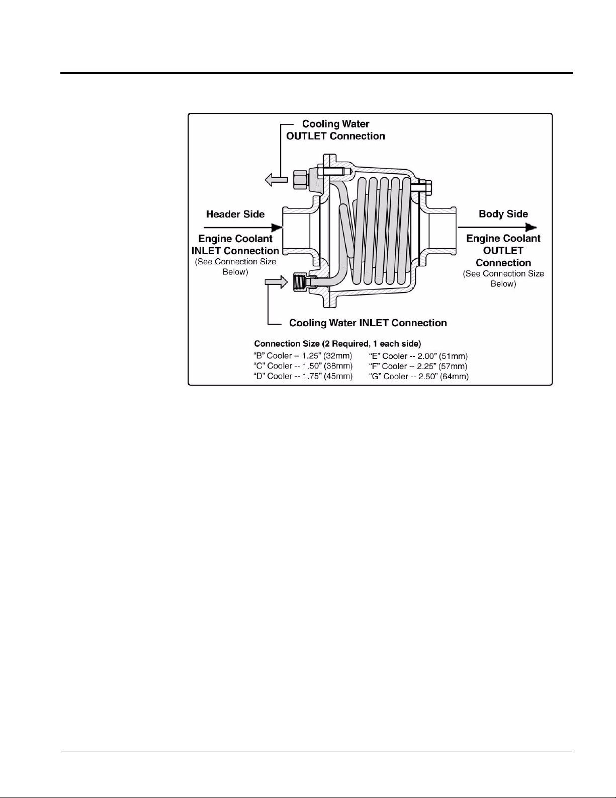
Accessories / Options
Figure 3-12: 2HP Booster Pump Option
Figure 3-1 1: Model “K” Heat Exchanger
Booster Pump Option, 2HP
Hale 2HP Booster Pumps offer low volume and high pressure for use with the
midship pumps. The booster is ideal for
high pressure, hose real operation and is
designed for direct mounting at the accessory port of the Hale “L” and “X” Series
gearboxes.
The pump is driven by the gearbox intermediate gear to provide a positive drive.
Water is directed to the booster pump
through a pre-piped supply hose.
In-Line / Discharge Valves
In-Line / discharge valves (Torrent SVS
V a lves) regulate the amount of water flowing through and leaving a pump. Each valve
includes a locking device to permits opera-
MUSCLE (Midship) Pumps Installation, Operation, and Maintenance Manual
p/n: 029-0020-63-0
45
Page 46

Accessories / Options
tion in any position from fully opened to fully closed. Also see Section 3.6 “Torrent SVS
V alves” on page 44.
Each discharge valve may be equipped with a drain. Opening the drain before uncoupling the hose relieves the pressure in the line and drains remaining water from the
pump during freezing conditions.
Drain Valves
V arious types and styles of manual and automatic drain v alves are a vailab le, with both
single and multiple ports opening.
The screw knob valve (MMD6) can connect up to six individual drain lines. The
MMD12 can connect to 12 individual drain lines. Each connection is individual. The
control knob is located on the operator’s panel. Turning the knob counterclockwise
OPENS the drain valve.
Suction Valves
Hale has valves that mount in the suction of the midship pump.
The Hale Master Intake Valve (MIV) becomes an integral part of the fire pump. When
the valve is ordered as part of a Hale Midship fire pump, the pump will pass UL
requirements up to 1,500 GPM (5,678 LPM) from the draft through a single 6” NST
suction hose with the valve in place. When two valves are mounted to the fire pump,
the pump can achieve NFPA Performance Point flows of 2,000 GPM (7,580 LPM)
from draft with dual 6” NST suction hoses. NFPA Performance Point flows of
2,250 GPM (8,516 LPM) is achieved with two MIVs and three 6” NST suction hoses.
The Hale MIV meets NFPA requirements for operations using a large diameter supply
hose. (See Figure 3-13: “Master Intak e Valve (MIV),” on page 47.) Further information
on the MIV can be found in manual P/N 029-0020-35-0.
46
MUSCLE (Midship) Pumps Installation, Operation, and Maintenance Manual
p/n: 029-0020-63-0
Page 47

Accessories / Options
Figure 3-13: Master Intake Valve (MIV)
Additional information on the MIV can be found in manual P/N 029-0020-35-0, supplied with the unit.
Tank Suction Valves
Hale offers the Torrent SVS Valve . Also see Section 3.6 “Torrent SVS Valves” on page
44.
Total Pressure Master (TPM) Relief Valve System
The Hale TPM system is a mechanical system, consisting of an internal relief valve
(QG) which by-passes water to the suction side of the pump; an e xternal relief (dump)
valve (PG30, with sensing v alv e attached), to discharge w ater to the atmosphere; and
a single panel mounted control valve (PMD), to provide control of pump pressure,
within NFPA required limits.
MUSCLE (Midship) Pumps Installation, Operation, and Maintenance Manual
p/n: 029-0020-63-0
47
Page 48

Accessories / Options
Figure 3-14: Hale (TPM) Total Pressure Master Relief Valve System
The TPM relief valv e system automatically relieves excess pump pressure when operating from draft or positive incoming flows. The system self-restores to the non-relieving position when excessive pressure is no longer present. The PMD control permits
the pump operator to “set” a desired pressure for both internal and external relief
valves. The panel control has an easy-to-read and easy-to-set adjustment with an
approximate pressure setting indication.
How the TPM Works
The TPM system monitors and controls pump pressure and relieves excessive pressure by first utilizing the internal relief valv e (QG), thus returning flow to the pump suction.
If excessive pressure remains and there is positiv e pressure on the suction, a secondary external relief valve (PG30) responds by discharging excessive pressure to the
atmosphere.
The staging of the internal and external relief valv es to operate in se ries ensures maximum protection against over pressure and eliminates the indiscriminate discharging
of water to the ground.
48
The external relief valve (PG30) is mounted on the discharge side of the pump. Discharged water flowing through the valve provides a self-cleaning process and nearly
MUSCLE (Midship) Pumps Installation, Operation, and Maintenance Manual
p/n: 029-0020-63-0
Page 49

Accessories / Options
eliminates the possibility of the valv e remaining in an ope n positio n due to contamination.
The amber indicator on the PMD control illuminates when the QG relief v alve is open.
The indicator flashes when both the QG and PG30 valves are open.
For sample TPM system overviews, see the following:
Figure 3-15: “Typical TPM Relief Valve System, Condition 1” on page 50
All Relief Valve CLOSED, Pump operating from Draft
Figure 3-16: “Typical TPM Relief Valve System, Condition 2” on page 51
QG Relief Valve OPEN, Pump operating from Draft
Figure 3-17: “Typical TPM Relief Valve System, Condition 3” on page 52
QG and PG30 Relief V alv e OPEN, Pump oper ating with P ositiv e Suction Pressure
(Hydrant)
MUSCLE (Midship) Pumps Installation, Operation, and Maintenance Manual
p/n: 029-0020-63-0
49
Page 50

Accessories / Options
50
Figure 3-15: Typical TPM Relief Valve System, Condition 1
MUSCLE (Midship) Pumps Installation, Operation, and Maintenance Manual
p/n: 029-0020-63-0
Page 51

Accessories / Options
Figure 3-16: Typical TPM Relief Valve System, Condition 2
MUSCLE (Midship) Pumps Installation, Operation, and Maintenance Manual
p/n: 029-0020-63-0
51
Page 52

Accessories / Options
52
Figure 3-17: Typical TPM Relief Valve System, Condition 3
MUSCLE (Midship) Pumps Installation, Operation, and Maintenance Manual
p/n: 029-0020-63-0
Page 53

4 Basic Operation
W ARNING!
THE PROCEDURES IN THIS SECTION ARE GENERAL OPERA TING PROCEDURES. NOT
ALL PROCEDURES IN THIS SECTION MAY APPLY TO YOUR SPECIFIC OPERATIONAL
REQUIREMENTS. REFER TO ONLY THOSE SECTIONS WHICH APPLY TO YOUR OPERATIONAL REQUIREMENTS.
THESE PROCEDURES DO NOT REPLACE THE PROCEDURES, POLICIES OR GUIDELINES ESTABLISHED BY THE AUTHORITY HAVING JURISDICTION, NOR DO THEY
REPLACE THE RECOMMENDATIONS AND PROCEDURES PROVIDED IN THE APPARATUS MANUFACTURER'S MANUAL.
ALWAYS REFER TO THE PROCEDURES PROVIDED BY THE AUTHORITY HAVING
JURISDICTION FOR OPERATING PROCEDURES, SETTING WHEEL CHOCKS, AS WELL
AS LA YOUT AND CONNECTION OF HOSES, VALVES AND DRAIN COCKS. ALL VALVES,
DRAIN COCKS AND CAPS SHOULD BE CLOSED.
Basic Operation
NEVER ATTEMPT TO SHIFT THE PUMP TRANSMISSION WHILE THE TRUCK TRANSMISSION IS IN GEAR. ALWAYS SWITCH THE TRANSMISSION TO NEUTRAL (N) AND
VERIFY THE SPEEDOMETER IS AT ZERO (0) BEFORE MAKING A PUMP TRANSMISSION SHIFT.
4.1 OVERVIEW
The instructions provided are for “split-shaft” and “PTO” pump applications:
Fluids - on page 54.
Pumping from a hydrant - on page 54.
Pumping from draft - on page 58.
Pumping from an onboard tank (Split-Shaft PTO) - on page 60.
Pumping in relay - on page 62.
Tandem (series) pumping - on page 64.
Pump and Roll - on page 65.
Post-operation procedures - on page 69.
Note: Also refer to NFPA 1901 Regulations for additional information for apparatus splitshaft and PTO requirements.
MUSCLE (Midship) Pumps Installation, Operation, and Maintenance Manual
p/n: 029-0020-63-0
53
Page 54

Basic Operation
IMPORTANT!
4.2 FLUID LEVELS
To meet various shipping regulations, ALL fluids within the pump and gearbo x assembly are drained prior to shipping from the factory.
AT INSTALLATION AND BEFORE OPERATING FOR THE FIRST TIME, OIL MUST BE
ADDED TO THE GEARBOX TO THE APPROPRIATE LEVEL. FOR THE PROPER OIL TO
USE AND QUANTITY REQUIRED, SEE SECTION 4, HEADING “GEARBOX LUBRICATION” ON PAGE 76.
4.3 STATIONARY PUMPING OPERATIONS
Pumping From a Hydrant, General Operation
1. Position the apparatus for the best hydrant hookup and discharge hose layout.
2. Bring the truck to a complete stop, apply the truck parking brake, then shift the
truck transmission to the NEUTRAL position. See WARNING! note on page 53.
3. Make sure the truck is at a complete stop before you attempt to shift from ROAD
to PUMP. Also see heading “Pump-To-Road Shift Procedures” on page 65.
For PTO operation (Qmax-U, Qtwo-U, and Qpak-J pumps), engage the PTO
(power take-off) per the PTO manufacturer’s instructions (move the in-cab pump
shift control valve to the PUMP position). The GREEN shift warning lights illuminate, indicating a complete shift. (See Figure 4-1: “Driver’s Compartment Indicator Lights” on page 55.)
For “Split-Shaft” operation, move the in-cab shift control from ROAD to PUMP
Position. The Green PUMP ENGAGED indicator light on the panel control will
light.
Place the truck transmission in the proper pump operating range or gear. For
most pumpers, this is direct drive (1:1) ratio. In addition, the speedometer
should register after the shift has been completed.
If the shift does not complete, then shift the transmission back to NEUTRAL
(N) and repeat the entire procedure.
Some vehicles drive the speedometer from the front wheel of the chassis. In
this case, the speedometer will not register after shifting to the PUMP position. See the chassis manual for details.
54
Note: If the truck manuf acturer has used another in -cab valv e to achie v e pump shift or of fers
an electric switch, follow the instructions supplied with that valve.
MUSCLE (Midship) Pumps Installation, Operation, and Maintenance Manual
p/n: 029-0020-63-0
Page 55

Basic Operation
CAUTION!
CAUTION!
4. Exit the driving compartment only after all the preceding steps are completed and
you are sure the appropriate lights in the cab and panel are ON.
DO NOT LEAVE THE CAB OR ATTEMPT TO PUMP UNTIL ALL GREEN PUMP LIGHTS IN
THE CAB ARE ON.
Figure 4-1: Driver’s Compartment Indicator Lights
DO NOT OPEN THE THROTTLE UNLESS THE GREEN INDICATOR LIGHT IS ON. (SEE
FIGURE 4-2: “PUMP OPERATOR’S P ANEL” ON PAGE 56.)
5. Verify that the pump panel GREEN shift indicator OK TO PUMP light illuminates
and that all hose connections are complete.
For “Split-Shaft” operation
Place the truck transmission in the proper pump operating range or gear. For
most pumpers this is direct drive (1:1) ratio. In addition, the speedometer
should register after the shift has been completed.
If the shift does not complete, shift the transmission back to NEUTRAL (N)
and repeat the entire procedure.
MUSCLE (Midship) Pumps Installation, Operation, and Maintenance Manual
p/n: 029-0020-63-0
55
Page 56

Basic Operation
CAUTION!
6. Open the hydrant. Bleed off the air from the suction hose.
7. Open the suction valve to allow water flow into the pump.
8. Open the appropriate valve to expel air or prime the pump, if so equipped. Also
Some vehicles drive the speedometer from the front wheel of the chassis.
In this case, the speedometer will not register after shifting to the PUMP position. See the chassis manual for details.
see heading “Pumping From Draft” on page 58.
Figure 4-2: Pump Operator’s Panel
9. Note the discharge and intake pressures, then gradually open the engine throttle
until the master discharge gauge indicates the desired pressure.
10. Set the automatic relief valve according to your fire department policy, if so
equipped. If your fire department does not have a policy, see heading “TPM
Operation from a Hydrant” on page 57.
DO NOT REDUCE THE PRESSURE ON THE INTAKE GAUGE BELOW DEPARTMENT
LIMITS. SERIOUS DAMAGE TO THE WATER MAIN COULD RESULT.
11. If the master intake gauge shows a vacuum before the desired discharge pressure or flow is achieved, you are receiving all the water that the suction piping
(hydrant) can supply.
56
MUSCLE (Midship) Pumps Installation, Operation, and Maintenance Manual
p/n: 029-0020-63-0
Page 57

Basic Operation
IMPORTANT!
12. If you need to increase pressure when this occurs, pump flow m ust be reduced or
the water supply improved.
To increase pressure, reduce the pump flow. However, the master intake gauge
reading must be maintained at 5 PSI (34 kPa), minimum.
13. As the throttle (engine speed) is increased, the pressure gauge reading
increases.
14. Close the throttle slowly until the pressure begins to stabilize and track with
engine speed. If this does not correct the problem, you may be pumping more
capacity than is available from the supply. Also check the inlet strainers for possible blockage.
15. Open the discharge valves.
IF THE PUMP OVERHEATS AND IS NOT EQUIPPED WITH THE HALE TRV, OPEN THE
VALVE TO ACCESS THE PUMP AUXILIARY COOLING SYSTEM, OR SLIGHTLY OPEN
THE TANK FILL LINE TO CIRCULATE WATER.
16. When pumping operations are completed, gradually reduce the pump pressure
until the engine returns to IDLE speed. See heading “Pumping From Draft” on
page 58. Disengage the PTO per the PTO manufacturer’s instructions. Also see
heading “Pump-To-Road Shift Procedures” on page 65.
TPM Operation from a Hydrant
When operating from a positive inlet pressure , it ma y be necessary to adjust the TPM
relief valve to a point where water is dumping to the ground.
The internal relief valve is always opened first, and if it cannot handle the pressure
rise, the external relief valve dumps water on the ground. When the internal relief
valve opens , the panel light illuminates , and when the external dump v alv e opens , the
light on the panel FLASHES.
Draft Limiting Factors
The effect of raised water temperatures when pumping from a positive pressure
source (i.e., a hydrant) is negligible on fire pump performance. However, when pumping from draft (static source such as a pond, lake or basin), elevated water temperature does have a limiting effect.
Water temperatures abo v e 95°F (35°C) cause a noticeab le decrease in lift when drafting. Also see Table G-2: “Lift Loss from Temperature” on page 195.
MUSCLE (Midship) Pumps Installation, Operation, and Maintenance Manual
p/n: 029-0020-63-0
57
Page 58

Basic Operation
CAUTION!
Barometric pressures below 29” Hg. can also limit lift when drafting. High elevations
and storm conditions can affect maximum flow available from any pump. Also see
Table G-3: “Lift Loss from Barometric Reading” on page 196.
Pumping From Draft
1. Position the apparatus as close to the water source as practical. The pump can
2. As the vertical lift increases to above 10 ft (3 m), pump capacity is reduced. Also
3. Bring the truck to a complete stop, apply the truck parking brake, shift the truck
4. Make sure the truck is at a complete stop before you attempt to shift from ROAD
draw 100% of its rated capacity with a 10 ft (3 m) vertical lift and 20 feet (6
meters) of suction hose.
see Table G-1: “Lift Loss from Elevation” on page 195.
transmission to the NEUTRAL position. See WARNING! note on page 53.
to PUMP. Also see heading “Pump-To-Road Shift Procedures” on page 65.
5. Engage the PTO (power take-off) per the PTO manufacturer’ s instructions (mo ve
the in-cab pump shift control valve to the PUMP position). The GREEN shift
warning lights illuminate, indicating a complete shift. (See Figure 4-1: “Driver’s
Compartment Indicator Lights” on page 55.)
Note: If the truck manufacturer uses another in-cab valve to achieve pump shift or offers an
electric switch, follow the instructions supplied with that valve.
DO NOT LEAVE THE CAB OR ATTEMPT TO PUMP UNTIL ALL THE GREEN PUMP
LIGHTS IN THE CAB ARE ON.
DO NOT OPEN THE THROTTLE UNLESS THE GREEN INDICATOR LIGHT IS ON. (SEE
FIGURE 4-2: “PUMP OPERATOR’S PANEL” ON PAGE 56.)
6. Exit the driving compartment only after all the above steps are completed and
you are sure that the appropriate lights in the cab and panel are ON.
7. Verify that the pump panel GREEN shift indicator OK TO PUMP light illuminates
and that all hose connections are complete.
For “Split-Shaft” operation
58
Place the truck transmission in the proper pump operating range or gear. For
most pumpers this is direct drive (1:1) ratio. The speedometer should register
after the shift has been completed.
If the shift does not complete, shift the transmission back to NEUTRAL (N)
and repeat the entire procedure.
MUSCLE (Midship) Pumps Installation, Operation, and Maintenance Manual
p/n: 029-0020-63-0
Page 59

Basic Operation
CAUTION!
CAUTION!
Some vehicles drive the speedometer from the front wheel of the chassis.
In this case, the speedometer will not register after shifting to the pump position. See the chassis manual for details.
8. Activate the priming pump - pull the control handle, or press the push button.
9. Your departmental manual for pumping should specify the correct RPM for priming. However, in general, priming should be operated at IDLE.
10. Running the engine at speeds higher than 1,200 RPM during priming is not recommended. It does not improve the priming operation but can cause damage to
the pump.
IF THE DISCHARGE GAUGE READING DOES NOT INCREASE, THE INTAKE GAUGE
READING DOES NOT FALL BELOW ZERO (0), OR THE PRIMING PUMP DOES NOT DISCHARGE WATER TO THE GROUND WITHIN 30 TO 45 SECONDS, DO NOT CONTINUE T O
RUN THE PRIMING PUMP.
STOP THE PUMP AND CHECK FOR AIR LEAKS OR POSSIBLE PROBLEMS. SEE SECTION 6 “TROUBLESHOOTING,” ON PAGE 93.
11. Monitor the intake and discharge master gauges. When the pump is primed, the
intake reading f alls belo w z ero (0), and the d ischarge pressure starts to increase.
You may also hear water splashing on the ground, indicating the pump is primed.
12. Gradually open the discharge v alv e until water e merges in a steady stream. Then
open the other discharge valves to the desired setting.
13. Gradually open the engine throttle until the desired pressure or flow is achieved.
DO NOT CA USE A WHIRLPOOL AT THE STRAINER. THIS ALLOWS AIR INTO THE PUMP,
CAUSING ROUGH OPERATION AND PULSATION. REPOSITION THE STRAINER OR
REDUCE FLOW.
14. As the throttle is opened, the pressure gauge reading increases with the engine
speed. If the engine speed increases without an increase in pressure, the pump
may be cavitating.
15. If the pump is cavitating, warn personnel that the flow is being REDUCED. Close
the throttle slowly until you operate without cavitation.
The following can also lead to cavitation:
Large nozzle tips - Use a smaller nozzle to reduce flow.
MUSCLE (Midship) Pumps Installation, Operation, and Maintenance Manual
p/n: 029-0020-63-0
59
Page 60

Basic Operation
16. If a pump shutdown is desired while pumping from draft, reduce the engine speed
17. To resume pumping, open the throttle and discharge valves. If the pump over-
Air enters with the water - Air leaks can cause rough operation and an
increase in engine speed without an increase in pressure or flo w . If an air leak
is suspected, discontinue pumping. See heading “Troubleshooting” on page
93.
Hot water - See heading “Lift Loss from Temperature” on page 195.
Low barometer - See heading “Lift Loss from Barometric Reading” on page
196.
High lift - see Table G-1: “Lift Loss from Elevation” on page 195.
Note: Also see Section Appendix G: “Cavitation” on page 193.
to IDLE and close the discharge valves.
heats from continued churning without water flow, open the discharge valves periodically to release hot water.
18. Set the automatic relief valv e according to your fire department policy. If your fire
department does not have a policy, see heading “TPM Operation from a Hydrant”
on page 57.
19. To avoid pump overheating, if not equipped with the Hale TRV valve, open the
pump auxiliary cooling system valve, or slightly open the tank fill line.
20. After completion of pumping procedures, gradually reduce the engine RPM to
IDLE speed. See heading “Pump-To-Road Shift Procedures” on page 65. Disengage the PTO per the PTO manufacturer’s instructions. Also see heading “Post
Operation Procedures” on page 69.
Pumping from On Board Water Tank (Split-Shaft PTO)
1. Position the truck for the best hydrant hookup and discharge hose layout.
2. Bring the truck to a complete stop, apply the truck parking brake, shift the truck
transmission to the NEUTRAL position. See WARNING! note on page 53.
3. Make sure the truck is at a complete stop before you attempt to shift from ROAD
to PUMP.
4. Move the in-cab pump shift control valve to the PUMP po sition. The shift w arning
lights illuminate, indicating a complete shift. (See Figure 4-1: “Driver’s Compartment Indicator Lights” on page 55.)
60
Note: If the truck manuf acturer has used another in -cab valv e to achie v e pump shift or of fers
an electric switch, follow the instructions supplied with that valve.
5. Exit the driving compartment only after all the above steps are completed and
you are sure that the shift completed lights in the cab and panel are ON.
MUSCLE (Midship) Pumps Installation, Operation, and Maintenance Manual
p/n: 029-0020-63-0
Page 61

Basic Operation
CAUTION!
CAUTION!
W ARNING!
6. Verify that the pump panel shift indicator OK TO PUMP green light is ON and that
all hose connections are complete.
DO NOT LEAVE THE CAB OR ATTEMPT TO PUMP UNTIL ALL THE GREEN PUMP
LIGHTS IN THE CAB AND PANEL ARE ON.
DO NOT OPEN THROTTLE UNLESS ALL GREEN PUMP INDICATOR LIGHTS ARE ON.
(SEE FIGURE 4-2: “PUMP OPERATOR’S PANEL” ON PAGE 56.)
7. Open the tank suction valve.
8. Check the master discharge gauge to see if priming is necessary. Start the priming pump - pull the control handle or press the prime push button.
IF DISCHARGE GAUGE READING DOES NOT INCREASE, THE INTAKE GAUGE READING DOES NOT FALL BELOW ZERO, OR THE PRIMING PUMP DOES NOT DISCHARGE
WATER TO THE GROUND WITHIN 30 TO 45 SECONDS, DO NOT CONTINUE TO RUN
THE PRIMING PUMP.
STOP THE PUMP AND CHECK FOR AIR LEAKS OR POSSIBLE PROBLEMS. SEE SECTION 6 “TROUBLESHOOTING,” ON PAGE 93.
9. Gradually open the engine throttle until the desired pressure or flow is achieved.
10. As the throttle is opened, the pressure gauge reading increases with the engine
speed. If the engine speed increases without an increase in pressure, the pump
may be cavitating. Also see Section Appendix G: “Cavitation” on page 193.
11. If the pump is cavitating, warn personnel.
DO NOT OPEN THROTTLE UNTIL ALL GREEN PUMP LIGHTS ARE ON. (SEE FIGURE 42: “PUMP OPERATOR’S PANEL” ON PAGE 56.)
12. Gradually open the discharge valve until the water emerges as a steady stream.
Then open the other discharge valves to the desired setting.
13. Set the automatic relief valv e or gov ernor according to your fire department policy
(or the separate governor manual).
MUSCLE (Midship) Pumps Installation, Operation, and Maintenance Manual
p/n: 029-0020-63-0
61
Page 62

Basic Operation
14. To avoid pump overheating, if not equipped with the Hale TRV valve, open the
15. After completion of pumping procedures, gradually reduce the engine RPM until it
4.4 PUMPING IN RELAY
Relay pumping is the movement of water through a number of consecutive pumpers,
from suction to discharge. Relay operations are necessary when the water source is
too far away from the fire to be pumped efficiently by one pumper. The number of
pumpers is determined by how far the water source is from the fire.
If your fire department does not have a policy, see heading “TPM Operation from
a Hydrant” on page 57.
pump auxiliary cooling system valve, or slightly open the tank fill line.
is at an IDLE speed. See heading “Pump-To-Road Shift Procedures” on page 65.
Disengage the PTO per the PTO manufacturer’s instructions. Also see heading
“Post Operation Procedures” on page 69.
In some cases, when you are on the receiving end of a relay, it may help to set the
suction dump or TPM (if available) very low. This limits the incoming pump pressure
by dumping water on the ground before the discharge hose lines are connected and
are flowing water.
Then, as the incoming water is used the relief valve control can be increased to the
desired operating pressure. This technique also helps to purge air from the incoming
hose and the pump before it gets to a dangerously high pressure.
Use this procedure after the hose is positioned, the apparatus are in position, and the
pumps are engaged. For setup and engagement instructions for apparatus receiving
pressurized water, see heading “Pumping From a Hydrant, General Operation” on
page 54.
Relay Procedures
Note: When feeding throug h a pump, the pump must be in pump gear and the transmission
in neutral in order to lubricate the pump and the intermediate gears.
1. Open two discharge gates on all pumps, except on the pump at the source, to
expel air from the hose lines and pumps.
2. On each pump , attach the hose lines to one of the discharges and leav e the other
discharge uncapped.
62
Note: Uncapping the second discharge gate is not necessary if a relay valve is installed.
The valve, connected to the intake side of the pump, automatically opens and dumps water
on the ground if too high a pressure is supplied, protecting the pump.
MUSCLE (Midship) Pumps Installation, Operation, and Maintenance Manual
p/n: 029-0020-63-0
Page 63

Basic Operation
IMPORTANT!
IMPORTANT!
Note: If no valve is pr esent, you must watch the intake gauge for a high-pressure reading. If
necessary, open the gate controlling the uncapped discharge to dump excess water on the
ground and reduce pressure.
3. Supply the pump at the water source with water; prime if necessary.
4. The discharge pressure must not exceed 185 PSI (1,276 kPa) for 5” (125 mm)
large diameter hose, or 135 PSI (931 kPa) for 6” (150 mm) hose, per NFPA Standards 1962. See heading “Pumping F rom a Hydrant, General Oper ation” on page
54. Also see heading “Pumping From Draft” on page 58.
FOR ADDITIONAL SUPPLY HOSE AND PRESSURE SETTING INFORMATION, SEE NFPA
STANDARDS 1962.
5. When the water reaches the second pump, close the uncapped discharge gate.
Repeat this step for all pumps until the water reaches the fire ground.
6. Adjust the throttle on the pump at the water source for the required operating
pressure. Watch the gauges to avoid cavitation.
page 193.
Also see heading “Cavitation” on
7. The pump operator at the fire scene must advise all other pump operators of the
amount of water needed at the fire ground.
8. Adjust the discharge pressure or flow at the fire scene to supply the lines being
used.
9. Observe the gauges carefully, and adjust the pressure or flow as needed.
10. Shutdown starts from the fire ground pump and works toward the water source.
Gradually reduce pressure at the fire ground pump until you can disengage the
pump.
11. Follow this procedure for every pump in the relay until the pump at the water
source is shut down.
LOCAL TRAINING PROCEDURES MAY VARY SLIGHTLY FROM ABOVE. ALWAYS FOLLOW LOCAL TRAINING PROCEDURES.
MUSCLE (Midship) Pumps Installation, Operation, and Maintenance Manual
p/n: 029-0020-63-0
63
Page 64

Basic Operation
CAUTION!
4.5 TANDEM (SERIES) PUMPING
Tandem pumping operations is used when higher pressures are required than a single engine is capable of supplying. This can occur when the pumper is attempting to
supply high-rise sprinkler or standpipe systems or long hose layouts.
WHEN SUPPLYING HOSE LINES IN A TANDEM PUMPING OPERATION IT IS POSSIBLE
TO SUPPLY GREATER PRESSURE THAN THE HOSE CAN WITHSTAND. PRESSURE
SUPPLIED TO THE HOSE SHOULD NOT EXCEED THE PRESSURE AT WHICH THE
HOSE IS ANNUALLY TESTED BY THE DEPARTMENT.
Note: Two 1,000 GPM (3,785 LPM) pumpers in a series from a hydrant can produce
500 GPM (1,893 LPM) at 500 PSI (3,447 kPa) if the relief valve systems allow 500 PSI
(3,447 kPa).
CONSULT NFPA 1962, “STANDARD FOR THE CARE, USE AND SERVICE TESTING OF
FIRE HOSE INCLUDING COUPLINGS AND NOZZLES,” FOR THE TEST PRESSURES
RECOMMENDED FOR THE TYPE OF FIRE HOSE USED BY YOUR FIRE DEPARTMENT.
In tandem pumping, the pumper directly attached to the water supply source pumps
water through its discharge outlet(s) into the intake(s) of the second engine. This
enables the second engine to discharge water at a much higher pressure than a single engine could have supplied. The h igher pressure results from the pumps acting in
series.
Tandem Procedures
1. Using the large intake hose, connect the first pumper to the hydrant steamer.
Open the hydrant until the pump is primed.
2. Position the second pumper “discharge-to-intake” with the first pumper.
3. Open a discharge to flow water.
4. Adjust the throttle on the first pumper until the intake gauge reads approximately
5 PSI (34 kPa).
5. Connect the second pumper to the unused streamer intake of the first pumper,
using a large intake hose (approximately 2-1/2” / 65 mm).
64
6. Both pumpers pump water to the fire. Also see heading “Pumping From a
Hydrant, General Operation” on page 54.
MUSCLE (Midship) Pumps Installation, Operation, and Maintenance Manual
p/n: 029-0020-63-0
Page 65

IMPORTANT!
LOCAL TRAINING PROCEDURES MAY VARY SLIGHTLY FROM ABOVE. ALWAYS FOL-
IMPORTANT!
IMPORTANT!
LOW LOCAL TRAINING PROCEDURES.
4.6 PUMP-TO-ROAD SHIFT PROCEDURES
(For Split-Shaft Gearboxes)
1. Verify that the operator’s hand throttle or governor control is at IDLE speed.
2. Shift the truck transmission into the NEUTRAL and wait about four (4) seconds.
Check to make sure the speedometer reads ZERO (0).
3. Set the pump to the ROAD position. The in-cab and panel pump indicator lights
go out as the pump transmission shifts into the ROAD position.
Basic Operation
REFER TO THE FIRE DEPARTMENT PROCEDURES FOR REMOVING WHEEL CHOCKS,
AS WELL AS LAY OUT AND CONNECTION OF SUCTION AND DISCHARGE HOSES.
4.7 PUMP AND ROLL
DURING PUMP AND ROLL OPERATION, IT IS NECESSARY TO SLOW THE FORWARD
MOTION OF THE APPARATUS TO THE PTO MANUFACTURER'S RECOMMENDED
ENGAGEMENT SPEED.
1. Slow the apparatus to a safe PTO engagement speed as recommended by the
PTO manufacturer’s recommendations.
Note: Most PTOs must be engaged while the apparatus is stopped. Only a “Hot Shift” PTO
can be engaged while the apparatus is rolling.
2. Engage the PTO.
3. Verify the PUMP ENGAGED light is ON. Also see Figure 4-1: “Driver’s Compartment Indicator Lights” on page 55.
4. Open the valve between the tank and pump suction.
5. Observe pump discharge pressure and verify that the pump pressure increases.
MUSCLE (Midship) Pumps Installation, Operation, and Maintenance Manual
p/n: 029-0020-63-0
65
Page 66

Basic Operation
6. Prime the pump, if necessary.
7. Open the discharge valves and commence operations.
4.8 RELIEF VALVE PROCEDURES
Be sure to select the correct procedure based on ho w the truc k is equipped . (See Figure 4-3: “TPM / PMD Relief Valve Control” on page 67.) Some trucks may utilize a
governor in place of the relief valve.
Standard Relief Valve Procedures
1. Increase the engine RPM to the desired pump operating pressure while reading
2. T urn the handwheel slowly countercloc kwise until the relief v alv e opens . The pilot
the discharge pressure gauge.
light illuminates and the master pressure gauge drops a few PSI (kPa).
3. T urn the handwheel slowly cloc kwise until the master pressure gauge rises to the
desired pressure and the pilot light goes out.
4. When the pump is not in operation, turn the handwheel clockwise to a position
slightly above the normal operating pressure. When the pump is put into operation again, reset the valve to the desired operating pressure. More complete and
detailed information is found in the relief valve manual.
TPM Relief Valve Procedures
1. Set the pressure indicator on the PMD control valve to a position slightly above
the normal operating pressure (even before water starts to flow).
2. When normal operating pressure is achieved (as indicated on the master pressure gauge while the pump is discharging water), slowly move the adjusting
handwheel counterclockwise until the relief valve opens.
66
MUSCLE (Midship) Pumps Installation, Operation, and Maintenance Manual
p/n: 029-0020-63-0
Page 67

3. The AMBER indicator light illuminates. (See Figure
CAUTION!
CAUTION!
Figure 4-3: TPM / PMD
Relief Valve Control
4-3: “TPM / PMD Relief Valve Control.”)
4. Turn the handwheel slowly clockwise until the light
goes out.
5. When the pump is not in operation, turn the handwheel clockwise to a position slightly above the normal operating pressure. More complete and detailed
information is found in the relief valve manual.
Basic Operation
THE PRESSURE INDICATOR ON THE PANEL IS ONLY A ROUGH INDICATION OF TPM
SETTING. ALWAYS USE THE PRECEDING PROCEDURE TO PROPERLY SET THE TPM
RELIEF VA LVE SYSTEM.
TPM System with Engine Governor
1. Set the pressure indicator on the PMD control valve to a position slightly above
the normal operating pressure (even before water starts to flow).
2. Power on the governor control per the manufacturer’s manual.
3. Set the discharge pressure using the RPM mode of the pressure governor control.
4. Move the TPM handwheel counterclockwise until the relief valve opens and the
AMBER pilot light illuminates.
5. Turn the handwheel slowly clockwise until the AMBER light just goes out. Then
turn the handwheel one additional full turn clockwise.
MUSCLE (Midship) Pumps Installation, Operation, and Maintenance Manual
p/n: 029-0020-63-0
THE TPM PRESSURE CONTROL VALVE MUST BE SET SLIGHTLY HIGHER THAN THE
GOVERNOR CONTROL FOR PROPER OPERATION.
67
Page 68

Basic Operation
CAUTION!
CAUTION!
6. Place the governor control in the PRESSURE GOVERNOR mode.
7. Use the following procedures to change the set pressure while running:
Increasing Pressure
Set the TPM to a pressure slightly higher than the desired new pressure.
Place the governor control in the RPM mode and increase the speed to the new
Turn the TPM handwheel counterclockwise until the relief valve opens and the
Turn the handwheel slowly clockwise until the AMBER light just goes out. Then
pressure.
AMBER pilot light illuminates. (See Figure 4-3: “TPM / PMD Relief Valve Control”
on page 67.)
turn the handwheel one additional full turn clockwise.
THE TPM PRESSURE CONTROL VALVE MUST BE SET SLIGHTLY HIGHER THAN THE
GOVERNOR CONTROL FOR PROPER OPERATION.
Place the governor control in the pressure governor mode.
Decreasing Pressure
Put the governor control in the RPM mode, and reduce the speed to the new pres-
sure.
Move the TPM handwheel counterclockwise until the relief valve opens and the
AMBER pilot light illuminates.
Turn the handwheel slowly clockwise until the AMBER light just goes out. Then
turn the handwheel one additional full turn clockwise.
THE TPM PRESSURE CONTROL VALVE MUST BE SET SLIGHTLY HIGHER THAN THE
GOVERNOR CONTROL FOR PROPER OPERATION.
Place the governor control in the PRESSURE GOVERNOR mode.
68
MUSCLE (Midship) Pumps Installation, Operation, and Maintenance Manual
p/n: 029-0020-63-0
Page 69

Basic Operation
W ARNING!
4.9 EMERGENCY PUMP SHIFT PROCEDURES
Before implementing manual o verride shift procedures , repeat the recommended shift
procedures. If the shift fails, proceed as follows:
1. Bring the truck to a complete stop.
2. Apply the truck parking brake, and chock the wheels.
3. Shift the truck transmission to the NEUTRAL.
4. For PUMP or ROAD position, place the in-cab shift control in the NEUTRAL (N)
position.
5. Shut down the engine.
DO NOT ATTEMPT EMERGENCY SHIFT PROCEDURES WHILE THE ENGINE IS RUNNING.
6. Employ manual override procedure at the shift cylinder on the pump gearbox as
follows:
An eyebolt is provided in the shift shaft to accept a drift punch or screwdriver.
Insert the tool into the hole provided, then pull or push the shaft manually.
Pull the shaft OUT for PUMP position (after in-cab control valve selection), or
push shaft IN for ROAD position (after in-cab control valve selection).
If the shift stroke cannot be completed manually, turn the driveshaft slightly by
hand to realign the internal gears and repeat the manual shift.
Note: Certain apparatus may offer a manual shift override handle or separate cable fo r activation.
7. Once gearbox shift is complete, make sure all personnel are clear of the underside of that apparatus and start the engine to proceed with the desired operation.
4.10 POST OPERATION PROCEDURES
1. Return the engine to IDLE, then slowly close all valves.
2. Place the transmission in NEUTRAL, then slowly shift to ROAD to disengage the
pump.
3. Drain the pump (especially important in freezing weather):
Open the discharge valves, remove suction tube caps, and discharge valve
caps.
MUSCLE (Midship) Pumps Installation, Operation, and Maintenance Manual
p/n: 029-0020-63-0
69
Page 70

Basic Operation
4. If sea water, dirty water, alkaline water or foam solution has been used, FLUSH
5. If installed, drain the gearbox cooler. After the pump is completely drained,
6. Remove the wheel chocks only when preparing to leave the scene.
7. Fill out the Pump Run Log, indicating total pumping and out-of-station time.
8. Report all pump, vehicle and equipment malfunctions, and irregularities to the
9. Know and follow all local procedures. See WARNING! note on page 53.
Open the pump body drain cocks or Hale multiple drain valve. If a multiple
drain valve is used, all pump drain lines should be connected to this valve.
On two-stage pumps, move the transfer valve back and fourth between the
VOLUME and PRESSURE positions.
THE PUMP WITH CLEAN WATER.
replace all caps and close all valves.
proper authority.
70
MUSCLE (Midship) Pumps Installation, Operation, and Maintenance Manual
p/n: 029-0020-63-0
Page 71

Truck Manufacturer ______________________________
Pump Model Number _____________________________
Pump Serial Number _____________________________
Year _____________Unit #________________________
Midship Pump Maintenance Check List
RECOMMENDED “WEEKLY” PROCEDURES
Test relief valve system or governor at 150, 200, 250 PSIG (1000, 1400, 1700
kPa) - see page 80.
Test transfer valve (if applicable) - see page 73.
Test the priming system. Flush the priming system - Also see Chapter 4, head-
ing “Weekly” on page 72.
Lubricate all valves, discharge, suction, hose, drain, and multi-drain - see page
74.
Check pump shift warning indicator lights - see page 74.
Recommended MONTHLY
Procedures
Complete weekly checks.
Lubricate threads on PM relief valve panel
control and check lights.
Lubricate remote valve controls.
Check controlled packing leakage and
adjust if necessary (8 to 10 drops per
minute).
Perform dry vacuum test.
Check drive flange bolts for tightness.
Lubricate suction tube threads.
Clean strainer.
Inspect gaskets.
Check oil level in pump gearbox; add oil if
necessary.
If necessary, replace oil.
a. *Per NFPA-1911, 22” Hg. minimum vacuum: loss not to exceed 10” Hg vacuum in five (5) minutes.
a
Jan Feb Mar Apr May Jun Jul Aug Sept Oct Nov Dec
MUSCLE (Midship) Pumps Installation, Operation, and Maintenance Manual
p/n: 029-0020-63-0
91
Page 72

RECOMMENDED “ANNUAL” PROCEDURES
Complete all previous checks on all questions.
Check gauge calibration - see page 75.
Check oil level in AutoLube® assembly (SAE-EP 90 or 80W-90); see operation
and maintenance manual for details.
Lubricate power transfer cylinder, power shift cylinder, and shift control valve
with vacuum cylinder oil, if applicable.
Change pump gearbox oil and refill (SAE-EP 90 oil or 80W-90).
Check individual drain lines from pump to multi-drain to ensure proper drainage
and protection from freezing.
Lubricate transfer valve mechanism on two stage pumps. Dry moly spray is pre-
ferred.
Disassemble priming pump and clean vanes.
Run yearly standard pump test (per NFPA-1911) to check pump performance
levels – chart provided below.
Repacking of pump is recommended every two or three years.
Note: The preceding general recommendations are provided for normal use and conditions. Extreme conditions or variables may indicate a need for increased maintenance.
Good preventative maintenance lengthens pump life, ensures greater dependability, and
minimizes downtime. See “Muscle Pump Service Chart, Part 1 of 3” on page 88.
Category
Hose Layout
Nozzle Size
Nozzle Pressure
Gallons (Liters) per Minute
Pump Pressure, Current Engine Speed
Engine Speed from Original Test
Documents
Lift and Suction Hose Size and
Number.
92
Annual pump Test Results, in PSIG (kPa)
Capacity at 150
(1000)
MUSCLE (Midship) Pumps Installation, Operation, and Maintenance Manual
Capacity at 200
(1400)
Capacity at 250
(1700)
p/n: 029-0020-63-0
Page 73

5 Preventive Maintenance
5.1 OVERVIEW
The following procedures are for normal use and conditions. Extreme conditions may
indicate a need for increased maintenance. The procedures in this section identify
some extreme conditions and the additional measures needed to ensure lengthened
pump life and continuing dependability. Always follow local maintenance and test procedures.
5.2 POST OPERATION
1. On two-stage pumps, remove the suction tube strainers and ensure that check
valves are fre e to s wing. Verify that no foreign matter is caught betwee n the v alv e
and the seat.
Preventive Maintenance
2. Inspect the suction hose rubber washers and washers in the suction tube caps.
Remove foreign matter from under these washers. Replace worn, damaged, or
dry washers.
3. Verify that all discharge valv es , booster line valves, drain valves , and valve cocks
are closed.
4. Tighten suction caps.
5. Make sure the gearbox oil reservoir is full to correct level - see heading “Replace
Gearbox Oil” on page 80. Also see Figure 5-5: “Muscle Pump Service Chart, Part
2 of 3” on page 89.
Note: The auto-lube assembly is NOT drained at shipment but must be checked prior to
operation. To check auto-lube oil, see Step 18. of Section 7.6 “QMID/QMAX/QTWO AutoLube ® Service” on page 116. Also see Figure 5-4: “Muscle Pump Service Chart, Part 1 of 3”
on page 88.
5.3 EXTREME CONDITIONS
Extreme conditions occur when operating in freezing weather or as a result of pumping from a water source that contains material that is harmful if not purged.
During Freezing Weather
In freezing weather, drain the pump as follows:
MUSCLE (Midship) Pumps Installation, Operation, and Maintenance Manual
p/n: 029-0020-63-0
71
Page 74

Preventive Maintenance
1. Open all discharge and suction valves, remove suction tube caps, and discharge
valve caps.
2. Open pump body drain cocks and/or Hale multiple drain valve.
3. On two-stage pumps, move the transfer valve back and forth between both the
VOLUME and PRESSURE positions.
4. After the pump is completely drained, replace all caps and close all valves.
Pumping Salt Water, Contaminated Water, or Foam Solution
1. Flush the pump and suction hoses using fresh, clean water.
2. After pumping foam, flush as above until all foam residue is flushed from the system.
3. Drain the gearbox cooler, if installed
5.4 WEEKLY
Weekly maintenance consists of the following:
Test the relief valve or governor system - see page 73
Test the priming system - see page 74.
Establish and HOLD prime control for about three (3) to five (5) seconds to flush
fresh water through the priming pump.
Note: DO NOT apply lubricant the primer pump vanes or vane slots. Lubricant and cold
water produces a gummy residue that renders the unit inoperative.
Test the transfer valve on two stage pumps - see page 73
Test the pump shift warning indicator lights - see page 74
Perform valve maintenance - see page 74
Check and clean the intake strainers - see page 75
Check any auxiliary engines - see page 75
Verify all gauges are in working order - see page 75
Operate pump controls - see page 75
If testing criteria is not met, refer to Section 6 “Troubleshooting” on page 93 f or corrective maintenance procedures.
72
MUSCLE (Midship) Pumps Installation, Operation, and Maintenance Manual
p/n: 029-0020-63-0
Page 75

Preventive Maintenance
Relief Valve and TPM Test
When the relief valve is not in operation, maintain a setting above the normal operating pressure. Also see Figure 4-3: “TPM / PMD Relief Valve Control” on page 67.
1. Open the discharge valve, back to the water tank, less than 1/2 way. Also see
Section 3.3 “Pressure and Relief Valve Control” on page 39.
2. Increase pump pressure up to 150 PSI (1034 kPa).
3. Turn the relief valve handwheel counterclockwise until the relief valve opens and
the AMBER light illuminates. The master pressure gauge should drop at least 5
to 10 PSI (35 to 69 kPa).
4. T urn the control valve handwheel clockwise then counterclockwise a few times to
ensure that the handwheel turns freely. Observe the master pressure gauge and
indicator light for proper valve operation.
5. Reset the relief valve to its normal operational setting.
Governor Test
If your apparatus is equipped with an electronic governor, follow the manufacturer’s
instructions for weekly preventive maintenance.
Transfer Valve Test (Two-Stage Pumps Only)
1. For MANUAL transfer valves:
With the engine turned OFF, turn the handwheel between VOLUME and
PRESSURE a few times to verify that the valve operates freely.
Set the truck for pumping with the transf er v alve set to V OLUME. See heading
“Relief Valve Procedures” on page 66. Also see heading “TPM Relief Valve
Procedures” on page 66.
With the engine at IDLE speed, sat the transfer valve to PRESSURE.
Verify that the discharge pressure gauge readings have approximately dou-
bled.
2. For POWER transfer valves:
With the engine turned OFF, use either a 3/8” socket on the indicator hex nut
or insert a rod in the hole in the indicator hex nut and manually transfer the
valve back-and-forth to verify that the valve operates freely.
Set the truck for pumping with the transf er v alv e set to V OLUME. Note the dis-
charge gauge readings.
MUSCLE (Midship) Pumps Installation, Operation, and Maintenance Manual
p/n: 029-0020-63-0
73
Page 76

Preventive Maintenance
CAUTION!
With the engine at IDLE speed, set the transfer valve to PRESSURE.
Verify that the master intake gauge readings have approximately doubled.
Priming System Test
1. Tighten all pump caps, and close all pump valves.
2. Pull the primer control while you w atch f or a below-z ero (0) reading on the master
intake gauge.
3. Continue operation for three (3) to five (5) seconds after the primer starts flushing
water through the pump to clear any possible dirt or slug (gum) buildup.
4. Verify that the master intake gauge readings hold for approximately five (5) minutes after you release the primer control. A drop of 10” Hg. in this 5 minute period
is anticipated per NFPA 1901.
5. If air leaks are heard or the gauge bounces back to or above zero (0), the pump
or valves require service.
Pump Shift Warning Lights
1. Switch to non-pumping operations and verify the warning indicators are OFF. See
Section 4 “Basic Operation” on page 53.
2. Verify that the warning indicators in the cab and on the pump control panel function properly.
MAKE SURE EVERYONE IS CLEAR OF THE APPARATUS BEFORE SHIFTING TO THE
PUMP POSITION. VERIFY THE PARKING BRAKE IS SET AND THE WHEELS ARE
CHOCKED TO PREVENT ANY MOVEMENT OF THE APPARATUS.
3. Repair or replace any malfunctioning indicators.
Valve Maintenance
Refer to the separate valve manual for proper valve maintenance procedures.
Lubricate all moving parts of the suction, discharge, hose drain, and multi-drain v alves
and valve linkage with a good grade of grease. For recommended grease, see “Lube
and Sealant Specifications” on page 187.
74
MUSCLE (Midship) Pumps Installation, Operation, and Maintenance Manual
p/n: 029-0020-63-0
Page 77

Preventive Maintenance
Note: The PMD valve should be lubricated every six (6) months.
Intake Strainers
Check and clean any debris from the intake.
Flush the pump, if required, using departmental/company procedures.
Repair or replace any damaged strainers.
Verify All Gauges are in Working Order
Any gauge that is repeated in the cab or another panel, must ag ree with the gauge on
the operator's panel. Gauges not reading within 10% of the calibr ated test gauge must
be removed from service and re-calibrated.
Operate Pump Controls
Operate the pump drive controls to verify the pump engages . Verify the indicator lights
work properly.
Inspect Water and Foam Tanks
Inspect water and foam tanks for proper level and gauge readings. If any debris is
present, flush the tanks to protect the pump from wear caused by dirty water or foam
concentrate.
Check Auxiliary Engine
See engine manufacturer’s manual for wear and proper operation.
5.5 MONTHLY
Monthly maintenance includes the weekly maintenance procedures plus:
Valve lubrication - see page 76
Suction Check Valve testing - see page 76
Gearbox lubrication - see page 76
Dry vacuum testing - see page 78
Checking the pump and drive line bolts - see page 77
MUSCLE (Midship) Pumps Installation, Operation, and Maintenance Manual
p/n: 029-0020-63-0
75
Page 78

Preventive Maintenance
Relief valve system check - see page 81
Valve Lubrication
1. On handwheel-type valves, including PM, PMD, and Transfer Valve Controls,
remove old grease and paint, use a dry lubricating spray on gears.
2. Lubricate suction threads with a light coat of grease.
Suction Check Valve Testing, Two-Stage Pumps
On two-stage pumps, remov e the suction tube strainers , and reach inside the pump to
ensure that the check valves are free to swing. Also verify that no foreign matter is
caught between the valve and the seat.
Gearbox Lubrication
Incorrect oil types or amounts of oil result in unnecessary high oil temperature and
possible wear or damage. Change the oil every 12 months, depending on pump
usage. All lubricants must meet service rating API GL-5 requirements. (See Figure 55: “Muscle Pump Service Chart, Part 2 of 3” on page 89.)
Note: For domestic use, Hale recommends using an SAE EP-90, 80W90 Lubricant or
“RoadRanger” Full Synthetic SAE 50 Transmission Lubricant, manufactured by the Eaton
Corporation, or equivalent. For International use, Hale recommends using an ISO68 lubricant, or equivalent.
®
1. For gearbox capacity - see heading “Lube and Sealant Specifications” on page
187.
2. Remove the gearbox oil fill plug, and check the le v el of the oil in the gearbo x. The
oil level should be up to the bottom of the oil fill plug hole. Also see Figure 5-5:
“Muscle Pump Service Chart, Part 2 of 3” on page 89.
3. Have clean disposable shop rags and oil dry handy and a suitable container to
collect the fluid.
4. If the oil appears white or “milky,” a water leak is indicated. Remove the drain plug
and drain the oil into a suitab le container. Examine the oil for metal flakes or other
contamination.
Note: If water leak / contamination is suspected, see Section 5 Troubleshooting, heading 6
“Troubleshooting” on page 93.
76
5. Either of these conditions indicates maintenance is required to the unit. See Section 9.1 “G Series Gearbox Maintenance” on page 149. Also see Section 9.2 “J
Series Gearbox Maintenance” on page 157.
MUSCLE (Midship) Pumps Installation, Operation, and Maintenance Manual
p/n: 029-0020-63-0
Page 79

Preventive Maintenance
W ARNING!
Packing Gland Adjustment
The packing gland is adjusted for a leakage rate of about 8 to 10 drops per minute at
150 PSI (1034 kPa). This slight leakage lubricates and cools the shaft and packing to
prevent burning and scoring.
Check the leakage rate, and adjust the packing gland if necessary. If the leakage rate
cannot be adjusted within satisfactory limits, replace packing. See Section 8.1 “Packing Seal Replacement” on page 131 for additional information.
Packing should be replaced every three (3) years.
Adjustment
1. Connect the pump to a fresh water source of about 150 PSI (1034 kPa). If this is
not possible, operate the pump at about 150 PSI from draft or from the booster
tank discharging through the booster line, another small nozzle, or circulating
back to the tank.
2. Count the drops (water leakage) per minute.
3. Shut down engine to make adjustments.
DO NOT RUN THE ENGINE WHILE MAKING PACKING ADJUSTMENTS.
4. Loosen the packing nut lock. The lock is either a spring-loaded pin. The end of
the lock fits into a slot in the gland. (See Figure 5-2: “Pump Packing Seal Assembly” on page 86.)
5. To loosen or tighten the packing gland:
Insert a screwdriver or rod into one of the slots. Refer to the Hale Service
Chart.
To loosen the nut, turn it in the direction of engine rotation.
To tighten the nut, turn it in the opposite direction to engine rotation.
6. Repeat Steps 1 through 3 and verify that leakage is correct. Tighten to REDUCE
leakage, loosen to INCREASE leakage.
Pump, Drive Line and Flange Bolts
Check all pump, drive line and flange bolts to ensure:
1. No bolts are missing.
MUSCLE (Midship) Pumps Installation, Operation, and Maintenance Manual
p/n: 029-0020-63-0
77
Page 80

Preventive Maintenance
Figure 5-1: Priming
Valve Handle
2. All bolts are tight. Use a torque wrench and torque bolts to the drive train manufacturer's recommended specifications.
3. Bolts used are “Grade 5” minimum for mounting and “Grade 8” minimum for the
driveline.
Priming System Test (Dry Vacuum Test)
(Refer to NFPA 1901 or NFPA 1911)
1. Close all valves and drains. Cap all suction openings and
the outlet of the suction side relief valv e (if so equipped).
2. Connect a test vacuum gauge or manometer to the
intake test gauge connection on the pump panel.
3. Engage the priming pump until the gauge indicates 22”
Hg.
4. Compare the readings of the test gauge and the apparatus gauge. Note any difference.
5. STOP the priming pump and observe the gauge. If the
vacuum falls more then 10” Hg. in five (5) minutes it is an indication of at least
one air leak.
6. Vacuum leaks may often be detected by ear if the engine is turned OFF. Correct
leaks immediately before returning the pump to service.
7. Test the suction hose as follows:
Attach the suction hose to the pump.
Place the suction tube cap on the end of the hose in place of a strainer.
Close all valves and drains. Cap all suction openings and the outlet of the
suction side relief valve (if so equipped).
Connect a test vacuum gauge or manometer to the intake test gauge connec-
tion on the pump panel.
Engage the priming pump until the gauge indicates at least 22” Hg.
If the vacuum falls more then 10” in 5 minutes, at least one air leak exists.
Verify the test gauge and the apparatus gauge display the same readings.
Repair or replace and gauges that do not display the correct pressure.
78
MUSCLE (Midship) Pumps Installation, Operation, and Maintenance Manual
p/n: 029-0020-63-0
Page 81

IMPORTANT!
IF LEAKS CANNOT BE DETECTED BY FOLLOWING THE PROCEDURE, IT IS ADVIS-
IMPORTANT!
ABLE TO TEST THE PUMP HYDROSTATICALLY.
TO TEST:
OPEN ALL VALVES
PLACE CAPS ON ALL VALVES
CONNECT A POSITIVE PRESSURE SOURCE (TYPICALLY 250 PSI / 17 BAR)
INSPECT THE PUMP FOR LEAKS
5.6 ANNUAL
Preventive Maintenance
Annual maintenance consists of post-operation, weekly, and monthly maintenance
plus the following tasks:
Replacing the pump gearbox oil - see page 80.
Relief valve system, check and repair - see page 80.
Checking individual drain lines from the pump to the multi-drain to ensure proper
drainage and protection from freezing - see page 81.
Disassembly of priming pump to clean vanes - see page 81. (Also see separate
manual provided.)
DO NO USE A LUBRICANT ON THE PUMP VANES AND VANE SLOTS. LUBRICANT AND
COLD WATER FORM AN EVENTUAL GUMMY RESIDUE THAT RENDERS THE PRIMING
SYSTEM INOPERATIVE. A COMPLETE AND THOROUGH DISASSEMBLY AND CLEANING IS THEN REQUIRED.
MIV Relief Valve Test and Adjustment - see page 81.
Relief Valve Test and Adjustment - see page 81.
Yearly pump test to check performance levels, including Tank-to-Pump Flow Rate
- see page 82. (Also see NFPA 1911 standard for more details.)
Repacking the pump seal at three-year intervals - see page 85
Autolube
®
assembly oil level check - fill or replace with SAE EP 90 or 80W90
weight oil.
MUSCLE (Midship) Pumps Installation, Operation, and Maintenance Manual
p/n: 029-0020-63-0
79
Page 82

Preventive Maintenance
Lubricating the power transf er cylinder, power shift cylinder , and shift control valve
with air cylinder oil.
Replace Gearbox Oil
1. Remove the drain plug (magnetic) and drain the gearbox oil into a suitable container. For container size based on gearbox capacity, see “Lube and Sealant
Specifications” on page 187. Also see Figure 5-5: “Muscle Pump Service Chart,
Part 2 of 3” on page 89.
2. Have clean disposable shop rags and oil dry handy.
Note: Assembly orientation determines which plugs are used for oil fill, drain and level
detection. See installation plate drawings located at the back of this manual.
3. Examine the oil for contamination (e.g., water – turns the oil a milky color or settles to the bottom). Also see Section 5 Troubleshooting, heading “Water/Moisture
in Pump Gearbox.” on page 101.
4. Properly dispose of the used oil.
5. Inspect the magnetic drain plug. If metal filings are present, visually inspect and
clean the internal components.
6. Clean the drain plug (magnetic).
7. Repair or replace gearbox components as necessary. See appropriate Section
for gearbox service.
8. Replace the cooler, if necessary.
9. Remove the oil fill plug and install the drain (magnetic) plug, using suitable thread
sealant.
10. Fill the gearbox with an appro v ed gear oil until oil just begins seeping from the oil
level plug opening. For gearbox capacity, see “Lube and Sealant Specifications”
on page 187. Also see Figure 5-5: “Muscle Pump Service Chart, Part 2 of 3” on
page 89.
11. Install the oil fill plug using suitable thread sealent.
Relief Valve System Check
1. Place apparatus out of service in accordance with departmental procedures.
80
2. Test relief valve system in accordance with weekly maintenance check. Also see
heading “Weekly” on page 72.
3. If the relief valve is not working, clean the strainers as follows:
Open pump compartment panel and locate the relief valve system stra iner(s).
MUSCLE (Midship) Pumps Installation, Operation, and Maintenance Manual
p/n: 029-0020-63-0
Page 83

Preventive Maintenance
IMPORTANT!
On all relief valve systems, the str ainer is located in one of the pump pressure
ports. On a TPM, an additional strainer is located in one of the pump vacuum
ports.
Note: An optional panel-mounted strainer is mounted on some apparatus .
Disconnect tubing then remove strainer from respective tap.
Clean any debris from strainer and check strainer for damage.
Using a suitable thread sealant (Loctite PST or equivalent) reinstall strainer.
Reconnect tubing.
4. Test apparatus and check for leaks around strainer fittings.
5. Place apparatus back in service.
Check Drain Lines to Multi-Drain
Drains are supplied on the pump and piping at the lowest points where water could
collect and freeze. Most drain lines are piped together to a multi-drain to allow the
entire system to be drained by one valve.
It is necessary to inspect each line of the multi-drain to ensure the entire system is
draining when the valv e is operated. Inspect each connection and v erify the individual
lines to the multi-drain are free of debris. Repair and/or replace any lines that are
damaged, kinked, or corroded.
Clean Priming Pump
Disassemble the priming pump and clean the housing and vanes. Inspect the vanes
for wear and replace as needed. Reassemb le the pump and test f or proper operatio n.
(See separate manual provided.)
DO NO USE A LUBRICANT ON THE PUMP VANES AND VANE SLOTS. LUBRICANT AND
COLD WATER FORM AN EVENTUAL GUMMY RESIDUE THAT RENDERS THE PRIMING
SYSTEM INOPERATIVE. A COMPLETE AND THOROUGH DISASSEMBLY AND CLEANING IS THEN REQUIRED.
MIV Relief Valve Test and Adjustment
See separate manual for additional information.
MUSCLE (Midship) Pumps Installation, Operation, and Maintenance Manual
p/n: 029-0020-63-0
81
Page 84

Preventive Maintenance
Performance Testing Overview
The yearly standard performance test consists of checking the pumper, (according to
rating) at three capacities and comparing the results to when the pump was first
placed in service. This provides some measure of performance deterioration, if any.
(See Table 5-1: “Pump Ratings (GPM / LPM)” on page 82.)
A pump must be able to pump FULL rated capacity at 150 PSI (1000 kPa), 70%
capacity at 200 PSI (1400 kPa) and 50% capacity at 250 PSI (1700 kPa).
Table 5-1: Pump Ratings (GPM / LPM)
Capacity
100% 150 (1000)
100% 165 (1100)
70% 200 (1400)
50% 250 (1700)
Pressure
PSI (kPa)
Pump Rating in GPM (LPM)
500
(2,000)
500
(2,000)
500
(2,000)
350
(1,400)
250
(1,000)
750
(3,000)
750
(3,000)
750
(3,000)
525
(2,100)
375
(1,500)
1,000
(4,000)
1,000
(4,000)
1,000
(4,000)
700
(2,800)
500
(2,000)
1,250
(5,000)
1,250
(5,000)
1,250
(5,000)
875
(3,500)
625
(2,500)
1,500
(6,000)
1,500
(6,000)
1,500
(6,000)
1,050
(4,200)
750
(3,000)
1,750
(7,000)
1,750
(7,000)
1,750
(7,000)
1,225
(4,900)
875
(3,500)
2,000
(8,000)
2,000
(8,000)
2,000
(8,000)
1,400
(5,600)
1,000
(4,000)
2,250
(9,000)
2,250
(9,000)
2,250
(9,000)
1,575
(6,300)
1,125
(4,500)
3,000
(12,000)
3,000
(12,000)
3,000
(12,000)
2,100
(8,400)
1,500
(6,000)
Tank-to-Pump Flow Rate Test
Note: This procedure is provided as a ref erence o nly. It does not supersede any local proce-
dures.
1. Fill the water tank until it overflows.
2. Close the tank fill line, bypass the cooling line, and all the pump intakes.
3. Attach sufficient hose lines and nozzles to pump the desired discharge rate.
4. With the pump in gear, open the discharge and begin pumping water.
82
5. Increase the engine throttle until the maximum consistent pressure is obtained on
the discharge gauge.
6. Close the discharge valve without changing the throttle setting. Refill the tank.
The bypass valve may be opened to prevent pump overheating.
7. Reopen the discharge valve and check the flow through the nozzle using a Pitot
tube or flow meter. Adjust the engine throttle to bring the pressure to the amount
previously determined.
8. Compare the flow rate measured to the NFPA minimum or the designated rate of
the pump. If the flow rate is lower, a problem may exist in the tank-to-pump line.
MUSCLE (Midship) Pumps Installation, Operation, and Maintenance Manual
p/n: 029-0020-63-0
Page 85

Preventive Maintenance
The minimum flow rate should be contin uously discharged until 80% of the tank is
discharged.
9. The pump should not experience mechanical problems, power loss, or overheat
during the test.
Performance Testing Equipment and Materials
Pumpers should be tested from draft at not over a 10’ (3 m) lift with 20’ (6 m) of suction hose. Pumpers rated at 1,500 GPM (6,000 LPM) and above often require two
separate 20-foot (6-meter) lengths of suction hose and a lower lift height.
Use smooth bore test nozzles of accurate size with the Pitot gauge. The volume
pumped is then determined by reference to discharge tab les f o r smooth nozzles . Preferably, nozzles will be used on a Siamese deluge gun for greatest accuracy. A stream
straightener, just upstream of the nozzle is advisable.
Refer to local procedures for pump testing procedures and practices as well as applicable nfpa standards.
For Pitot Gauge accuracy, the nozzle pressures should be between 30 and 85 PSIG
(207 and 586 kPa). Also see Appendix F: “Nozzle Size vs. Pressure” on page 191.
The amount of discharge hose required for the service tests is dependent on the flow
requirements and capacity test point. Provide adequate hose to discharge the rated
capacity with a flow velocity less that 35 ft./sec. Also see Appendix E: “Hose Friction
Loss” on page 189.
Since NFPA standards specify both GPM and pressure, it is usually necessary to
restrict the flow somewhat to build up the pump pressure. In normal pumping, this
restriction would be caused by the friction loss in the lines. It is common practice to
gate the discharge valves as required to maintain pressure.
Note:
For 750 GPM (3,000 LPM) test, two 2-1/2” (64 mm) lines should be laid from
the pumper to the nozzle
For 1,000 GPM (4,000 LPM) test, three lines are required
For the 1,250 GPM (5,000 LPM) and 1,500 GPM (6,000 LPM) tests, four or more
lines are required between the pumper and the nozzle.
For the 1,750 GPM (7,000 LPM), 2,000 GPM (8,000 LPM), and 2,250 GPM
tests up to six hose lines into two separate nozzles should be used. Also se e
Appendix F: “Nozzle Size vs. Pressure” on page 191.
Because deluge guns are not always available, other hose layouts may be used, such as
one, 2-1/2” (64 mm) line to a 1-3/8” (35 mm) nozzle fo r 500 GPM (1,8 92 LPM). Gener ally, the
MUSCLE (Midship) Pumps Installation, Operation, and Maintenance Manual
p/n: 029-0020-63-0
83
Page 86

Preventive Maintenance
nozzle used on one, 2-1/2” line should not be larger than 1-1/2” (38 mm) for accuracy in
measuring GPM (LPM).
Another alternative when a deluge gun is not available consists of a 1-1/4” (32 mm) nozzle
on one and a 1-1/2” (38 mm) nozzle on t he ot her t o pa ss 1 ,0 00 GPM ( 3, 785 LPM) . The su m
of the flow from both nozzles is the GPM (LPM) delivered by the pump. For good pitot gau ge
accuracy, the nozzle pressures should be between 30 and 85 PSIG (207 and 586 kPa).
Performance Testing
NFPA standards require a 10% reserve in pressure at the capacity run when the
apparatus is delivered. See NFPA 1901 standards for testing procedures.
1. Test the relief valve (per NFPA 1901 standards):
Set the relief valve flow rate capacity at 150 PSI (1034 kPa).
SLOWLY close the discharge valves. The rise in pressure shall not e xceed 30
PSI (207 kPa), or approximately 180 PSI (1241 kPa) operating pressure.
SLOWLY open the discharge valves to re-establish the original pressure, 150
PSI (1,000 kPa).
2. Perform Steps 2 and 3 of the post operation maintenance procedures. Also see
Section 4.10 “Post Operation Procedures” on page 69.
3. Run the standard pump test in accordance with NFPA standards to check pump
performance.
4. Run the engine for 20 to 30 minutes to stabilize the engine temperature . Then run
the pump for:
Two (2) hours at FULL capacity and at 150 PSI (1000 kPa)
Thirty (30) minutes at 70% capacity and at 200 PSI (1400 kPa)
Thirty (30) minutes at 50% capacity and at 250 PSI (1700 kPa)
Additionally, an engine overload test is required which consists of pumping at
FULL capacity and at 165 PSI (1100 kPa) for ten (10) minutes.
5. If the apparatus does not reach performance levels, proceed to Section 6 “Troubleshooting” on page 93.
6. Compare the results of this test to those from when the apparatus was delivered.
If the apparatus performance has dropped appreciably compared to its original
performance, it needs to be serviced.
84
Note: Apparatus test results should be on file with the delivery documents. If not, they may
be obtained from the apparatus manufacturer or from the original certifying authority).
MUSCLE (Midship) Pumps Installation, Operation, and Maintenance Manual
p/n: 029-0020-63-0
Page 87

Preventive Maintenance
CAUTION!
W ARNING!
Table 5-2: Maximum Pump Run Time
Pressure
PSIG (kPa)
Time in Minutes
TRV120
TRVM120
TRV170
TRVM170
200 (1378) 10 20
400 (2758) 4 8
600 (4137) 24
Thermal Relief Valve Test
The TRV requires testing every 12 months.
Make sure a clear view to the TRV discharge
exists. See separate manual for additional
information.
DO NOT RUN THE PUMP FOR LONGER THAN IS SHOWN IN TABLE 5-2: “MAXIMUM
PUMP RUN TIME,” AS OVERHEA TING COULD OCCUR CAUSING SERIOUS D AMA GE TO
THE PUMP.
Repacking the Seal
DO NOT ADJUST THE PACKING WITH THE ENGINE RUNNING.
The three rings adjacent to the packing gland are repla ced without disa ssembling the
pump. The ring in front of the packing lantern does not need to be replaced. (See Figure 5-2: “Pump Packing Seal Assembly” on page 86.)
Repack the pump as follows:
1. Loosen the packing nut lock.
2. Loosen the packing gland. If necessary , soak the th reads with penetr ating oil and
work the nut back and fourth to loosen.
3. Loosen the adjusting gland just enough to remove the split glands. If the front
part of the gland is the split type, remove both halves.
4. Remove the old packing rings with a packing hook. The hook can be made f rom a
bent piece of stiff wire or small pointed rod.
Note: Another type of packing hook is a corkscrew on the end of a flexible shaft. Be sure to
MUSCLE (Midship) Pumps Installation, Operation, and Maintenance Manual
p/n: 029-0020-63-0
remove all shreds of old packing, and clean out the packing housing.
5. Remove all old packing, dirt, and foreign matter from the bearing housing under
the gland.
85
Page 88

Preventive Maintenance
Figure 5-2: Pump Packing Seal Assembly
6. Repack using the Hale packing kit recommended for your particular pump. For
most pumps, the packing is 7/16” (11 mm) square cut to the proper length.
7. Wrap one length of packing around the shaft to form a ring, and push the ring into
the housing. Install the second ring the same way, but stagger the joint one-third
of the way around from the first joint.
8. Insert a foil separator between each packing ring. The foil separator must be cut
to fit.
9. Install the other rings, again staggering the joints.
10. Replace the gland and adjust accordingly. Also see heading “Packing Gland
Adjustment” on page 77.
11. Operate the pump normally for about 15 min utes at 130 PSI (896 kP a), and chec k
the packing gland. If necessary, adjust the packing nut again - see heading
“Packing Gland Adjustment” on page 77.
Worn Clearance Rings and Impeller Hubs
Before assuming that clearance ring wear is at fault, it is advisable to thoroughly
check other possible causes of low performance.
86
Clearance rings limit the internal bypass of water from the discharge side of the pump
back to suction. The radial clearance between the impeller hub and the clearance
MUSCLE (Midship) Pumps Installation, Operation, and Maintenance Manual
p/n: 029-0020-63-0
Page 89

Preventive Maintenance
Figure 5-3: Hale 1-1/4” NPT Anode
rings is only a few thousandths of an inch when new. In clear water, the clearance
rings continue to effectively seal for many years of operation.
In dirty or sandy water, the impeller hub and clearance rings wear faster. The more
wear, the greater the bypass and lower pump performance.
It should not be necessary to replace clearance rings until a loss in pump performance is noticed during the annual test – see “Performance Testing” on page 84.
Often, replacement of the clearance rings reduces the bypass an d restores the pump
to near original performance. A complete restoration requires that the impeller also be
replaced. See Section 7 “Repair and Corrective Maintenance” on page 103 for maintenance and repair information if pump disassembly is required.
Anode Check
(See Figure 5-3: “Hale 1-1/4” NPT Anode” on page 87.)
Anodes conform to MIL Spec. A180001. Performance of the anode life varies with
water quality and pH.
Replace anodes when over 75% of the metal has been consumed.
Zinc anodes Inspect every twelve (12) months and
replace accordingly.
Magnesium anodes Inspect every three (3) months and
replace accordingly.
MUSCLE (Midship) Pumps Installation, Operation, and Maintenance Manual
p/n: 029-0020-63-0
87
Page 90

Preventive Maintenance
88
Figure 5-4: Muscle Pump Service Chart, Part 1 of 3
MUSCLE (Midship) Pumps Installation, Operation, and Maintenance Manual
p/n: 029-0020-63-0
Page 91

Preventive Maintenance
Figure 5-5: Muscle Pump Service Chart, Part 2 of 3
MUSCLE (Midship) Pumps Installation, Operation, and Maintenance Manual
p/n: 029-0020-63-0
89
Page 92

Preventive Maintenance
90
Figure 5-6: Muscle Pump Service Chart, Part 3 of 3
MUSCLE (Midship) Pumps Installation, Operation, and Maintenance Manual
p/n: 029-0020-63-0
Page 93

6 Troubleshooting
Table 5-2 lists conditions, possible causes and sugg ested corrective action measures .
Before calling Hale Products or a Hale authorized parts service center for assistance,
eliminate problem causes using the following table.
If you cannot correct a problem, please have the following information prior to calling
the Hale Customer Service for assistance. Contact Customer Service at telephone
number 610-825-6300.
Pump Model and Serial Numbers see Figure 2-14: “Typical Midship Pump Serial
Number Location” on page 36.
Pump Configuration Information
Observed Symptoms and under what conditions the symptoms occur.
Troubleshooting
Table 6-1: Muscle (Midship) Pump Troubleshooting (Sheet 1 of 9)
Condition Possible Cause Suggested Corrective Action
PTO Will Not
Engage.
Pump Will Not
Engage.
Standard transmission with Manual Pump Shift.
Automatic transmission with Manual Pump Shift.
Standard transmission with
Power Pump Shift.
DO NOT LEAVE THE CAB OR ATTEMPT TO PUMP UNTIL ALL THE
GREEN PUMP LIGHTS IN THE CAB AND PANEL ARE ILLUMINATED.
Clutch not fully disengaged or malfunction
in shift linkage.
Automatic transmission not in NEUTRAL.
Insufficient air supply
in shift system.
Clutch not fully
engaged or malfunction in shift linkage.
• Consult the PTO Manufacturer’s Instructions.
WARNING!
• Check clutch disengagement. Drive shaft must come to a complete STOP before attempting pump shift.
• Repeat recommended shift procedures with tr ansmission in NEUTRAL position. Also see heading “Basic Operation” on page 53.
• Repeat recommended shift procedures.
• Check system for loss of air supply (leaks).
• Check clutch disengagement. Drive shaft must come to a complete STOP before attempting pump shift.
• Turn engine OFF and employ shift override procedures as f ollo ws:
• Hole is provided in shift shaft to accomplish emergency shifti ng.
• Complete shift of control in cab to NEUTRAL and proceed to complete shift of lower control manually.
MUSCLE (Midship) Pumps Installation, Operation, and Maintenance Manual
p/n: 029-0020-63-0
93
Page 94

Troubleshooting
Table 6-1: Muscle (Midship) Pump Troubleshooting (Sheet 2 of 9)
Condition Possible Cause Suggested Corrective Action
Pump Will Not
Engage-continued.
Automatic transmission with
Power Pump Shift
Pump Loses
Prime or Will Not
Prime.
Note: Weekly
priming is recommended to
ensure proper
operation. See
Section 4 Preventive Maintenance, heading
“Priming System Test” on
page 74.
• Repeat recommended shift procedures with transmission in the
NEUTRAL position.
• Release brake system momentarily, then reset and repeat recommended shifting procedures.
Insufficient air in shift
system.
Air leaks in shift system.
• Repeat recommended shift procedures with transmission in the
NEUTRAL position.
• Check system for loss of air and possible air leaks. Use manual
override procedures, if necessary.
• Also see heading “Standard transmission wit h P o wer Pump Shif t.”
on page 93.
• Attempt to locate and repair leak(s). Leakage, if external, may be
detected audibly. Internal leakage is more difficult to detect and
requires disassembly.
WARNING!
DO NOT LEAVE THE CAB OR ATTEMPT TO PUMP UNTIL ALL THE
GREEN PUMP LIGHTS IN THE CAB AND PANEL ARE ILLUMINATED
Electric priming system.
• NO recommended engine speed is required to operate the electric primer. However, 1,000 engine RPM maintains the el ectrical
system while providing enough speed for initial pumping operations. Also see heading “Priming Valves” on page 41.
Inoperative priming
system or possible
clogged priming
pump.
Note: Using lubricant on the vanes and vane slots during disassembly and cleaning e ventually causes a gummy residue to
develop, rendering the system inoperative. DO NOT lubricate
vanes or vane slots.
• Check the priming system by perf orming a “Dry V acuum Test” per
NFPA standards. If the pump holds vacuum but primer pulls less
than 22” Hg, it could indicate excessive wear in the primmer.
• See Section 4 Preventive Maintenance, heading “Weekly” on
page 72. Also see Section 4 Preventive Maintenance, heading
“Annual” on page 79.
• Also see heading “Priming Valves” on page 41.
• Repair and/or replace accordingly.
94
Suction lifts too high. • DO NOT attempt lifts exceeding 22 f eet (6.7 meters) e xcept at low
elevation.
Blocked suction
strainer.
• Remove obstruction from suction hose strainer.
• Thoroughly clean strainer screen.
Suction connections. • Clean and tighten all suction connections.
• Check suction hose and hose gask ets f or possib le def ects - repair
and/or replace accordingly.
MUSCLE (Midship) Pumps Installation, Operation, and Maintenance Manual
p/n: 029-0020-63-0
Page 95

Troubleshooting
Table 6-1: Muscle (Midship) Pump Troubleshooting (Sheet 3 of 9)
Condition Possible Cause Suggested Corrective Action
Pump Loses
Prime or Will Not
Prime continued.
Note: Weekly
priming is recommended to
ensure proper
operation. See
Section 4 Preventive Maintenance, heading
“Priming System Test” on
page 74.
Air trapped in suction
line.
• Avoid placin g an y part of the suction hose higher than the suction
intake.
• Suction hose should be laid out with continuos decline to fl uid
supply.
• If trap in hose is una voidable, repeated priming may be needed to
eliminate air pockets in suction hose.
Insufficient priming • Proper priming procedures should be followed.
• Do not release the primer control before assuring a complete
prime.
• Open the discharge valve slowly during completion of prime to
ensure complete prime.
NOTICE!
DO NOT RUN THE PRIMER OVER FORTY-FIVE (45) SECONDS. IF PRIME IS
NOT A CHIEVED WITHIN 45 SECONDS, STOP AND LOOK FOR CA USES (AIR
LEAKS OR BLOCKED SUCTION HOSES.)
Pump pressure too
low when nozzle is
• Prime pump again and maintain higher pump pressure while
opening the discharge valve slowly.
opened.
Air leaks • Attempt to located and correct air leaks using the following proce-
dures:
• Perf orm “Dry Vacuum Test” on pump per NFPA standards with 22”
minimum vacuum required with loss no t to exceed 10” Hg. in five
(5) minutes.
• If a minimum of 22” Hg. cannot be achie v ed, the priming de vice or
system may be inoperative, or the leak is too big for the primer to
overcome (such as an open valve). The loss of vacuum indicates
leakage and could prevent priming or cause loss of prime.
• After priming shut OFF the engine. Audible detection of a leak is
often possible.
• Connect the suction hose from the hydrant or the discharge of
another pumper to pressurize the pump with water. Look for visible leakage and correct. A pressure of 100 PSI (689 kPa) should
be sufficient. DO NOT exceed pressure limitations of pump,
accessories or piping connections.
• Check pump packing during attempt to locate leakage. If leakage
is in excess of recommendations , adjust acco rdingly. See Section
4 Preven tive Main tenance, heading “Repacking th e Seal” on page
85.
• The suction side relief valve can leak. Plug the valve outlet connection and retest
MUSCLE (Midship) Pumps Installation, Operation, and Maintenance Manual
p/n: 029-0020-63-0
95
Page 96

Troubleshooting
Table 6-1: Muscle (Midship) Pump Troubleshooting (Sheet 4 of 9)
Condition Possible Cause Suggested Corrective Action
Insufficient Pump
Capacity, Single
Stage.
Insufficient engine
power.
• Engine power chec k and t une up ma y be re quired f or peak en gine
and pump performance.
• Also see heading “Rotation Symptoms.” on page 101.
• Recheck pumping procedure fo r recommended tran smission gear
or range. Use mechanical speed counter on pump panel to ch ec k
actual speed against possible clutch or transmission slippage or
inaccurate tachometer.
• Check truck manual for proper speed counter ratio.
Relief valve improperly set - if so
equipped.
• If relief valve pressure is set too low it allows the valve to open
and bypass water.
• Reset the relief valve pressure accordingly.
• See Section 4 Prev entive Maintenance, h eading “Relief Valve and
TPM Test” on page 73.
Suction hose diameter is too small for the
volume being discharged
Restriction in suction
line at strainer
• Use larger sustain hose.
• Shorten total length by remove one length at a time.
• Reduce volume of discharge.
• Remove any debris restricting entrance of water at the strainer.
• See Section 4 Preventive Maintenance, heading “Intake Strainers” on page 75.
Air leaks • See heading “Air leaks” under condition “ Pump Loses Prime or
WIll Not Prime” on page 95.
96
Partial collapse of the
lining in the suction
hose
Engine governor set
incorrectly.
Truck transmission in
wrong gear or clutch is
slipping.
• Damage to the outer lining may allow air between the outer and
inner linings causing a partial collapse.
• Replace hose and retest.
• If the engine governor is set too LOW (pressure), when on automatic, engine speed decelerates before the desired pressure is
achieved.
• Reset governor per manufacturer’s procedures.
• Recheck the pumping procedures for the recommended transmission or gear range. Also see Section 3 Operation, heading “Basic
Operation” on page 53.
• Use a mechanical speed counter on the pump panel to chec k
speed against possible clutch or transmission slippage or inaccurate tachometer.
• Check truck manual for proper speed counter ration.
MUSCLE (Midship) Pumps Installation, Operation, and Maintenance Manual
p/n: 029-0020-63-0
Page 97

Troubleshooting
Table 6-1: Muscle (Midship) Pump Troubleshooting (Sheet 5 of 9)
Condition Possible Cause Suggested Corrective Action
Insufficient Pump
Capacity, DualStage.
Insufficient Pressure.
Leak at Pump
Packing.
Transfer valve not in
proper position for
operation, based on
capacity rating and
pressure.
Insufficient engine
power.
T w o-Stage Pump Only
Transfer valve not in
proper position for
operation, based on
capacity rating and
pressure.
Packing out of adjustment or worn.
• Place transfer v alve in VOLUME position (parallel) when pumping
more than 1/2 rated capacity.
• For pressure above 200 PSI (141379 kPa), pump should be
placed in PRESSURE (series) position.
• For operating procedures, review Section 4 “Basic Operation,”
beginning on page 53.
• For Transfer Valve test, revie w Section 4, headin g “Transfer Valv e
Test (Two-Stage Pumps Only),” beginning on page 73.
• See previous heading “Insuff icient Pump Capa city, Single Stage. ”
on page 96.
• Two-Stage Pump Only -
• Place transfer valve in PRESSURE position (series) when pumping pressures above 200 PSI (1379 kPa).
• For operating procedures, review Section 4 “Basic Operation,”
beginning on page 53.
• For Transfer Valve test, revie w Section 4, headin g “Transfer Valv e
Test (Two-Stage Pumps Only),” beginning on page 73.
• Readjust packing for 8 t o 10 drops per min ute leakage at 150 PSI
(1000 kPa).
• Packing replacement is recommended every two to three years,
depending on usage.
• See Section 4 Preventive Maintenance, heading “Packing Gland
Adjustment” on page 77.
Remote Control
Lack of lubrication. • Lubricate the remote control linkages and collar with oil.
Difficult to Operate.
MUSCLE (Midship) Pumps Installation, Operation, and Maintenance Manual
p/n: 029-0020-63-0
97
Page 98

Troubleshooting
Table 6-1: Muscle (Midship) Pump Troubleshooting (Sheet 6 of 9)
Condition Possible Cause Suggested Corrective Action
Engine Speeds
Too HIGH for
Required Capacity
or Pressure.
Truck transmission in
wrong gear or range.
• Recheck the pumping procedures for the recommended transmission or gear range - review Section 4 “Basic Operation,” beginning
on page 53.
• Check truck manual for proper speed counter ration.
Lift too high, suction
hose too small.
• Higher than normal lift (10 ft./3.1m)) causes higher engine
speeds, high vacu um and rough operation.
• Use larger suction hose.
• Move the pump closer to the water source.
Faulty suction hose • Inner line of suction hose may collapse when drafting and is usu-
ally undetectable.
• Try a different suction hose on the same pump .
• Test for comparison against original hose.
Blockage at suction
hose entry
• Clean suction hose strainer of obstruction. See Section 4 Preventive Maintenance, heading “Intake Strainers” on page 75.
• Follow recommended practices for laying suction hose.
• Keep off the bottom of the fluid supply by at least 2 feet (0.6
meters) below the surface of the fluid.
Worn pump impeller(s) or clearance
• Repair and/or replace as needed. See Section “Repair and Corrective Maintenance” on page 103.
rings
Impeller blockage • A blocked impeller can prevent loss of both capacity and pres-
sure.
• Back flushing the pump from discharge to suction may free the
blockage.
• Removing half the pump body may be necessary - this is considered a major repair.
Pump is approaching
“Cavitation”
• Gate the discharge valves to allow pressure to increase. This
reduces the flow.
• Reduce the throttle opening to the original pressure setting.
• Also see “Cavitation” on page 193.
98
MUSCLE (Midship) Pumps Installation, Operation, and Maintenance Manual
p/n: 029-0020-63-0
Page 99

Troubleshooting
Table 6-1: Muscle (Midship) Pump Troubleshooting (Sheet 7 of 9)
Condition Possible Cause Suggested Corrective Action
Cavitation
(Pump beginning
to cavitate.)
Note: Also see
“Cavitation” on
page 193.
Relief Valve Does
Not Relieve Pressure When Relief
Valves are
Closed.
Discharging more
water than the pump is
taking in
• Increase the flow into the pump with more and/or larger intake
lines.
• Gate the discharge valves to reduce flow and maintain pressure.
Air leak • Verify that the air bleeder on the suction tube is NOT open.
• Locate and eliminate all air leaks during maintenance.
Drafting too high • Verify lift hose, hose friction, water tempera ture and oth er lift limit -
ing factors are reduce d or eliminated.
• Locate the pump closer to the water source.
Water temperature too
high
• Reduce volume discharge by lowering the RPM or gating the discharge valves.
• Locate a source of cooler water.
Incorrect setting of
control (PM/PMD)
Valve.
• Check and repeat proper procedures for setting relief valve system.
• See Section 3 Operation, heading “Relief Valve Procedures” on
page 66.
• See Section 3 Operation, heading “TPM Relief Valve Procedures”
on page 66.
Relief valve
inoperative.
• Possib ly in need of lubrication. Remo ve valve from pump, dismantle, clean and lubricate.
• Refer to relief valv e manual and follow maintenance instructions
for disassembly, cleaning and lubrication.
Relief Valve Does
Not Recover and
Return to Original
Pressure Setting
Dirt in system causing
sticky or slow reaction.
• Check and repeat proper procedures for setting the relief valve
system.
• See Section 3 Operation, heading “Relief Valve Procedures” on
page 66.
After Opening
Valves.
Relief valve
inoperative.
• Blocked bleed orifice - clean the bleed orifice with a small wire or
straightened paper clip.
• Refer to relief valv e manual and follow maintenance instructions
for disassembly, cleaning and lubrication.
Relief Valve
Opens When
Control Valv es are
Locked Out.
MUSCLE (Midship) Pumps Installation, Operation, and Maintenance Manual
p/n: 029-0020-63-0
Drain hole in housing,
piston or sensing
valve is blocked.
• Clean the valve dr ain hole with a small wire or straigh tened paper
clip.
• Refer to relief / sensing valve manual and follow maintenance
instructions for disassembly, cleaning and lubrication.
99
Page 100

Troubleshooting
Table 6-1: Muscle (Midship) Pump Troubleshooting (Sheet 8 of 9)
Condition Possible Cause Suggested Corrective Action
Unable to Obtain
Proper Setting on
Relief Valves.
Discharge Valves
Are Difficult to
Operate.
Using the wrong procedures.
• Check instructions for setting the relief valve and reset.
• See Section 3 Operation, heading “Relief Valve Procedures” on
page 66.
Blocked strainer. • Check and clean the strainer in the supply line from the p ump dis-
charge to the control v alve. Check truck manual for t he exact location.
• Check and clean tubing lines related to the relief and control
valves.
Dirty control valve. • Remove the control valve and clean.
“Hunting” condition. • Insufficient water supply from the pump to the control valve.
• Check the strainer and relief valve system for flow restrictions.
• Remove and clean the control valve.
Lack of lubrication. • Recommended weekly lubrication of discharge and suction valve.
• Use a good grade petroleum based silicone grease.
• Foe Hale Products, SVS Valves, etc., use Never-Seez® White
Food Grade with PTFE.
• Refer to separate valve manual for addition information.
Valve in need of more
clearance for operation.
• Multi-gasket design allows additional gaskets fro more clearance
and free operation.
Note: Adding too many gaskets to the valve even tua lly ca use s
leakage.
100
MUSCLE (Midship) Pumps Installation, Operation, and Maintenance Manual
p/n: 029-0020-63-0
 Loading...