


OPERATING AND
MAINTENANCE MANUAL
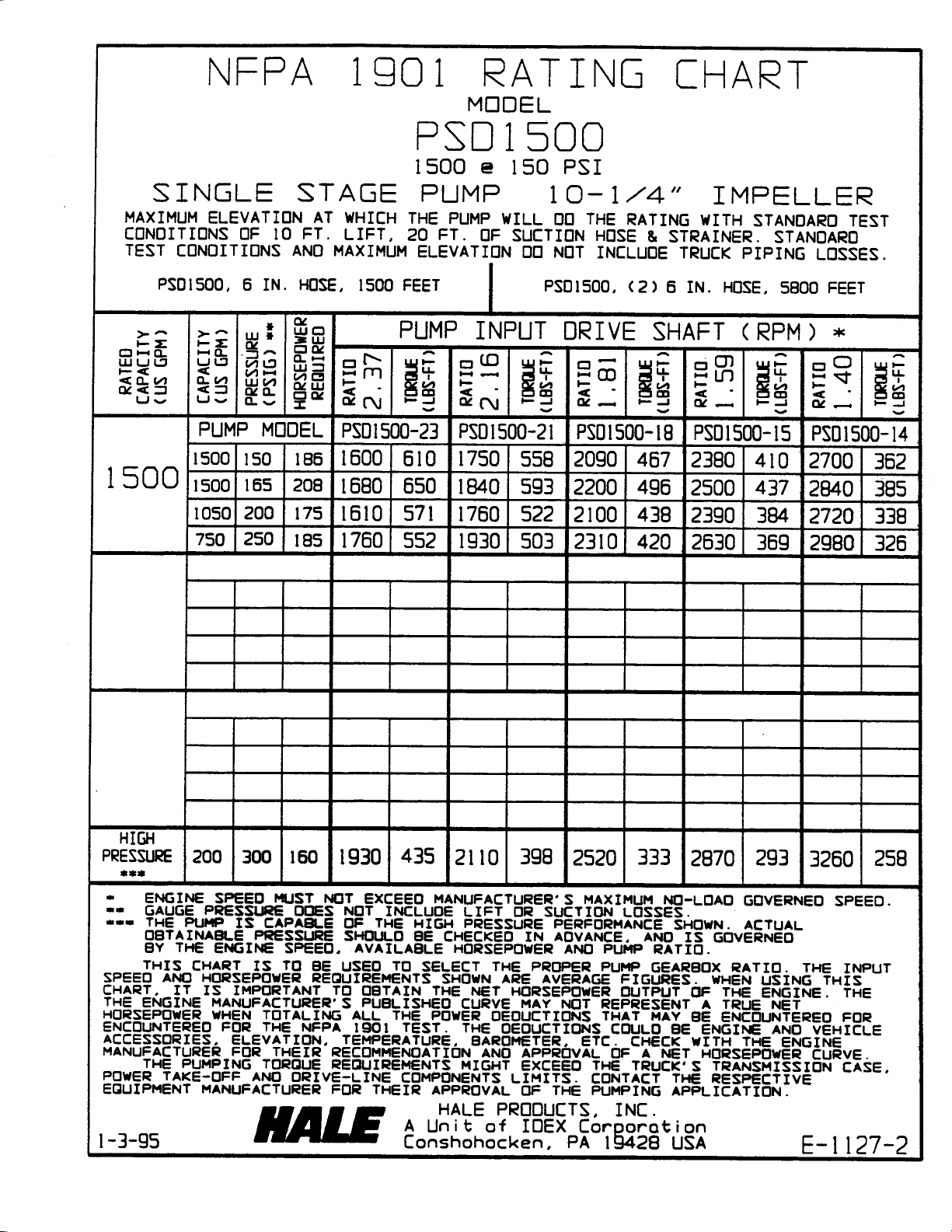
MODEL: PSD
SERIAL NO._______________
Failure to follow the operating, lubrication,
and maintenance requirements set forth in
the operating and instruction manual may
result in serious personal injury and/or damage to equipment.
A Hale pump is a quality product; ruggedly designed, accurately machined, carefully assembled and thoroughly tested. In order to maintain
the high quality of your pump and to keep it in a ready condition, it is important to follow the instructions on care and operation. Proper use and
good preventive maintenance will lengthen the life of your pump.
ALWAYS INCLUDE THE PUMP SERIAL NUMBER IN CORRESPONDENCE
n
HALE PRODUCTS INC.
A Unit of IDEX Corporation
700 Spring Mill Avenue
610/825-6300
www.haleproducts.com
n
Fax: 610/825-6440
Fire Suppression Division
n
Conshohocken, PA 19428

Limited Warranty
EXPRESS WARRANTY: Hale Products Inc. (“Hale”) hereby warrants to the original buyer that products manufactured by it are free of defects in material and workmanship for two (2) years or 2000 hours usage whichever
shall first occur. The “Warranty Period” commences on the date the original buyer takes delivery of the product
from the manufacturer.
LIMITATIONS: HALE’S obligation is expressly conditioned on the Product being:
• Subjected to normal use and service.
• Properly maintained in accordance with HALE’S Instruction Manual as to recommended services and
procedures.
• Not damaged due to abuse, misuse, negligence or accidental causes.
• Not altered, modified, serviced (non-routine) or repaired other than by an Authorized Service Facility.
• Manufactured per design and specifications submitted by the original Buyer.
THE ABOVE EXPRESS LIMITED WARRANTY IS EXCLUSIVE. NO OTHER EXPRESS WARRANTIES ARE
MADE. SPECIFICALLY EXCLUDED ARE ANY IMPLIED WARRANTIES INCLUDING, WITHOUT
LIMITATIONS, THE IMPLIED WARRANTIES OF MERCHANTABILITY OF FITNESS FOR A PARTICULAR
PURPOSE OR USE; QUALITY; COURSE OF DEALING; USAGE OF TRADE; OR PATENT INFRINGEMENT
FOR A PRODUCT MANUFACTURED TO ORIGINAL BUYER’S DESIGN AND SPECIFICATIONS.
EXCLUSIVE REMEDIES: If Buyer promptly notifies HALE upon discovery of any such defect (within the War-
ranty Period), the following terms shall apply:
• Any notice to HALE must be in writing, identifying the Product (or component) claimed defective
and circumstances surrounding its failure.
• HALE reserves the right to physically inspect the Product and require Buyer to return same to
HALE’S plant or other Authorized Service Facility.
• In such event, Buyer must notify HALE for a Returned Goods Authorization number and Buyer
must return the Product F.O.B. within (30) days thereof.
• If determined defective, HALE shall, at its option, repair or replace the Product, or refund the
purchase price (less allowance for depreciation).
• Absent proper notice within the Warranty Period, HALE shall have no further liability or obligation
to Buyer therefore.
THE REMEDIES PROVIDED ARE THE SOLE AND EXCLUSIVE REMEDIES AVAILABLE. IN NO EVENT
SHALL HALE BE LIABLE FOR INCIDENTAL OR CONSEQUENTIAL DAMAGE’ INCLUDING, WITHOUT
LIMITATION, LOSS OF LIFE; PERSONAL INJURY; DAMAGE TO REAL OR PERSONAL PROPERTY DUE TO
WATER OR FIRE; TRADE OR OTHER COMMERCIAL LOSSES ARISING, DIRECTLY OR INDIRECTLY, OUT
OF PRODUCT FAILURE.
Hale Products Inc. • A Unit of IDEX Corporation
700 Spring Mill Avenue • Conshohocken, PA. 19428
Phone: 610-825-6300 • Fax: 610-825-6440
IDEX CORPORATION
www.haleproducts.com

Hale Products Inc. •
A Unit of IDEX Corporation
700 Spring Mill Avenue •
Conshohocken, PA 19428
Phone: 610-825-6300 •
Fax: 610-825-6440
www.haleproducts.com
Material Return Policy
A Material Return Authorization (RGA) number must be requested from Hale Products
Inc., prior to returning any merchandise. Hale will refuse shipments that do not have
RGA markings. Hale will fax a copy of the RGA form. It is preferred that the RGA
form be used as the packing slip for the return.
Replacement parts, complete items, or accessories must be in new condition or are able to
be resold. All items must be marked with Hale Part numbers.
Material must reflect the original purchased item. Sub-components (or parts of end
items) will only be accepted at Hales discretion. Hale shall determine the value of subcomponents independent of replacement part pricing.
Special orders items are not returnable for credit. These items include Special
Configurations of product, replacement parts manufactured for specific repairs, and
customer specific material.
Material must be returned within 120 days of original purchase to qualify for the credit.
Material older than 120 days will be accepted at the discretion of Hale Products.
Material that meets all of the above criteria will have a 20% inspection and return fee
deducted from the credit value.
All special agreements for returns that do not qualify per the rules above, must be
documented, including inspection requirements, shall be documented in the RGA prior to
the return of the material.
Revised: 5-15-01-Rev#1

PSD-75 / 100 / 125 / 150 Fire Pump
p
p
General Specifications -
Type Single stage, gear driven, centrifugal pump. For applications using adequate PTO,
transfer cases and other
allow pump engagement.
Impeller Bronze, closed type, single suction with front and rear seal rings, mixed flow
and replaceable wear rings. 750 thru 1250 GPM -10-inches diameter, 1500 GPM
-10-1/4-inches diameter. Dynamometer tested.
Pump Shaft Heat treated stainless steel ground to finish size.
Packing Maintenance free mechanical seal.
Pump Case Nodular iron material (600 PSI hydrostatic pressure tests) with flanged discharge
outlet, auxiliary 3-inch NPTF discharge tap provided. Volute is rotatable 360° in
1/2° increments.
Inlet Flange Six-inch #77 style victaulic connector.
Discharge Flange Four-inch ASA #150 bolt pad.
ower transmission sources with clutch or other device to
Gauge Connection 1/4-inch NPTF on pump case.
Transmission All ball bearing construction. Precision helical cut and crown ground, Class 11,
treated gears. Splash type lubrication using SAE 20 weight oil. Equipped with
water cooled oil
and larger. Tach outlet with 90° adapter.
Gear Ratio 1.40, 2.16, or 2.37.
Drive Shaft Heat treated steel. 1-3/4 inch diameter with 7/16-inch key to accept commercially
available drive flanges and yokes.
Rotation Available in either standard opposite engine rotation or same as engine.
Mounting Rear bracket supported by three 1/2-inch bolts. Front of pump supported by the
apparatus builder.
Weight Standard weight less oil and all options - 275 pounds.
Miscellaneous
outlet and transmission are in vertical position unless otherwise specified.
Optional Volute position, horizontal transmission, inverted transmission, front heat jacket,
Unit is prime painted, two Operation/Maintenance Manuals are provided.
an assembly to reduce transmission temperatures on 1000 GPM
bronze package, special electric clutch package, primer, relief valves, master
and TRV.
Updated 2/2003
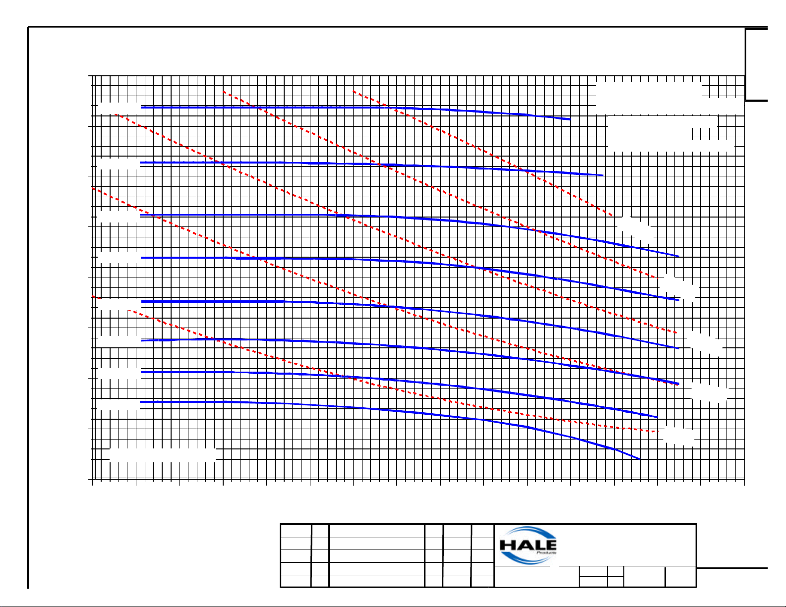
400
350
300
5200 RPM
4800 RPM
DSD/PSD/CSD/HFM/PSDB Pump Performance Curve
750-1250 GPM RATED PUMPS
Corrected to
Standard Conditions:
Barometer: 29.92 in HG
Water Temp: 60 F
Impeller P/N: 016-5130-00-0
E-1170A
4400 RPM
250
4000 RPM
200
3600 RPM
150
Net Pressure (psi)
100
3200 RPM
2800 RPM
2400 RPM
50
IMPELLER SPEED
0
0 100 200 300 400 500 600 700 800 900 1000 1100 1200 1300 1400 1500
250 HP
200 HP
150 HP
100 HP
50 HP
TYPICAL PUMP PERFORMANCE
BASED ON STANDARD CONDITIONS
AND ZERO SUCTION LIFT
REFER TO RATING CHART
FOR PUMP APPLICATION DATA
ECO NO
01-284 A
U.S. Gallons per Minute
REV CHANGED FROM
RELEASED FOR PRODUCTION
BY
LFM
DATE
08-06-01
APVD
MAL
COPYRIGHT ©
Not to be reproduced or used to
make other drawings or machinery.
HALE PRODUCTS, INC.
A Unit of IDEX Corporation
Conshohocken, PA 19428 USA
Drawn
LFM
MAL
Date: 08-06-01
Checked
E-1170A
400
350
5000 RPM
DSD/CSD/PSD Pump Performance Curve
1500 GPM RATED PUMPS
Corrected for
Standard Conditions
Barometer: 29.92"Hg
Water Temp: 60°F
Impeller P/N: 016-1050-00-0
E-1171A
300
4500 RPM
250
4000 RPM
200
3500 RPM
150
Net Pressure (psi)
100
3000 RPM
2500 RPM
50
IMPELLER SPEED
0
0 100 200 300 400 500 600 700 800 900 1000 1100 1200 1300 1400 1500 1600 1700 1800
40 HP
300 HP
250 HP
200 HP
160 HP
120 HP
80 HP
TYPICAL PUMP PERFORMANCE
BASED ON STANDARD CONDITIONS
AND ZERO SUCTION LIFT
REFER TO RATING CHART
FOR PUMP APPLICATION DATA
U.S. Gallons per Minute
ECO NO REV CHANGED FROM
01-346
RELEASED FOR PRODUCTION
A
BY
DLM
DATE APVD
09-10-01
MAL
HALE PRODUCTS, INC.
Conshohocken, PA 19428 USA
COPYRIGHT ©
Not to be reproduced or used to
make other drawings or machinery.
A Unit of IDEX Corporation
Drawn
DLM
MAL
Date: 09-10-01
Checked
E-1171A
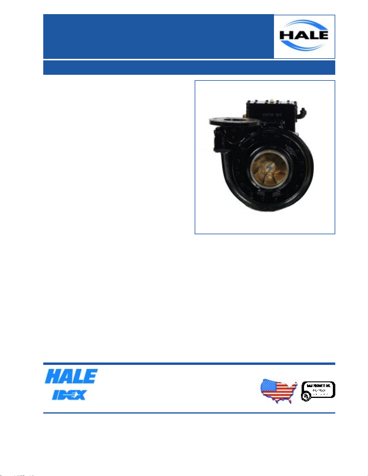
PSD Single Stage
PTO Pump
750 - 1500 GPM (2850 - 5678 LPM)
Features and Benefits
750 - 1500 GPM (2850 - 5678 LPM) NFPA
performance
Designed for modern diesel engines up to 500 HP
Compact design allows maximum truck design
flexibility
Technical Information
Type: Single-stage gear-driven centrifugal pump
designed for PTO drive, midship, or rear mount
applications
Impeller: Fine grain bronze, closed type, single
suction, dynamically balanced with front and rear
removable bronze sealing rings.
Pump Shaft: Heat treated stainless steel ground to
finish size
Pump Shaft Seal: Maintenance-free, self-adjusting
mechanical seal
Pump Case: Fine grain cast iron with a minimum
tensile strength of 30,000 PSIG. Flanged discharge
outlet. Auxiliary discharge opening accommodates
flanged connections up to 3-inch (76 mm). Tested to
600 PSIG at Hale's facilities.
Suction Flange: 6-inch Victaulic (150 mm)
Discharge Flange: 4-inch (100 mm)
Primer Connection: Customer supplied in
apparatus plumbing
Testing: Pump dynamometer tested at Hale facility
to ensure compliance with NFPA 1901 performance
standards.
Pump Gearbox: All ball bearing construction.
Precision cut and crown ground heat treated helical
gears. Splash lubrication system using SAE 30W oil.
Equipped with water-cooled oil pan to reduce
transmission temperatures on 1000 GPM and larger.
Gear Ratios: 1.40, 1.59, 1.81, 2.0, 2.16, or 2.37
Drive Shaft: Heat treated, 1-3/4" Keyed input
shaft
Weight: Standard weight less oil and all options -
280 lbs (127 kg)
Miscellaneous: Discharge outlet and transmission
are in the vertical position as standard
Optional Equipment
ESP Electric priming system
Relief Valve System
Horizontal or inverted transmission position
All bronze construction
Stainless steel valves
Hale Products
Fire Suppression Division
A Unit of IDEX Corp.
700 Spring Mill Avenue
Conshohocken, PA 19428
TEL: 610/825-6300
IDEX CORPORATION
Note: Hale Products Inc. cannot assume responsibility for product failure resulting from improper maintenance or
operation. Hale is responsible only to the limits stated in the product warranty. Product specifications contained in this
material are subject to change without notice. Bulletin 965 3/02 ©2002, Hale Products Inc
.
FAX: 610/825-9615
www.haleproducts.com
Hale Europe Ltd.
Fire Suppression Division
A Unit of IDEX Corp.
Charles Street
Warwick, CV34 5LR England
TEL: (0)1926 623600
FAX: (0)1926 623666
www.haleeurope.com
MADE IN THE USA

Definitions
Absolute pressure - The sum of gauge pressure and atmospheric pressure.
Approved Acceptable to the authority having jurisdiction.
Authority having jurisdiction - Refers to the organization, office or individual responsible for
approving equipment, an installation or a procedure.
Compound gauge - A gauge reading pressure from zero to maximum in pounds per square
inch (psi) and vacuum from 0 to 30 inches of mercury (Hg).
Discharge manifold - An enclosed housing, connected to the discharge side of pump case
and used to distribute water to several outlets.
Draft- Pumping condition using hard suction hose immersed in standing water which is below
the pump inlet connection.
Dynamic suction lift - The sum of the vertical lift and the friction and entrance loss due to the
flow through the suction strainers and hose.
Engine governor - A device installed on the engine designed to limit maximum RPM, often
used incorrectly to describe pump-engine governor or pump pressure control device.
Inlet screen - A device inserted in the pump inlet connection to restrict debris or other objects
from entering the pump.
Mechanical seal- A device to replace the packing box; it does not normally require periodic
maintenance.
Net pump pressure - The sum of the discharge pressure and the dynamic suction lift when
testing at draft, or the difference between the discharge pressure and the suction pressure
when testing from a hydrant or other source of water under positive pressure.
Packing box - Pump shaft sealing device to seal the pump from the atmosphere and to seal
internal water pressure. Incorporates packing or mechanical seal that is replaceable.
Primer- Device used to lower pressure in suction manifold of pump to induce water flow.
PSI - Pounds per square inch - Standard unit of pressure used in the fire service, eventually
will be replaced with the Pascal metric system.
PSIG - Pressure as read on the pressure gauge.
Pump case - Synonymous with volute but does not always have a volute shape with varying
area to enhance constant water velocity.
Pump outlet- An opening connected to the discharge manifold allowing water to exit during
pump operation.
Pump shift- A device to engage and disengage a fire pump.
Service tests - Tests made occasionally (at least annually) after the pump has been put into
service to determine if performance is still acceptable.
Siamese - A device used to divide water flow from one large hose to two or more smaller
hoses, often used to describe the discharge manifold used on front mounted fire pumps.
Single stage pump - Fire pump using a single impeller to induce water flow.
Steamer connection- Refers to pump suction nipple or main inlet connection.
Suction nipple - Pump inlet connection usually with male hose threads.
Vertical lift- The vertical distance from the surface of the water to the center of the pump
suction inlet.
Volute - Pump case wrapped around an impeller as a collector and having varying areas to maintain
constant water velocity.

P.T.O. PUMP OPERATION INSTRUCTIONS PUMPING FROM HYDRANT
1. Position chassis near hydrant and set parking brake. Place truck transmission in neutral.
CAUTION: Make sure that truck transmission shift quadrant lock is used. Place wheel
chocks in front and behind tires.
2. Attach one end of the suction hose to the hydrant and the other end to the pump suction
connection. Be sure the inlet strainer is installed and all drain valves are closed.
3. Open hydrant valve slowly to avoid rush of water.
4. Maintain engine idle speed and engage power take-off device.
5. Open discharge valve on pump.
NOTE: It is not necessary to use primer when pumping from hydrant. Accelerate
engine and adjust discharge valves to obtain desired pressure and volume. Set relief
valve operating pressure per the specific instructions supplied elsewhere in this
manual.
6. When using soft suction hose between pump and hydrant, do not use nozzles of larger
capacity than the hydrant will supply.
PUMPING FROM BOOSTER TANK
1. Position chassis and set parking brake. Place truck transmission in neutral. CAUTION:
Make sure that truck transmission shift quadrant lock is used. Place wheel chocks in front
and behind tires.
2. Close all drain valves.
3. Open valve in supply line from booster tank to pump suction.
4. Maintain engine idle speed and engage power take-off device.
5. Pull out primer handle. When discharge gauge registers pressure, open discharge line, and
release primer handle.
6. Accelerate engine and adjust discharge valves to obtain desired pressure and volume.
CAUTION: Do not try to pump a large volume of water, as suction supply line from
the tank will not handle it.

7. Set relief valve operating pressure per the specific instructions supplied elsewhere in this
manual.
PUMPING FROM DRAFT
1. Position chassis as close to the water source as possible and set parking brake. Place
truck transmission in neutral.
CAUTION: Make sure that truck transmission shift quadrant lock is used. Place wheel
chocks in front and behind tires. The pump will exceed the rated capacity on a ten
foot vertical lift, however, as the lift increases, performance and capacity will
decrease.
2. Attach hard suction hose to the suction nipple on pump and attach the hose strainer to the
other end. Be sure suction hose gasket and inlet strainer are in place, and all drain valves
are closed.
3. For best results, submerge suction strainer two feet or more in the water and avoid
pumping large volumes from shallow water.
4. Maintain engine idle speed and engage power take-off device. Pull out primer handle.
CAUTION: Care must be exercised not to operate pump without water as this can
seriously damage pump.
5. When discharge gauge registers pressure, open discharge line and release primer handle.
6. Accelerate engine and adjust discharge valves to obtain desired pressure and volume.- Set
relief valve operating pressure per the specific instructions supplied elsewhere in this
manual.

WARNING BUTTERFLY STYLE SUCTION VALVES
NOTICE: The PSD pump incorporates a butterfly style valve in the suction side of the
pump, or pumps utilizing large diameter delivery hose, REQUIRE the use of a suction
side relief valve of sufficient size and MUST be set at 150 PSI MAXIMUM. Do not
hydrostatic pressure test the butterfly valve above 150 PSI and make sure that it is in
the open position.
Most brands of butterfly valves REQUIRE modification for use. If the butterfly valve is supplied
by anyone other than Hale then contact our Engineering Department for the latest retrofit
requirements. Failure to stay within the above parameters releases Hale Products Inc. from all
liability resulting from the misuse or improper installation of this product.

Many Centrifugal Pump Troubles are Due to Air Leaks
Procedure to follow to detect possible air leaks:
A. Start engine with pump disengaged and with pump drained.
B. Tightly close pump drain valve as well as booster tank suction and discharge valves (if
connected to a booster tank). Tighten caps on suction and discharge openings. Then pull
out primer handle.
C. Observe hand on vacuum gauge until it reaches a stationary position; this should be 20
inches or over.
D. Release primer handle and carefully watch vacuum gauge hand. If hand drops back rapidly,
it indicates a leak, which must be located and corrected. If it stands stationary, or moves
back very slowly, it indicates either no leak, or a minor leak, which will not interfere with
satisfactory operation.
E. Should test indicate a leak in pump proper, the stuffing box may need adjustment, if
equipped with packing. If the pump is equipped with a mechanical seal, it may require
service.
F. Now remove discharge cap. If vacuum gauge hand returns toward zero, more rapidly than
before cap was removed, it indicates that the self-closing poppet valve within the discharge
manifold is not properly seated and this condition should be corrected.
G. When difficulty is experienced in locating an air leak, it may be found by connecting pump
suction to a hydrant. With hydrant pressure on pump, look for water leaks, any one of
which indicates a possible air leak. When connected to a booster tank, there may be an air
leak in booster line valves - in valve proper, or around valve stem. The former may
necessitate replacement of complete valve while the latter may be corrected by replacing
valve stem.
H. Do not overlook possibility of air leaks in suction hose or couplings. To test for such leaks,
connect suction hose to pump suction, place pump suction cap over the end of the suction
hose, and test in the same manner as described above as to the motion of the vacuum
gauge hand.
I. It is a very good idea to make periodic tests for air leaks. NOTE: Excessive air leakage
may delay, or even prevent priming.

Trouble Shooting Guide
Pump Fails to Prime or Loses Prime
1. Restriction at the Suction Strainer
a. Remove all leaves, dirt and other foreign material from the strainer.
b. Use extra caution when drafting from shallow water sources with mud, sand or gravel
bottom.
c. Keep the strainer off bottom by placing it inside a barrel with the top cut down, or use a
similar method.
2. Suction Lift too High
a. Suction lift should not be attempted over 20 feet, except at low altitudes with the
equipment in new condition.
3. Suction Strainer too Near the Surface.
a. When pumping large volumes of water, the strainer should be submerged at least two
feet below the surface.
4. High Point in Suction Line.
a. Suction hose should slope down from pump to source.
b. If a high point cannot be avoided, re-prime several times to avoid air pockets.
5. Primer Not Operated Long Enough.
a. A normal prime should be accomplished within 20 seconds at a 10-foot lift.
6. Defective Priming Line.
a. Check hose from pump to priming valve and also hose from priming valve to the electric
priming pump. Check for leaks or accumulations of foreign material.
b. If necessary, refer to the electric priming pump operation instructions supplied
elsewhere in this manual.
Pump Will Not Deliver Capacity
1. Insufficient Horsepower.
a. Check engine according to manufacturers instructions, supplied with truck.
b. See local truck service garage.
2. Engine RPM too Low at Full Throttle.
a. Engine operated at high altitudes, engine horsepower decreases about 3 percent per
1000 feet above sea level. Consult manufacturers instructions. Also due to insufficient
horsepower.
3. Pump Wear Rings excessively Worn.
a. Excessive wear will allow severe internal leakage from the pressure side of the pump
back to the suction side, reducing the net pump capacity and pressure.

Engine RPM Higher than Necessary for Desired Volume in Pressure
1. Restriction in Suction Hose Strainer or Impeller Vanes.
a. Inspect strainer to clear away all debris.
b. Pressure backwash will usually clear impeller vane when pump is topped.
c. Check condition of the suction hose. On an old, or defective hose, the liner may be
pulled loose when pumping, thus reducing the inside diameter of the hose itself.
2. Undersize Suction Hose.
a. When pumping at higher than normal lifts, or altitudes, use a larger suction.
3. Truck Transmission in Too Low a Gear.
a. Proper pumping gear is usually high, or direct drive. Consult apparatus instructions.
Pump Will Not Develop Sufficient Pressure
1. Often the remedies for low pump capacity will also correct low pressure.
2. Pump RPM too Low
a. Use a tachometer to check engine speed.
3. Pump Capacity Limits Pump Pressure.
a. Do not attempt to pump a greater volume of water at a given pressure than the pump
was designed to handle. Cavitation will result. Pump efficiency will be seriously impaired.
(NOTE: Prolonged pumping while pump is cavitating will damage impeller.)
b. Reduce volume by restricting discharge until the desired pressure is obtained.
Volume and Pressure
Capacity at 150 PSI
70% Capacity at 200 PSI
50% Capacity at 250 PSI

HALE PRODUCTS, INC.
RECOMMENDED PREVENTIVE MAINTENANCE PROCEDURE
1. Lubrication.
The PSD pump utilizes oil-bath type lubrication of all gears and bearings in the pump transmission.
Oil level in the transmission should be maintained even with the oil level plug, which is located near
the input shaft on the front side of the gear case. It is recommended that the oil be changed every
three months and after any prolonged period of pumping. Check oil level at regular intervals.
Should your department be fortunate enough to have only a few calls during the year, it will be
beneficial to operate the pump once a week - perhaps during drill work.
IMPORTANT - MIDSHIP PUMPS WITH SPLINED INPUT AND OUTPUT SHAFTS REQUIRE
THE USE OF SAE 20 WEIGHT NON-DETERGENT MOTOR OIL. DO NOT USE HEAVIER
OIL.
MIDSHIP PUMPS WITH FLANGED INPUT AND OUTPUT SHAFTS REQUIRE THE USE OF
SAE EP-90 LUBRICANT. ALL OTHER PUMPS (FRONT MOUNTS, PTOs, ETC.) REQUIRE
THE USE OF SAE 20-WEIGHT NON DETERGENT MOTOR OIL. DO NOT USE HEAVIER
OIL.
WARNING: Insufficient oil will result in serious damage to the bearings and other internal
parts. Too much oil or too heavy oil will result in unnecessary loss of power and
unnecessarily high oil temperature. Drain oil and renew at least every 12 months.
WARNING: It is normal practice to ship pump to builder without oil, oil must be added
before operating.
2. Drafting.
When pumping large volumes of water, the strainer should be submerged at least two feet below
the surface. Use extra caution when drafting from shallow water sources with mud, sand or gravel
bottom. Keep the strainer off bottom by placing it inside a barrel with the top cut down, or use a
similar method.
3. Salt Water Use.
After pumping salt water, pump from a hydrant for a few minutes to flush out the pump. Also, follow
this procedure after pumping excessively dirty water.
4. Cold Weather.
It is recommended that during cold weather the pump should be drained at all times, except when
kept in a heated fire house.
CAUTION: If long runs in very cold weather are expected (such as in rural areas), it is wise
to maintain a dry pump regardless of storage conditions.
5. Final Test Before Housing Engine after a Fire or Drill.
In addition to regular lubrication and maintenance to the pump, the following procedure is
recommended to assure proper operation under emergency conditions:
a) Open discharge valves and remove caps.
b) Close drain valve(s).
c) Tighten suction caps.

d) Pull a prime until the compound gauge reaches about 20 inches of vacuum.
e) Watch gauge - if vacuum drops more than one inch in 10 minutes, an air leak is present. All air
leaks must be corrected before the pump may be considered fully serviceable.
Ball Bearings
Ball bearings are the most common anti-friction bearings used today and offer a major contribution
to the life of a fire pump, during major maintenance you will have an occasion to remove or replace
ball bearings. Often an attempt is made to reuse them and sometimes they can be; however, when
doing so you are taking a serious gamble, particularly when you have invested a great deal of time
and money to dismantle, repair and reinstall the equipment only to have a bearing fail after a few
short hours of operation, again requiring further downtime and additional money spent. We do not
recommend this practice under any circumstance, however, we realize at times this must be
considered, when doing so they must be examined very carefully for pits, abrasion or other
damage, check the raceways very carefully for metal transfer and pits. When cleaning ball
bearings, be sure to use clean solvent; do not use contaminated solvent. Use clean air to blow the
solvent and foreign matter from the inside raceway, do not hold the inner race rigid and spin the
outer race with air pressure; this can cause metal transfer or embed small particles. Hold both
inner and outer races and blow through the open sections around the separation. After examination
and the bearing appears to be satisfactory, lubricate the raceway with light oil and then holding the
inner race between the fingers slowly rotate the outer race and feel for any catch, rough spots or
binds. If any are found then discard the bearing and secure a correct replacement. Your best
supply for the correct type and size is the pump manufacturer. If locally supplied bearings are used,
be sure it is an exact replacement. Do not interchange bearing types; they may also fail
prematurely.
We have sketched two similar bearings that have the same outside diameter, same inside diameter
and the same width, but if one of these bearings is used to replace the other one you may be
asking for trouble. Design engineers and bearing manufacturers have spent a great deal of time
and effort to achieve the correct combinations of loads, speeds and other contributing factors to
assure long and dependable service. When a bearing is inadvertently or hastily replaced without
due consideration, you should not expect your equipment to operate as designed.
The standard Conrad type bearing shown on the left contains five balls and is a so-called standard
bearing. It will withstand moderate radial and combined thrust loads; however, the maximum
capacity bearing shown on the right contains more balls due to the loading groove and will
withstand considerable higher radial loads but less thrust loading. This bearing can replace the
Conrad type when very little or no thrust load is present; however, never replace the maximum type
with a standard Conrad type, when a bearing has the loading groove as shown, it most certainly
indicates high radial and very little thrust loads are present.


Hale Products Inc.
Impeller Maintenance Recommended Clearances
This table lists recommended clearances for I.R.P.S. fire pumps (750 gpm to 1500 gpm). Be
sure to check your impeller for damage before proceeding to undersize wear rings. When
turning impellers to fit undersize rings, caution must be exercised that the seal ring surface
runs true with the bore within .002.
1/32 1/16
Standard Undersize Undersize
750/1250 gpm
A 6.067 6.036 6.005
6.069 6.037 6.006
1500 gpm
B 6.051 6.020 5.989
6.050 6.019 5.988
C 6.051 6.020 5.989
6.050 6.019 5.988
D 6.067 6.036 6.005
6.069 6.037 6.006
A 6.517 6.486 6.455
6.519 6.488 6.457
B 6.501 6.470 6.439
6.500 6.469 6.438
C 6.501 6.470 6.439
6.500 6.469 6.438
D 6.517 6.486 6.455
6.519 6.488 6.457

One Last Word
The PSD pump is an extremely rugged, dependable and versatile unit. Its transmission housing, gears, shafts, bearings, pump casings, and impeller are made of only the
finest materials. Years of engineering experience in hydraulic design and pump manufacturing stand behind beach unit and are in fact, the very reasons for its efficiency as
a hydraulic machine. Careful individual attention is given to each component as it is
machined to exact tolerances. Each pump is assembled by hand as a single unit. After
assembly and inspection, it is thoroughly tested under all phases of actual pumping
conditions.
In order that you realize the full value and advantages of this pump, it is suggested
that a few practices be carefully followed. All persons who will be responsible for the
actual operations of the pump should be thoroughly familiar with it and its operation,
both in theory and practice. This should include regular drills in pumping from draft,
hydrant, and booster tank. Careful instruction and practical experience will enable the
men and their equipment to work together as an effective firefighting team.
Regular and proper care of the pump itself and its related equipment (suction and
discharge hoses, gaskets, valves, etc.) is more important. A periodical schedule for
maintenance should be set up and strictly observed.

Pump Service Record
Pump Model ___________________ Pump Serial Number___________________
Check oil in gear case every 3 months; use SAE 20 non-detergent oil.
Change oil in gear case every 24 running hours.
Gear Case Oil Primer OIl Reservoir Comments or other Date/
Changed (Need Oil) Maintenance Performed Initials
YES NO YES NO

Pump Operation Log
Pump Model ___________________ Pump Serial Number___________________
Date Approximate Run time Type of Pumping
Hydrant-Draft-Booster Tank


HOSE FRICTON LOSS (PSI PER 100 FEET)
G.P.M Flowing
3/4 Booster
1 Booster
1-1/2 Hose
G.P.M Flowing
1-1/2 Couplings
1-3/4Hose with
1-1/2 Couplings
2 Hose with
2-1/2 Hose
3 Hose with
2-1/2 Couplings
10 13.5 3.5 95 14 8
20 44 6 125 24 13
30 99 14 150 35 18
40 176 24 4 175 47 25 6
50 38 7 200 62 32 8
60 54 9 225 10
70 12 250 13 5 4
80 15 275 15
95 22 300 18
125 38 325 22 8
150 54 350 25 8
500 20 17
750 45 38
1000
80
NOTE: Add 5 PSI for each story of building and each wye or siamese.
Friction Loss Calculations Courtesy IFSTA.
3 Hose
68

HOSE FRICTON LOSS (PSI PER 100 FEET)
s
GPM Flowing
3/4" Booster
1" Booster
GPM Flowing
1-1/2" Hose
1-3/4" Hose with
1-1/2" Couplings
2" Hose with
1-1/2" Couplings
2-1/2" Hose
3" Hose with
3" Hose
2-1/2" Coupling
10 13.5 3.5 95 14 8 500
20 44 6 125 24 13 750
30 99 14 150 35 18 1000
40 176 24 4 175 47 25 6 1250
50 38 7 200 62 32 8 1500
60 54 9 225 10 1750
70 12 250 13 5 4 2000
80 15 275 15
95 22 300 18
125 38 325 22 8
150 54 350 25 8
500 20 17
750 45 38
3-1/2" Hose
GPM Flowing
4" Hose
5" Hose
1000 80 68
NOTE: Add 5 PSI for each story of building and each wye or siamese.
Friction Loss Calculations Courtesy IFSTA.
HALE PRODUCTS INC.
A UNIT OF IDEX CORPORATION

DATA FOR PRACTICAL USE
WATER HORSE POWER =
GALLONS PER MINUTE X TOTAL HEAD IN POUNDS PER SQUARE INCH
1712
ONE GALLON WATER WEIGHS 8.33 POUNDS
ONE GALLON = 231 CUBIC INCHES
ONE CUBIC FOOT = 7.48 GALLONS
ONE POUND PER SQUARE INCH OF HEAD = 2.31 FEET HEAD OF WATER
ONE INCH OF MERCURY = 1.132 FEET OF WATER
ONE POUND PER SQUARE INCH = 2.0178 INCHES OF MERCURY = 27.68
INCHES OF WATER
POUNDS PER SQUARE INCH = FEET HEAD X .433
FEET HEAD = POUNDS PRESSURE X 2.31
ONE GALLON PER MINUTE X 3.785 = ONE LITER PER MINUTE
ONE CUBIC METER = 1000 LITERS
ONE IMPERIAL GALLON = 1.2 GALLONS
ONE POUND PER SQUARE INCH X .0690 = ONE BAR = .001 KPA
ONE BAR = 14.50 PSI
HALE PRODUCTS INC.
A UNIT OF IDEX CORPORATION
700 Spring Mill Avenue
Conshohocken, PA 19428
(610) 825-6300

HOSE FRICTON LOSS (PSI PER 100 FEET)
G.P.M Flowing
500
750
1000
1250
1500
1750
2000
3-1/2 Hose
9.5
20
34
53
74
4 Hose
3
6
10
16
23
31
5 Hose
5
8
13
18
25
32
NOTE: Add 5 PSI for each story of building and each wye or siamese.
Friction Loss Caclulations Courtesy IFSTA.
700 Spring Mill Avenue
Conshohocken, PA 19428
(610) 825-6300
www .haleproducts.com
HALE PRODUCTS INC.
A UNIT OF IDEX CORP.

HALE PRODUCTS INC.
A UNIT OF IDEX CORPORATION
GPM AT VARIOUS NOZZLE SIZES
1/2" 5/8" 3/4" 7/8" 1" 1-1/8" 1-1/4" 1-3/8"
PRESS.
NOZZLE
30 41 64 92 125 163 206 254 308
35 44 69 99 135 176 222 275 332
40 47 73 106 144 188 238 294 355
45 50 78 112 153 199 252 311 377
50 53 82 118 161 210 266 328 397
55 55 86 124 169 220 279 344 417
60 58 90 130 176 230 291 360 435
62 58 91 132 179 234 296 366 442
64 59 93 134 182 238 301 371 449
66 60 94 136 185 241 305 377 456
68 61 96 138 188 245 310 383 463
70 62 97 140 190 248 315 388 470
72 63 99 142 193 252 319 394 477
74 64 100 144 196 255 323 399 483
76 65 101 146 198 259 328 405 490
78 66 103 148 201 262 332 410 496
80 66 104 150 203 266 336 415 502
85 68 107 154 210 274 347 428 518
90 70 110 159 216 282 357 440 533
95 72 113 163 222 289 366 452 547
100 74 116 167 228 297 376 464 562
105 76 119 171 233 304 385 476 575
110 78 122 175 239 311 394 487 589
115 80 125 179 244 319 403 498 602
120 81 127 183 249 325 412 509 615

HALE PRODUCTS INC.
A UNIT OF IDEX CORPORATION
700 Spring Mill Avenue
Conshohocken, PA 19428
(610) 825-6300
GPM AT VARIOUS NOZZLE SIZES
1-1/2" 1-5/8" 1-3/4" 1-7/8" 2" 2-1/4" 2-1/2" 3"
PRESS.
NOZZLE
30 366 430 498 572 651 824 1017 1464
35 395 464 538 618 703 890 1098 1581
40 423 496 575 660 751 951 1174 1691
45 448 525 610 700 797 1009 1245 1793
50 473 555 643 738 840 1063 1313 1890
55 496 582 675 774 881 1115 1377 1982
60 518 608 705 809 920 1165 1438 2071
62 526 618 716 822 935 1184 1462 2105
64 535 628 728 835 950 1203 1485 2138
66 543 637 739 848 965 1222 1508 2172
68 551 647 750 861 980 1240 1531 2204
70 559 656 761 874 994 1258 1553 2236
72 567 666 772 886 1008 1276 1575 2268
74 575 675 783 898 1022 1293 1597 2299
76 583 684 793 910 1036 1311 1618 2330
78 590 693 803 922 1049 1328 1639 2361
80 598 702 814 934 1063 1345 1660 2391
85 616 723 839 963 1095 1386 1711 2465
90 634 744 863 991 1127 1427 1761 2536
95 651 765 887 1018 1158 1466 1809 2605
100 668 784 910 1044 1188 1504 1856 2673
105 685 804 932 1070 1217 1541 1902 2739
110 701 823 954 1095 1246 1577 1947 2803
115 717 841 976 1120 1274 1613 1991 2867
120 732 859 997 1144 1301 1647 2034 2928
 Loading...