


11/1/98
MASTER INTAKE VAL VE
DESCRIPTION, INSTALLATION AND
OPERATION
MANUAL
All Hale products are quality components: ruggedly designed, accurately machined, precision inspected, carefully assembled
and thoroughly tested. In order to maintain the high quality of your unit, and to keep it in a ready condition, it is important to
follow the instructions on care and operation. Proper use and good preventive maintenance will lengthen the life of your unit.
ALWAYS INCLUDE THE UNIT SERIAL NUMBER IN CORRESPONDENCE.
HALE PRODUCTS, INC. l A Unit of IDEX Corporation l 700 Spring Mill Avenue l Conshohocken, PA 19428 l TEL: 610-825-6300 l FAX: 610-825-6440
MANUAL P/N 029-0020-28-0, REV C, © 1998 HALE PRODUCTS, INC., PRINTED IN U.S.A.
Hale Products cannot assume responsibility for product failure resulting from improper maintenance
or operation. Hale Products is responsible only to the limits stated in the product warranty. Product
specifications contained in this material are subject to change without notice.

MASTER INTAKE VALVE
Table of Contents
SECTION PAGE
1 SAFETY .................................................................................................................... 1
2 GENERAL DESCRIPTION........................................................................................ 3
3 INSTALLATION ......................................................................................................... 6
4 OPERATION............................................................................................................ 17
5 MAINTENANCE ...................................................................................................... 20
6 TROUBLESHOOTING ............................................................................................ 27
7 PARTS LIST ............................................................................................................ 33
8 WARRANTY............................................................................................................ 37
9 INSTALLATION DIMENSIONS................................................................................ 38
NOTE TO INSTALLER
IMPORTANT: Warnings and cautions listed in Section 1 of this manual are necessary for safe
installation and operation of the Hale MIV. When developing individual apparatus operating
procedures make sure the warnings and cautions are incorporated as written.
Please provide a copy of the Hale Master Intake Valve manual to the end user of the equipment.
For additional manuals, contact Hale Products, Inc at (610) 825-6300.
Ask for Manual P/N 029-0020-28-0.
i

MASTER INTAKE VALVE
1
IMPORTANT NOTICE: Before attempting installation or operation of the Hale MIV read and
follow all safety precautions listed below. The warnings and cautions listed are necessary
for the safe installation and operation of the Hale MIV. When developing departmental
apparatus operating procedures make sure the warnings and cautions are incorporated
as written.
1. WARNING: The outlet of the relief valve
can flow large volumes of water under
pressure. Therefore, the discharge must
be piped in a manner that will not
expose personnel to high pressure water
streams.
2. WARNING: The suction of each
receiving pumper using large diameter
hose shall be equipped with a relief
valve with a maximum pressure setting
of not more than 10 PSI (0.7 BAR) over
the static pressure of the water source to
which it is connected or not more than
10 PSI (0.7 BAR) over the discharge
pressure of a supply pumper in relay. In
no event will the intake relief valve
pressure setting exceed the working
pressure of the hose being used.
3. WARNING: Per NFPA 1962 requirements,
large diameter hose marked “SUPPLY
HOSE” 3-½ to 5 inches (89 to 127 mm)
diameter shall not be used at operating
pressures exceeding 185 PSI (13 BAR).
4. WARNING: Per NFPA 1962 requirements,
large diameter hose marked “SUPPLY
HOSE” 6 inches (152 mm) diameter shall
not be used at operating pressures
exceeding 135 PSI (9 BAR).
5. WARNING: Never set intake relief valve
above hose manufacturers rated
pressure. Always use the lowest possible
relief valve setting to enhance operator
and equipment safety.
6. WARNING: Per NFPA 1962 requirements,
large diameter hose used to supply a
pumper from a hydrant or another
SAFETY
pumper shall be connected to the
pumper(s) and hydrant with a slight
downward bend to avoid kinking when
the water is turned on.
7. WARNING: Large diameter hose
presents a tripping hazard. Use care
when working around hose when in use.
8. WARNING: Male threads on relief valve
outlet are sharp and can cause severe
cuts. Be careful when working around
the exposed threads on the relief valve
outlet
9. WARNING: The relief valve spring is
under pressure and can cause a
projectile hazard. When disassembling
the relief valve, back relief valve
adjustment screw out to lowest setting to
relieve pressure on spring before
removing relief valve housing screws.
10. WARNING: Use tubing rated at the
maximum discharge pressure of the fire
pump, 500 PSI (34 BAR) minimum.
11. WARNING: Any electrical system has the
potential to cause sparks during
installation, service or repair. Take care
to eliminate explosive or hazardous
environments during installation, service
or repair.
12. WARNING: When a malfunction occurs
and the motor stalls the circuit breaker
will trip to disconnect electrical power to
the motor. If power remains to the valve
electrical system the motor and circuit
breaker could become extemely hot.
1

MASTER INTAKE VALVE
Care must be taken when removing
gearmotor cover.
13. WARNING: When initially charging large
diameter hose excessive air will be
present in the hose. This air must be bled
off while the hose is charging and prior
to opening the Hale MIV to prevent
receiving pump cavitation and possible
loss of prime.
14. WARNING: When the electric motor
driven valve is operated the manual
override handwheel will turn. Keep
hands, feet or loose clothing away from
the handwheel to prevent
entanglement.
15. WARNING: Keep hands and arms clear
of the valve disc when valve is being
operated without suction tube strainer or
suction tube in place.
16. WARNING: The Hale MIV is shipped with
a plastic plug in the ¾ inch NPT air
bleeder connection port. During
installation of the Hale MIV the plug must
be removed and an air bleeder control
valve, controllable at the pump
operator position, must be installed.
valve with a wrench while tightening
elbow.
19. CAUTION: Electric motor and wiring are
protected by a circuit breaker. DO NOT
remove or bypass the circuit breaker as
severe damage to the electric motor or
apparatus wiring could result during a
motor stall condition.
20. CAUTION: The Hale MIV is designed for
operation on 12 Volt DC negative
ground electrical systems only.
21. CAUTION: Follow NFPA requirements for
apparatus electrical wiring. Use
minimum 14 AWG, type SXL or GXL (SAE
J1128) wire. The wiring shall be
protected using 289
flame retardant, moisture resistant loom
or braid.
22. CAUTION: The stem on the top of the
valve disc extends approximately 1-½
inches into the operator assembly. The
bottom of the valve disc must be
removed first.
o
F (143 C) minimum
17. WARNING: If the optional Hale Air
Bleeder Valve (ABV) assembly IS NOT
installed, a warning placard must be
mounted on the operator panel next to
the air bleeder control stating:
“WARNING: ALL AIR MUST BE BLED FROM
INTAKE HOSE PRIOR TO OPENING MIV
VALVE .”
18. CAUTION: To prevent damage to the
valve body hold the hex outlet on the
2

MASTER INTAKE VALVE
2
GENERAL DESCRIPTION
The Hale Master Intake Valve is a NFPA
compliant large diameter intake valve that
is mounted in the pump suction tube
behind the pump operator panel. The valve
is a butterfly type valve that is available
either in manual or electric operation.
Safety features on the valve include an
integral relief valve and air bleeder valve
tap that vent to the atmosphere. The valve
assembly, less relief valve, is factory tested
to 600 PSI (41 Bar).
The Hale Master Intake Valve has a 6.4 inch
(163 mm) diameter bore with a butterfly
disc designed to provide minimum flow
restriction when the valve is open. The
unique design of the valve and butterfly
permits the valve to provide full water flow
up to 1500 GPM (5678 LPM) from draft
through a single 6 inch NST suction hose
when mounted on Hale pumps directly to
the main suction inlet under all standard
operating conditions. Due to the design of
the valve, there is minimum friction loss and
pressure drop across the valve.
When the valve is ordered as part of a Hale
Midship fire pump, the pump will pass UL
requirements up to 1500 GPM (5678 LPM)
from draft through a single 6 inch NST
suction hose with the valve in place. When
two valves are mounted to the fire pump
the pump can achieve UL flows up to 2000
GPM (7570 LPM) from draft through dual 6
inch NST suction hoses. The disc design also
permits easy maintenance and lubrication
of the valve disc. The disc is coated with
nitrile rubber material that is compatible
with most chemicals in use on the fire
ground.
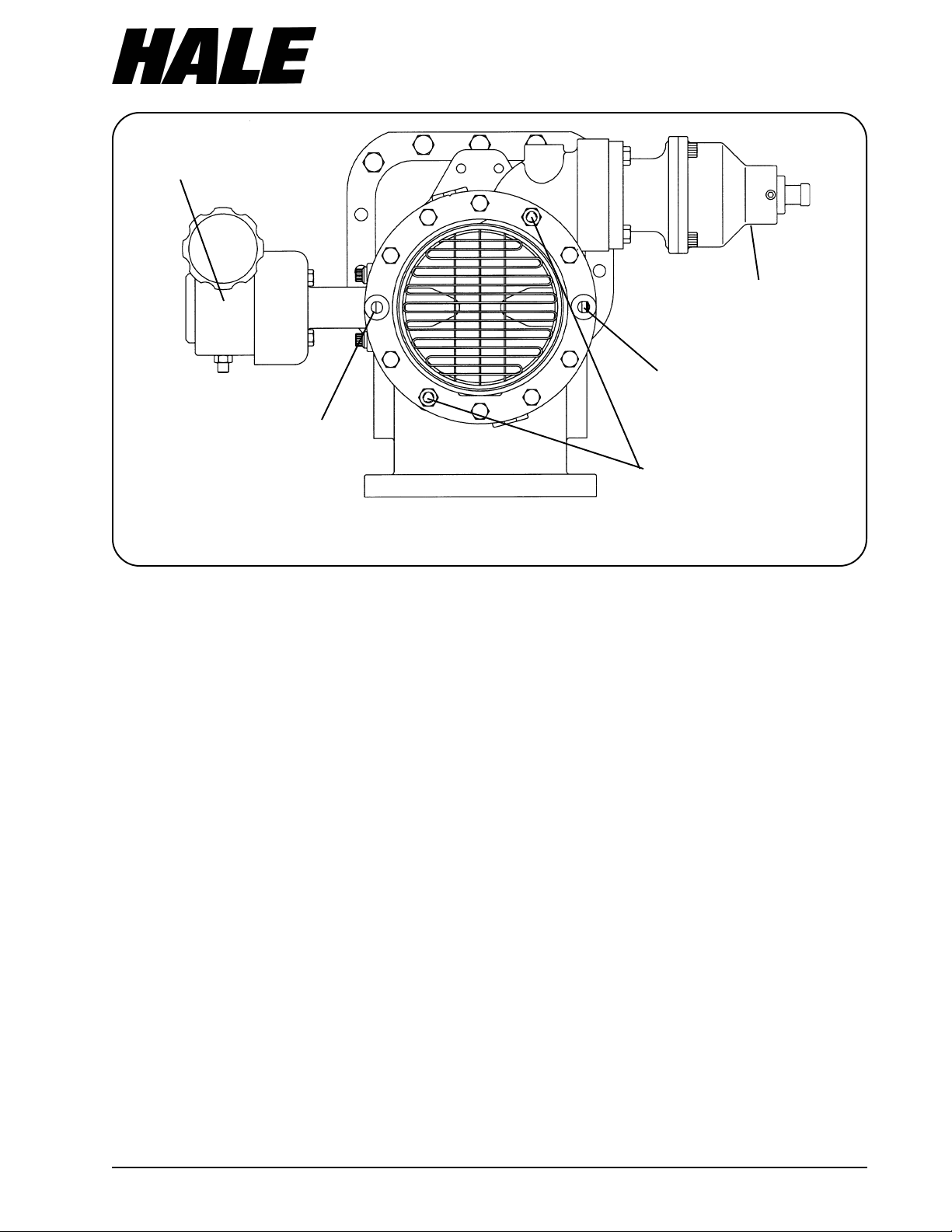
OPERATOR PANEL
PLACARD
TO +12 VDC
POWER SUPPLY
SUCTION
EXTENSION ON
MIDSHIP PUMP
ELECTRIC
MOTOR
PROTECTIVE
COVER
GEARBOX
AIR BLEEDER
CONNECTION
GEARBOX SHAFT
EXTENSION
(76 AND 81 INCH
PANELS)
OVERRIDE
PLACARD
OUTBOARD
PRIMING TAP
MANUAL
PANEL
Figure 1. Component Part Identification (Electric Valve)
RELIEF
VALVE
VALVE
BODY
VALVE
DISC
WATER DRAIN
CONNECTION
SUCTION
TUBE
MANUAL
OVERRIDE
HANDWHEEL
3

MASTER INTAKE VALVE
The valve is available configured for
manual operation using a panel mounted
handwheel (MIV-M) or for electric
operation using a panel mounted switch
(MIV-E) for remote control operation.
Whether the manual or electric operated
valve is installed, lights on the panel placard
will illuminate to indicate if the valve is
open, closed or traversing from one position
to the other.
Also provided with the electric valve is a
manual override handwheel that permits
valve operation from outside the operator
panel. No special tools or parts removal is
required.
The valve gear actuator, manual or electric,
is designed to move the valve disc from the
fully closed to full open position using 10
turns of the handwheel. The electric
operated valve will cycle from the fully
closed to full open position in no less than 3
seconds therefore meeting NFPA
requirements. The matched gear set is
designed to permit operation with minimal
torque even at high flows and pressures.
The design of the gear actuator also
permits the valve to be placed into a
partially open position if it is necessary to
gate the intake flow.
Master Intake Valves are provided with a ¾
inch NPT suction hose priming port. This port
is located near the relief valve mounting
flange on the valve body. During pump
operations when an MIV is installed on the
main pump suction it may be desirable to
pre-prime the suction hose so fire fighting
capabilities are not lost when switching from
tank to draft operations.
Since the valve mounts behind the operator
panel, between the suction tube extension
and the suction tube, or in-line for front and
rear suction piping, there is less panel
clutter, obstruction of valve handles or
chance for damage to the valve body due
to overhang beyond the apparatus running
board.
SUCTION
EXTENSION ON
MIDSHIP PUMP
GEARBOX
GEARBOX SHAFT
(76 AND 81 INCH
Figure 2. Component Part Identification (Manual Valve)
EXTENSION
PANELS)
POWER SUPPLY
TO +12 VDC
AIR BLEEDER
CONNECTION
OUTBOARD
PRIMING TAP
RELIEF
VALVE
VALVE
BODY
VALVE
DISC
WATER DRAIN
CONNECTION
SUCTION
TUBE
PANEL
PLACARD
HANDWHEEL
4

MASTER INTAKE VALVE
The surface between the mounting flanges
and Hale MIV valve body are sealed using
reliable o-ring seals in grooves machined in
the Hale MIV body.
Design of the relief valve permits the
discharge to be piped behind the operator
panel for increased operator and/or
bystander safety.
5

MASTER INTAKE VALVE
3
The unique design of the Hale Master Intake
Valve permits installation in the fire pump
suction tube behind the pump
compartment panel using a minimum of
space. The valve body is only 3-3/8 inches
(86 mm) wide and various suction tube
options are available to fit most standard
pump compartment widths. (Refer to Hale
Bulletin 596, reprinted in section 9 of this
manual, for various suction tube options.)
The side mounted valve is installed behind
the pump compartment panel between
the suction tube and suction tube extension
(Figures 1 and 2). The design of the relief
valve mounting flange permits rotation of
the relief valve to redirect the outlet of the
relief valve as necessary as well as remote
mounting. There are 2-½ inch female NPT
threads machined into the relief valve
mounting flange of the MIV valve to permit
remote mounting of the relief valve.
Bottom mounted valves are installed to
bottom of the suction tube extension for use
with front and/or rear suctions (Figure 4).
The valve may also be installed in-line or it
may be used with large auxiliary pumps.
Optional Hale 6 inch NPT threaded flanges
are available for use in these installations.
Whether installing the valve during new
construction or installing the valve as a
retrofit proper planning and equipment
layout will ensure smooth installation. The
Hale MIV has been designed to mount onto
a Hale midship pump without interference
to other suction and discharge connections
on the pump. The current revision of Plates
814A, 815A, 841A and 842A, reprinted in
Section 9 of this manual, provide the overall
mounting dimensions for various
configurations of the Hale MIV.
When ordered as part of a new midship fire
pump the valve will be pre-installed on the
INSTALLATION
fire pump and tested at the factory per
NFPA requirements. When installing the
midship pump on the apparatus it will be
necessary to install the relief valve
discharge piping, air bleeder, suction hose
priming and drain valve (steps A through J
in this section).
The following steps shall be followed when
installing the valve on a midship fire pump.
Steps A and B can be eliminated if the Hale
MIV is installed on the midship pump at the
factory.
A. MOUNTING OF SIDE SUCTION
VALVES (when not ordered as part of
midship pump)
NOTE: When installing the Hale MIV as a
retrofit it is highly recommended that the
standard suction extension be replaced
with the Hale P/N 178-0063-00-0 suction
extension. This is especially important on
apparatus with panel widths of 70, 72
and 74 inches to minimize panel
modification required. Refer to Section
9 of this manual for mounting dimension
drawings for assistance in planning
retrofit installations.
1. Determine the location of interferences
on the fire pump and the pump
operator panel. Proper planning and
layout of the pump operator panel will
reduce the potential interferences for
other operating equipment. The current
revision of Plate 814A and Plate 815A,
reprinted in Section 9 of this manual,
provide the overall mounting dimensions
for the Hale MIV.
2. Remove the cap screws that hold the
suction tube to the suction tube
extension. Remove the suction tube
from the pump. Be sure to remove all
old gasket or sealing material from the
6
GEARBOX
MASTER INTAKE VALVE
RELIEF
VALVE
STUD OR CAP
SCREW NOT USED
IN THIS HOLE
STUD OR CAP
SCREW NOT USED
IN THIS HOLE
STUDS PLACED IN
THESE HOLES
LOOKING INTO SUCTION TUBE FROM OUTSIDE PUMP
Figure 3. Stud Placement for MIV Installation
suction tube extension and suction tube
mating surfaces.
NOTE: Use only7/16-14 UNC X 4-¾ inches
long grade 5 zinc plated steel cap
screws,7/16-14 UNC X 5-¼ inches long
grade 5 zinc plated steel studs and7/1614 UNC zinc plated steel nuts to install
the Master Intake Valve and suction
tube to the suction tube extension.
NOTE: All cap screws, studs and nuts
must be locked in place using Loctite
#242 or equal thread sealing
compound.
NOTE: When the valve body is installed
make sure the valve disc is next to the
suction tube extension. The relief valve,
drain valve, air bleeder valve and
priming valve must be located on the
inlet side of the valve. When the Hale
MIV is properly orientated for installation
the gearbox will be located on the left
and the relief valve will be located at
the upper right. (See figure 3)
PANEL
3. Apply a coating of Loctite #242 or equal
thread sealing compound and install the
7
/16-14 UNC X 5-¼ inch long studs into
two holes of the suction tube extension.
Torque the studs to 40 lb-ft (54 N-m).
These studs are used to support the
valve and suction tube during
installation. The studs are installed in the
holes located at the 1 o’clock and 7
o’clock position on the suction tube
extension. (See figure 3)
4. Make sure the o-ring seals are seated in
the grooves on the valve body and coat
all sealing surfaces with a light coat of
general purpose grease.
5. Install the valve body and suction tube
over the studs taking care not to
damage the threads on the studs.
Apply a coat of Loctite #242 or equal
thread sealing compound and insert the
(8)7/16 -14 UNC x 4-¾ inch long grade 5
zinc plated steel cap screws through the
holes in the suction tube and thread into
the holes on the suction tube extension.
DO NOT tighten the cap screws until all
7

MASTER INTAKE VALVE
threads are started. Apply Loctite #242
or equal to the threads on the studs and
install the
7
/16-14 UNC grade 5 zinc
plated steel nuts on the studs.
NOTE: When installing the Hale Master
Intake Valve 8 suction tube cap screws,
2 studs and 2 nuts will be used. Cap
screws cannot be inserted where the
gearbox adapter (9 o’clock position)
and trunnion (3 o’clock position) are
located. See figure 3.
6. Tighten all suction tube cap screws and
nuts. Torque to 40 lb-ft (54 N-m) using a
cross pattern.
B. MOUNTING OF BOTTOM (FRONT/
REAR) SUCTION VALVES (when not
ordered as part of midship pump)
The Hale MIV-E can be mounted to the
bottom opening of Hale suction tube
extension P/N 178-0063-01-0 for use in front
and/or rear suctions. The bottom opening
of this extension is machined to accept
Hale 2417 series 12 bolt flanges. A special 6
inch NPT threaded flange Hale P/N 1150441-00-0 must be used when mounting the
Hale MIV-E on the bottom opening of this
suction tube extension. Ordinary flanges will
not provide proper clearance for the valve
disc.
When installing the Hale MIV-E in front or
rear suction piping do the following:
1. Determine the location of interference
on the fire pump and the pump
operator panel. Proper planning and
layout of the pump operator panel will
reduce the potential interference with
other operating equipment. Refer to the
current revision of Plate 841A and Plate
842A, reprinted in Section 9 of this
manual, for the overall mounting
dimensions for the Hale MIV.
NOTE: Use only 7/16-14 UNC x 5-¾ inch
long grade 5 zinc plated steel cap
screws, 7/16-14 UNC x 6-¼ inch long
grade 5 zinc plated steel studs and 7/1614 UNC zinc plated steel nuts to install
the Master Intake Valve and flange to
the suction tube extension.
TO OPERATOR
PANEL PLACARD
ELECTRIC
MOTOR
PROTECTIVE
COVER
GEARBOX
GEARBOX SHAFT
(76 AND 81 INCH
SUCTION EXTENSION
ON MIDSHIP PUMP
OUTBOARD
PRIMING TAP
AIR BLEEDER
6 INCH NPT
2417 FLANGE
EXTENSION
PANELS)
GEARBOX SHOWN LEFT SIDE FRONT
MANUAL
OVERRIDE
OPERATOR
SHAFT
MANUAL
OVERRIDE PANEL
PLACARD
OR RIGHT SIDE REAR
CONNECTION
Figure 4. Bottom Opening Mounting
RELIEF
VALVE
SUCTION EXTENSION
ON MIDSHIP PUMP
VALVE
BODY
WATER DRAIN
CONNECTION
TO OPERATOR
PANEL PLACARD
GEARBOX
6 INCH NPT
2417 FLANGE
GEARBOX SHOWN LEFT SIDE REAR
OR RIGHT SIDE FRONT
GEARBOX SHAFT
EXTENSION
(76 AND 81 INCH
PANELS)
MANUAL
OVERRIDE
OPERATOR
SHAFT
MANUAL
OVERRIDE PANEL
PLACARD
8
MASTER INTAKE VALVE
NOTE: All cap screws, studs and nuts
must be locked in place using Loctite
#242 or equal thread sealing
compound.
NOTE: When the valve body is installed
make sure the valve disc is next to the
suction tube extension. The relief valve,
drain valve, air bleeder valve and
priming valve must be located on the
inlet side of the valve. When the Hale
MIV is properly orientated for installation
the gearbox will be located towards the
front or rear of the apparatus
depending on which side of the pump
the valve is located. See figure 4.
2. If necessary the gearbox may be
rotated for proper installation. Refer to
Part J of this section for instructions on
how to rotate gearbox.
3. Coat the threads on one end of two
7/16-14 x 6-¼ inch long grade 5 studs
with Loctite #242 or equal and insert into
threaded holes on bottom of suction
tube extension. Torque studs to 40 ft-lb
(54 N-m). The studs are installed in holes
located at the 1 o’clock and 7 o’clock
positions, when viewed from below, on
the suction tube extension. See figure 3.
4. Orient valve so the relief valve and
gearbox are located as shown in figure
4.
5. Make sure the o-ring seals are seated in
the grooves on the valve body and coat
all sealing surfaces with a light coat of
general purpose grease.
Loctite #242 or equal and insert through
holes in the flange and thread into
bottom opening of suction tube
extension. Torque cap screws and nuts
to 40 ft-lb (54 N-m).
C. PLUMBING RELIEF VALVE
WARNING: Male threads on relief valve
outlet are sharp and can cause severe
cuts. be careful when working around
the exposed threads on the relief valve
outlet
WARNING: The outlet of the relief valve
can flow large volumes of water under
pressure. Therefore, the discharge must
be piped in a manner that will not
expose personnel to high pressure water
streams.
NOTE: The relief valve is attached to the
Hale MIV when shipped from the
factory. Apparatus configuration may
require that the relief valve be mounted
in a remote location. Step 1 below
provides procedures for mounting relief
valve in a remote location.
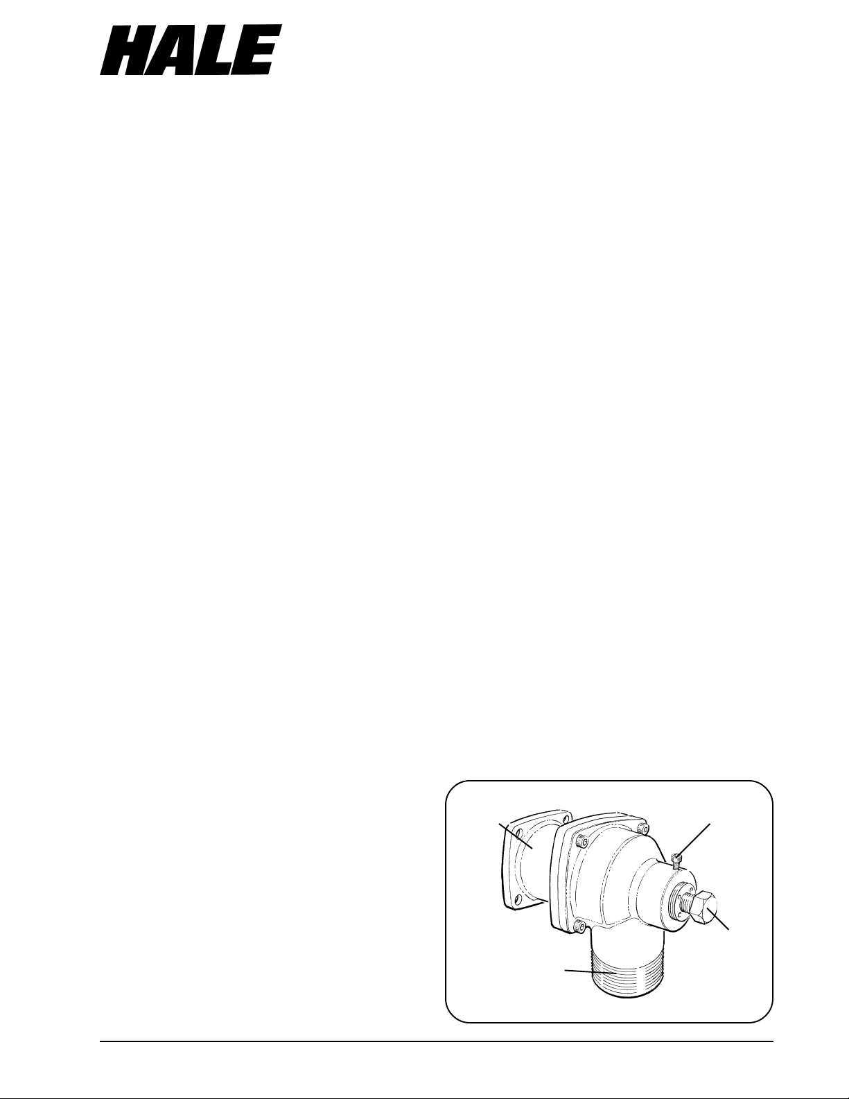
1. To Mount the relief valve in a remote
location do the following:
a. Remove the four7/16-14 UNC X 1-¼
inch long hex head cap screws that
secure the relief valve adapter and
relief valve to the mounting pad on the
Hale MIV body. (See figure 5)
RELIEF VALVE
MOUNTING
ADAPTER
ADJUSTMENT
LOCKING
SETSCREW
6. Carefully slide the valve and flange over
the studs making sure the studs align
with the holes in the valve body.
7. Apply Loctite #242 or equal to threads
on the studs and install two 7/16-14 nuts.
8. Coat the threads of eight 7/16-14 x 5-¾
inch long grade 5 cap screws with
ADJUSTMENT
2-½ INCH NPT
WATER OUTLET
CONNECTION
CAP SCREW
Figure 5. Relief Valve Adjustment
9

MASTER INTAKE VALVE
b. The relief valve mounting pad on the
Hale MIV valve body has 2-½ inch NPT
female threads, install a 2-½ inch NPT
threaded pipe nipple into the mounting
pad.
c. Screw a 2-½ inch NPT Hale type 115
4-3/8 inch bolt circle flange (Hale P/N
115-0070-00-0) onto the pipe nipple.
d. Making sure the relief valve
discharge is pointing down and away
from the operator position, attach the
relief valve adapter and relief valve to
the Hale 115 flange using a gasket, four
7
/16-14 UNC X 2-½ inch long grade 5 zinc
plated steel hex head cap screws and
four7/16-14 UNC zinc plated steel nuts.
Torque the cap screws and nuts to 40 lbft (54 N-m).
2. Attach a pipe or hose to the 2-½ inch
NPT outlet of the relief valve to direct the
discharge of the relief valve away from
the operator position. DO NOT restrict
the flow of water through this pipe.
Make sure the pipe is properly supported
to withstand the potential force of water
that can flow from the relief valve.
3. Two aluminum relief valve warning
placards, one wired to the relief valve
adjustment screw and the other with the
installation kit, are provided with the
Hale MIV. One of the placards must be
permanently affixed near the relief valve
adjustment screw and the other must be
mounted on the access panel for the
relief valve.
D. SUCTION HOSE WATER DRAIN
NOTE: On bottom mount valves the
drain connection on the valve is not
used. Remove the plastic shipping plug
and install a ¼ inch NPT pipe plug.
NOTE: Coat all pipe threads with a
suitable sealant before connections are
made.
1. Remove the plastic plug from the ¼ inch
NPT water drain connection on the
bottom of the valve body
2. Installa¼inchNPTx3/8inchtube
compression fitting or elbow into drain
hole.
3. Using 3/8 inch OD tubing rated at
maximum pressure of fire pump (500 PSI
(34 BAR) minimum) connect to an
individual drain valve located on the
pump operator panel.
E. AIR BLEEDER VALVE
WARNING: The Hale MIV is shipped with
a plastic plug in the ¾ inch NPT air
bleeder connection port. During
installation of the Hale MIV the plug must
be removed and an air bleeder control
valve, controllable at the pump
operator position, must be installed.
WARNING: If the optional Hale Air
Bleeder Valve (ABV) assembly IS NOT
installed, a warning placard must be
mounted on the operator panel next to
the air bleeder control stating:
“WARNING: ALL AIR MUST BE BLED FROM
INTAKE HOSE PRIOR TO OPENING MIV
VALVE .”
1. Remove the plastic shipping plug from
the ¾ inch NPT air bleed connection
that is located on the top of the valve
body and install an air bleeder control
valve that is controllable by the pump
operator. The discharge of the air
bleeder must be directed away from the
pump operator position. If the optional
Hale Air Bleeder Valve (ABV) is used,
refer to figure 6 and do the following:
2. Install ¾ inch NPT X ¼ inch NPT bushing
into the ¾ inch NPT tapped hole on the
valve body.
3. Install one of the ¼ inch NPT X3/8 inch
tube compression fittings into the ¼ inch
10

MASTER INTAKE VALVE
NPT threaded hole in the bushing.
4. Install the remaining ¼ inch NPT X
3
/8 inch
tube compression fitting into inlet of the
air bleeder valve body. Hold the valve
with a wrench.
CAUTION: To prevent damage to the
valve body hold the hex outlet on the
valve with a wrench while tightening
elbow.
5. Install the ¼ inch NPT X3/8 inch tube
compression elbow into the hex outlet of
the air bleeder valve. To prevent
damage to the valve body hold the hex
DISCHARGES TO
3/8 INCH O.D. TUBING
(PROVIDED BY INSTALLER
ATMOSPHERE
¼ INCH NPT x 3/8 INCH
TUBE COMPRESSION
FITTING
6. Using a
7. Remove the retaining nut from the valve
8. Insert the valve body into the panel
AIR BLEEDER
VALVE BODY
outlet on the valve with a wrench while
tightening elbow. Make sure the outlet
of the elbow is facing away from the
valve handle.
3
/32 inch Allen wrench, loosen the
setscrew and remove the valve handle
from the valve body.
body.
placard making sure the elbow is
oriented towards the top of the placard.
¼ INCH NPT x 3/8 INCH TUBE
COMPRESSION ELBOW
HOLD THIS HEX WHEN
TIGHTENING ELBOW
¼-20 UNC NUT
PANEL
PLACARD
¼-20 UNC x 1 INCH LONG
SCREW
AIR BLEEDER VALVE
RETAINING NUT
VALVE
HANDLE
¼ INCH NPT x 3/8 INCH
TUBE COMPRESSION
FITTING
¾ INCH NPT x ¼ INCH NPT
BUSHING
¾ INCH NPT AIR
BLEED TAPPED HOLE
ON VALVE BODY
Figure 6. Hale Air Bleeder Valve (ABV) Installation
¾ INCH NPT
OUTBOARD
PRIMING TAP
11

MASTER INTAKE VALVE
9. Install and tighten the retaining nut on
the valve body making sure the valve
remains in the correct orientation.
2.25 IN.
(57 MM)
0.75 IN.
(19 MM)
0.25 IN. (6 MM)
RADIUS TYPICAL
3.66 IN.
2.75 IN.
(70 MM)
0.28 IN. (7 MM)
DIAMETER HOLE
(4 PLACES)
0.25 IN.
(6 MM)
2.75 IN.
(70 MM)
(93 MM)
10. Install the valve handle and tighten
setscrew with allen wrench.
3.25 IN.
(83 MM)
1.63 IN.
(41 MM)
2.38 IN.
(60 MM)
0.53 IN.
(13 MM)
1.00 IN. (25 MM)
DIAMETER HOLE
0.28 IN. (7 MM)
DIAMETER HOLE
(4 PLACES)
A. ELECTRIC OPERATED VALVE
2.19 IN.
(56 MM)
0.25 IN. (6 MM)
RADIUS TYPICAL
3.34 IN.
(85 MM)
0.16 IN.
(4 MM)
0.20 IN.
(5 MM)
3.75 IN.
(95 MM)
1.13 IN.
(29 MM)
C. MANUAL OPERATED VALVE
0.28 IN. (7 MM)
DIAMETER HOLE
(4 PLACES)
1.00 IN. (25 MM)
DIAMETER HOLE
1.88 IN.
(48 MM)
3.75 IN.
(95 MM)
B. ELECTRIC OPERATED VALVE
MANUAL OVERRIDE HANDWHEEL
1.88 IN.
(48 MM)
2.25 IN.
(57 MM)
0.28 IN. (7 MM)
DIAMETER HOLE
(2 PLACES)
0.78 IN.
(20 MM)
0.31 IN.
(8 MM)
0.25 IN.
(6 MM)
RADIUS
TYPICAL
1.25 IN.
(32 MM)
D. OPTIONAL AIR BLEEDER VALVE
12
Figure 7. Master Intake Valve Panel Placard Mounting Dimensions

MASTER INTAKE VALVE
11. Determine location on the operator
panel for the air bleeder valve and cut
holes in the panel according to the
dimensions shown in figure 7D.
12. Install panel placard with valve
attached and secure in place using the
¼-20 UNC X 1 inch long cap screws and
¼-20 UNC nuts provided.
WARNING: Use tubing rated at the
maximum discharge pressure of the fire
pump, 500 PSI (34 BAR) minimum.
13. Connect a length of3/8 inch O.D. tubing
from the fitting on the Hale MIV valve
body to the fitting on the inlet of the air
bleeder valve.
14. Connect a length of
from the outlet of the elbow on the
outlet of the air bleeder valve and route
this tubing away from the operator
position. Make sure the outlet of this
tube is visible to the pump operator.
3
/8 inch O.D. tubing
additional priming pump is installed or a
three way valve is installed to control
priming.
G. PANEL PLACARDS, HANDWHEEL
AND HANDWHEEL EXTENSION
1. Locate and install the panel placard(s)
on the pump operator panel. Mounting
dimensions are provided in figure 7 to
assist in making cutouts for placard
mounting.
CAUTION: Electric motor and wiring are
protected by a circuit breaker. DO NOT
remove or bypass the circuit breaker as
severe damage to the electric motor or
apparatus wiring could result during a
motor stall condition.
WARNING: Any electrical system has the
potential to cause sparks during
installation, service or repair. Take care
to eliminate explosive or hazardous
environments during installation, service
or repair.
F. SUCTION HOSE PRIMING
NOTE: If suction hose priming
connection is not used, remove plastic
shipping plug and replace with ¾ inch
NPT pipe plug.
NOTE: Coat all fitting threads with a
suitable sealant before connections are
made.
1. Remove plastic plug from ¾ inch NPT
outboard priming tap located next to
relief valve.
2. Install a priming hose connection fitting
into ¾ inch NPT tapped hole
3. Using hose rated at 26 in. (760 mm) Hg
and 500 PSI (34 BAR) pressure, connect
the outboard priming tap to Priming
pump. Continue installation of priming
pump in accordance with procedures
provided with priming pump.
Dependent on configuration either an
CAUTION: The Hale MIV is designed for
operation on 12 Volt DC negative
ground electrical systems only.
NOTE: The electric panel placard wiring
harness is 96 inches (2438 mm) long. If
the panel layout requires extra wire
length a jumper (Hale P/N 513-0270-06-
0) is available or one may be fabricated
using minimum 14 AWG chemical
resistant wire with Packard WeatherPack
connectors. Care should be taken to
make sure the color code is maintained
per the original wiring. Wiring diagrams
are provided in the troubleshooting
section of this manual.
CAUTION: Follow NFPA requirements for
apparatus electrical wiring. Use
minimum 14 AWG, type SXL or GXL (SAE
J1128) wire. The wiring shall be
protected using 289oF (143 C) minimum
flame retardant, moisture resistant loom
or braid.
13

2. Connect the wiring harness from the
panel placard to the wiring harness from
the gearbox adapter. The Packard
WeatherPack end connectors are keyed
and will only assemble one way.
3. Connect +12 VDC power to the RED
pigtail provided using 14 AWG type SXL
or GXL (SAE J1128) wire. Make sure the
power supply is capable of providing 12
VDC power at 10 AMPS. Connect the
end of the BLACK wire to a ground point
on the chassis frame. Make sure the
wires are routed away from sources of
heat and avoid sharp edges. Make sure
all wires are protected with loom and
connections are sealed to protect them
from the under truck environment.
4. If required a handwheel extension is
provided in the installation kit. This
extension is used when truck panel
widths exceed 74 inch (1880 mm). The
extension is made to mount in one of
two positions.
MASTER INTAKE VALVE
WARNING: Keep hands and arms clear
of the valve disc when valve is being
operated without suction tube strainer or
suction tube in place.
6. Lubricate the valve bore and disc edges
using Sunoco Ultra Prestige 2EP grease
or equal. Cycle the valve to check for
smooth operation.
7. Hydrostatically test the fire pump and
valve in accordance with accepted
procedures.
H. RELIEF VALVE ADJUSTMENT
WARNING: Never set intake relief valve
above hose manufacturers rated
pressure. Always use the lowest possible
relief valve setting to enhance operator
and equipment safety.
WARNING: Per NFPA 1962 requirements,
large diameter hose marked “SUPPLY
HOSE” 3-½ to 5 inches (89 to 127 mm)
diameter shall not be used at operating
pressures exceeding 185 PSI (13 BAR).
a. The first position is for 81 inch (2060
mm) truck panel widths. The extension is
pushed on until the first hole in the
extension lines up with the hole in the
gearbox handwheel shaft.
b. The second position is for 76 inch
(1930 mm) truck panel widths. The
extension is pushed on all the way until
the second hole in the extension lines up
with the hole in the gearbox handwheel
shaft.
c. Two groove pins are provided in the
installation kit. On 81 inch panel widths
both groove pins are used. While on 76
inch panel widths only one pin is used.
5. Once pump operator panel is closed
install valve handwheel for manual
operator.
WARNING: Per NFPA 1962 requirements,
large diameter hose marked “SUPPLY
HOSE” 6 inches (152 mm) diameter shall
not be used at operating pressures
exceeding 135 PSI (9 BAR).
The relief valve is factory set to open at 125
PSI (9 BAR). The relief valve can be
adjusted to open from 75 to 250 PSI (5 to 17
BAR). Test and set relief valve as necessary
using the following procedures and figure 5:
1. Open operator panel and gain access
to the relief valve adjustment cap screw.
2. Make sure Master Intake Valve is closed
and install a pressure test cap on the
suction tube.
3. Connect a pressurized water source or
hydrostatic test pump and water supply
to the pressure test cap fitting.
14

MASTER INTAKE VALVE
4. Open water supply valve and air bleed
valve. Fill suction tube until water flows
from air bleed. Close air bleed.
5. Pressurize to desired set pressure in
accordance with the above warnings.
Observe whether relief valve opens or
remains closed at the desired pressure.
3
6. Using a
DO NOT REMOVE, the screw that locks
the pressure adjustment cap screw.
7. Using a7/8 inch open end wrench, turn
pressure adjustment cap screw to set
the relief valve pressure (clockwise to
increase opening pressure or
counterclockwise to decrease opening
pressure). Turn cap screw until relief
valve just opens or closes.
8. Once relief valve opens or closes turn
pressure adjustment cap screw ¼ turn in
the clockwise (increase pressure)
direction.
9. Lock the pressure setting by turning the
adjustment locking screw until tight.
Lock screw in place with wicking Loctite
#290 or equivalent.
10. Turn off water source and relieve some
pressure through the air bleeder
allowing relief valve to reset.
11. Reenergize water source and return the
pressure to the relief valve set point to
verify valve opening point. Repeat
adjustment procedures as necessary to
verify relief valve operation.
12. Open drain valve and drain water from
suction tube.
13. Disconnect water supply and remove
test cap from suction tube.
14. Close operator panel and return
/16 inch allen wrench loosen, BUT
apparatus to normal ready condition.
I. ROTATION OF GEARBOX (if necessary)
1. To avoid damage to switch rollers,
manually rotate the valve to the half
open position. (Approximately 5 turns
from either the fully open or fully closed
position.) This will place the switch
sequencing slot of the shaft midway
between both sets of switch rollers.
2. Remove the four 3/8-16 x 2-½ inch long
cap screws that hold the gearbox to the
gearbox adapter.
3. Carefully remove gearbox (MIV-M) or
gearmotor/gearbox assembly (MIV-E)
from gearbox adapter.
NOTE: The shaft and thrust washer (MIV-E
only) may come out with the gearbox.
Push shaft and thrust washer back into
place, being sure slot in end of shaft
seats over tang on valve disc and
sequencing slot is between switch rollers.
4. The gearbox may now be rotated in any
90° increment.
5. Reinstall the gearbox onto the gearbox
adapter by lining up square end of shaft
with square bore in gearbox.
6. Apply Loctite #242 or equal to four 3/816 x 2-½ inch long cap screws. Tighten
cap screws.
7. If valve is equipped with an electric
gearmotor and the gearmotor is
mounted horizontally, the gearmotor
cover must have the drain slots facing
down toward the ground. If the slots are
not facing the ground remove the four
#6-32 x 1/2 inch long screws and remove
the cover.
8. The circuit breaker, mounted on the
gearmotor, should be located on the
upper side of gearmotor. If not, remove
the four #6-32 x 1/2 inch long socket
15

MASTER INTAKE VALVE
head screws. Do not remove gearmotor
-the drive pin could drop out. Rotate
gearmotor so circuit breaker is located
toward top. Apply Loctite #242 or equal
to threads of #6-32 socket head screws
reinstall and tighten.
9. Be sure wiring connections are properly
and firmly attached. Slide strain relief in
cover cutout and slide cover over
gearmotor and adapter lining up holes.
Apply Loctite #242 or equal to threads of
#6-32 screws reinstall and tighten.
10. If valve is equipped with an electric
gearmotor and the gearmotor is
mounted vertically, the gearmotor
cover must have a drain hole added in
the bottom. Remove the four #6-32 x 1/2
inch long screws and remove the cover.
Drill a 5/16 hole through end of cover
and deburr. Slide strain relief in cover
cutout and slide cover over gearmotor
and adapter lining up holes. Apply
Loctite #242 or equal to threads of #6-32
screws reinstall and tighten.
16

MASTER INTAKE VALVE
4
OPERATION
WARNING: Per NFPA1962 requirements,
large diameter hose used to supply a
pumper from a hydrant or another
pumper shall be connected to the
pumper(s) and hydrant with a slight
downward bend to avoid kinking when
the water is turned on.
WARNING: Per NFPA1962 requirements,
large diameter hose marked “SUPPLY
HOSE” 3-½ to 5 inches (89 to 127 mm)
diameter shall not be used at operating
pressures exceeding 185 PSI (13 BAR).
WARNING: Per NFPA1962 requirements,
large diameter hose marked “SUPPLY
HOSE” 6 inches (152 mm) diameter shall
not be used at operating pressures
exceeding 135 PSI (9 BAR).
WARNING: The suction of each
receiving pumper using large diameter
hose shall be equipped with a relief
valve with a maximum pressure setting
of not more than 10 PSI (0.7 BAR) over
the static pressure of the water source to
which it is connected or not more than
10 PSI (0.7 BAR) over the discharge
pressure of a supply pumper in relay. In
no event will the intake relief valve
pressure setting exceed the working
pressure of the hose being used.
WARNING: When initially charging large
diameter hose excessive air will be
present in the hose. This air must be bled
off while the hose is charging and prior
to opening the Hale MIV to prevent
receiving pump cavitation and possible
loss of prime.
WARNING: Large diameter hose
presents a tripping hazard. Use care
when working around hose when in use.
AIR BLEEDER VALVE
1. Using standard departmental operating
procedures connect large diameter
hose from the supply pumper to the
receiving pumper.
2. Make sure the Hale MIV on the receiving
pumper is in the CLOSED position.
3. Open air bleeder valve by turning the
valve handle ¼ turn counterclockwise to
the OPEN position(dashed lines). (See
figure 8 D).
4. Have supply pumper energize the large
diameter hose and observe the air
bleeder discharge tube end. When
water flows from the air bleeder
discharge tube end, close the air
bleeder valve by turning the valve
handle ¼ turn clockwise to the CLOSED
position.
5. Operate the Hale MIV using the
procedures that follow.
ELECTRIC MOTOR OPERATED VALVE
(HALE MIV-E)
1. Energize 12 vdc power to pump
operator panel.
NOTE: As the valve is traversing from the
CLOSED to OPEN position (or OPEN to
CLOSED position) the yellow lamp will be
illuminated.
WARNING: When the electric motor
driven valve is operated the manual
override handwheel will turn. Keep
hands, feet or loose clothing away from
the handwheel to prevent
entanglement.
17

MASTER INTAKE VALVE
2. To open valve, push toggle switch
(figure 8 A) to the OPEN position and
hold until the green OPEN indicator
lights. If apparatus configuration
permits, observe the manual override
handwheel on the operator panel to
make sure the valve is turning. Release
the switch.
3. To close valve, push toggle switch to the
CLOSED position and hold until the red
CLOSED indicator lights. If apparatus
configuration permits, observe the
manual override handwheel on the
operator panel to make sure the valve is
turning. Release the switch.
MANUAL HANDWHEEL OPERATED
VALVE (HALE MIV-M)
NOTE: As the valve is traversing from the
CLOSED to OPEN position (or OPEN to
CLOSED position) the yellow lamp will be
illuminated.
1. To open the valve, turn handwheel
(figure 8 C) in the direction indicated by
the arrow on the panel placard until the
green OPEN indicator lights.
2. To close the valve, turn handwheel in
the direction indicated by the arrow on
the panel placard until the red CLOSED
indicator lights.
2. To close the valve, turn handwheel in
the direction indicated by the arrow on
the panel placard until the handwheel
stops.
COLD WEATHER OPERATION
During extremely cold weather the pump
and Hale MIV must be completely drained
to prevent ice formation and possible
damage. During cold weather operation
use the following procedure for continued
reliable operation.
1. Immediately after completion of
operations drain and disconnect the
large diameter hose. Open all
apparatus suction valves, discharge
valves, Hale MIV and drain valves.
Remove the suction tube caps. Permit
water to drain completely from the
pump and piping.
2. After pump is completely drained
replace all caps and close all valves.
The Hale MIV should be kept in the
closed position during cold weather.
WARNING: When the electric motor
driven valve is operated the manual
override handwheel will turn. Keep
hands, feet or loose clothing away from
the handwheel to prevent
entanglement.
MANUAL OVERRIDE (Electric Operated
Valve Only)
The electric motor operated valve has a
panel mounted handwheel to open or
close the valve in the event power is not
available from the apparatus electrical
system. To operate the valve in the event
of apparatus electrical power failure use
the following procedures:
1. To open the valve, turn handwheel
(figure 8 B) in the direction indicated by
the arrow on the panel placard until the
handwheel stops.
18
3. If, during cold weather the formation of
ice in the pump suction tube prevents
normal opening of the Hale MIV-E, the
valve disc may be freed by repeatedly
moving the toggle switch (figure 8 A) on
the operator panel from OPEN to
CLOSED position jogging the valve disc
to release the ice. Repeat movement of
the toggle switch as many times as
necessary to break the disc free.
Observe the manual override
handwheel to determine when disc is
free and valve is operating.

4.25 IN.
(108 MM)
1.13 IN.
(29 MM)
3.50 IN.
(89 MM)
MASTER INTAKE VALVE
4.00 IN.
GREEN
LAMP
AMBER
LAMP
RED
LAMP
(102 MM)
3.10 IN.
(79 MM)
4.00 IN.
(102 MM)
2.00 IN.
(51 MM)
TOGGLE
SWITCH
A. ELECTRIC OPERATED VALVE
RED
LAMP
5.37 IN.
(136 MM)
AMBER
LAMP
GREEN
LAMP
4.50 IN.
(114 MM)
1.50 IN.
(38 MM)
3.25 IN. (83 MM)
DIAMETER
HANDWHEEL
B. ELECTRIC OPERATED VALVE
MANUAL OVERRIDE HANDWHEEL
3.13 IN.
(80 MM)
2.09 IN.
(53 MM)
3.00 IN.
(76 MM)
2.63 IN.
(67 MM)
1.31 IN.
(33 MM)
5.00 IN. (127 MM)
DIAMETER
C. MANUAL OPERATED VALVE
Figure 8. Master Intake Valve Panel Placards
HANDWHEEL
VALVE HANDLE
D. OPTIONAL AIR BLEEDER VALVE
19

MASTER INTAKE VALVE
5
After each use:
1. Visually inspect the valve to make sure
2. If the system was operated with salt
3. Cycle the valve to make sure the valve
VALVE DISC REPLACEMENT:
If inspection of the valve disc indicates that
replacement is necessary order valve disc
replacement kit (Hale P/N 546-1620-00-0)
and proceed as follows:
1. To avoid damage to switch rollers,
MAINTENANCE
there is no debris caught between the
valve body and valve disc.
water, foam or contaminated water,
flush valve and pump with fresh water in
accordance with departmental
procedures.
still operates smoothly. Apply Sunoco
Ultra Prestige 2EP grease or equal to
valve disc edges and to valve bore as
necessary.
manually rotate the valve to the half
open position. Approximately 5 turns
from either the fully open or fully closed
position. This will place the switch
sequencing slot in the valve shaft
midway between both sets of switch
rollers.
primer tubing and drain tubing from the
valve body.
5. Remove the cap screws and nuts, then
remove the suction tube and valve from
the fire pump.
6. Take the valve body to a clean work
area and clamp into a vise or other
stable work holding device being
careful not to damage the valve sealing
surfaces.
7. Remove the four
cap screws that hold the gearbox to the
gearbox adapter.
8. Carefully remove gearbox (MIV-M) or
gearmotor/gearbox assembly (MIV-E)
from gearbox adapter.
NOTE: The shaft and thrust washer
(MIV-E) may come out with the gearbox.
If not, remove shaft and thrust washer.
9. Remove the two7/16-14 x 1 inch long
counterbore screws that holds the
gearbox adapter to the valve body.
Remove the gearbox adapter from the
valve body.
3
/8-16 x 2-½ inch long
WARNING: Keep hands and arms clear
of the valve disc when valve is being
operated without suction tube strainer or
suction tube in place.
2. Remove valve handwheel and open the
operator panel.
3. Tag and disconnect the electrical wires
from the valve.
4. Disconnect the relief valve discharge
piping, air bleeder tubing, outboard
20
10. Remove the trunnion from the bottom of
the valve body using a 1-½ inch socket.
CAUTION: The stem on top of the valve
disc extends approximately 1-½ inches
into the gearbox adapter bore. The
bottom of the disc, at the trunnion end,
must be removed first and then the disc
must be slightly rotated for the stem to
clear the bore.
11. Remove the old disc from the valve
body.

MASTER INTAKE VALVE
12. Clean and inspect all components for
damage and/or excessive wear.
Replace those components beyond
repair.
13. Install a new o-ring into the groove on
the valve disc stem. Apply a light coat
of Sunoco Ultra Prestige 2EP grease or
equal to the stem, o-ring and pivoting
surfaces of the new disc.
14. Install the new disc into the valve body
by inserting the stem end first. The disc
must be slightly rotated for the stem to
clear the bore. With the disc now
positioned in the fully open position,
push the trunnion end of the disc into
position. This will take some force to get
disc into position; however, well
lubricated pivot points greatly help.
15. Once disc is in place, roughly center
both the stem and trunnion ends in their
respective valve body bores.
16. Apply a light coat of Sunoco Ultra
Prestige 2EP grease or equal to the stem
and gearbox adapter pilot bore, as well
as, the bore for the trunnion pin.
17. Place a new o-ring on the trunnion.
Apply a light coat of Sunoco Ultra
Prestige 2EP grease or equal to the oring and pin diameter. Apply Loctite
#242 or equal to the threads on the
trunnion. Insert the trunnion into the
valve body and tighten using a 1-½ inch
socket wrench. Torque the trunnion to
120 lb-ft (163 N-m).
19. If switches need to be replaced refer to
instructions on MICRO SWITCH
REPLACEMENT.
20. Install a new gasket to gearbox adapter.
21. Rotate the valve disc to its half open
position. Apply a light coat of Sunoco
Ultra Prestige 2EP grease or equal to the
valve shaft. Insert the shaft into the
gearbox adapter making sure that the
slot in the end of the shaft lines up with
the tang on the end of the valve disc
stem and that the switch sequencing
slot is midway between both sets of
switch rollers. On MIV-E type valves
install the thrust washer over the square
end of the shaft. Lightly grease the top
surface of the thrust washer.
22. Reinstall the gearbox onto the gearbox
adapter by lining up square end of shaft
with square bore in gearbox.
23. Apply Loctite #242 or equal to four3/8-16
x 2-½ inch long cap screws. Tighten cap
screws.
24. Apply a light coat of Sunoco Ultra
Prestige 2EP grease or equal to the valve
bore and the disc edges.
25. Install valve and suction tube on the fire
pump. Apply a coat of Loctite #242 or
equal to threads of cap screws and nuts
before installing. Torque cap screws and
nuts to 40 lb-ft (54 N-m).
26. Connect electrical wires.
18. Place a new o-ring into the groove on
the gearbox adapter. Apply a light coat
of Sunoco Ultra Prestige 2EP grease or
equal to the o-ring and pilot diameter,
as well as the bore in the gearbox
adapter. Install the gearbox adapter
into the valve body. Reinstall the two
7
/16-14 x 1 inch long counterbore screws,
but do not completely tighten.
27. Operate the valve to the closed position
28. To complete the installation the red
(closed) lamp/motor operation versus
disc position timing must be set. Refer to
MICRO SWITCH REPLACEMENT steps 23
through 34.
21

MASTER INTAKE VALVE
MICRO SWITCH REPLACEMENT:
If inspection or if troubleshooting indicates
that replacement is necessary order switch
replacement kit (Hale P/N 200-1210-50-0) for
MIV-M or switch replacement kit (Hale P/N
200-1210-52-0) for MIV-E and proceed as
follows:
1. To avoid damage to switch rollers,
manually rotate the valve to the half
open position. Approximately 5 turns
from either the fully open or fully closed
position. This will place the switch
sequencing slot in the valve shaft
midway between both sets of switch
rollers.
WARNING: Keep hands and arms clear
of the valve disc when valve is being
operated without suction tube strainer or
suction tube in place.
2. Remove valve handwheel and open the
operator panel.
3. Tag and disconnect the electrical wires
from the valve.
4. If there is enough room to remove the
gearbox and valve shaft (approximately
4-¼ inches) the valve may not have to
be removed from the truck, skip to step
8.
8. Remove the four3/8-16 x 2-½ inch long
cap screws that hold the gearbox to the
gearbox adapter.
9. Carefully remove gearbox (MIV-M) or
gearmotor/gearbox assembly (MIV-E)
from gearbox adapter.
NOTE: The shaft and thrust washer
(MIV-E) may come out with the gearbox.
If not, remove the shaft and thrust
washer.
10. Remove the two #10-24x½longhex
washer head screws that hold the switch
plate assembly to the gearbox adapter.
Also loosen the strain relief nut on the
gearbox wiring harness.
11. Carefully remove the switch plate
assembly from the gearbox adapter by
feeding the wiring harness through strain
relief and pulling switch plate assembly
out gearbox adapter opening. Only
feed out enough wiring harness to get
access to the wire terminals on the
switches.
12. Disconnect wire terminals from switches.
Remove the four #4-40 screws that hold
the switches to the switch plate.
5. Disconnect the relief valve discharge
piping, air bleeder tubing, outboard
primer tubing and drain tubing from the
valve body.
6. Remove the six cap screws and two nuts
that hold the suction tube and valve to
the fire pump. Remove the suction tube
and valve.
7. Take the valve body to a clean work
area and clamp into a vise or other
stable work holding device being
careful not to damage the valve sealing
surfaces.
22
13. Refer to figure 9. The manual valve
(MIV-M) uses two switches and four #440x½inchlongscrews. Theelectric
valve (MIV-E) uses four switches, two
spacers and four #4-40 x 1 inch long
screws. Mount switches to switch plate
and apply a coat of Loctite #242 or
equal to threads of screws and install
screws.
IMPORTANT: Pinch switches toward each
other when tightening screws (See figure
10. Torque screws to 5 lb-in (0.6 N-m).
14. If previously removed, insert the gearbox
wiring harness through the ¾ inch NPT

MASTER INTAKE VALVE
THRUST
WASHER
MIV-E GEARMOTOR/
GEARBOX ASSEMBLY
MICRO SWITCH
(4 REQUIRED MIV-E)
(2 REQUIRED MIV-M)
SHAFT
(MIV-E) #4-40 X 1 SCREW
(MIV-M) #4-40 X ½ SCREW
WIRING
HARNESS
GASKET
SPACER
(MIV-E)
SHAFT
MIV-M
GEARBOX
GEARBOX
ADAPTER
SWITCH
#10-24 X ½
SCREW
PLATE
3
/8 -16 X 2-½
CAP SCREW
Figure 9. Micro Switch Replacement
tap in the gearbox adapter. Tighten
fitting in ¾ inch NPT tap. Do not tighten
strain relief nut. Push wires through strain
relief, enough to easily attach wires to
switches. Refer to wiring diagrams figure
12 for MIV-M manual valves or figure 13
for MIV-E electric valves. On electric
valves the switches mounted closest
(lower) to switch plate operate motor,
while the upper switches operate the
lights.
15. Carefully pull back on wiring harness
and at the same time insert switch plate
assembly into gearbox adapter.
16. Center switch plate assembly over the
shaft bore. On newer models there is a
raised pilot that switch plate centers on.
Rotate switch plate to align mounting
holes. Apply a coat of Loctite #242 or
equal to threads of two #10-24x½inch
long hex washer head screws. Torque
screws to 22 lb-in (2.5 N-m).
17. Tighten strain relief nut.
18. Install a new gasket to gearbox adapter.
19. Rotate the valve disc to its half open
position. Apply a light coat of Sunoco
Ultra Prestige 2EP grease or equal to the
valve shaft. Insert the shaft into the
gearbox adapter making sure that the
slot in the end of the shaft lines up with
the tang on the end of the valve disc
stem and that the switch sequencing
slot is midway between both sets of
switch rollers. On MIV-E type valves
install the thrust washer over the square
end of the shaft. Lightly grease the top
surface of the thrust washer.
23

MASTER INTAKE VALVE
PINCH MICRO SWITCHES WHERE INDICATED BY
ARROWS WHILE TIGHTENING SCREWS
Figure10. Micro Switch Tightening
20. Reinstall the gearbox onto the gearbox
adapter by lining up square end of shaft
with square bore in gearbox.
21. Apply Loctite #242 or equal to four
x 2-½ inch long cap screws. Tighten cap
screws.
22. Apply a light coat of Sunoco Ultra
Prestige 2EP grease or equal to the valve
bore and the disc edges.
3
/8-16
26. Slightly loosen the two
long counterbore screws that hold the
gearbox adapter to the valve body.
27. Manually turn back gearbox handwheel
a small amount until gearbox and
gearbox adapter are free to move. Find
the mid position of this free play and
tighten the two mounting screws.
28. Operate the valve to the open position,
then:
a. Manual valves (MIV-M)
a) Manually operate back to the
closed position. Stop when the red lamp
is lit.
b. Electric valves (MIV-E)
a) Use gearmotor to operate valve
to the closed position and allow the
switches to stop rotation.
b) The lamps should sequence from
amber to red then the motor should
stop.
7
/16-14 x 1 inch
23. Back out the gearbox mechanical stops.
On manual valves (MIV-M) they are
located under the rubber plugs on side
of gearbox.
24. Connect the wiring harness and turn
power on to illuminate panel placard
lights.
25. Manually close valve. Using a reference
point, such as the valve body mounting
surface, measure the disc position.
Refer to figure 11, the valve disc edge
should be an equal distance from this
reference point. The valve disc is now
centered in the valve body in the closed
position.
NOTE: The gearbox adapter has
oversized mounting holes that allow
some adjustment to be made to set the
timing of the closed light/motor
operation versus disc position.
29. Measure the disc position. Refer to
figure 11, the valve disc edge should be
an equal distance within ±
this reference point.
EXAMPLE: If A measures5/8 inch, then B
must be within9/16 to11/16 inch.
30. If measurement is OK proceed to step
31. Otherwise loosen gearbox adapter
mounting screws and manually turn the
handwheel1/8 turn in one direction and
tighten mounting screws. Repeat steps
28 and 29. If the measurement is worse
than before loosen gearbox adapter
mounting screws and manually turn the
handwheel ¼ turn in the opposite
direction and tighten mounting screws.
Repeat steps 28 and 29.
31. When the disc, in the closed position, is
within the ±1/16 dimension the closed
position mechanical stop can be set.
a. Manual valves (MIV-M)
a) Tighten the screw until it stops. Do
not over tighten. Operate valve in both
1
/16 inch from
24

➪
DISCHARGE SIDE OF VALVE
A
➩➩
➩
➩➩
EXAMPLE: A MEASURES 5/8 INCH
B MUST MEASURE
9
/16 TO 11/16 INCH
Figure11. Valve Disc Position
Measurement
directions. Check lamp operation and
disc stop position, if necessary back out
screw a small amount until lamp and
stop sequence properly.
b) Replace rubber plug.
b. Electric valves (MIV-E)
a) Operate the valve open then
closed. See that motor stops, the red
lamp is lit and valve disc is in the closed
position.
b) Tighten the mechanical stop until
it just touches the segment gear, then
back out ½ to ¾ turn. Lock in place.
c) Operate the valve open then
closed. See that the motor stops
electrically and not against the
mechanical stop. When the motor stops
operating, the handwheel should be
able to rotate about ¾ turn before
stopping against mechanical stop. If
not back out setscrew another ¼ turn
and repeat step.
32. Now operate the disc to the open
position. The mechanical stop can be
set.
a. Manual valves (MIV-M)
a) Tighten the screw until it stops. Do
not over tighten. Operate valve in both
directions. Check lamp operation and
disc stop position, if necessary back out
screw a small amount until lamp and
stop sequence properly.
MASTER INTAKE VALVE
b) Replace rubber plug.
b. Electric valves (MIV-E)
B=A
±±
±1/16
±±
➪
B
➩➩
➩
➩➩
33. Close the operator panel and install the
34. Cycle the valve to ensure smooth
RELIEF VALVE COMPONENT
REPLACEMENT:
If operation of the relief valve indicates that
component replacement is necessary do
the following:
1. Remove apparatus from service.
2. Remove valve handwheel and
3. Disconnect discharge piping from the
a) Operate the valve to the open
position. See that motor stops, the
green lamp is lit and valve disc is in the
open position.
b) Tighten the mechanical stop until
it just touches the segment gear, then
back out ½ to ¾ turn. Lock in place.
c) Operate the valve closed then
open. See that the motor stops
electrically and not against the
mechanical stop. When the motor stops
operating, the handwheel should be
able to rotate about ¾ turn before
stopping against mechanical stop. If
not back out setscrew another ¼ turn
and repeat step.
handwheel.
WARNING: Keep hands and arms clear
of the valve disc when valve is being
operated without suction tube strainer or
suction tube in place.
operation.
interferences to open pump
compartment cover and gain access to
relief valve.
WARNING: Male threads on relief valve
outlet are sharp and can cause severe
cuts. Be careful when working around
the exposed threads on the relief valve
outlet
relief valve outlet.
25

MASTER INTAKE VALVE
WARNING: The relief valve spring is
under pressure and can cause a
projectile hazard. When disassembling
the relief valve, back relief valve
adjustment screw out to lowest setting to
relieve pressure on spring before
removing relief valve housing screws.
3
4. Using a
the pressure adjustment cap screw
locking screw.
5. Using a
remove the pressure adjustment cap
screw to relieve pressure on the
adjustment spring.
6. Usinga¼inchAllen wrench remove the
four3/8-16 x7/8 inch long socket head
cap screws that hold the valve bonnet
to the end cap.
7. Remove the piston, coil spring and
tension washer from inside the valve
bonnet.
8. Remove the adjustment bushing from
the valve bonnet.
/16 inch Allen wrench remove
7
/8 inch open end wrench,
14. Install pressure adjustment locking cap
screw into hole on valve bonnet.
15. Adjust relief valve in accordance with
procedures in section 3, part H of this
manual.
16. Return apparatus to normal ready
condition.
Fastener Torque Specifications: Unless
otherwise specified use the following
torque values for fasteners used on MIV
valves.
ELBATEUQROT
EZISWERCS)%01-+(EULAV
04-4#)m-N6.0(ni-bl5
23-6#)m-N1.1(ni-bl01
42-01#)m-N5.2(ni-bl22
6M)m-N6.3(ni-bl23
)M-VIM(61-8/3)m-N02(tf-bl51
)E-VIM(61-8/3)m-N43(tf-bl52
41-61/7)m-N45(tf-bl04
NOINURTREWOL)m-N361(tf-bl021
Table 1. Fastener Torque Values
9. Clean and inspect all components and
replace those that are worn.
10. Install adjustment bushing into valve
bonnet and turn in until threaded hole
lines up with hole in bonnet.
11. Insert tension washer, coil spring and
piston into valve bonnet.
12. Aline valve bonnet on end cap and
secure in place using the four3/8-16 x7/8
inch long socket head cap screws.
Tighten screws using ¼ inch Allen
wrench.
13. Install pressure adjustment cap screw
into the adjustment bushing and tighten
until contact with the spring can be felt.
26

MASTER INTAKE VALVE
6
TROUBLESHOOTING
SYMPTOM
Valve is difficult to open or
close
(Electric valve must be manually
operated to first open or finally close.
Operates properly through rest of
cycle)
Valve is difficult to open or
close
(only operates a few degrees)
PROBABLE CAUSE
Little or no grease on valve disc
(New valves may require more
lubrication until valve disc and
bore wear in)
Valve left closed for extended
periods
Inadequate clearances with
mating parts.
REMEDY
Lubricate valve: Remove
strainer from suction
connection. Manually operate
valve to open position and
coat valve bore and disc
edges with Sunoco Ultra
Prestige 2EP grease or equal.
Periodically operate valve to
ensure proper operation.
Grease if necessary
Check bores on mating parts.
The bore on the mating part on
the outlet side of the valve
must be 6-½ inches (165 mm)
to a depth of ½ inch (13 mm).
If bore is undersize, carefully
machine or grind to provide
proper clearance.
MIV-E valve is difficult to
operate
(tight through complete
operating range)
Refer to Table 2 for maximum
operating torque.
Valve is difficult to operate
(Sticks, Jams or Binds.
Sometimes intermittently)
MIV-E gearbox tight or binding
due to improperly installed
shims, washers and needle
bearings
Little or no grease on valve
shaft
Make sure correct Hale suction
extension is installed.
P/N 178-0063-00-0 without
bottom opening.
P/N 178-0063-01-0 with bottom
opening
Remove six screws that hold
gearbox cover and position
indicator on gearbox then
remove indicator and cover.
Inspect each end of worm
gear looking for material being
extruded from shim, washer,
bearing pack or look for loose
metal in grease. If any of the
above is found order
gearbox/gearmotor assembly
(P/N 531-0150-50-0).
Check valve shaft, there are
two bearing points in the
gearbox adapter for the shaft.
Lubricate shaft and bore with
Sunoco Ultra Prestige 2EP
grease or equal.
27

MASTER INTAKE VALVE
SYMPTOM
Valve is difficult to operate
(Sticks, Jams or Binds.
Sometimes intermittently)
(Cont’d)
MIV-E Valve has water in
gearbox adapter housing
MIV-E motor operates but
valve does not open or close
(valve works manually)
PROBABLE CAUSE
Forked end of valve shaft
digging into gearbox adapter
bore.
Water seeps between indicator
cover and segment gear.
Gearmotor output shaft failure
caused by improper setting of
the mechanical stops.
Gearmotor output shaft failure
caused by non-concentric
shaft bore.
REMEDY
Check valve shaft forked end.
edges of slot should not be
sharp, remove sharp edges
with file or emery cloth.
Remove chips or burrs from
gearbox adapter bore.
Install gasket P/N 046-6640-00-0
between indicator cover and
top of segment gear. Make
sure adhesive side of gasket is
toward gear.
Replace gearmotor assembly
with P/N 200-1250-50-0 and
adjust gearbox mechanical
stops.
Refer to Instructions for “Testing
MIV-E Valves for Proper
Operation”.
If shaft bore is non-concentric
order gearbox/gearmotor
assembly (P/N 531-0150-50-0)
One or more panel lamps do
not sequence properly, flicker
or light incorrectly and/or
motor doesnot operate
properly
Gearmotor output shaft failure
caused by overloading of
gearmotor/gearhead.
No 12 VDC Power
Bulb burnt out (No effect on
motor operation)
Defective micro switch
Wire shorted out
Ensure valve works properly, is
lubricated and free of
obstructions.
Replace gearmotor assembly
with P/N 200-1250-50-0 and
adjust gearbox mechanical
stops.
Energize battery master switch
Check wiring connections
Replace bulb with P/N
200-0540-02-0
Check micro-switch operation.
If micro-switch is defective
replace switchesusing microswitch replacement kit (P/N
200-1210-50-0 for MIV-M and
P/N 200-1210-52-0 for MIV-E).
Check wiring for abrasion, cuts
and wear. Repair as necessary
28

MASTER INTAKE VALVE
SYMPTOM
Amber lamp stays lit; does not
change to green or red when
valve is either fully open or
closed
(on MIV-E valve turning the
manual override handwheel a
slight amount changes light)
PROBABLE CAUSE
MIV-M mechanical stop(s)
improperly adjusted
MIV-E manual override
handwheel only needs to be
turned a slight amount and
light changes.
MIV-E Upper micro switch roller
too close to lower sequencing
slot in shaft
Incorrectly wired micro
switch(es)
REMEDY
Adjust mechanical stop(s) for
proper operation.
Improperly installed micro
switch(es). Refer to “Micro
Switch Replacement”
Add switch spacer (P/N
159-1520-00-0) between
switches
Refer to wiring diagrams
Figures 12 and 13.
29

MASTER INTAKE VALVE
EUQROT
NEPOOTESOLCOTGNINNUR
)m-N11(ni-bl001)m-N11(ni-bl001)m-N3(ni-bl52
GNITAREPOMUMIXAMEVLAVEKATNIRETSAM
Table 2. Maximum Operating Torque
NOTE: On MIV-M valves the maximum
force at the knob on the handwheel is
46 lb (205 N) to open or close and 11 lb
(49 N) running.
TESTING MIV-E VALVES FOR PROPER
OPERATION
The following is a test to determine if the
MIV-E valve is operating correctly
electrically.
1. The limit switches stop the rotation and
therefore the position of the butterfly
disc.
NOTE:
STOP THE ROTATION OF THE MIV-E when
operated electrically.
2. To check for proper operation remove
gearbox mechanical stops (long set
screws) from gearbox.
3. Carefully operate the valve using panel
toggle switch. Watch indicator on top
of gearbox. If valve is operating
properly the valve will stop rotating
when the indicator is close to legend on
gearbox.
The mechanical stops MUST NOT
6. Carefully operate the valve in the
opposite direction using panel toggle
switch and repeat steps 3 and 4 above.
7. If the valve operated properly in both
directions the valve works correctly
electrically.
If valve did not operate properly in both
directions a check of the electrical
wiring Figure 13 will be necessary. It is
most likely the “+” and “-” voltages are
reversed. Pay close attention to the
switch wiring on the panel placard, the
gearmotor terminals or wiring at the
micro switches.
8. Operate the valve open then closed.
See that motor stops, the red lamp is lit
and the valve disc is in the closed
position.
9. Tighten the mechanical stop until it just
touches the segment gear, then back
out ½ to ¾ turn. Lock in place.
10. Operate the valve open then closed.
See that the motor stops electrically and
not against the mechanical stop. When
the motor stops operating, the
handwheel should be able to rotate
about ¾ turn before stopping against
mechanical stop. If not, back out
setscrew another ¼ turn and repeat
step.
CAUTION: Do not allow segment gear in
gearbox to hit gear housing or damage
could result to gearmotor.
4. If valve continues to rotate past legend
by about3/8 inch STOP. Try operating
valve in opposite direction, valve should
not operate if over-travel (indicator
moving past legend) occurred.
5. Manually turn valve back in opposite
direction until amber light illuminates.
30
11. Operate the valve to the open position.
See that motor stops, the green lamp is
lit and valve disc is in the open position.
12. Tighten the mechanical stop until it just
touches the segment gear, then back
out ½ to ¾ turn. Lock in place.

MASTER INTAKE VALVE
NOTE: Limit switches are shown with the actuating
plungers depressed and the valve in a partially open
position. The amber indicator is lighted with the
switches in this position.
BROWN-18
Figure 12. Manual Valve Wiring Diagram
31

MASTER INTAKE VALVE
NOTE: Limit switches are shown with the actuating
plungers depressed and the valve in a partially open
position. The amber indicator is lighted with the
switches in this position.
32
Figure 13. Electric Valve Wiring Diagram

MASTER INTAKE VALVE
7
58
47
AIR BLEEDER
VALVE ASSEMBLY
PARTS LIST
57
19
59
50
52
48
SUCTION
EXTENSION
51
46
21
27
48
56
2
17
49
18
33
30
TUBE
SUCTION
22
6
7
21
20
1
15
7
5
3
16
54
33
33
31
32
4
60
11
9
9
10
8
13
12
26
64
24
22
23
35
34
62
ASSEMBLY
ACTUATOR
MANUAL VALVE
23
24
35
34
33
25
33
31
33
30
46
27
8
53
14
63
28
29
53
35
43
34
44
41
42
40
37
14
61
62
36
39
38
55
33

MASTER INTAKE VALVE
PARTS LIST
Item Part Number Qty Name Of Part
538-1560-00-0 MANUALLY OPERATED MASTER INTAKE VALVE ASSEMBLY (MIV-M)
538-1560-20-0 ELECTRIC MOTOR OPERATED MASTER INTAKE VALVE ASSEMBLY (MIV-E)
538-1560-25-0 ELECTRIC MOTOR OPERATED BOTTOM MOUNT MASTER INTAKE VALVE
ASSEMBLY (MIV-E) (RIGHT SIDE FRONT)
538-1560-27-0 ELECTRIC MOTOR OPERATED BOTTOM MOUNT MASTER INTAKE VALVE
ASSEMBLY (MIV-E) (LEFT SIDE FRONT)
1 038-1740-01-0 1 BODY
2 505-0230-00-0 1 DISC
3 040-1159-00-0 1 QUAD-RING
4 007-3250-00-0 1 GEARBOX ADAPTER
5 018-1810-22-0 2 SCREW,7/16-14X1LG. COUNTERBORE
6 041-0520-00-0 1 TRUNNION
7 040-9160-00-0 2 O-RING
8 037-2110-00-0 1 SHAFT, MANUALLY OPERATED VALVE (MANUFACTURED AFTER AUGUST
1997)
037-1940-01-0 1 SHAFT, MANUALLY OPERATED VALVE (MANUFACTURED BEFORE AUGUST
1997)
037-2110-01-0 1 SHAFT, ELECTRIC MOTOR OPERATED VALVE (MANUFACTURED AFTER
AUGUST 1997)
037-1941-01-0 1 SHAFT, ELECTRIC MOTOR OPERATED VALVE (MANUFACTURED BEFORE
AUGUST 1997)
9 200-1210-00-0 2 POSITION MICRO SWITCH, MANUALLY OPERATED VALVE
200-1210-00-0 4 POSITION MICRO SWITCH, ELECTRIC MOTOR OPERATED VALVE
10 018-0404-45-0 4 SCREW- #4-40X½LG. ,MANUALLY OPERATED VALVE
018-0410-45-0 4 SCREW- #4-40X1LG. ,ELECTRIC MOTOR OPERATED VALVE
11 005-1210-00-0 1 SWITCH MOUNTING PLATE
12 018-1004-27-0 2 SCREW- #10-24X¼LG.
13 097-1950-00-0 1 THRUST WASHER, ELECTRIC MOTOR OPERATED VALVE (MANUFACTURED
BEFORE AUGUST 1997)
14 531-0150-00-0 1 GEARBOX, ELECTRIC MOTOR OPERATED VALVE
531-0160-00-0 1 GEARBOX, MANUALLY OPERATED VALVE
15 018-1624-02-0 4 SCREW3/8-16 X 2-½ LG.
16 513-0270-01-0 1 GEARBOX WIRING HARNESS, MANUALLY OPERATED VALVE
513-0270-00-0 1 GEARBOX WIRING HARNESS, ELECTRIC MOTOR OPERATED VALVE
17 538-1550-00-0 1 RELIEF VALVE
18 046-0050-00-0 1 GASKET
19 018-1812-02-0 4 SCREW,7/16-14 X 1-¼ LG.
20 217-4003-05-0 1 ¼ INCH CAPPLUG
21 142-0110-00-0 2 SQUARE SEAL RING
22 018-1846-02-0 8 SCREW,7/16-14 X 4-¾ LG.
018-1854-02-0 8 SCREW,7/16-14 X 5-½ LG. (BOTTOM MOUNT)
018-8260-02-0 2 STUD,7/16-14 X 5-¼ LG.
018-8260-01-0 2 STUD,7/16-14 X 6-½ LG. (BOTTOM MOUNT)
110-1800-02-0 2 NUT,7/16-14
23 512-0070-00-0 1 MANUAL HAND WHEEL, MANUALLY OPERATED VALVE
012-1420-00-0 1 MANUAL OVERRIDE HANDWHEEL, ELECTRIC MOTOR OPERATED VALVE
24 018-1214-45-0 1 HAND WHEEL RETAINING SCREW, MANUALLY OPERATED VALVE
018-1212-61-0 1 HAND WHEEL RETAINING SCREW, ELECTRIC MOTOR OPERATED VALVE
25 110-1205-11-0 1 HAND WHEEL RETAINING NUT, MANUALLY OPERATED VALVE
34

MASTER INTAKE VALVE
PARTS LIST (Cont’d)
Item Part Number Qty Name Of Part
26 101-1480-02-0 1 MANUAL OVERRIDE PANEL PLACARD, ELECTRIC MOTOR OPERATED
VALVE
27 513-0270-52-0 1 PANEL PLACARD AND WIRING HARNESS ASSEMBLY, ELECTRIC MOTOR
OPERATED VALVE
513-0270-53-0 1 PANEL PLACARD AND WIRING HARNESS ASSEMBLY, MANUALLY
OPERATED VALVE
28 200-1220-00-0 1 CONTROL SWITCH, ELECTRIC MOTOR OPERATED VALVE
29 200-1220-01-0 1 CONTROL SWITCH BOOT, ELECTRIC MOTOR OPERATED VALVE
30 200-0540-01-0 1 GREEN LIGHT ASSEMBLY
31 200-0540-04-0 1 AMBER LIGHT ASSEMBLY
32 200-0540-11-0 1 RED LIGHT ASSEMBLY
33 200-0540-02-0 3 14 VOLT BULB
34 018-1205-44-0 8 PLACARD RETAINING SCREW, ELECTRIC MOTOR OPERATED VALVE
018-1205-44-0 4 PLACARD RETAINING SCREW, MANUALLY OPERATED VALVE
35 110-1200-02-0 8 PLACARD RETAINING NUT, ELECTRIC MOTOR OPERATED VALVE
110-1200-02-0 4 PLACARD RETAINING NUT, MANUALLY OPERATED VALVE
36 007-3330-00-0 1 GEARMOTOR ADAPTER, ELECTRIC MOTOR OPERATED VALVE
37 218-0608-08-0 4 SCREW, M6 X 16MM LG. SOC. HD., ELECTRIC MOTOR OPERATED VALVE
38 200-1250-50-0 1 GEARMOTOR ASSEMBLY, ELECTRIC MOTOR OPERATED VALVE (INCLUDES
ITEMS 41 &42)
39 064-6350-00-0 1 DRIVE PIN (
40 018-0604-08-0 4 SCREW, #6-32X½LG. SOCKET HEAD, ELECTRIC MOTOR OPERATED
VALVE
41 200-1240-00-0 1 CIRCUIT BREAKER, ELECTRIC MOTOR OPERATED VALVE
42 048-1080-01-0 1 CIRCUIT BREAKER MOUNTING PAD, ELECTRIC MOTOR OPERATED VALVE
43 044-1480-00-0 1 GEARMOTOR COVER, ELECTRIC MOTOR OPERATED VALVE
44 018-0604-45-0 4 SCREW, #6-32X½LG. ,ELECTRIC MOTOR OPERATED VALVE
45 538-1540-00-0 1 OPTIONAL AIR BLEEDER VALVE ASSEMBLY
46 038-1760-00-0 1 AIR BLEEDER VALVE
47 082-0203-02-0 1 ELBOW, ¼ INCH NPT X3/8 TUBE COMPRESSION
48 082-0206-02-0 2 FITTING, ¼ INCH NPT X3/8 TUBE COMPRESSION
49 082-0513-02-0 1 BUSHING, ¾ INCH NPTX¼INCHNPT
50 101-1480-03-0 1 AIR BLEEDER PANEL PLACARD
51 018-1205-44-0 2 PLACARD RETAINING SCREW
52 110-1200-02-0 2 PLACARD RETAINING NUT
53 513-0270-04-0 1 POWER CABLE WIRING HARNESS
54 513-0270-05-0 1 GEARMOTOR WIRING HARNESS, ELECTRIC MOTOR OPERATED VALVE
55 013-1360-00-0 1 WHITE WIRE, ELECTRIC MOTOR OPERATED VALVE
56 101-1570-00-0 2 RELIEF VALVE WARNING PLACARD (ONE SHIPPED LOOSE)
57 101-1540-00-0 1 RELIEF VALVE WARNING TAG
58 101-1540-01-0 1 AIR BLEED WARNING TAG
59 217-4006-00-0 1 AIR BLEED CAPPLUG
60 046-6650-00-0 1 GEARBOX ADAPTER GASKET
61 041-0560-00-0 1 VALVE EXTENSION, BOTTOM MOUNT
62 064-7330-00-0 1 GROOVE PIN, BOTTOM MOUNT
064-7330-00-0 2 GROOVE PIN, USE WITH 76 AND 81 INCH PANEL WIDTHS
63 041-0550-00-0 1 GEAR ACTUATOR SHAFT EXTENSION, USE WITH 76 AND 81 INCH PANEL
WIDTHS
64 159-1520-00-0 2 SWITCH SPACER, ELECTRIC MOTOR OPERATED VALVE
65 046-6640-00-0 1 INDICATOR GASKET, ELECTRIC MOTOR OPERATED VALVE
1
/8 DIA. X7/8 LG.) , ELECTRIC MOTOR OPERATED VALVE
35

MASTER INTAKE VALVE
VALVE DISC REPLACEMENT KIT
546-1620-00-0 1 VALVE DISC REPLACEMENT KIT
Consists of the following items:
505-0230-00-0 1 DISC
040-1159-00-0 1 QUAD-RING
040-9160-00-0 2 TRUNNION SEAL
046-6650-00-0 1 GEARBOX ADAPTER GASKET
142-0110-00-0 2 SQUARE SEAL RING
GEARMOTOR/GEARBOX REPLACEMENT ASSEMBLY
531-0150-50-0 1 GEARMOTOR/GEARBOX REPLACEMENT ASSEMBLY
Consists of the following items:
531-0150-00-0 1 GEARBOX
007-3330-00-0 1 GEARMOTOR ADAPTER
218-0608-08-0 4 SCREW, M6 x 16mm LG. SOC. HD.
064-6350-00-0 1 DRIVE PIN (1/8 DIA. x 7/8 LG.)
200-1250-50-0 1 GEARMOTOR ASSEMBLY
018-0604-08-0 4 SCREW, #6-32x½LG.SOC. HD.
013-1360-00-0 1 GEARMOTOR WHITE WIRE
513-0270-05-0 1 GEARMOTOR WIRE HARNESS
044-1480-00-0 1 GEARMOTOR COVER
018-0604-45-0 4 SCREW, #6-32x½LG.RD.HD.
101-0850-44-0 1 INSTRUCTION SHEET
MICRO SWITCH REPLACEMENT KITS
200-1210-50-0 1 MICRO SWITCH REPLACEMENT KIT, MANUALLY OPERATED VALVE
Consists of the following items:
200-1210-00-0 2 POSITION MICRO SWITCH
018-0404-45-0 4 SCREW, #4-40x½LG.RD.HD.
046-6650-00-0 1 GEARBOX ADAPTER GASKET
101-0850-49-0 1 INSTRUCTION SHEET
200-1210-52-0 1 MICRO SWITCH REPLACEMENT KIT, ELECTRIC MOTOR OPERATED VALVE
Consists of the following items:
200-1210-00-0 4 POSITION MICRO SWITCH
159-1520-00-0 2 SWITCH SPACER
018-0410-45-0 4 SCREW, #4-40 x 1” LG. RD. HD.
046-6650-00-0 1 GEARBOX ADAPTER GASKET
101-0850-49-0 1 INSTRUCTION SHEET
36

MASTER INTAKE VALVE
8
WARRANTY
LIMITED WARRANTY
EXPRESS WARRANTY. Hale Products Inc. (“Hale”) hereby warrants to the original buyer that
products manufactured by it are free of defects in material and workmanship for two (2)
years or 2000 hours usage, whichever shall first occur. The“Warranty Period” commences on
the date the Product is first placed in service.
LIMITATIONS. HALE’S obligation is expressly conditioned on the Product being.
— Subjected to nominal use and service;
— Properly maintained in accordance with HALE’S Instruction Manual as to
recommended services and procedures;
— Not damaged due to abuse, misuse, negligence or accidental causes;
— Not altered, modified, serviced (non-routine) or repaired other than by an
Authorized Service Facility;
— Manufactured per design and specifications submitted by the original Buyer.
THE ABOVE EXPRESS LIMITED WARRANTY IS EXCLUSIVE. NO OTHER EXPRESS WARRANTIES ARE
MADE. SPECIFICALLY EXCLUDED ARE ANY IMPLIED WARRANTIES, INCLUDING WITHOUT
LIMITATIONS, THE IMPLIED WARRANTIES OF MERCHANTABILITY; FITNESS FOR A PARTICULAR
PURPOSE OR USE; QUALITY; COURSE OF DEALING; USAGE OF TRADE; OR PATENT INFRINGEMENT
FOR A PRODUCT MANUFACTURED TO
ORIGINAL BUYER’S DESIGN AND SPECIFICATIONS.
EXCLUSIVE REMEDIES. If Buyer promptly notifies HALE upon discovery of any such
defect (within the Warranty Period), the following terms shall apply:
— Any notice to HALE must be inwriting, identifying the Product (or component)
claimed defective and circumstances surrounding its failure;
— HALE reserves the right to physically inspect the Product and require Buyer
to return same to HALE’S plant or other Authorized Service Facility;
— In such event, HALE will provide a Returned Goods Authorization and Buyer
must return the Product F.O.B. within (30) days thereof;
— If determined defective, HALE shall, at its option, repair or replace the
Product, or refund the purchase price (less allowance for depreciation),
— Absent proper notice
liability or obligation to Buyer therefore.
THE REMEDIES PROVIDED ARE THE SOLE AND EXCLUSIVE REMEDIES AVAILABLE. IN NO EVENT
SHALL HALE BE LIABLE FOR INCIDENTAL OR CONSEQUENTIAL DAMAGES INCLUDING, WITHOUT
LIMITATION, LOSS OF LIFE; PERSONAL INJURY; DAMAGE TO REAL OR PERSONAL PROPERTY DUE
TO WATER OR FIRE; TRADE OR OTHER COMMERCIAL LOSSES ARISING, DIRECTLY OR INDIRECTLY,
OUT OF THE PRODUCT FAILURE.
within
the Warranty Period, HALE shall have no further
37

MASTER INTAKE VALVE
9
INSTALLATION DIMENSIONS
38

MASTER INTAKE VALVE
Suction Tube Extension Options
39

MASTER INTAKE VALVE
40
Hale MIV-E mounting dimensions

MASTER INTAKE VALVE
Hale MIV-M mounting dimensions
41

MASTER INTAKE VALVE
42
Hale MIV-E Bottom Suction Mounting Dimensions
(Right Side Front, Left Side Rear Operator)

MASTER INTAKE VALVE
Hale MIV-E Bottom Suction Mounting Dimensions
(Right Side Rear, Left Side Front Operator)
43

 Loading...