

Page 1
1/8/04
HP SERIES
PORTABLE PUMPS
USER OPERATION AND
MAINTENANCE MANUAL
Pump
Serial
Number
Failure to follow the operating, lubrication, and maintenance
WARNING
A Hale Pump is a quality product: ruggedly designed, accurately machined, carefully assembled and thoroughly tested. In
order to maintain the high quality of your pump, and to keep it in a ready condition, it is important to follow the instructions on
care and operation. Proper use and good preventive maintenance will lengthen the life of your pump.
ALWAYS INCLUDE THE PUMP SERIAL NUMBER IN CORRESPONDENCE.
HALE PRODUCTS, INC. A Unit of IDEX Corporation 700 Spring Mill Avenue Conshohocken, PA 19428 TEL: 610-825-6300 FAX: 610-825-6440
Class 1 607 NW 27th Avenue Ocala FL 34475 USA Tel: 352-629-5020 800-533-3569 Fax: 352-629-2902 www.class1.com
MANUAL P/N 029-0020-24-0, REV E, © 2004 HALE PRODUCTS, INC., PRINTED IN U.S.A.
requirements set forth in this operating and maintenance manual
may result in serious personal injury and/or damage to equipment.
Hale Products cannot assume responsibility for product failure resulting from improper
maintenance or operation. Hale Products is responsible only to the limits stated in the product
warranty. Product specifications contained in this material are subject to change without notice.
Page 2

HP SERIES
PORTABLE PUMPS
USER OPERATION AND MAINTENANCE
2
Page 3

HP SERIES
PORTABLE PUMPS
USER OPERATION AND MAINTENANCE
Table of Contents
1 SAFETY .......................................................................................................5
2 EQUIPMENT DESCRIPTION .......................................................................8
3 OPERA TING CONTROL DESCRIPTION ...................................................14
4 INITIAL CHECKOUT PROCEDURES ......................................................... 18
5 STARTING PROCEDURES ........................................................................24
6 SHUTDOWN AND STORAGE PROCEDURES ......................................... 26
7 MAINTENANCE SCHEDULE .................................................................... 28
8 PUMP MAINTENANCE............................................................................29
9 ENGINE MAINTENANCE.........................................................................32
10 WARRANTY POLICY................................................................................42
11 MOUNTING DIMENSIONS.......................................................................43
12 ELECTRICAL DIAGRAM..........................................................................49
13 PARTS LIST ................................................................................................51
3
Page 4

HP SERIES
PORTABLE PUMPS
USER OPERATION AND MAINTENANCE
4
Page 5
HP SERIES
PORTABLE PUMPS
USER OPERATION AND MAINTENANCE
1
THIS SYMBOL MEANS WARNING PERSONAL INJURY MA Y OCCUR UNLESS
INSTRUCTIONS ARE FOLLOWED CAREFULL Y .
1. DO NOT run engine in an enclosed
area. Exhaust gases contain carbon
monoxide, an odorless and deadly
poison.
2. DO NOT check for spark with spark
plug or spark plug wire removed. Use an
approved tester.
3. DO NOT crank engine with spark
plug removed. If engine is flooded,
SAFETY
WARNING
8. DO NOT STORE, SPILL, OR USE
GASOLINE NEAR AN OPEN FLAME, or
devices such as a stove, furnace, or
water heater which utilize a pilot light or
devices which can create a spark.
9. DO NOT refuel indoors where area is
not well ventilated. Outdoor refueling is
preferred.
10. Engine produces excessive noise.
When pump is operating persons in the
place throttle in FAST (
crank until engine starts.
4. DO NOT smoke when filling fuel tank.
5. DO NOT fill fuel tank while engine is
running. Allow engine to cool for two
minutes before refueling.
6. DO NOT operate engine when an
odor of gasoline is present or other
explosive conditions exist
7. DO NOT operate engine if gasoline is
spilled. Move pump away from the spill
and avoid creating any ignition until the
gasoline has evaporated.
) position and
immediate vicinity must wear hearing
protection.
11. DO NOT OPERA TE ENGINE WITHOUT A
MUFFLER. Inspect periodically and
replace if necessary.
12. DO NOT operate engine with an
accumulation of grass, leaves, dirt or
other combustible material in the muffler
area.
13. DO NOT run engine with air cleaner
or air cleaner cover removed.
14. Automatic flow nozzles and tips are
designed to work with a minimum
5
Page 6

HP SERIES
PORTABLE PUMPS
USER OPERATION AND MAINTENANCE
pressure of 7 BAR (100 PSIG). Under
normal operation conditions these
pumps may not provide the required
pressure to use these nozzles properly.
When selecting a pump and nozzle
combination consideration must also be
given to hose lengths and normal
friction losses.
15. TO PREVENT ACCIDENT AL ST ARTING
when servicing the engine or pump
always disconnect the negative wire
from battery terminal.
CAUTION
1. Engine is shipped without oil in the
5. DO NOT touch hot mufflers,
cylinders, or fins as contact may cause
burns.
6. DO NOT place hands or feet near
moving or rotating parts.
7. DO keep cylinder fins free of debris
as this can affect engine speed.
8. Pull starter cord slowly until
resistance is felt. Then pull cord rapidly
to avoid kickback and prevent hand or
arm injury.
9. The pump and motor assembly are
vibration isolated. When making the
crankcase. Before placing pump into
operation for the first time fill engine to
proper level with SAE 30 Weight
Detergent oil.
2. HP100 gearbox is shipped without oil.
Before placing pump into operation for
the first time fill gearbox to proper level
with SAE 30 Weight Detergent oil.
3. DO NOT tamper with governor
springs, governor links or other parts
which may increase the governed
engine speed.
4. DO NOT tamper with the engine
speed selected by the original
permanent connections to the suction
and discharge fittings DO NOT use hard
piping. A short length of flexible piping is
required to prevent damage to the
pump and engine.
10. Always connect the black wire to
the negative battery terminal last.
11. The pump and motor assembly are
vibration isolated. When making the
permanent connections to the suction
and discharge fittings DO NOT use hard
piping. A short length of flexible piping is
required to prevent damage to the
pump and engine.
equipment manufacturer.
6
12. Do not run pump for more than 45
seconds without suction established.
Page 7

13. Petroleum solvents, such as
kerosene, are not to be used to clean
cartridge. They may cause
deterioration of the cartridge. DO NOT
OIL CARTRIDGE. DO NOT USE
PRESSURIZED AIR TO CLEAN OR DRY
CARTRIDGE.
14. For proper engine operation, keep
controls and linkages clean and free of
debris.
HP SERIES
PORTABLE PUMPS
USER OPERATION AND MAINTENANCE
15. Periodically clean muffler area to
remove all grass, paper, leaves, dirt or
other combustible debris.
16. Sparking can occur if wire terminal
does not fit firmly on spark plug. Reform
terminal if necessary.
17. Exhaust system components may
smoke during the initial break-in period.
This smoking will stop after the pump is
run several times.
7
Page 8

HP SERIES
PORTABLE PUMPS
USER OPERATION AND MAINTENANCE
2
The HP Series Portable Pump line
provides emergency services personnel
around the world with portable pumps
to fulfill many types of in-service
applications. The pumps are available
in configurations providing a wide range
of pressures and flows to suit user
requirements in a lightweight portable
unit.
The pumps are available as four
separate models, the Model HP100
Attack Pump, Model HP200
Combination Pump, Model HP300
Supply Pump and Model HP400 Transfer
EQUIPMENT DESCRIPTION
stainless steel clamp. The pump engine
is air cooled and the portable models
are enclosed with high strength
thermoplastic covers that ensure a
clean appearance and quiet operation.
The aluminum parts of the discharge
valves are treated with a hard anodizing
process to increase corrosion resistance
and durability. The molded plastic fuel
tank is an integral part of the pump
base therefore there is only one item to
carry, other than the required suction
and discharge hoses, when the pump is
to be placed into service. An aluminum
skid plate on the bottom of the pump
Pump. The HP100 Attack Pump Is rated
to supply water at flows and pressures
that are suitable for extinguishing fires.
The HP200 Combination Pump is a dual
purpose pump that provides the
capability to attack fires and/or supply
water from an emergency water source.
The HP300 Supply Pump is used to supply
water from an emergency water source.
The HP400 Transfer Pump is a high
volume pump that is suitable for
transferring large volumes of water at
low pressures.
A standard feature of each pump
configuration includes pump ends
made of strong corrosion resistant
assembly provides extra puncture
protection for the fuel tank.
In addition to the standard portable HP
series pumps an "X" model, without the
plastic covers, carrying handles or sub-
frame, is available that can be
permanently mounted to the apparatus
frame.
Also available is the "I" model, which has
no plastic covers or subframe. The
pump and engine are mounted to a
steel skid base which can easily be fitted
to optional carrying handles. The pump
can also be permanently mounted and
comes complete with a remote 3 gal
aluminum alloy held together with a
8
(12 liter) fuel tank.
Page 9
HP SERIES
PORTABLE PUMPS
USER OPERATION AND MAINTENANCE
four folding handles. Other than the
Each pump is powered by a reliable
state-of-the-art air cooled, 18 HP, V-twin,
Overhead Valve (OHV) engine. The
engine has electric start with a recoil
backup to ensure starting under all
circumstances. The integral fuel tank
provides 12 liters (3 gallons) of fuel and
will permit the pump to run for 2 hours at
rated performance conditions, but
under many operating conditions longer
run times can be obtained.
Each portable pump is equipped with
stowed position there are two other
positions of the handles to provide for
increased mobility by two people when
moving the pump. When not in use the
handles fold away to provide a sleek
appearance and prevent equipment or
personnel from getting caught on them.
Also when the handles are folded the
pump is more compact and will fit in a
smaller storage compartment.
The discharge valve on the portable
pump version swivels through 175o for
FOLDED FOR STORAGE
EXTENDED TO END
PORTABLE PUMP HANDLE POSITIONS
EXTENDED TO SIDE
9
Page 10
HP SERIES
PORTABLE PUMPS
USER OPERATION AND MAINTENANCE
ease of discharge hose connection. The
unique valve permits the discharge to
be directed in any direction without
disturbing the position of the pump. The
valve is a self checking type that
automatically closes to form a positive
seal when priming the pump.
Each portable pump is provided with a
marine grade quick connect electrical
socket. This socket is used to power the
optional light mast for night time
operations. The same electrical socket
can also be used to connect a trickle
charger to ensure the battery is charged
and the pump is always in a ready state.
EQUIPMENT SPECIFICA TIONS
ENGINE:
MAKE: BRIGGS AND STRA T TON V ANGUARD™
MODEL: 350447 Series
TYPE: Horizontal Shaft, Air Cooled, V-Twin,
OHV
HORSEPOWER: 18 BHP (13.4 kW) at 4000 RPM
TORQUE: 40.7 N-m (30 ft-lb) Max. at 2600 RPM
BORE x STROKE: 72 x 77 mm (2.83 x 2.75 in)
DISPLACEMENT: 570 cc (34.75 cu in)
OIL CAPACITY: 1.4 liter (3.0 pint)
FUEL TANK: Cross linked Polyethylene
FUEL CAPACITY: 12 liters (3 gallons)
ELECTRICAL: 16 AMP Alternator
EMISSIONS: Meets 1994 California Air
Resources Board (CARB) Standards
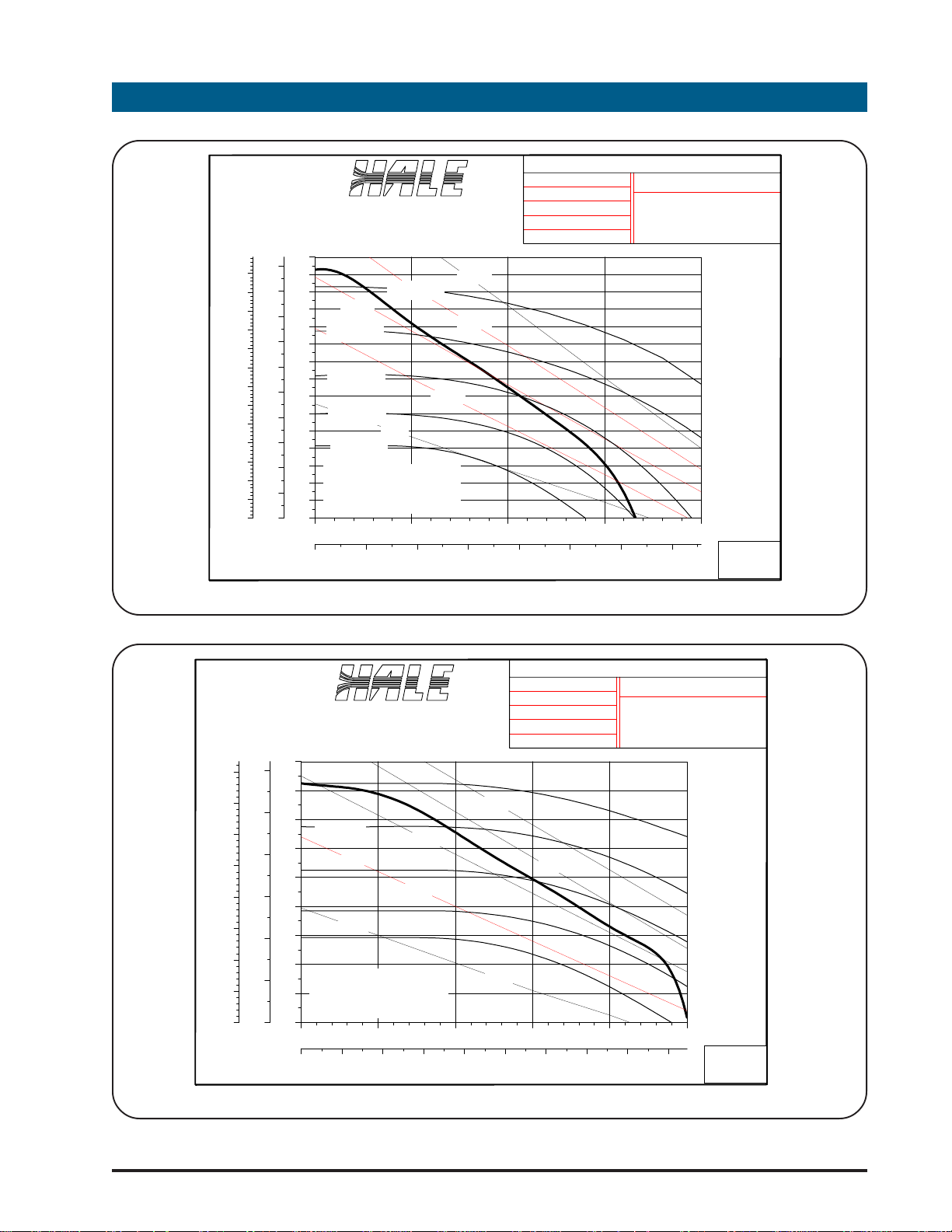
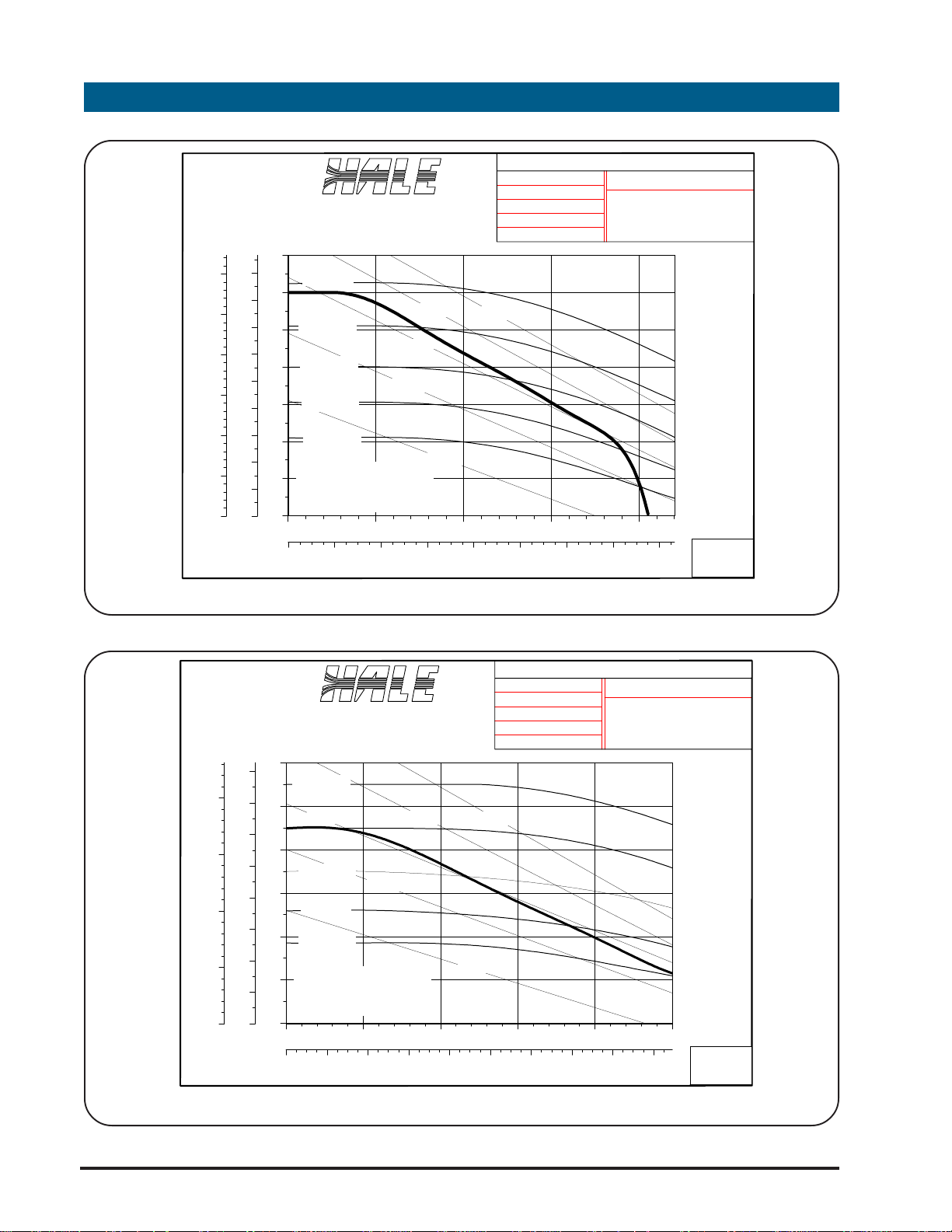
The HP series pump line has been
designed to meet stringent
requirements. The curves that follow are
the expected performance that can be
obtained from that specific pump
model. All the tests were conducted at
sea level.
NOTICE
Performance of HP Series pumps
meets or exceeds NFPA1921
requirements. For complete NFPA1921
compliance, the pumping units must be
marked with specific labels. Consult
factory if these labels are required.
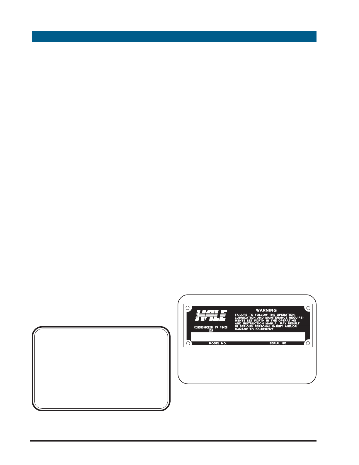
The serial number of each pump
assembly is located on a tag attached
to the engine shroud near the recoil
starter pull handle. The following figure
shows the serial number tag.
HALE PRODUCTS, INC
PUMP IDENTIFICATION TAG
10
Page 11
HP SERIES
PORTABLE PUMPS
USER OPERATION AND MAINTENANCE
20
650
18
600
550
16
500
14
450
12
400
350
10
300
8
250
6
200
150
4
100
2
50
0
0
FEET
BAR
TOTAL HEAD
Hale Fire Pump Company
Hale Products, Inc.
INLET: 2 IN
OUTLET: 1-1/ 2 IN
LIFT: 4 FT
ELEVATION: SEA-LEVEL
CONDITIONS: STP
UNIT MODEL : HP100
ENGINE:
BRIGGS & STRATTON MODEL
VANGUARD 18 OHV
300
280
260
240
220
200
3600 RPM
15 HP
3200 RPM
25 HP
20 HP
180
160
2800 RPM
140
120
2400 RPM
100
80
2000 RPM
60
PERFORMANCE BASED ON
40
95% OF ENGINE
MANUFACTURER'S MAXIMUM
20
BRAKE HORSEPOWER
0
0 50 100 150 200
PSI
5 HP
GPM
0 100 200 300 400 500 600 700
LITERS/MIN
10 HP
FLOW
HP100 SERIES PERFORMANCE CURVE
Conshohocken, Pa. 19428 USA
18 HP @ 4000 RPM
CURVE NO.
1-12-94 JDR
E-1121
180
12
400
160
350
10
140
300
250
200
150
120
8
100
6
4
100
2
50
0
0
FEET
BAR
TOTAL HEAD
4000 RPM
Hale Fire Pump Company
Hale Products, Inc.
INLET: 2-1/2 IN
OUTLET: 2-1/2 IN
LIFT: 4 FT
ELEVATION: SEA-LEVEL
CONDITIONS: STP
Conshohocken, Pa. 19428 USA
UNIT MODEL : HP200
ENGINE:
BRIGGS & STRATTON MODEL
VANGUARD 18 OHV
18 HP @ 4000 RPM
25 HP
80
60
3600 RPM
3200 RPM
2800 RPM
2400 RPM
15 HP
20 HP
10 HP
40
PERFORMANCE BASED ON
95% OF ENGINE
20
MANUFACTURER'S MAXIMUM
BRAKE HORSEPOWER
0
0 50 100 150 200 250
GPM
PSI
0 100 200 300 400 500 600 700 800 900
LITERS/MIN
5 HP
FLOW
HP200 SERIES PERFORMANCE CURVE
1-12-94 JDR
CURVE NO.
E-1122
11
Page 12
HP SERIES
PORTABLE PUMPS
USER OPERATION AND MAINTENANCE
9
300
8
250
7
6
200
5
150
4
3
100
2
50
1
0
0
FEET
BAR
TOTAL HEAD
Hale Fire Pump Company
Hale Products, Inc.
INLET: 3 IN
OUTLET: 2-1/2 IN
LIFT: 4 FT
ELEVATION: SEA-LEVEL
CONDITIONS: STP
UNIT MODEL : HP300
ENGINE:
BRIGGS & STRATTON MODEL
VANGUARD 18 OHV
140
4000 RPM
120
100
20 HP
3600 RPM
25 HP
15 HP
80
3200 RPM
10 HP
60
2800 RPM
40
2400 RPM
PERFORMANCE BASED ON
20
95% OF ENGINE
MANUFACTURER'S MAXIMUM
BRAKE HORSEPOWER
0
0 100 200 300 400
GPM
PSI
0 200 400 600 800 1,000 1,200 1,400 1,600
LITERS/MIN
5 HP
FLOW
HP300 SERIES PERFORMANCE CURVE
Conshohocken, Pa. 19428 USA
18 HP @ 4000 RPM
CURVE NO.
1-12-94 JDR
E-1123
200
150
100
50
FEET
Hale Fire Pump Company
Hale Products, Inc.
INLET: 4 IN
OUTLET: 3 IN
LIFT: 4 FT
ELEVATION: SEA-LEVEL
CONDITIONS: STP
120
8
7
6
5
4
3
2
1
0
0
BAR
4000 RPM
100
15 HP
3600 RPM
80
3200 RPM
60
2800 RPM
40
2400 RPM
PERFORMANCE BASED ON
20
95% OF ENGINE
MANUFACTURER'S MAXIMUM
BRAKE HORSEPOWER
10 HP
20 HP
25 HP
5 HP
0
0 100 200 300 400 500
GPM
PSI
0 200 400 600 800 1,000 1,200 1,400 1,600 1,800
LITERS/MIN
FLOW
Conshohocken, Pa. 19428 USA
UNIT MODEL : HP400
ENGINE:
BRIGGS & STRATTON MODEL
VANGUARD 18 OHV
18 HP @ 4000 RPM
CURVE NO.
6-21-94 JDRTOTAL HEAD
E-1124
HP400 SERIES PERFORMANCE CURVE
12
Page 13

HP SERIES
PORTABLE PUMPS
USER OPERATION AND MAINTENANCE
PUMP MODEL 100 200 300 400
TYPE
SUCTION CONNECTION
(Note 1)
HP PORTABLE
HP "X" SERIES
BODY
IMPELLER
MATERIAL
DIAMETER
SHAFT
BEARING
PRIMING
MAXIMUM FLOW AT
RATED PRESSURE
MAXIMUM PRESSURE,
BAR (PSI)
ATTACK COMBINATION SUPPLY TRANSFER
2 inch NPT Female
DISCHARGE CONNECTION (Note 1)
2 in. ISO Female 2-1/2 in. ISO Female 2-1/2 in. ISO Female 2-1/2 in.ISO Female
1-1/2 in. NPT Female
ALUMINUM ALUMINUM ALUMINUM ALUMINUM
SILICON BRONZE SILICON BRONZE SILICON BRONZE SILICON BRONZE
123.83 mm (4.875 in.) 222.25 mm (8.75 in.) 203.20 mm (8.00 in.) 184.15 mm (7.25 in.)
STAINLESS STEEL
BALL N/A N/A N/A
EXHAUST VENTURI EXHAUST VENTURI EXHAUST VENTURI EXHAUST VENTURI
568LPM @ 3.5BAR
150 GPM @ 50 PSI
20 BAR (290 PSI) 11 BAR (165 PSI) 8 BAR (120 PSI) 6 BAR (90 PSI)
3 inch NPT Female
(4 inch Victaulic)
2-1/2 in. NPT Female
(Hale 115 Flange)
ENGINE SHAFT WITH
BRONZE SLEEVE
852LPM @ 3.5BAR
225 GPM @ 50 PSI
3 inch NPT Female
(4 inch Victaulic)
3 in. NPT Female
(Hale 115 Flange)
ENGINE SHAFT WITH
BRONZE SLEEVE
1514LPM @1.4BAR
400 GPM @ 20 PSI
3 inch NPT Female
(4 inch Victaulic)
3 in. NPT Female
(Hale 115 Flange)
ENGINE SHAFT WITH
BRONZE SLEEVE
1893LPM @ 1.4BAR
500 GPM @ 20 PSI
LENGTH
WIDTH
HEIGHT
WEIGHT
LENGTH
Handles Extended
Handles Folded
WIDTH
Handles Extended
Handles Folded
HEIGHT
WEIGHT
"X" SERIES
635 mm (25 in.) 635 mm (25 in.) 635 mm (25 in.) 635 mm (25 in.)
438 mm (17-1/4 in.) 438 mm (17-1/4 in.) 438 mm (17-1/4 in.) 438 mm (17-1/4 in.)
543 mm (21-1/4 in.) 543 mm (21-1/4 in.) 543 mm (21-1/4 in.) 543 mm (21-1/4 in.)
75 kg (165 Lbs) 66 kg (146 Lbs) 67 kg (148 Lbs) 67 kg (148 Lbs)
PORTABLE SERIES
892 mm (35-1/8 in.) 892 mm (35-1/8 in.) 892 mm (35-1/8 in.) 892 mm (35-1/8 in.)
635 mm (25 in.) 635 mm (25 in.) 635 mm (25 in.) 635 mm (25 in.)
698.5 mm (27-1/2 in.) 698.5 mm (27-1/2 in.) 698.5 mm (27-1/2 in.) 698.5 mm (27-1/2 in.)
498.5 mm (19-5/8 in.) 498.5 mm (19-5/8 in.) 498.5 mm (19-5/8 in.) 498.5 mm (19-5/8 in.)
587 mm (23-1/8 in.) 587 mm (23-1/8 in.) 587 mm (23-1/8 in.) 587 mm (23-1/8 in.)
88 Kg (194 Lbs) 80 Kg (176 Lbs) 80 Kg (176 Lbs) 84 Kg (185 Lbs)
Note 1: Standard threads machined into the pump body and valve for the particular model. When ordering
pump specify suction and discharge adapter required for specific needs. With the exception of Storz adapters,
the adapters will be factory installed prior to pump delivery
13
Page 14

HP SERIES
PORTABLE PUMPS
USER OPERATION AND MAINTENANCE
3
Most of the controls and indicators
necessary for the operation of the pump
are located on the operator panel.
The pump operator should become
thoroughly familiar with the location and
function of all pump controls and
indicators before attempting operation
of the pump.
The "I" version uses engine mounted
controls that are explained in the
enclosed Briggs and Stratton engine
manual.
The controls and indicators along with
their functions are as follows:
OPERATING CONTROL DESCRIPTION
2. MASTER SWITCH: The Master
switch is located below the start
button and is used to close the
electrical circuits on the pump to
enable operation. This is a rocker
type switch which when the (
is depressed energizes the electrical
system to enable pump operation.
When the (—)side is depressed the
electrical system is disconnected and
the pump stops.
3. ST ART BUTTON ( ): The start
button is located to the right of the
❍❍
❍) side
❍❍
1. THROTTLE LEVER: The throttle lever
is located on the left side of the
instrument panel and controls the
speed at which the pump operates
to obtain the required flow. The lever
is a slide type "T"-handle that is
infinitely adjustable from SLOW
( ) to F AST ( ).
OPERATING PANEL
throttle lever and is used to start the
engine. Depressing the button after
the master switch is placed in the on
(—) position will engage the electric
starter on the pump engine. After
the button is released the button will
return to the normal position to
disengage the starter.
4. PRIMING LEVER ( ): The
Priming Lever is a "T" type
handle located to the right of
the start switch and master
switch and is used to engage
the exhaust primer when the
pump is started. Pulling the "T"
handle down will engage the
primer. Due to spring force
14
Page 15

HP SERIES
PORTABLE PUMPS
USER OPERATION AND MAINTENANCE
the handle must be held in the down
position until the pump is primed.
Once the pump is primed and
pressure is showing on the discharge
pressure gauge the "T" handle is
released and returns to the up
position by spring force for normal
pump operation.
The base "I" version uses a knob
(located above the throttle control)
which is pulled to engage the primer.
5. SUCTION GAUGE: The suction
gauge is located in the center of the
instrument panel and provides the
operator with an indication of the
water pressure on the suction side of
0.2-0.4 kg/cm2 (4-6 PSIG). If the light
should light during normal operation
the operator must shutdown the
engine immediately to avoid engine
damage.
7. CHOKE CONTROL ( ): The choke
control is located below the oil light
and is used to control the air fuel
mixture in the carburetor when
starting the engine. Pulling the choke
control out will engage the choke.
After the pump starts pushing in on
the choke control will gradually
disengage the choke and allow
normal operation.
the pump. The suction gauge is a
compound gauge that reads from -1
to 10 BAR (30 in. Hg vac to 150 PSIG).
6. LOW OIL PRESSURE LIGHT ( ):
The low oil pressure light is located to
the right of the discharge gauge and
is connected to the oil pressure
switch located on the oil filter
adapter. When the master switch is
first energized the low oil pressure
light will light to indicate the pump
power is on. After the pump starts
and oil pressure builds up the light will
go out to indicate there is sufficient
oil pressure in the engine. The engine
is equipped with an oil pressure
switch that activates the low oil
pressure light when pressure drops to
8. DISCHARGE GAUGE: The
discharge gauge is located to the
right of the priming lever and
provides the operator with an
indication of the pump discharge
pressure. The gauge reads from 0 to
28 BAR (0 to 400 PSIG).
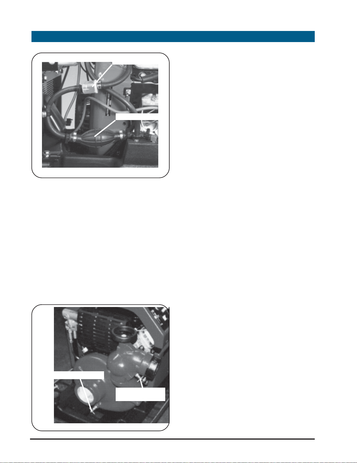
9. FUEL PRIMER: The fuel primer is
located on the back side of the
pump engine behind the protective
cover of the HP series pumps. The
fuel system requires priming only
when starting the pump after fuel is
put into the tank initially or if the
pump has run out of fuel. Priming is
accomplished by squeezing the fuel
primer bulb until firm.
15
Page 16
HP SERIES
PORTABLE PUMPS
USER OPERATION AND MAINTENANCE
FUEL FILTER
FUEL PRIMER BULB
10. RECOIL ST ARTER: The recoil starter
is located on the engine behind the
protective grill. To gain access to the
recoil starter the pump panel below
at the lowest point of the pump
volute. This valve is used to drain all
water from the pump after use and
prior to storage.
12. DISCHARGE V AL VE DRAIN: The
discharge valve drain is a petcock
type valve located below the outlet
of the discharge valve. This valve is
used to relieve the pressure in the
discharge hose before disconnecting
the hose.
13. LIGHT AND CHARGING SOCKET :
An optional marine grade light and
charging socket is located on the top
cover of the HP series portable
the instrument panel must be
opened on the portable models.
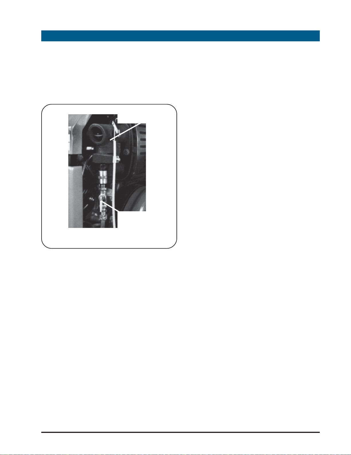
11. PUMP DRAIN: The pump drain is a
petcock type valve located below
the suction connection of the pump
PUMP DRAIN PETCOCK
DISCHARGE VALVE
DRAIN PETCOCK
pumps. This socket has a waterproof
plug type cover that is removed to
enable use of the optional light mast
(Hale P/N 200-2100-02-0). The socket
is also used to plug in the optional
trickle charger (Hale P/N 200-0750-01-
0) to maintain the charge on the
pump's 12 volt battery.
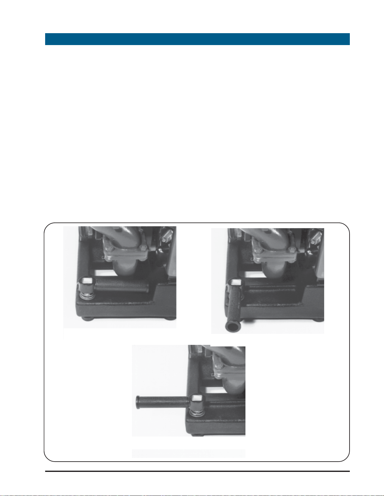
14. EXHAUST PRIMER ASSEMBL Y : The
exhaust primer assembly is located
on the outlet of the muffler. Located
on the exhaust primer assembly is a
1/4 turn valve. Under normal
operation conditions, when the
pump is being operated from draft,
the handle on the 1/4 turn valve will
16
be in the open position (in-line with
the tubing). When the pump is being
Page 17
operated with a positive pressure
source the valve must be closed to
prevent water from being blown out
of the exhaust pipe.
EXHAUST PRIMER
VALVE ASSEMBLY
HP SERIES
PORTABLE PUMPS
USER OPERATION AND MAINTENANCE
1/4 TURN BALL VALVE
(SHOWN IN NORMAL
OPERATING POSITION)
EXHAUST PRIMER ASSEMBLY
17
Page 18
HP SERIES
PORTABLE PUMPS
USER OPERATION AND MAINTENANCE
4
Upon receipt of the pump from the
factory remove the pump and all
accessories from the shipping container
and check for damage. Note the serial
number of the pump located on the
engine air shroud near the recoil starter
pull handle. Record this number on the
warranty registration card located at
the back of this manual and return
warranty registration.
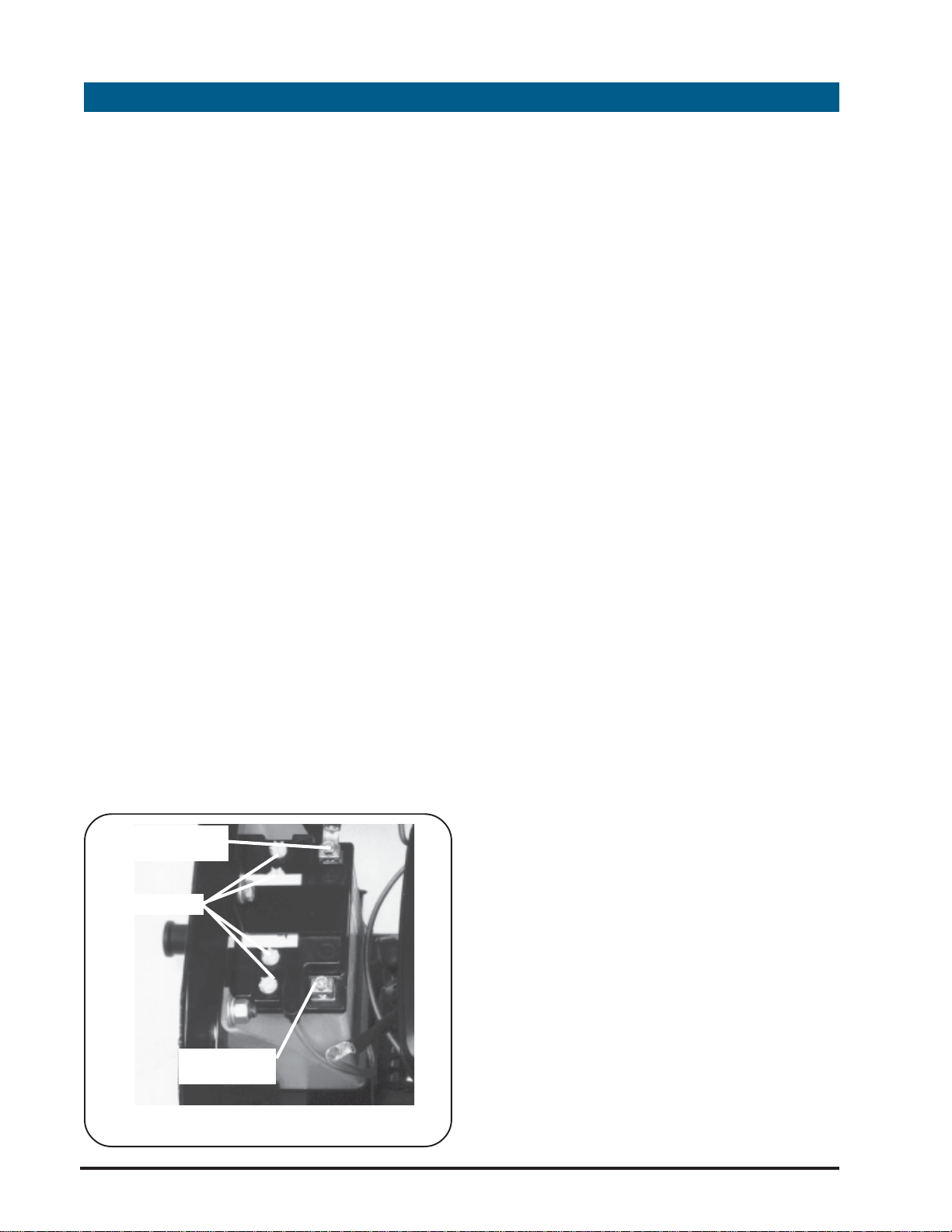
PORT ABLE PUMP BATTER Y ACTIV ATION
After unpacking all pump components
open the top cover on the pump and
remove the battery from its holder. The
battery is a dry charged battery and is
shipped dry. Remove the covers from
each cell of the battery and fill each
cell with electrolyte. Replace the covers
on each cell and tighten. Return the
INITIAL CHECKOUT PROCEDURES
battery to its holder and clamp in place.
CAUTION: Always connect
the black wire to the negative
battery terminal last.
Connect the red cable to the positive
(+) terminal and connect the black
cable to the negative (-) terminal.
Make sure that the plastic overflow tube
on the battery is directed down to the
lowest point of the pump.
"X" SERIES PUMP INST ALLATION
1. After unpacking all pump
components remove the mounting bolts
and shock absorbing feet from the four
corners of the pump. Retain these bolts
and feet for securing the pump during
installation.
18
POS BATTERY
TERMINAL
CELL CAPS
NEG BATTERY
TERMINAL
PORTABLE PUMP BATTERY
2. To assist in pump mounting a
mounting dimension drawing is included
at the back of this manual. Mark
location of the mounting holes in
accordance with this drawing.
3. Drill 9.5 mm (3/8 inch) diameter holes
at the four corners of the pump to insert
the bolts to hold the pump in place.
Place pump at proper location on the
apparatus making sure the shock
absorbing feet are under each corner.
Page 19
HP SERIES
PORTABLE PUMPS
USER OPERATION AND MAINTENANCE
Insert the bolts and secure in place with
lockwashers and nuts provided.
4. When the pump is mounted and if
access is not provided to fill the fuel tank
install optional fill tube and vent
extension as required.
NOTE: The fuel tank on the HP
series pump is already vented,
therefore a vented fuel cap is
not required
5. Locate and install the instrument
panel on the apparatus. A dimensional
drawing is provided of the instrument
panel to locate the mounting holes.
(NOTE: Approximately 2 meters (6 feet)
of wire and control cables is provided
with the pump. When locating the
instrument panel the installer must take
this into account.) Make electrical
connection from the instrument panel to
the pump with the jumper wires
provided.
isolated. When making the
permanent connections to the
suction and discharge fittings
DO NOT use hard piping. A
short length of flexible piping is
required to prevent damage
to the pump and engine.
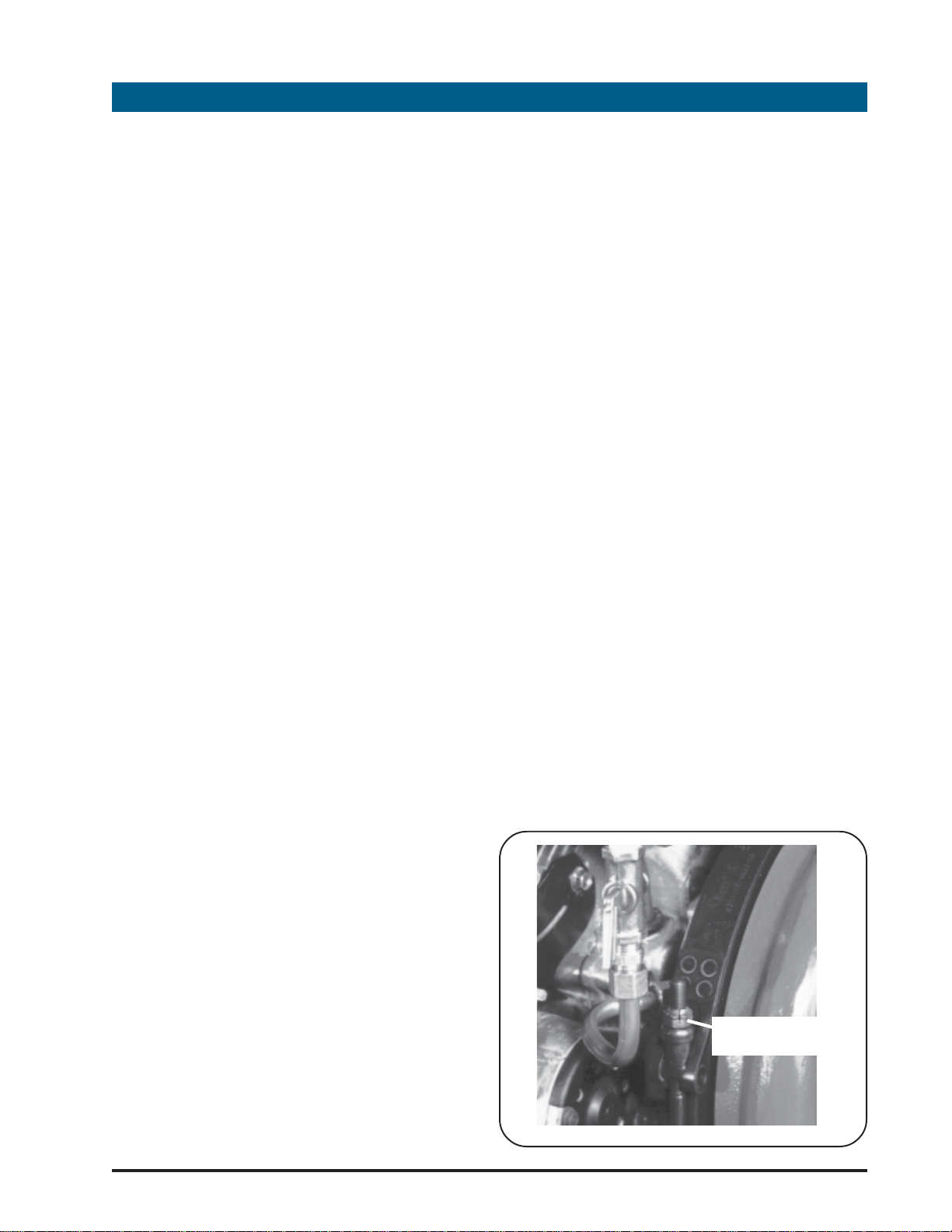
7. Make piping connections to the
discharge flange as required. When
making the piping connections it may
be necessary to turn the pump volute
for proper alignment. To turn the pump
volute:
a. Loosen and remove the "V"-band
clamp using a 1/2 inch or 13 mm
deep well socket.
b. Remove the volute from the
pump body.
c. Locate and remove the
positioning roll pin from the pump
body.
d. Return the volute to the pump
body and install "V"-band clamp.
e. Turn the volute as necessary when
6. Connect throttle lever and choke
control to the engine. Secure in place
with the clamps provided. After the
connections are made ensure the
controls work smoothly. There may be
excess cable after the connections are
made. Make a loose coil of the cable
and secure in place with wire ties.
CAUTION: The pump and
motor assembly are vibration
V-BAND CLAMP
TIGHTENING NUT
19
Page 20
HP SERIES
PORTABLE PUMPS
USER OPERATION AND MAINTENANCE
making discharge piping connection.
f. After the discharge connection is
complete tighten the "V"-band
clamp to prevent leakage.
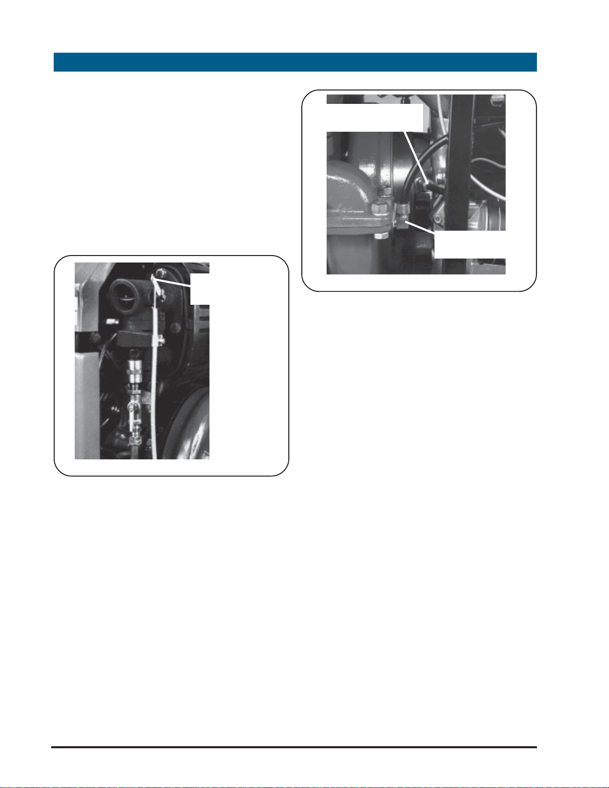
8. Connect the exhaust priming lever
cable to the exhaust primer.
EXHAUST PRIMER
CABLE
CONNECTION
SUCTION GAUGE
TUBING CONNECTION
DISCHARGE GAUGE
TUBING CONNECTION
suction fitting as required. When making
9. Connect tubing for the suction and
discharge gauges. Use the 1/4 inch
diameter tubing provided with the
pump for gauge connections. If a
longer length of tubing is required use 1/
4 inch diameter tubing rated at the
maximum operating pressure of the
pump. Connections to the gauges and
this connection ensure there are a
minimum of restrictions such as elbows
and couplings. Also, to protect the
pump from debris a strainer shall be
installed in the suction connection.
CAUTION: Always connect
the black wire to the negative
battery terminal last.
11. Connect the pump electrical system
to a 12 volt battery to provide power to
start the pump. Always connect the
positive battery cable first.
NOTE: The pump may be
connected to the apparatus
battery or a separate battery
may be used.
pump are compression type. Make sure
the gauge lines are connected to the
proper connection on the pump body.
10. Make piping connection to the
20
INITIAL OPERA TION CHECKOUT
After activating the battery on the
portable pump, or installing the "X" series
pump, prior to placing the pump into
Page 21
operation the following items must be
checked.
WARNING: DO NOT smoke
when filling fuel tank.
HP SERIES
PORTABLE PUMPS
USER OPERATION AND MAINTENANCE
WARNING: DO NOT fill fuel
tank while engine is running.
Allow engine to cool for two
minutes before refueling.
WARNING: DO NOT operate
engine when an odor of
gasoline is present or other
explosive conditions exist
WARNING: DO NOT STORE,
SPILL, OR USE GASOLINE NEAR
AN OPEN FLAME, or devices
such as a stove, furnace, or
water heater which utilize a
pilot light or devices which
can create a spark.
WARNING: DO NOT refuel
indoors where area is not well
ventilated. Outdoor refueling
is preferred.
1. CHECK FUEL LEVEL: Remove fuel filler
cap to check fuel level. Fill tank as
FUEL FILLER CAP
gasoline. The engine will
operate satisfactorily on any
gasoline intended for
automotive use. A minimum
of 85 octane is
recommended. DO NOT MIX
OIL WITH GASOLINE. Leaded
gasoline may be used if leadfree is not available.
NOTE: The use of gasoline
which contains alcohol, such
as gasohol is not
recommended. If gasoline
with alcohol must be used, it
MUST NOT contain more than
10 percent Methanol and
MUST be removed from the
engine during storage.
necessary and replace cap. DO NOT fill
the fuel tank to the point of overflowing.
The tank is designed to provide sufficient
expansion space when the tank is full.
When refilling the fuel tank ensure the
pump is level to prevent overfilling or
fuel being spilled on the ground.
FUEL RECOMMENDA TIONS: Use
clean, fresh, lead-free
2. PRIME FUEL SYSTEM: When initially
placing the pump into operation gain
access to the fuel primer bulb, located
behind the pump cover on the portable
pump, and squeeze until firm. Replace
cover after fuel system is primed.
CAUTION: The pump is
shipped without oil in the
21
Page 22
HP SERIES
PORTABLE PUMPS
USER OPERATION AND MAINTENANCE
engine crankcase. Before
placing pump into operation
for the first time fill engine
crankcase to proper level with
SAE 30 Weight Detergent oil.
3. FILL ENGINE WITH OIL: When received
the engine crankcase doesnot contain
oil. Remove oil dipstick or cap on valve
cover and fill with 3.5 pints of SAE 30 Oil.
Check oil level by removing the oil
dipstick and wiping oil from dipstick with
clean cloth. Screw dipstick firmly into
place until cap bottoms on tube.
Remove to check oil level. If necessary
add additional oil to bring oil up to the
proper level. Dipstick assembly must be
firmly assembled into tube when engine
is operating .
pump into operation for the
first time fill gearbox to proper
level with SAE 30 Weight
Detergent oil.
4. FILL HP100 GEAR BOX WITH OIL: The
HP100 is shipped without oil in the gear
box. Add oil to proper level in
accordance with procedures listed in
section 8. Replace oil level plug.
5. CONNECT SUCTION HOSE: Ensure the
hose connections are tightened with a
spanner and a strainer is placed at the
end of the hose to prevent debris from
entering the pump and causing
irreparable damage. Place end of
suction hose in water source. Make sure
the end of the suction hose does not
CAUTION: The HP100 is
shipped without oil in the
gearbox. Before placing
OIL FILL CAP
become submerged in the mud or silt on
the bottom. Also make sure the suction
hose has no bends or loops that are
higher than the suction connection of
the pump that would trap air and
prevent priming of the pump.
OIL FILL FITTING
OIL LEVEL PLUG
OIL DIPSTICK
OIL DRAIN PLUG
22
Page 23

6. CONNECT DISCHARGE HOSE: After
connecting discharge hose ensure the
discharge valve is closed. Remove all
kinks and sharp bends from the
discharge hose.
7. CLOSE PUMP DRAINS: Make sure the
pump and discharge valve drains are
closed.
HP SERIES
PORTABLE PUMPS
USER OPERATION AND MAINTENANCE
SUCTION HOSE
CONNECTION
DISCHARGE
VALVE
23
Page 24

HP SERIES
PORTABLE PUMPS
USER OPERATION AND MAINTENANCE
5
The following procedures will be
followed to start the pump and establish
water flow.
WARNING: DO NOT run engine
in an enclosed area. Exhaust
gases contain carbon
monoxide, an odorless and
deadly poison.
WARNING: Engine produces
excessive noise. When pump
is operating persons in the
immediate vicinity must wear
hearing protection.
1. CLOSE VAL VES: Make sure all pump
drains and discharge valves are closed
2. SET THROTTLE LEVER: Move throttle
lever upward to fast ( ) position.
3. CHOKE ENGINE: Pull choke knob
STARTING PROCEDURES
indicates the battery is good and the
pump is ready to start. If the oil light is
not lit check the battery connections
and ground connections. It may be
necessary to start the pump using the
recoil starter if the oil light does not light.
5. ST ART ENGINE: Depress start push
button ( ) and hold until engine starts.
When engine starts, open choke
gradually by pressing in on choke knob.
NOTE: The best starter life is
provided by using short
starting cycles of several
seconds. Prolonged cranking
(more than 15 seconds per
minute) can damage the
starter motor. If the engine
does not start in 15 seconds
release starter button. Allow
starter to cool two minutes.
( ) out fully to close choke on
carburetor.
NOTE: A warm engine requires
less choking than a cold
engine. When starting a warm
engine little or no choke will
be required.
4. ENERGIZE ELECTRICAL SYSTEM: Place
Master Switch to the ON (—) position.
Check to make sure oil light is lit. This
24
If the engine does not start using the
electric starter, the recoil starter must be
used.
a. Open pump cover on instrument
panel side of the pump if applicable.
b. Locate recoil starter handle and
pull slowly until resistance is felt then
pull rapidly to overcome
compression, prevent kickback and
start engine.
c. Once the engine starts open
choke gradually by pressing in on
choke knob.
Page 25

HP SERIES
PORTABLE PUMPS
USER OPERATION AND MAINTENANCE
to obtain the desired discharge pressure
For the "I" version, turn the key switch
and release when the pump has started.
6. PRIME PUMP: Hold priming lever ( )
down to prime the pump and establish
suction. Monitor suction and discharge
gauges to determine when suction is
established. Once suction is established
release the priming lever and make sure
the lever returns to the up position.
CAUTION: Do not run pump
for more than 45 seconds
without suction established.
NOTE: When the pump is
connected to a positive
pressure source priming is not
required. When using the
pump with a positive pressure
connected to the inlet ensure
the 1/4 turn valve on the
exhaust primer assembly is in
the closed position prior to
starting the pump.
on the discharge gauge.
CAUTION: Exhaust system
components may smoke
during the initial break-in
period. This smoking will stop
after the pump is run several
times.
COLD WEA THER STARTING HINTS
1. Be sure to use the proper oil for the
temperature expected.
2. Set speed control at part-throttle
position.
3. A warm battery has much more
starting capacity than a cold battery.
4. Use fresh winter grade fuel.
NOTE: Winter grade gasoline
7. EST ABLISH DISCHARGE: Once suction
is established as indicated by the
gauges, open the pump discharge
valve by rotating handle
counterclockwise.
8. ADJUST THROTTLE: Adjust throttle lever
25
Page 26

HP SERIES
PORTABLE PUMPS
USER OPERATION AND MAINTENANCE
6
To enhance pump life the following
procedures shall be used when shutting
down the pump.
1. SLOW ENGINE: Move throttle lever to
the slow ( ) position.
2. SECURE DISCHARGE: Close pump
discharge valve by rotating handle
clockwise.
3. SECURE ELECTRICAL POWER: Turn
master switch to the off (
SHUTDOWN AND STORAGE PROCEDURES
) position.
NOTE: Do not choke
carburetor to stop the engine.
Fire may result if choke is used
to stop engine.
2. ENERGIZE PUMP: Start engine and
establish water flow through pump.
3. FLUSH PUMP: Run pump for 2 minutes
to ensure clean water has circulated
through the pump.
4. DE-ENERGIZE PUMP: After water has
circulated through the pump for 2
minutes turn the master switch to the off
position.
5. UNDO HOSE CONNECTIONS:
Disconnect suction hose and discharge
hose. Drain hoses and place in proper
storage area
6. DRAIN PUMP: Open drain valves and
Prior to placing the pump in storage
after each use the following must be
accomplished. This procedure is
extremely important if the pump has
been run in salt water or freezing
conditions will be encountered.
1. MAKE HOSE CONNECTIONS: Connect
suction hose and place end in a CLEAN
WATER source. Then connect discharge
hose and prepare to operate pump.
26
allow all water to drain from the pump
body.
7. CLOSE V A LVES: Once all water is
drained from the pump close the
discharge valve and drain valve.
8. CHECK FLUID LEVELS: Check oil level
and fuel level and refill as necessary.
9. CLEAN PUMP: Clean any debris from
the outside of the engine and pump.
Page 27

Also, wipe the pump covers down with a
clean damp cloth. If necessary use a
mild soap and water solution to clean
plastic covers.
10. STORE PUMP: Return pump to
storage compartment and secure in
place.
HP SERIES
PORTABLE PUMPS
USER OPERATION AND MAINTENANCE
27
Page 28

HP SERIES
PORTABLE PUMPS
USER OPERATION AND MAINTENANCE
7
MAINTENANCE SCHEDULE
MAINTENANCE INTERVALS
To prolong pump life and ensure reliable operation the pump user shall perform the
maintenance described in the following section on a regular basis. The table that
follows provides a listing of the minimum maintenance intervals. Following the chart
are detailed maintenance procedures.
MAINTENANCE OPERATION
Check Oil Level
Change Oil † (NOTE 1)
Change Oil Filter
Clean Foam Air Cleaner
Pre-Cleaner (NOTE 2)
Service Air Cleaner Cartridge
(NOTE 2)
Every 8
Hours or
Daily
ENGINE MAINTENANCE
●
25 Hours or
Weekly
●
50 Hours
or Monthly
●
100 Hours
or Yearly
●
●
Yearly
Clean Cooling System (NOTE 2)
Clean Debris Gard (NOTE 2)
Inspect Spark Arrester
Replace In-Line Fuel Filter
Replace Spark Plug
Check Valve Clearance
Check Oil Level (NOTE 3)
Change Gear Oil (NOTE 3)
Leak Test
† : Change oil after first 8 hours.
NOTE 1: Change oil every 25 hours when operating under heavy load or in high ambient temperature.
NOTE 2: Clean more often under dusty conditions or when airborne debris is present.
NOTE 3: HP100 Model Pump Only.
●
PUMP MAINTENANCE
●
●
●
●
●
●
●
●
28
Page 29

HP SERIES
PORTABLE PUMPS
USER OPERATION AND MAINTENANCE
8
The HP Series portable pumps are
designed to provide years of reliable
service with a minimum of maintenance
on the pump end. The pump must be
cleaned and flushed out after each use.
Failure to clean and flush the pump may
degrade pump performance. The only
maintenance that is usually required on
a regular basis is to hydrostatically test
the pump each year.
LEAK TEST
A leak test of the pump must be
performed each year. The leak test will
be conducted at the pump working
PUMP MAINTENANCE
OIL FILL FITTING
OIL LEVEL PLUG
OIL DRAIN PLUG
1. Place pump on a level work
surface to gain access to the
gearbox.
pressure.
WARNING: T O PREVENT
ACCIDENT AL ST ARTING when
servicing the engine or pump
always disconnect the
negative wire from battery
terminal.
CHECK OIL LEVEL (HP100 GEARBOX)
The HP100 pump has a gearbox that
requires routine maintenance. The oil
should be checked in the gearbox every
eight hours of operation and after each
use of the pump. The following
procedures are used to check the oil
level in the HP100 gearbox.
2. Locate the oil fill fitting, the oil level
plug and the oil drain plug on the
pump gearbox.
3. Loosen oil level plug with wrench
and begin to remove slowly. If the oil
is at the proper level there should be
a slight trickle of oil from around the
plug.
4. Replace plug and tighten. If oil
needs refilling remove oil fill fitting,
vent and oil level plug. Add new
gear oil (SAE 30) through oil fill fitting
until oil starts to flow from oil level
plug. Replace and tighten oil level
plug.
29
Page 30

HP SERIES
PORTABLE PUMPS
USER OPERATION AND MAINTENANCE
5. Replace oil fill fitting and vent.
6. Return pump to storage or
operation.
CHANGE GEARBOX OIL (HP100)
The oil in the gearbox of the HP100
should be changed after every 50 hours
of operation. The following procedures
shall be used to change the gearbox oil.
1. Place pump on clean level work
surface and gain access to the
pump gearbox.
2. Place container under oil drain
6. Remove oil level plug from
gearbox.
7. Place funnel in oil fill fitting and
slowly pour oil into gearbox until oil
starts to flow from the oil level hole.
8. Replace oil level plug, oil fill fitting
and vent.
9. Return pump to storage or
operation.
EXHAUST PRIMER MAINTENANCE
The exhaust primer should be cleaned
after every 100 hours of operation or
plug to catch waste oil.
3. Using a wrench remove oil drain
plug.
NOTE: The oil may not flow
freely from the gear case at
first. To facilitate oil flow
remove oil fill fitting.
4. Replace oil drain plug after all oil
has drained from the gearbox.
NOTE: Dispose of waste oil in
accordance with local
ordinances.
5. Obtain proper grade of oil (SAE
when priming of the pump appears
sluggish. The following procedures shall
be used to clean the exhaust primer.
EXHAUST PRIMER
BOLTS
EXHAUST PRIMER
CABLE
EXHAUST PRIMER
ASSEMBLY
30
30).
EXHAUST PRIMER
TUBING
Page 31

HP SERIES
PORTABLE PUMPS
USER OPERATION AND MAINTENANCE
WARNING: T O PREVENT
ACCIDENT AL ST ARTING when
servicing the engine or pump
always disconnect the
negative wire from battery
terminal.
1. Place pump on clean work
surface and gain access to the
exhaust primer.
2. Disconnect Negative battery
terminal to prevent accidental
starting of the pump.
3. Unsnap and remove the muffler
heat shield.
8. Using wire brush and tip cleaners
carefully remove carbon from ejector
nozzle and check valve assembly.
9. Insert check valve ball into ejector
body. Using a new gasket (P/N
046-0850-01-0) assemble ejector
body to exhaust valve body using
hex head screws.
10. Install exhaust valve assembly to
the muffler using new gasket (P/N
046-6240-01-0) and hex head screws.
11. Connect hoses and cables that
were disconnected back to the
4. Disconnect cable from the
actuating lever to the butterfly.
Disconnect all tubing from the
exhaust primer.
5. Remove hex head screws that
hold the exhaust valve to the muffler.
Remove the exhaust valve to a clean
work surface.
6. Place exhaust valve assembly on
bench with ejector body facing up.
Remove hex head screws and
separate the ejector body from the
exhaust valve body.
exhaust valve assembly.
12. Ensure priming lever on
instrument panel moves freely after
assembly. If lever does not move
freely the conduit or cable may be
dirty or damaged. Clean or replace
as necessary.
13. Replace the heat shield on the
muffler and snap in place.
14. Reconnect the negative battery
terminal.
15. Return pump to ready condition.
7. Remove check valve ball from
ejector body.
31
Page 32

HP SERIES
PORTABLE PUMPS
USER OPERATION AND MAINTENANCE
9
General lnformation
This is a twin cylinder, overhead valve, air cooled engine. All drilled/tapped holes
and fasteners on this engine are ISO metric. however, where equipment attaches
to engine, SAE standards apply.
CHECK OIL LEVEL
The oil level should be checked after
each 8 hours of operation. Use the
following procedure to check the oil
level:
ENGINE MAINTENANCE
WARNING: T O PREVENT
ACCIDENT AL ST ARTING when
servicing the engine or pump
always disconnect the
negative wire from battery
terminal.
1. Place pump on level surface.
2. On portable pump, undo latches
and open top cover to gain access
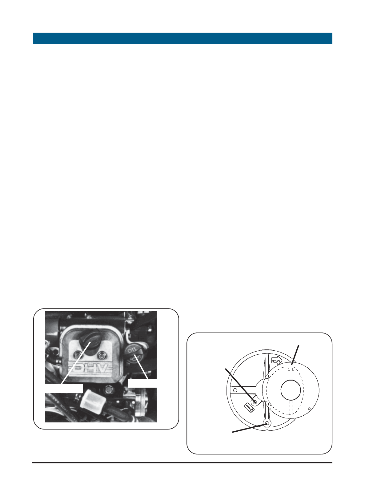
to dipstick.
7. Close pump cover and latch in
place.
CHANGE OIL
Change oil after the first 8 hours of
operation. Then, under normal
operating conditions, change oil every
50 hours of operation or monthly,
whichever occurs first.
NOTE: Oil should be changed
every 25 hours of operation if
the engine is operated under
heavy load, or in high ambient
temperatures.
3. Unscrew oil dipstick cap, remove
oil dipstick and wipe oil from dipstick.
4. Screw dipstick firmly into place
until cap bottoms on tube.
5. Unscrew oil dipstick cap, remove
oil dipstick and check oil level.
Proper oil level is when oil is visible on
the dipstick end between the "ADD"
and "FULL" marks.
6. Screw dipstick firmly into place
until cap bottoms on tube. Cap must
be tight while pump is operating.
32
When changing oil use a high quality
SAE 10W-30 or SAE 30 weight detergent
oil classified “For Service SC, SD, SE, SF or
SG”. Detergent oils keep the engine
cleaner and retard the formation of
gum and varnish deposits. No special
additives should be used with
recommended oils. The following table
provides the recommended viscosities
of oil to use based on the anticipated
operating temperature range.
Page 33

TEMPERATURE RANGE ANTICIPATED BEFORE NEXT OIL CHANGE
HP SERIES
PORTABLE PUMPS
USER OPERATION AND MAINTENANCE
3. The oil drain fitting is a hex fitting
with a pipe plug. Use adjustable
wrench to hold hex fitting while
removing the pipe plug with an allen
wrench.
4. Once all oil is drained from the
crankcase replace pipe plug in oil
drain fitting and tighten with allen
Change oil using the following
procedures:
1. Place the pump assembly in a
work area where access can be
made to the oil drain fitting. Ensure
the pump is level. Disconnect
Negative battery cable to prevent
accidental starting of the pump.
2. Place container under oil drain
fitting to catch waste oil as it drains
from the pump.
wrench.
NOTE: Dispose of waste oil in
accordance with local
ordinances.
5. Remove oil fill cap on valve cover
or dipstick and place on a clean
surface.
6. Using a funnel to prevent spills, refill
crankcase with the proper grade of
oil.
NOTE: The engine will require
a minimum of 3 pints (1.4 liters)
if the oil filter is not replaced
and 3.5 pints (1.6 liters) if the oil
filter is replaced.
OIL DRAIN FITTING
7. Check oil level and replace
dipstick or oil fill cap.
8. Reconnect negative battery
cable. Start pump and run for 30
seconds. Shut down the pump and
33
Page 34

HP SERIES
PORTABLE PUMPS
USER OPERATION AND MAINTENANCE
check oil level. Refill crankcase as
necessary.
9. Check area around pump for oil
leaks.
10. Return pump to storage area.
REPLACE OIL FIL TER
The oil filter should be replaced after
every 100 hours of pump usage or
yearly.
WARNING: T O PREVENT
ACCIDENT AL ST ARTING when
servicing the engine or pump
always disconnect the
negative wire from battery
terminal.
Replace the oil filter using the following
procedures:
1. Place the pump assembly in a
work area where access can be
made to the oil drain fitting. Ensure
the pump is level.
2. On portable pump unlatch and
remove covers to gain access to
engine. Disconnect the negative
battery cable to prevent accidental
starting.
3. Place container under oil drain
fitting to catch waste oil as it drains
from the pump.
NOTE: The engine oil should
be changed whenever the oil
filter is replaced.
OIL FILTER
4. The oil drain fitting is a hex fitting
with a pipe plug. Use adjustable
wrench to hold hex fitting while
removing the pipe plug with an allen
wrench.
5. Once all oil is drained from the
crankcase replace pipe plug in oil
drain fitting and tighten with allen
wrench.
NOTE: Dispose of waste oil in
accordance with local
ordinances.
6. Using oil filter wrench remove and
dispose of old oil filter.
34
OIL FILTER ASSEMBLY
Page 35

HP SERIES
PORTABLE PUMPS
USER OPERATION AND MAINTENANCE
NOTE: Before installing new
filter, lightly oil filter gasket with
fresh clean engine oil.
7. Oil the filter gasket and screw the
new oil filter on by hand until gasket
contacts filter adapter then tighten
an additional 1/4 to 1/2 turn.
8. Remove oil fill cap on valve cover
or oil dipstick and place on a clean
surface.
9. Using a funnel to prevent spills, refill
crankcase with the proper grade of
oil.
NOTE: The engine will require
a minimum of 3 pints (1.4 liters)
if the oil filter is not replaced
and 3.5 pints (1.6 liters) if the oil
filter is replaced.
10. Check oil level and replace
13. Check area around pump for oil
leaks.
14. Return pump to storage area.
DUAL ELEMENT AIR CLEANER
The air cleaner consists of a foam
pre-cleaner and a paper cartridge. The
foam pre-cleaner should be serviced
after every 25 hours of pump operation
or weekly. The paper cartridge should
be serviced after every 100 hours of
pump operation or yearly.
WARNING: T O PREVENT
ACCIDENT AL ST ARTING when
servicing the engine or pump
always disconnect the
negative wire from battery
terminal.
NOTE: Service air cleaner more
often when operating under
dusty conditions.
dipstick or oil fill cap.
11. Replace covers and remove
pump from work area.
12. Reconnect the negative battery
cable. Start pump and run for 30
seconds. Shut down the pump and
check oil level. Refill crankcase as
necessary.
1. On the portable pump, unlatch
and open the pump top cover to
gain access to the air cleaner.
Disconnect negative battery cable.
2. Remove air cleaner cover
assembly by releasing the latches on
either side of the cover and lift cover
off pump.
35
Page 36

HP SERIES
PORTABLE PUMPS
USER OPERATION AND MAINTENANCE
3. Remove nut holding retainer
plate, cartridge and foam pre-
cleaner to top of engine.
4. Remove retainer plate and foam
pre-cleaner from cartridge.
5. Service foam pre-cleaner:
a. Wash in liquid detergent and
water.
b. Squeeze dry in a clean cloth.
c. Saturate in engine oil. Squeeze
in clean, absorbent cloth to remove
all excess oil.
6. Service cartridge:
a. Clean by tapping gently on flat
cartridge air dry thoroughly before
using.
CAUTION: Petroleum solvents,
such as kerosene, are not to
be used to clean cartridge.
They may cause deterioration
of the cartridge. DO NOT OIL
CARTRIDGE. DO NOT USE
PRESSURIZED AIR TO CLEAN OR
DRY CARTRIDGE
AIR CLEANER COVER
surface.
b. If very dirty, replace, or wash in
a low or non-sudsing detergent and
warm water solution. Rinse
thoroughly with flowing water from
mesh side until water runs clear. Let
AIR CLEANER
COVER
NUT
RETAINER PLATE
FOAM
PRE-CLEANER
AIR CLEANER
COVER LATCH
AIR FILTER COVER REMOVAL
AIR CLEANER
HOUSING
36
CARTRIDGE
AIR FILTER COMPONENTS
Page 37

7. Reinstall pre-cleaner and retainer
ring on cartridge.
8. Reinstall foam pre-cleaner,
cartridge and retainer plate
assembly in air cleaner housing on
top of engine. Secure in place with
nut.
9. Reinstall air cleaner cover on top
of pump and latch in place.
WARNING: DO NOT run engine
with air cleaner or air cleaner
cover removed.
HP SERIES
PORTABLE PUMPS
USER OPERATION AND MAINTENANCE
10. Reconnect negative battery
cable and close pump cover as
necessary.
CLEAN COOLING SYSTEM
If the pump is operated in an area
where there is loose debris such as grass,
papers, leaves or dirt the rotating screen
and the air cooling system may become
clogged after prolonged service. After
every 100 hours of operation or yearly
remove the pump covers and blower
housing and clean the areas shown in
the illustration to prevent engine
damage caused by overheating and/or
over-speeding. Clean more often if
necessary.
CLEAN DEBRIS GUARD
If the pump is operated in a dry area
where there is loose debris such as grass,
papers, leaves or dirt this debris must be
removed from the debris guard daily or
more often if needed to prevent engine
damage caused by overheating and/or
over-speeding.
CAUTION: For proper engine
operation, keep controls and
linkages clean and free of
debris.
CAUTION: Periodically clean
muffler area to remove all
grass, paper, leaves, dirt or
other combustible debris.
CLEAN SPARK ARRESTER SCREEN
The engine muffler is equipped with a
spark arrester screen assembly. Remove
37
Page 38

HP SERIES
PORTABLE PUMPS
USER OPERATION AND MAINTENANCE
this assembly every 50 hours of pump
operation or monthly for cleaning and
inspection.
WARNING: T O PREVENT
ACCIDENT AL ST ARTING when
servicing the engine or pump
always disconnect the
negative wire from battery
terminal.
To remove the spark arrestor screen
make sure the pump and muffler are
cool and proceed as follows:
1. Remove heat shield from muffler
assembly and locate the exhaust
primer assembly.
2. Disconnect negative battery
cable to prevent accidental starting
3. Disconnect primer tubing and
primer control cable as necessary.
4. Remove the three bolts that hold
the exhaust primer assembly on the
muffler. Remove the exhaust primer
assembly.
5. Remove the spark arrestor screen
assembly from the muffler.
6. Clean the spark arrestor screen
assembly with a stiff wire brush.
7. Inspect spark arrestor screen
assembly for damage and
deterioration. If the screen is
damaged replace the screen.
of the pump.
EXHAUST PRIMER
BOLTS
EXHAUST PRIMER
ASSEMBLY
EXHAUST PRIMER
CABLE
EXHAUST PRIMER
TUBING
SPARK ARRESTOR SCREEN ACCESS
8. Install new gasket along with the
Spark arrestor screen assembly on the
muffler.
9. Install another new gasket and the
exhaust valve primer assembly.
Secure with the three bolts.
10. Connect exhaust primer control
cable and primer tubing as required.
11. Install the heat shield on the
muffler.
12. Connect negative lead to
battery.
38
Page 39

HP SERIES
PORTABLE PUMPS
USER OPERATION AND MAINTENANCE
Spark Plug Type Champion Autolite
13. Return pump to storage or
operation.
REPLACE SPARK PLUGS
Replace the spark plugs every 100 hours
of operation or yearly.
To replace the spark plugs ensure the
pump is cool and proceed as follows:
1. Unlatch and remove pump engine
covers to gain access to the pump
engine.
2. Disconnect negative battery lead.
3. Remove spark plug wire from
spark plug.
Resistor RC12YC 3924
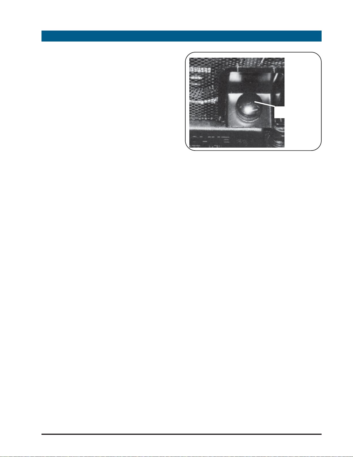
Spark Plug Gap .............. 76 mm (.030 in.)
5. Obtain new spark plug and check
gap using a wire gauge. The proper
gap is 0.030 in (0.76 mm).
SPARK PLUG GAP CHECKING
6. Insert the new spark plug into hole
4. Using spark plug wrench remove
spark plug.
NOTE: Do not blast clean
spark plug. Spark plug should
be cleaned by scraping or
wire brushing and washing
with a commercial solvent.
NOTE: In some areas, local
law requires the use of a
resistor spark plug to suppress
ignition signals. If the engine
was originally equipped with a
resistor spark plug, be sure to
use the same type of spark
plug for replacement. The
following is a list of the
recommended sparkplugs.
and screw in being careful not to
cross thread.
7. Reconnect spark plug wire to
spark plug.
CAUTION: Sparking can occur
if wire terminal does not fit
firmly on spark plug. Reform
terminal if necessary.
8. Reconnect negative battery lead.
9. Install pump covers and latch in
place.
39
Page 40

HP SERIES
PORTABLE PUMPS
USER OPERATION AND MAINTENANCE
REPLACE FUEL FILTER
A clogged or dirty fuel filter can
adversely affect engine performance.
The fuel filter should be replaced each
year or more often as engine
performance dictates. The following
procedures are to be used to replace
the fuel filter.
WARNING: T O PREVENT
ACCIDENT AL ST ARTING when
servicing the engine or pump
always disconnect the
negative wire from battery
terminal.
1. Unlatch and open (or remove)
pump covers on portable pump to
3. Using pliers remove clips holding
the fuel filter in the fuel line.
4. Place a container under the fuel
filter to catch any excess fuel that
may be in the lines.
5. Remove the fuel filter from the fuel
lines.
6. Place new clips on the fuel lines.
7. Insert the new fuel filter in the fuel
line and push fuel hoses onto
connectors.
8. Using pliers, slide clips towards the
gain access to the fuel filter.
Disconnect negative battery cable.
2. Locate fuel filter.
FUEL FILTER
HOSE CLAMPS
fuel filter to clamp hoses in place.
9. Close (or replace) pump covers
on portable pump and latch.
PORTABLE PUMP BATTERY CHECK
To ensure reliable operation of the pump
the battery must be checked annually
to ensure sufficient power is available to
start the engine. To accomplish the
battery check the following procedures
shall be used.
1. Open covers to pump, where
applicable, and locate the battery.
2. Disconnect the cables from the
40
positive and negative terminals.
FUEL FILTER REPLACEMENT
Page 41

HP SERIES
PORTABLE PUMPS
USER OPERATION AND MAINTENANCE
POS BATTERY
TERMINAL
CELL CAPS
NEG BATTERY
TERMINAL
PORTABLE PUMP BATTERY
Always remove the negative terminal
first.
4. Connect battery load test
instrument to the terminals and place
battery under simulated starting load
with the test instrument. The meter
should read 9 volts or more when the
simulated starting load is applied. If
the meter does not read 9 volts,
replace the battery.
NOTE: Dispose of used battery
in accordance with local
ordinances.
5. Reconnect the cables to the
positive and negative terminals.
Always connect the negative
terminal last.
3. Check the specific gravity of each
cell with a hydrometer. All cells
should have a specific gravity of
1.250 with no more than 0.50
variation between any two cells. If
the specific gravity is less than 1.225
or varies by more than 0.50 between
any two cells replace the battery.
6. Replace pump covers as
necessary.
7. Return pump to storage area for
operation.
41
Page 42

HP SERIES
PORTABLE PUMPS
USER OPERATION AND MAINTENANCE
10
Hale Products, Inc., herein referred to as “Hale”, warrants products of its
manufacture to be free from defects in material and workmanship, under normal
use and service, for a period of two years or 2000 hours of usage, whichever comes
first. Products used for rental or contracting purposes are warranted for a period of
six months or 2000 hours of usage, whichever comes first. This limited warranty is
effective only if the equipment or apparatus is used as directed, is not subjected to
misuse, negligence or accident, and is not altered, treated or repaired by someone
other than Hale or its designee. Items not manufactured by Hale shall bear only the
limited warranties offered by their respective manufacturers.
The exclusive remedy for breach of this warranty shall be to give Hale written notice
thereof and to request a Returned Goods Authorization. Upon receipt of the
Returned Goods Authorization, the buyer will return the non-conforming material to
Hale F.O.B. its plant within thirty days after the buyer has received the Returned
Goods Authorization. Thereupon Hale at its own election shall repair or replace the
same or repay the price thereof. No proximate, incidental, consequential or other
damages shall be recoverable.
Hale shall not be liable for consequential damages or contingent liabilities
including; but not limited to, loss of life, personal injury, loss of crops, loss due to fire
or water property damage, and consequential trade or other commercial loss
arising out of the failure of Manufacturer’s product.
WARRANTY POLICY
HALE MAKES NO WARRANTIES OF FREEDOM FROM P A TENT INFRINGEMENT , OF
MERCHANT ABILITY , OF FITNESS FOR A P ARTICULAR PURPOSE OR ARISING FROM A
COURSE OF DEALING OR USAGE OF TRADE OR OTHER LIKE OR DIFFERENT EXPRESS
OR IMPLIED WARRANTIES EXCEPT AS MADE ABOVE.
42
Page 43

HP SERIES
PORTABLE PUMPS
USER OPERATION AND MAINTENANCE
11
"X" SERIES PUMP MOUNTING DRAWINGS
The following pages contain drawings to assist in the mounting of "X" Series pumps
on apparatus. The drawings are not to scale but will assist the installer in locating
mounting holes for the pumps.
MOUNTING DIMENSIONS
"X" Series Pump Mounting Dimensions
43
Page 44

HP SERIES
PORTABLE PUMPS
USER OPERATION AND MAINTENANCE
44
"X" Series Pump Mounting Dimensions
Page 45

HP SERIES
PORTABLE PUMPS
USER OPERATION AND MAINTENANCE
"X" Series Pump Base Mounting Hole Location Dimensions
45
Page 46

HP SERIES
PORTABLE PUMPS
USER OPERATION AND MAINTENANCE
"X" Series Pump Control Panel Mounting Hole Location Dimensions
46
Page 47

HP SERIES
PORTABLE PUMPS
USER OPERATION AND MAINTENANCE
"I" SERIES PUMP MOUNTING DRAWINGS
The following pages contain drawings to assist in the installation of "I" Series pumps
on apparatus. The drawings are not to scale but will assist the installer in locating
mounting holes and determining compartment size for the pumps.
"I" Series Pump Dimensions
47
Page 48

HP SERIES
PORTABLE PUMPS
USER OPERATION AND MAINTENANCE
48
"I" Series Pump Dimensions
Page 49

HP SERIES
PORTABLE PUMPS
USER OPERATION AND MAINTENANCE
12
ELECTRICAL WIRING DIAGRAMS
HP and HP"X" Series Electrical Wiring Diagram
49
Page 50

HP SERIES
PORTABLE PUMPS
USER OPERATION AND MAINTENANCE
50
HP"I" Series Electrical Wiring Diagram
Page 51

HP SERIES
PORTABLE PUMPS
USER OPERATION AND MAINTENANCE
13
The following pages contain exploded views of the HP Portable, "X" Series and "I"
Series pumps. Each part of the pump is identified on the illustration with an index
number. Located in the list on the page next to the illustration are the Hale
Products Inc. part numbers for the component parts. When repairing the pump
refer to these exploded views to identify the part numbers of components requiring
replacement.
PARTS LIST
51
Page 52

HP SERIES
PORTABLE PUMPS
USER OPERATION AND MAINTENANCE
3
1
6
4
5
52
PL-1: HP SERIES PUMP COMPONENT IDENTIFICATION
Page 53

HP SERIES
PORTABLE PUMPS
USER OPERATION AND MAINTENANCE
PL-1: HP SERIES PUMP COMPONENT IDENTIFICATION
ITEM PART NUMBER DESCRIPTION QTY UNIT
545-4050-00-0 HP100 PORTABLE PUMP EA
545-4050-02-0 HP100X PORTABLE PUMP EA
545-4060-00-0 HP200 PORTABLE PUMP EA
545-4060-02-0 HP200X PORTABLE PUMP EA
545-4070-00-0 HP300 PORTABLE PUMP EA
545-4070-02-0 HP300X PORTABLE PUMP EA
545-4080-00-0 HP400 PORTABLE PUMP EA
545-4080-02-0 HP400X PORTABLE PUMP EA
1 HP SERIES PUMP END
(FOR DETAILS SEE: PL-3 FOR HP200,
HP300 AND HP400: PL-4 FOR HP100) 1.0 EA
2 045-0680-00-0 B&S MODEL 350447-0080 ENG (B35)
(FOR MOUNTING DETAILS SEE PL-8) 1.0 EA
3 538-1520-00-0 EXHAUST PRIMER ASSEMBLY
(FOR DETAILS SEE PL-7) 1.0 EA
4 OIL FILTER AND DRAIN
ASSEMBLY (FOR DETAILS SEE PL-11) 1.0 EA
5 503-1340-00-0 FUEL SYSTEM
(FOR DETAILS SEE PL-10) 1.0 EA
6 168-0070-13-0 HP X SERIES INSTRUMENT PANEL
ASSEMBLY (FOR DETAILS SEE PL-9) 1.0 EA
53
Page 54

HP SERIES
PORTABLE PUMPS
USER OPERATION AND MAINTENANCE
3
2
15
10
13
12
14
11
34
30
17
16
35
24
26
25
29
10
11
27
28
5
4.5 N-m (40 lb-in)
19
33
36
11
1
32
18
9
7
8
6
6
6
4
54
31
27
28
29
22
23
21
2.3 N-m (20 lb-in)
20
PL-2: HP SERIES PORTABLE PUMP COVERS AND CARRYING HANDLES
Page 55

HP SERIES
PORTABLE PUMPS
USER OPERATION AND MAINTENANCE
HP SERIES PORTABLE PUMP COVERS AND CARRYING HANDLES
ITEM PART NUMBER DESCRIPTION QTY UNIT
1 064-6320-01-0 HINGE/RELEASE PIN 6.0 EA
2 070-0020-24-0 PORTABLE PUMP COVER 1.0 EA
3 200-2090-04-0 LIGHT MAST/CHARGING SOCKET 1.0 EA
4 070-0030-28-0 PORTABLE PUMP SIDE PANEL 1.0 EA
5 070-0030-31-0 PORTABLE PUMP SIDE PANEL 1.0 EA
6 242-0250-01-0 SIDE PANEL SWELL LATCH 6.0 EA
7 218-0406-48-0 SCREW M4-.7 X 12 PHILLIP HD SST 8.0 EA
8 097-1900-00-0 WASHER-#8 300 SERIES SST FLAT 6.0 EA
9 070-0030-29-0 REAR GRILL 1.0 EA
10 218-0810-12-0 SCREW M8-1.25 X 20 H.H. SST 7.0 EA
11 097-0560-02-0 WASHER 5/16, 300 SER SST LOCK 6.0 EA
12 168-0070-10-0 INSTR. PANEL ASSEMBLY
(FOR DETAILS SEE PL-9) 1.0 EA
13 097-0810-01-0 WASHER-5/16 STL ZINC PL FLAT 16.0 EA
14 047-0170-08-0 BATTERY HOLD-DOWN 1.0 EA
15 200-0600-00-0 BATTERY 1.0 EA
16 047-0030-10-0 BATTERY BASE 1.0 EA
17 019-0740-01-0 BATTERY SUPPORT BRACKET 1.0 EA
18 547-0910-01-0 FRAME MEMBER-REAR 1.0 EA
19 547-0910-00-0 FRAME MEMBER-FRONT 1.0 EA
20 218-0812-12-0 SCREW M8-1.25 X 25 H.H. SST NYLOCK 6.0 EA
21 097-0520-00-0 1-FZZ-264A RUBBER PAD #1019-2W 6.0 EA
22 047-0200-02-0 UNIT MOUNTING BASE 1.0 EA
23 048-1180-03-0 HANDLE SLEEVE BASE 6.0 EA
24 064-0612-12-0 03-64H-06S PIN 5.0 EA
25 019-0390-07-0 HANDLE SPRT BRKT 2.0 EA
26 019-0390-04-0 HANDLE SPRT BRKT 2.0 EA
27 512-0080-02-0 HANDLE ASSEMBLY 4.0 EA
28 042-0500-01-0 HANDLE SPRING 4.0 EA
29 048-1180-01-0 HANDLE SLEEVE 4.0 EA
30 048-1180-02-0 HANDLE SLEEVE-CENTER 2.0 EA
31 019-0390-05-0 HANDLE SPRT BRKT(FR) 2.0 EA
32 008-0300-02-0 FUEL TANK CAP-2" 1.0 EA
33 108-0560-00-0 FUEL TANK PORTABLE PUMP 1.0 EA
34 242-0380-00-0 TUBING CLAMP 1.0 EA
35 101-1470-09-0 LABEL, HP OPERATING INSTRUCTIONS 1.0 EA
36 218-0612-02-0 SCREW M6-1.25 X 20 HH SST 4.0 EA
55
Page 56

HP SERIES
PORTABLE PUMPS
USER OPERATION AND MAINTENANCE
18
11
4
5
7
8
10
1
3
5
21
20
12
15
13
14
12
16
17
19
2
1
56
9
6
19
Page 57

HP SERIES
PORTABLE PUMPS
USER OPERATION AND MAINTENANCE
HP200, HP300 AND HP400 PUMP END
ITEM PART NUMBER DESCRIPTION QTY UNIT
1 604-0079-00-0 1/4 ODX.040 THERMOPLASTIC TUBING 2.9 FT
2 082-0262-11-0 CONNECTOR-1/4 NPT X 1/4 TUBE PLTD 1.0 EA
3 082-0261-11-0 ELBOW 1/4 MNPT X 1/4 TUBE, PUSH 1.0 EA
4 210-1000-02-0 5504-1000 NUT M-10 X 1.5 4.0 EA
5 097-1070-00-0 WASHER 7/16 ZINC PL STL FLAT 8.0 EA
6 218-1015-02-0 SCREW M10-1.5 X 30 H.H.ZINC PL 4.0 EA
7 007-2080-01-0 HP300 DISCH. VALVE ADAPTER
(HP200 AND HP300 PORTABLE PUMPS) 1.0 EA
178-0370-00-0 HP400 DISCHARGE MANIFOLD
(HP400 PORTABLE PUMP) 1.0 EA
115-0070-00-0 115-2 1/2 FLANGE (HP200 "X" SERIES) 1.0 EA
115-0080-00-0 115-3 FLANGE
(HP300 AND HP400 "X" SERIES) 1.0 EA
8 046-0050-00-0 46DW GASKET 1.0 EA
9 038-1270-01-0 1/4 DRAIN VALVE-PLTD BRASS 1.0 EA
10 242-0880-00-0 V-BAND CLAMP (10.125 IN. DIAMETER) 1.0 EA
11 001-0780-00-0 HP300/400 PUMP VOLUTE 1.0 EA
001-0810-00-0 HP200 PUMP VOLUTE 1.0 EA
12 321-0070-00-0 FZ-321 CLEARANCE RING 2.0 EA
13 016-0960-01-0 HP200 IMPELLER 1.0 EA
016-0960-00-0 HP300 IMPELLER 1.0 EA
016-0970-00-0 HP400 IMPELLER 1.0 EA
14 296-5250-00-0 MECH.SEAL 1-3/8" SHAFT TYPE 21 1.0 EA
15 040-2680-00-0 -268 NITRILE SEAL RING 1.0 EA
16 018-1632-17-0 SCREW 3/8-16 X 3-1/4 H.H. SST LOCK 4.0 EA
17 097-0200-06-0 SEALING WASHER-3/8" SST 4.0 EA
18 002-0630-00-0 PUMP HEAD 1.0 EA
HP "I" COMPONENTS
19 217-0201-00-0 1/4 INCH NPT PIPE PLUG
(2 REQUIRED FOR IX PUMPS) 1.0 EA
20 168-0040-13-0 PRESSURE GUAGE 1.0 EA
21 082-0211-00-0 ELBOW, 1/4 INCH NPT SERVICE 1.0 EA
546-1740-00-0 LEVEL 1 SPARE PARTS KIT (GASKETS & SEALS)
57
Page 58

HP SERIES
PORTABLE PUMPS
USER OPERATION AND MAINTENANCE
4
3
NOTE: Items 1 through 16 are not
provided with "X" Series pump.
13
12
14
11
10
1
9
32
8
7
6
15
16
20
23
21
35
5
18
34
18
17
26
22
19
36
24
28
25
38
39
27
40
29
41
45
46
30
42
31
43
47
48
44
37
33
PL-4: HP100 PUMP END AND GEARBOX
ITEM PART NUMBER DESCRIPTION QTY UNIT
1 018-8250-00-0 STUD-HP SERIES VALVE STOP M8 1.0 EA
2 538-1450-01-0 HP100 DISCHARGE VALVE ASSEMBLY 1.0 EA
3 218-0408-19-0 SCREW M4-.7X16 SOC.HD. LOCK 1.0 EA
4 012-0170-02-0 HANDWHEEL-HP SERIES DISCHARGE 1.0 EA
5 210-0805-11-0 NUT M8-1.25 STNLS STL LOCKING 9.0 EA
6 097-1750-03-0 HP100 VALVE WASHER 1.0 EA
7 097-1760-01-0 HP100 VALVE SEAL WASHER 1.0 EA
8 097-1750-02-0 HP100 VALVE BACKUP WASHER 1.0 EA
58
Page 59

HP SERIES
PORTABLE PUMPS
USER OPERATION AND MAINTENANCE
HP100 PUMP END AND GEARBOX
ITEM PART NUMBER DESCRIPTION QTY UNIT
9 041-0480-00-0 HP SERIES VALVE STEM 1.0 EA
10 041-0470-00-0 HP SERIES VALVE SHAFT 1.0 EA
11 040-2100-00-0 2308-210 O-RING 1.0 EA
12 038-1220-01-0 1/8 DRAIN VALVE-PLTD BRASS 1.0 EA
13 097-1840-00-0 2 INCH ISO(BSP) SEAL WASHER 1.0 EA
14 038-1600-00-0 HP100 DISCHARGE VALVE BODY 1.0 EA
15 040-2250-00-0 40-4N187 (3P-400) SEAL RING 1.0 EA
16 007-2080-00-0 HP100 DISCH. VALVE ADAPTER 1.0 EA
17 604-0079-00-0 1/4 ODX.040 THERMOPLASTIC TUBING 2.9 FT
18 604-0033-00-0 3/8 OD X.032 WALL COPPER TUBE 1.0 FT
19 082-0209-02-0 TEE- 1/4 FNPT BRASS 1.0 EA
20 082-0206-02-0 CONNECTOR-1/4NPT TO 3/8 TUBING 1.0 EA
21 038-1270-01-0 1/4 DRAIN VALVE-PLTD BRASS 1.0 EA
22 242-0880-01-0 V-BAND CLAMP (7.125 DIA.) 1.0 EA
23 001-0790-00-0 HP100 PUMP VOLUTE 1.0 EA
24 321-0430-00-0 HP100 CLEARANCE RING 1.0 EA
25 218-1012-17-0 SCREW M10 X 25 HH SST NY-LOCK 1.0 EA
26 097-0380-01-0 HP100 IMPELLER WASHER 1.0 EA.
27 016-0980-00-0 HP100 IMPELLER 1.0 EA
28 017-0260-01-0 HP100 IMPELLER KEY 1.0 EA
29 296-5050-06-0 HP100 MECHANICAL SEAL 1.0 EA
30 040-2540-00-0 -254 NITRILE SEAL RING 1.0 EA
31 002-0640-00-0 HP100 PUMP HEAD 1.0 EA
32 217-0201-00-0 1/4 NPT SQUARE HEAD STEEL PLUG 2.0 EA
33 217-0201-08-0 1/4 NPT MAGNETIC PLUG 1.0 EA
34 044-0260-02-0 1/8 AIR VENT-NO CHECK 1.0 EA
35 082-0214-00-0 BUSHING 1/4 X 1/8 NPT STEEL 1.0 EA
36 242-0880-00-0 V-BAND CLAMP (10.125 DIA.) 1.0 EA
37 004-0490-01-0 HP100 GEARBOX (PUMP SIDE) 1.0 EA
38 046-1570-00-0 HP100 GEARBOX GASKET 1.0 EA
39 296-2720-00-0 METRIC OIL SEAL(30MM X 62 X 7) 1.0 EA
40 077-2440-00-0 79S244 (12M-79) RETAINING RING 1.0 EA.
41 250-0206-20-0 206W BEARING 1.0 EA
42 037-1840-00-0 HP100 PUMP SHAFT 1.0 EA
43 031-1180-00-0 HP100 DRIVE GEAR 1.0 EA
44 250-0206-20-0 206W BEARING 1.0 EA
45 064-6020-01-0 0.25DIA X .375 LG DOWEL PIN 2.0 EA
46 018-1612-07-0 SCR-3/8-16X1 1/4LG.HEX.LOCKING 4.0 EA
47 004-0490-00-0 HP100 GEARBOX (INPUT SIDE) 1.0 EA
48 296-2720-01-0 METRIC OIL SEAL(35MM X 62 X 7) 1.0 EA
538-1450-51-0 HP100 DISCHARGE VALVE ASSEMBLY 1.0 EA
546-1740-01-0 LEVEL 1 SPARE PARTS KIT (GASKETS & SEALS)
59
Page 60

HP SERIES
PORTABLE PUMPS
USER OPERATION AND MAINTENANCE
3
2
20
17
18
12
11
14
15
16
13
10
1
9
8
7
6
5
4
19
18
21
22
PL-5: HP400 DISCHARGE MANIFOLD
18
17
60
Page 61

HP SERIES
PORTABLE PUMPS
USER OPERATION AND MAINTENANCE
HP400 DISCHARGE MANIFOLD
ITEM PART NUMBER DESCRIPTION QTY UNIT
1 018-8250-00-0 STUD-HP SERIES VALVE STOP M8 2.0 EA
2 218-0408-19-0 SCREW M4-.7X16 SOC.HD. LOCK 2.0 EA
3 012-0170-02-0 HANDWHEEL-HP SERIES DISCHARGE 2.0 EA
4 210-0805-11-0 NUT M8-1.25 STNLS STL LOCKING 8.0 EA
5 097-1750-01-0 HP300 VALVE WASHER 2.0 EA
6 097-1760-00-0 HP300 VALVE SEAL WASHER 2.0 EA
7 097-1750-00-0 HP300 VALVE BACKUP WASHER 2.0 EA
8 041-0480-00-0 VALVE STEM 2.0 EA
9 041-0470-00-0 VALVE SHAFT 2.0 EA
10 040-2100-00-0 2308-210 O-RING 1.0 EA
11 038-1220-01-0 1/8 DRAIN VALVE-PLTD BRASS 2.0 EA
12 097-1840-01-0 2.5 INCH ISO (BSP) SEAL WASHER 4.0 EA
13 038-1510-00-0 HP300 DISCHARGE VALVE BODY 2.0 EA
14 040-2310-00-0 -231 NITRILE SEAL RING 2.0 EA
15 007-2080-02-0 HP400 DISCHARGE VALVE ADAPTER 2.0 EA
16 097-1840-01-0 2.5 INCH ISO (BSP) SEAL WASHER 4.0 EA
17 218-1015-02-0 SCREW M10-1.5 X 30 H.H.ZINC PL 5.0 EA
18 097-1070-00-0 WASHER 7/16 ZINC PL STL FLAT 9.0 EA
19 210-1000-02-0 NUT M-10 x 1.5 ZINC PL STL 4.0 EA
20 178-0370-00-0 HP400 DISCHARGE MANIFOLD 1.0 EA
21 046-0050-00-0 46DW GASKET 1.0 EA
22 097-1830-00-0 SPHERICAL WASHER SET 1.0 EA
61
Page 62

HP SERIES
PORTABLE PUMPS
USER OPERATION AND MAINTENANCE
11
12
1
3
2
13
10
9
8
7
6
5
4
14
15
62
PL-6: HP300 DISCHARGE VALVE ASSEMBLY
Page 63

HP SERIES
PORTABLE PUMPS
USER OPERATION AND MAINTENANCE
HP300 DISCHARGE VALVE ASSEMBLY
ITEM PART NUMBER DESCRIPTION QTY UNIT
1 018-8250-00-0 STUD-HP SERIES VALVE STOP M8 1.0 EA
2 218-0408-19-0 SCREW M4-.7X16 SOC.HD. LOCK 1.0 EA
3 012-0170-02-0 HANDWHEEL-HP SERIES DISCHARGE 1.0 EA
4 210-0805-11-0 NUT M8-1.25 STNLS STL LOCKING 8.0 EA
5 097-1750-01-0 HP300 VALVE WASHER 1.0 EA
6 097-1760-00-0 HP300 VALVE SEAL WASHER 1.0 EA
7 097-1750-00-0 HP300 VALVE BACKUP WASHER 1.0 EA
8 041-0480-00-0 VALVE STEM 1.0 EA
9 041-0470-00-0 VALVE SHAFT 1.0 EA
10 040-2100-00-0 2308-210 O-RING 1.0 EA
11 097-1840-01-0 2.5 INCH ISO(BSP) SEAL WASHER 1.0 EA
12 038-1220-01-0 1/8 DRAIN VALVE-PLTD BRASS 1.0 EA
13 038-1510-00-0 HP300 DISCHARGE VALVE BODY 1.0 EA
14 040-2310-00-0 -231 NITRILE SEAL RING 1.0 EA
15 007-2080-01-0 HP300 DISCH. VALVE ADAPTER 1.0 EA
16 568-1450-50-0 REPLACEMENT DISCHARGE VALVE ASSEMBLY
(NOT SHOWN)
63
Page 64

HP SERIES
PORTABLE PUMPS
USER OPERATION AND MAINTENANCE
21
11
29
20
28
9
8
12
22
13
10
5
19
15
4
11
12
6
16
7
14
23
24
17
27
18
17
26
25
12
11
1
3
2
1
2
PL-7: HP SERIES PUMP EXHAUST PRIMER ASSEMBLY
64
Page 65

HP SERIES
PORTABLE PUMPS
USER OPERATION AND MAINTENANCE
HP SERIES PUMP EXHAUST PRIMER ASSEMBLY
ITEM PART NUMBER DESCRIPTION QTY UNIT
1 604-0033-00-0 3/8 OD X.032 WALL COPPER TUBE 1.0 FT
2 082-0206-02-0 CONNECTOR-1/4NPT TO 3/8 TUBING 1.0 EA
3 038-1130-00-0 1/4 NPT FEMALE BALL VALVE 1.0 EA
4 082-0212-02-0 NIPPLE-1/4 NPT PLTD BRS 38 MM (1.5 IN.) LG 3.0 EA
5 082-0215-02-0 COUPLING 1/4 NPT BRASS 1.0 EA
6 276-0230-00-0 CHECK VALVE SEAT 1.0 EA.
7 039-0200-03-0 CHECK BALL-3/8 DIA VITON 1.0 EA
8 218-0404-48-0 SCREW M4-.7 X 8 PHILLIP HD SST 2.0 EA
9 242-0360-01-0 CABLE CLIP 1.0 EA
10 013-0340-10-0 PRIMER CABLE ASSEMBLY (44 IN. LG.)
FOR PORTABLE PUMP 1.0 EA
013-0340-11-0 PRIMER CABLE ASSEMBLY (74-1/4 IN. LG.)
FOR “X” SERIES PUMP 1.0 EA
513-0230-XX-0 PRIMER CABLE ASSEMBLY (XX IN. LG.)
FOR “I” SERIES PUMP 1.0 EA
11 218-0812-02-0 SCREW M8-1.25 X 25 H.H. SST 7.0 EA
12 097-0560-02-0 WASHER-5/16 300 SER SST LOCK 6.0 EA
13 046-0850-01-0 EJECTOR GASKET 1.0 EA.
14 082-0348-02-0 ELBOW-3/8 NPT X 1/2 SOLDER 1.0 EA
15 007-0900-01-0 NOZZLE-EJECTOR 1.0 EA
16 038-0500-01-0 BODY-EJECTOR 1.0 EA
17 046-6240-01-0 EXHAUST PRIMER GASKET 2.0 EA
18 010-0300-01-0 SPARK ARRESTOR SCREEN (INCLUDED
WITH MUFFLER, ITEM 25) 1.0 EA
19 218-0404-48-0 SCREW M4-.7 X 8 PHILLIP HD SST 1.0 EA
20 038-0550-01-0 EXHAUST VALVE BUTTERFLY 1.0 EA
21 064-6290-01-0 HAIRPIN COTTER PIN-HP EXHAUST 1.0 EA
22 012-0830-01-0 EXHAUST VALVE LEVER (PORTABLE & "X" SERIES) 1.0 EA
012-0830-01-0 EXHAUST VALVE LEVER ("I" SERIES) 2.0 EA
23 037-0820-01-0 EXHAUST VALVE SHAFT 1.0 EA
24 038-0510-01-0 EXHAUST VALVE BODY 1.0 EA
25 524-0240-00-0 MUFFLER- B&S VANGUARD V-TWIN 1.0 EA
26 B&S-805024 MUFFLER GASKET (INCLUDED
WITH ENGINE) 2.0 EA
27 142-1090-00-0 MUFFLER BLANKET 1.0 EA
28 042-0650-01-0 EXHAUST VALVE SPRING ("I" SERIES) 1.0 EA
65
Page 66

HP SERIES
PORTABLE PUMPS
USER OPERATION AND MAINTENANCE
9
SERIAL NUMBER
NAMEPLATE
5
8
3
3
15
7
6
1
11
12
13
4
14
10
7
66
2
1
PL-8: HP SERIES PUMP ENGINE MOUNTING
Page 67

HP SERIES
PORTABLE PUMPS
USER OPERATION AND MAINTENANCE
HP SERIES PUMP ENGINE MOUNTING
ITEM PART NUMBER DESCRIPTION QTY UNIT
1 210-0805-11-0 NUT M8-1.25 SST LOCK 4.0 EA
2 097-1850-00-0 WASHER-.34ID X 1.13OD X .091 12.0 EA
3 048-0800-01-0 VIBRATION MOUNT BUSHING 8.0 EA
4 108-0560-00-0 FUEL TANK PORTABLE PUMP 1.0 EA
5 210-0805-11-0 NUT M8-1.25 SST 4.0 EA
6 218-0822-02-0 SCREW M8-1.25 X 45 HH ZINC PLTD STL 2.0 EA
7 218-0817-12-0 SCREW M8-1.25 X 35 HH SST 2.0 EA
8 047-0200-01-0 ENGINE MOUNTING BASE 1.0 EA
9 045-0680-00-0 B&S MODEL 350447-0080 ENG(B35) 1.0 EA
HP "I" SERIES MOUNTING
10 547-0190-03-0 BASE - HP "I" SERIES 1.0 EA
11 097-0560-02-0 WASHER, LOCK SST 4.0 EA
12 097-0520-00-0 RUBBER PAD 4.0 EA
13 218-0180-12-0 SCREW M8-1.25 X 20 SST, LOCK 4.0 EA
218-0822-02-0 SCREW M8-1.25 X 45 HH ZINC PLTD STL
(USED WITH HANDLE KIT) 4.0 EA
14 012-0220-00-0 HAND GRIP 4.0 EA
15 512-0080-04-0 OPTIONAL HP "I" SERIES HANDLE 2.0 EA
512-0080-03-0 OPTIONAL HP "I" SERIES HANDLE KIT 1.0 EA
16 019-0560-02-0 BRACKET 2.0 EA
17 513-0230-02-0 PRIMER CONTROL 1.0 EA
18 088-0250-00-0 FUEL COUPLING 1.0 EA
19 200-0690-03-0 OPTIONAL HP "I" BATTERY KIT
WITH MOUNTING 2.0 EA
67
Page 68

HP SERIES
PORTABLE PUMPS
USER OPERATION AND MAINTENANCE
9
10
1
7
6
4
5
16
15
16
3
15
17
17
11
12
10
14
13
8
2
18
PL-9: INSTRUMENT PANEL ASSEMBLY
ITEM PART NUMBER DESCRIPTION QTY UNIT
1 019-0320-64-0 INSTRUMENT PANEL SUPPORT PLATE 1.0 EA
2 019-0320-63-0 INSTRUMENT PANEL PLATE 1.0 EA
3 513-0230-00-0 CHOKE CONTROL-18.25" LONG
(HP PORTABLE SERIES) 1.0 EA
513-0230-01-0 CHOKE CONTROL-77.5" LONG (HP X-SERIES) 1.0 EA
4 200-0540-11-0 RED LIGHT ASSY 1.0 EA
5 200-0540-02-0 BULB-14 VOLT 0.24 AMP 3.4 WATT 1.0 EA
6 168-0050-20-0 30-0-150 COMPOUND GAGE,LIQ.FIL A 1.0 EA
7 168-0040-25-0 0-400 DISCH.PRESS.GAGE,LIQ.FIL A 1.0 EA
8 200-0170-01-0 SWITCH-ON/OFF HP SERIES 1.0 EA
9 200-0120-03-0 STARTER SWITCH 1.0 EA
10 013-0340-04-0 THROTTLE/EXHAUST VALVE CONTROL LEVER 2.0 EA
11 018-1205-44-0 SCREW-1/4-20 X5/8 2.0 EA
12 012-0770-00-0 "T" HANDLE, WASHER 2.0 EA
13 110-7530-00-0 NUT-1/4-20 SHOULDER 1.0 EA
14 042-0650-00-0 HP SERIES EXHAUST VALVE SPRING 1.0 EA
15 142-0410-00-0 TUBING INSERT EYLET 2.0 EA
16 604-0079-00-0 1/4 IN OD X 0.040 WALL THERMO TUBING
HP PORTABLE COMPOUND GAGE 17.0 IN
HP PORTABLE DISCHARGE GAGE 19.0 IN
HP "X" SERIES COMPOUND GAGE 23.0 IN
HP "X" SERIES DISCHARGE GAGE 29.0 IN
17 042-0650-00-0 ELBOW 2.0 EA
18 092-0262-11-0 CONNECTOR 1/4 IN NPT X 1/4 TUBE PUSH 1.0 EA
19 168-0070-15-0 OPTIONAL HP "I" SERIES PANEL ASSEMBLY 2.0 EA
68
Page 69

HP SERIES
PORTABLE PUMPS
USER OPERATION AND MAINTENANCE
1
2
3
11
4
7
8
9
8
10
8
6
6
6
13
5
6
12
PL-10: FUEL VENT AND PICK-UP ASSEMBLY
ITEM PART NUMBER DESCRIPTION QTY UNIT
1 044-0260-02-0 1/8 AIR VENT-NO CHECK 1.0 EA
2 019-0560-06-0 FUEL VENT COUPLING BRACKET 1.0 EA
3 082-0110-00-0 COUPLING 1/8 NPT STEEL 1.0 EA
4 082-0118-02-0 ELBOW-1/8 NPT TO 1/4 ID HOSE 1.0 EA
5 340-0060-02-0 1/4 ID FUEL HOSE 1.9 FT
6 242-0620-01-0 HOSE/TUBING CLAMP 6.0 EA
7 082-0240-02-0 CONNECTOR-1/4MNPT X 1/4ID HOSE 1.0 EA
8 340-0060-02-0 1/4 ID FUEL HOSE 1.9 FT
9 BAS-493629 FUEL FILTER ASSEMBLY 1.0 EA
10 003-0080-00-0 PRIMING BULB WITH CLAMPS 1.0 EA
11 582-0220-05-0 FITTING-FUEL LINE PICK-UP 1.0 EA
12 008-0300-02-0 FUEL TANK CAP-2" 1.0 EA
13 108-0560-00-0 FUEL TANK PORTABLE PUMP 1.0 EA
14 108-0260-00-0 HP "I" SERIES FUEL TANK ASSEMBLY
(NOT SHOWN) 1.0 EA
69
Page 70

HP SERIES
PORTABLE PUMPS
USER OPERATION AND MAINTENANCE
12
11
6
7
3
6
9
8
4
5
10
2
1
PL-11: OIL FILTER AND DRAIN ASSEMBLY
ITEM PART NUMBER DESCRIPTION QTY UNIT
1 BAS-491056 OIL FILTER 1.0 EA
2 BAS-491657 OIL PRESSURE SWITCH 1.0 EA
3 218-0608-19-0 SCREW M6-1 X 16 SOC. HD. SST LOCK 3.0 EA
4 BAS-805449 WASHER 3.0 EA
5 BAS-805292 OIL FILTER HOLDER 1.0 EA
6 046-6600-00-0 GASKET-HP SERIES OIL FILTER 2.0 EA
7 005-1150-00-0 OIL FILTER ADAPTER-HP SERIES 1.0 EA
8 217-0201-04-0 PLUG-1/4 NPT HEX SOCKET HD BRS 1.0 EA
9 082-0302-90-0 OIL DRAIN BUSHING 1.0 EA
10 BAS-805030 SCREW 3.0 EA
11 018-5002-00-0 DRIVE SCREW OR RIVET 2.0 EA
12 101-0500-00-0 SERIAL NUMBER PLATE 1.0 EA
70
Page 71

HP SERIES
PORTABLE PUMPS
USER OPERATION AND MAINTENANCE
1
2
6
7
5
4
3
PL-12: HP "X" SERIES MOUNTING HARDWARE
ITEM PART NUMBER DESCRIPTION QTY UNIT
1 210-0805-11-0 NUT M8-1.25 STNLS STL LOCKING 12.0 EA
2 097-1850-00-0 WASHER 1.13 OD X 0.34 ID X 0.091 IN. THK
ZINC PLTD STL 4.0 EA
3 218-0850-12-0 SCREW M8-1.25 X 100 H.H.ZINC PL 4.0 EA
4 097-0520-00-0 1-FZZ-264A RUBBER PAD #1019-2W 4.0 EA
5 048-1180-03-0 HANDLE SLEEVE BASE 4.0 EA
6 048-1180-01-0 HANDLE SLEEVE 4.0 EA
7 159-1350-00-0 SPACER 4.0 EA
71
Page 72

 Loading...