

Page 1

OPERATING AND
MAINTENANCE MANUAL
MODEL: HFM
SERIAL NO._______________
Failure to follow the operating, lubrication,
and maintenance requirements set forth in
the operating and instruction manual may
result in serious personal injury and/or damage to equipment.
A Hale pump is a quality product; ruggedly designed, accurately machined, carefully assembled and thoroughly tested. In order to maintain
the high quality of your pump and to keep it in a ready condition, it is important to follow the instructions on care and operation. Proper use and
good preventive maintenance will lengthen the life of your pump.
ALWAYS INCLUDE THE PUMP SERIAL NUMBER IN CORRESPONDENCE
n
HALE PRODUCTS INC.
A Unit of IDEX Corporation
700 Spring Mill Avenue
610/825-6300
www.haleproducts.com
n
Fax: 610/825-6440
Fire Suppression Division
n
Conshohocken, PA 19428
Page 2
WARRANTY
REGISTRATION
RETURN OF THIS WARRANTY REGISTRATION IS REQUIRED TO EFFECT THE LIMITED WARRANTY ON
THIS PRODUCT. THE UNDERSIGNED ACKNOWLEDGES RECEIPT OF THE OPERATION AND MAINTENANCE MANUAL FOR THE PUMP AND FURTHER ACKNOWLEDGES READING AND UNDERSTANDING
THE BASIC OPERATION OF THE PUMP DESIGNATED BELOW.
SIGNATURE______________________________ DATE _________
READ INSTRUCTIONS CAREFULLY FOR OPERATING PROCEDURES
Pump Model________ Serial Number __________
Apparatus Manufacturers Name:
________________________________________
Date place in service: Month _____ Year ______
Engine Model_____________ HP _____ RPM _____
Transmission Model___________________________
Make and Model of Chassis_____________________
Type of Vehicle:
Pumper______ Aerial ______ Tanker Pumper ______
Tanker_____ Mini Pumper ___Rescue Pumper_____
Fill in top portion and mail. Retain lower portion for your records.
COMPANY/DEPARTMENT
____________________________________________
Address_____________________________________
City___________________________ State _________
Country_______________________ Zip ___________
PURCHASED FROM (Apparatus Dealer)
____________________________________________
Purchased From__________________________________________ Date______________________
Apparatus Manufacturers Name:
________________________________________________________________
Date Placed in Service: Month_______________ Year _________________
Hale Products Inc., A Unit of IDEX Corporation
700 Spring Mill Avenue Conshohocken, PA 19428
Tel: (610) 825-6300 Fax: (610-825-6440
www.haleproducts.com
Page 3
BUSINESS REPLY MAIL
FIRST CLASS PERMIT NO. 13 CONSHOHOCKEN PA 19428
HALE PRODUCTS INC.
A Unit of IDEX Corp.
700 Spring Mill Avenue
P. O. Box 849
Conshohocken, PA 19428
NO POSTAGE
NECESSARY
IF MAILED
IN THE
UNITED STATES
LIMITED WARRANTY
PUMPS
EXPRESS WARRANTY. Hale Products Inc. (Hale) hereby
warrants to the original buyer that pump parts products manufactured by it are free of defects in material and workmanship for one
(2) years or 2000 hours usage, whichever shall first occur. An
exception will be split-shaft midship type pumps which will be
warranted for two (2) years or 2000 hours, whichever shall first
occur. The Warranty Period commences on the date the Product
is first placed in service.
LIMITATIONS. HALES obligations is expressly conditioned on
the Product being:
• Subjected to normal use and service;
• Properly maintained in accordance with HALES Instruction
Manual as to recommended services and procedures;
• Not damaged due to abuse, misuse, negligence or accidental
causes;
• Not altered, modified, serviced (non-routine) or repaired other
than by an Authorized Service Facility;
• Manufactured per design and specifications submitted by the
original Buyer.
THE ABOVE EXPRESS LIMITED WARRANTY IS EXCLUSIVE.
NO OTHER EXPRESS WARRANTIES ARE MADE. SPECIFICALLY EXCLUDED ARE ANY IMPLIED WARRANTIES,
INCLUDING WITHOUT LIMITATIONS, THE IMPLIED WARRANTIES OF MERCHANTABILITY; FITNESS FOR A PARTICULAR
PURPOSE OR USE, QUALITY; COURSE OF DEALING; USAGE
OF TRADE; OR PATENT INFRINGEMENT FOR A PRODUCT
MANUFACTURED TO ORIGINAL BUYERS DESIGN AND
SPECIFICATION.
EXCLUSIVE REMEDIES. If Buyer promptly notifies HALE upon
discovery of any such defect (within the Warranty Period), the
following terms shall apply:
• Any notice to HALE must be in writing, identifying the
Product (or component) claimed defective and circumstances
surrounding its failure;
· HALE reserves the right to physically inspect the Product
and require Buyer to return same to HALES plant or other
Authorized Service Facility;
• In such event, HALE will provide a Returned Goods
Authorization and Buyer must return the Product F.O.B.
within thirty (30) days thereof.
• If determined defective HALE shall, at its option, repair or
replace the Product , or refund the purchase price (less
allowance for depreciation);
• Absent proper notice within the Warranty Period,
HALE shall have no further liability or obligation
to Buyer therefore.
THE REMEDIES PROVIDED ARE THE SOLE AND EXCLUSIVE
REMEDIES AVAILABLE. IN NO EVENT SHALL HALE BE
LIABLE FOR INCIDENTAL OR CONSEQUENTIAL DAMAGES
INCLUDING, WITHOUT LIMITATION, LOSS OF LIFE; PERSONAL INJURY; DAMAGE TO REAL OR PERSONAL PROPERTY DUE TO WATER OR FIRE; TRADE OR OTHER COMMERCIAL LOSSES ARISING, DIRECTLY OR INDIRECTLY,
Page 4

Limited Warranty
EXPRESS WARRANTY: Hale Products Inc. (“Hale”) hereby warrants to the original buyer that products manufactured by it are free of defects in material and workmanship for two (2) years or 2000 hours usage whichever
shall first occur. The “Warranty Period” commences on the date the original buyer takes delivery of the product
from the manufacturer.
LIMITATIONS: HALE’S obligation is expressly conditioned on the Product being:
• Subjected to normal use and service.
• Properly maintained in accordance with HALE’S Instruction Manual as to recommended services and
procedures.
• Not damaged due to abuse, misuse, negligence or accidental causes.
• Not altered, modified, serviced (non-routine) or repaired other than by an Authorized Service Facility.
• Manufactured per design and specifications submitted by the original Buyer.
THE ABOVE EXPRESS LIMITED WARRANTY IS EXCLUSIVE. NO OTHER EXPRESS WARRANTIES ARE
MADE. SPECIFICALLY EXCLUDED ARE ANY IMPLIED WARRANTIES INCLUDING, WITHOUT
LIMITATIONS, THE IMPLIED WARRANTIES OF MERCHANTABILITY OF FITNESS FOR A PARTICULAR
PURPOSE OR USE; QUALITY; COURSE OF DEALING; USAGE OF TRADE; OR PATENT INFRINGEMENT
FOR A PRODUCT MANUFACTURED TO ORIGINAL BUYER’S DESIGN AND SPECIFICATIONS.
EXCLUSIVE REMEDIES: If Buyer promptly notifies HALE upon discovery of any such defect (within the War-
ranty Period), the following terms shall apply:
• Any notice to HALE must be in writing, identifying the Product (or component) claimed defective
and circumstances surrounding its failure.
• HALE reserves the right to physically inspect the Product and require Buyer to return same to
HALE’S plant or other Authorized Service Facility.
• In such event, Buyer must notify HALE for a Returned Goods Authorization number and Buyer
must return the Product F.O.B. within (30) days thereof.
• If determined defective, HALE shall, at its option, repair or replace the Product, or refund the
purchase price (less allowance for depreciation).
• Absent proper notice within the Warranty Period, HALE shall have no further liability or obligation
to Buyer therefore.
THE REMEDIES PROVIDED ARE THE SOLE AND EXCLUSIVE REMEDIES AVAILABLE. IN NO EVENT
SHALL HALE BE LIABLE FOR INCIDENTAL OR CONSEQUENTIAL DAMAGE’ INCLUDING, WITHOUT
LIMITATION, LOSS OF LIFE; PERSONAL INJURY; DAMAGE TO REAL OR PERSONAL PROPERTY DUE TO
WATER OR FIRE; TRADE OR OTHER COMMERCIAL LOSSES ARISING, DIRECTLY OR INDIRECTLY, OUT
OF PRODUCT FAILURE.
Hale Products Inc. • A Unit of IDEX Corporation
700 Spring Mill Avenue • Conshohocken, PA. 19428
Phone: 610-825-6300 • Fax: 610-825-6440
IDEX CORPORATION
www.haleproducts.com
Page 5
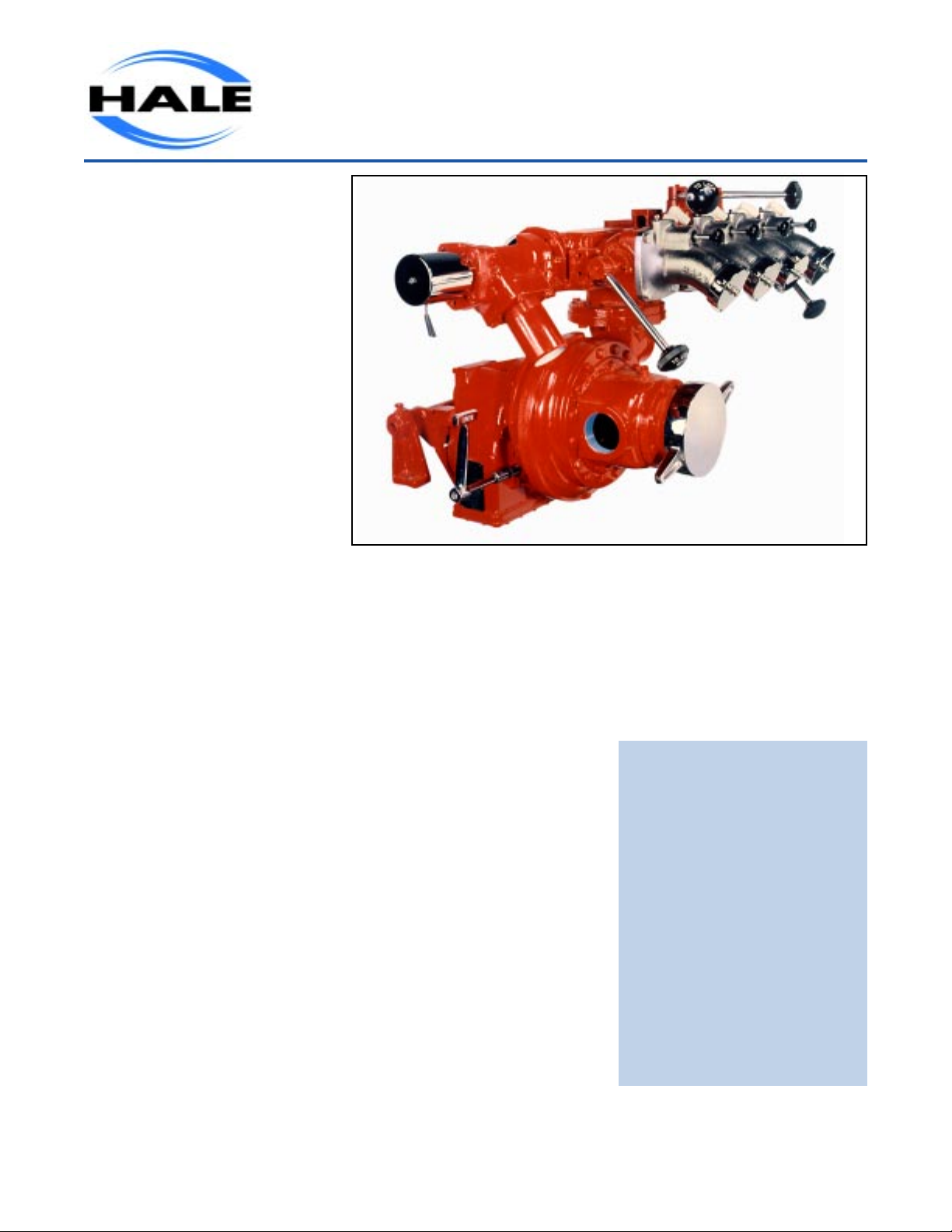
Hale Front Mounts provide
pump-and-roll capability with full
NFPA 1901 complialnce. They
have single-stage design for
ease of operation. Best of all,
theyre built by Hale.
For pump-and-roll grass fire
fighting or drafting from ponds
and streams, there are no
pumps like Hale Front Mounts.
They are extremely rugged, with
a range of capacities to meet
your needs. And they are built
with the same unique design
features that have made Hale
the leader in the fire-fighting
industry.
STANDARD FEATURES
Bronze impeller,
individually balanced and
matched with renewable
bronze clearance rings.
Electric rotary vane,
positive displacement
priming system with single
panel control activation.
Bronze fitted ball-type
droop discharge valves
with twist-to-lock handle
feature to gate valve in any
position.
Front Mount Fire Pumps
Corrosion-resistant stainless
steel pump shaft.
Oversized deep-groove ball
bearings for maximum
efficiency and long life.
Maintenance-free, self-
adjusting mechanical seal.
Oversized relief valve with
pressure control valve and
light.
Other standard features include
chrome-plated discharge and
suction caps, speed counter
connection and throttle indicator
lights.
HFM Series
Hale pumps go where the action
is. And when they get there,
they deliver. Thats why more
firefighters around the world rely
on Hale Front Mounts.
NFPA 1901 STANDARD RATINGS
HFM 75 750 GPM @ 150 PSI
2850 LPM @ 10.3 BAR
HFM 100 1000 GPM @ 150 PSI
3785 LPM @ 10.3 BAR
HFM 125 1250 GPM @ 150 PSI
4730 LPM @ 10.3 BAR
HFM 150 1750 GPM @ 150 PSI
5678 LPM @ 10.3 BAR
(GPM U.S. gallons per minute)
Page 6

Technical Specifications
Pump
Rated Capacities: 750,1000,
1250,1500 GPM ~ 150 PSI,
(2850, 3785, 4732, 5675 L/min
10.3 bar).
Type: Single-stage,
single-suction, gear-driven
centrifugal pump designed for
crankshaft-driven application,
with an integrated clutch for
engagement.
Impeller: Fine-grain bronze,
closed type, single-suction
mixed flow design, 10 inch (254
mm) diameter, accurately
machined and individually
balanced.
Clearance Rings: Bronze, front
and rear of impeller, easily
renewable.
Pump Shaft: Heat-treated
electric furnace
corrosion-resistant stainless
steel.
Packing: Maintenance-free,
self-adjusting mechanical seal.
Pump Casing: Fine-grain cast
iron with a minimum tensile
strength of 30,000 PSI. Tested
at 600 PSI hydrostatically by
Hale.
Suction Manifold: Fine-grain
cast iron with a minimum tensile
strength of 30,000 (206,842 kpa)
PSI. Tested at 600 PSI (41 bar),
hydrostatically and equipped
with fluid jacket for engine
coolant connection. Two 2-1/2
inch or 3 inch NPT pipe
connections are available.
Suction tube: Fine-grain cast
iron 4-1/2 inch NST (750 GPM),
5 inch NST (1000 GPM); 6 inch
NST (1250,1500 GPM).
Discharge Manifold: Fine-grain
cast iron with a minimum tensile
strength of 30,000 (206,842 kpa)
PSI tested at 600 PSI (41 bar)
hydrostatically. Designed with
six -3 inch cored openings to
accommodate discharge
requirements. Optional
manifolds available.
Discharge Valves: Hale Model
25BDT Valves (standard)
supplied as follows: three (750
GPM); four (1000,1250,1500
GPM). Hale Model 25BDT
Valves available as optional
equipment.
Gearbox
Drive Shaft: Heat-treated 1-1/4
in ten spline designed to accept
commercially available universal
joints.
Bearings: Heavy-duty ball
bearings, precision-ground to
size and lubricated from central
oil reservoir.
Gears: Both drive and pump
gears manufactured from the
highest quality steel alloy and
case hardened to provide
maximum strength and long life.
Ratios: Five ratios available to
provide maximum pump
performance and broaden
engine selection (gasoline and
diesel). Ratios: 1.40:1, 1.59:1,
1.81:1, 2.16:1, or 2.37:1.
Clutch: Integrated two-stage,
positive drive, wet-clutch design,
splash-lubricated from central
reservoir.
Mounting: Adjustable mounting
brackets provided for
standardization and to assist in
proper angularity requirements.
Pressure Control Device:
3 inch relief valve with control
standard (750,1000 and 1250
GPM); 3-1/2 inch relief valve with
control standard (1500 GPM).
Priming System: Hale Model
Electric Rotary Vane Priming
System, includes priming valve.
Meets or exceeds NFPA
1901standards.
Testing: Pump dynamometer
pretested by the Hale to ensure
compliance with NFPA 1901
standards.
Optional Accessories
Model TRV120 thermal Relief
Valve:
Automatically protects against
pump overheating.
TPM/P35 relief valve system.
Discharge and Suction Valves
Full-flow, quarter turn, ball-type with
locking handle.
Inline Valves: 1 inch through 3 inch,
full-flow, quarter turn, ball-type.
Drain Valves: Push-pull hose
bleeder valve and multi-port master
drain valve.
Strainers: Full-flow, basket-type
Shift: Air power shift system for
clutch.
Hale Products
A Unit of IDEX Corp.
700 Spring Mill Avenue
Conshohocken, PA 19428
USA
TEL: 610/825-6300
FAX: 610/825-9615
www.haleproducts.com
Note: Hale Products Inc. cannot assume responsibility for product failure resulting
from improper maintenance or operation. Hale is responsible only to the limits stated
in the product warranty. Product specifications contained in this material are subject
to change without notice. Bulletin 482 10/00 , rev 3 ©2000 Hale Products Inc.
Hale Products Europe
Charles Street
Warwick, CV34 5LR
England
TEL: (44) 01926 623000
FAX: (44) 01926 623666
www.haleeurope.com
Hale Products
Europe GmbH
Industriegebiet-Nord
Benzstrasse 4
64807 Dieburg Germany
TEL: (49) 06071 /92665
FAX: (49) 06071 /926677
MADE IN THE USA
Hale Products Asia
Singapore Rep. Office
63 Hillview Ave. #07-08
Lam Soom Industrial Bldg.
Singapore 669569
TEL: (65) 764-3575
FAX: (65) 764-4020
Page 7
Page 8
Page 9
Page 10
Page 11

Hale Model HFM
Front Mount Pump Operation Instructions
Pumping from Hydrant
1. Position chassis near hydrant and set parking brake. Shift truck transmission
to neutral position. Caution: Make sure that truck transmission shift quadrant
lock is used. Place wheel chocks in front and behind tires.
2. Attach one end of the suction hose to the hydrant and the other end to the
pump suction connection. Be sure the inlet strainer is installed and all drain
valves are closed.
3. Maintain engine idle speed, open hydrant, and slowly engage clutch in pump
transmission.
Caution: If clutch does not shift easily through its 180 degree travel,
do not force it, as this may cause serious damage to the pump
transmission. Instead, back the clutch off and re-engage it.
4. When discharge gauge registers pressure, open discharge line.
Note: It is not necessary to use primer when pumping from hydrant.
5. Accelerate engine and adjust discharge valves to obtain desired pressure and
volume.
6. When using soft suction hose between pump and hydrant, do not use
nozzles of larger capacity than the hydrant will supply.
Pumping from Booster Tank
1. Position chassis and set parking brake. Shift truck transmission to neutral
position. Caution: Make sure that truck transmission shift quadrant lock is
used. Place wheel chocks in front and behind tires.
2. Close all drain valves.
3. Maintain engine idle speed, open tank to pump supply line valve, and slowly
engage clutch in pump transmission.
Page 12

Caution: If clutch does not shift easily through its 180 degree travel, do
not force it, as this may cause serious damage to the pump
transmission. Back the clutch off and reengage it.
4. Pull out primer valve handle. When discharge gauge registers pressure, open
discharge line and release primer handle.
5. Accelerate engine and adjust discharge valves to obtain desired pressure and
volume. Caution: Do not try to pump a large volume of water, as suction line from
the tank will not handle it.
Pumping From Draft
1. Position chassis as dose to water source as possible and set parking brake.
Shift truck transmission to neutral position.
Caution: Make sure that truck transmission shift quadrant lock is used.
Place wheel chocks in front and behind tires. The pump will exceed the
rated capacity on a ten foot vertical lift, however, as the lift increases,
performance and capacity will decrease.
2 Attach hard suction hose to the suction nipple on pump and attach the hose
strainer to the other end. Be sure suction hose gasket and inlet strainer are in
place and all drain valves are dosed.
3. For best results, submerge suction strainer two feet or more in the water and
avoid pumping large volumes from shallow water.
4. Maintain engine idle speed, pull out primer handle, and slowly engage clutch in
pump transmission.
Caution: If clutch does not shift easily through its 180 degree travel, do not
force it, as this may cause serious damage to the pump transmission.
Instead, back the clutch off and re engage it.
5. When discharge gauge registers pressure, open discharge line, and release
primer handle. Caution: Care must be exercised not to operate pump without
water as this can seriously damage pump.
6. Accelerate engine and adjust discharge valves to obtain desired pressure and volume.
7. When suction hose must be carried over some obstruction such as a bridge rail, or if for
any reason the hose does not slope from pump to the water, the best results will be
obtained by priming with the discharge valve wide open
.
Page 13

One Last Word
The Hale Model HFM fire pump is an extremely rugged, dependable and
versatile unit. Its transmission housing, gears, shafts, bearings, pump casings,
and impeller are made of only the finest materials. Years of engineering
experience in hydraulic design and pump manufacturing stand behind each unit,
and are, in fact, the very reasons for its efficiency as a hydraulic machine.
Careful individual attention is given to each component as it is machined to exact
tolerances. Each pump is assembled by hand as a single unit. After assembly
and inspection, it is thoroughly tested under all phases of actual pumping
conditions.
In order that you may realize the full value and advantages of this
pump, it is suggested that a few practices be carefully followed. All men who
will be responsible for the actual operation of the pump should be thoroughly
familiar with it and its operation, both in theory and practice. This should
include regular drills in pumping from draft, hydrant and booster tank. Careful
instruction and practical experience will enable the men and their equipment
to work together as an effective fire-fighting team.
Regular and proper care of the pump itself and its related equipment
(suction and discharge hoses, gaskets, valves, etc.) is most important. A
periodical schedule for maintenance should be set up and strictly observed.
Page 14

Trouble Shooting Guide
Pump Fails to Prime or Loses Prime
1. Restriction at the Suction Strainer
a. Remove all leaves, dirt and other foreign material from the strainer.
b. Use extra caution when drafting from shallow water sources with mud, sand or gravel
bottom.
c Keep the strainer off bottom by placing it inside a barrel with the top cut down,
or use a similar method.
2. Suction Lift too High
a. Suction lift should not be attempted over 20 feet, except at low altitudes with the
equipment in new condition.
3. Suction Strainer too Near the Surface.
a. When pumping large volumes of water, the strainer should be submerged at least two feet
below the surface.
4. High Point in Suction Line.
a. Suction hose should slope from pump to source.
b. If a high point cannot be avoided, re-prime several times to avoid air pockets.
5. Primer Not Operated Long Enough.
a. A normal prime should be accomplished within 20 seconds at a 10-foot lift.
6. Defective Priming Line.
a. Check hose from pump to priming valve and also hose from priming
priming pump. Check for leaks or accumulations of foreign material.
b. If necessary, refer to the electric priming pump operation instructions supplied elsewhere in
this manual.
.
valve to the electric
Pump Will Not Deliver Capacity
1. Insufficient Horsepower
a. Check engine according to manufacturer's instructions, supplied with truck. b. See local
truck service garage.
2. Engine RPM too Low at Full Throttle.
a. Engine operated at hig h altitudes, engine horsepower decreases about 3 percent per 1000
feet above sea level. Consult manufacturer's instructions. Also due to insufficient
horsepower.
Page 15

3. Pump Wear Rings excessively Worn.
a. Excessive wear will allow severe internal leakage from the pressure side of the pump back to
the suction side, reducing the net pump capacity and pressure.
Engine RPM Higher than Necessary for Desired Volume in Pressure
1. Restriction in Suction Hose Strainer or Impeller Valves.
a. Inspect strainer to dear away all debris.
b. Pressure backwash will usually dear impeller vane when pump is topped.
c. Check condition of the suction hose. On an old, or defective hose, the liner may be pulled
loose when pumping, thus reducing the inside diameter of the hose itself.
2. Undersize Suction Hose.
a. When pumping at higher than normal lifts, or altitudes, use a larger suction.
3. Truck Transmission in Too Low a Gear.
a. Proper pumping gear is usually high, or direct drive. Consult apparatus instructions.
Pump Will Not Develop Sufficient Pressure
1. Often the remedies for low pump capacity will also correct low pressure.
2. Pump RPM too Low
a. Use a tachometer to check engine speed. Governor adjustment maybe required.
3. Pump Capacity Limits Pump Pressure.
a. Do not attempt to pump a greater volume of water at a given pressure than the pump was
designed to handle. Cavitation will result. Pump efficiency will be seriously impaired.
(NOTE: Prolonged pumping while pump is cavitating will damage impeller.)
b. Reduce volume by restricting discharge until the desired pressure is obtained.
Volume and Pressure
100% Capacity at 150 PSI 70% Capacity at 200 PSI 50% Capacity at 250 PSI
Page 16

Many Centrifugal Pump Troubles are Due to Air Leaks
Procedure to follow to detect possible air leaks
A. Start engine with pump disengaged and with pump drained.
B. Tightly close pump drain valve as well as booster tank suction and discharge
valves (if connected to a booster tank). Tighten caps on suction and discharge
openings. Then pull out primer handle.
C. With engine running at idling speed, observe hand on vacuum gauge until it
reaches a stationary position. This should be 20 inches or over, depending on
vacuum producing capacity of engine.
D. Release primer handle and carefully watch vacuum gauge hand. If hand drops
back rapidly, it indicates a leak, which must be located and corrected. If it stands
stationary, or moves back very slowly, it indicates either "no leak", or a minor leak,
which will not interfere with satisfactory operation.
E. Should test indicate a leak in pump proper, the stuffing box may need adjustment.
F Now remove discharge cap. If vacuum gauge hand returns toward zero, more
rapidly than before cap was removed, it indicates that the self-closing poppet valve
within the discharge manifold is not properly seated and this condition should be
corrected. G. When difficulty is experienced in locating an air leak, it may be found
by connecting pump suction to a hydrant. With hydrant pressure on pump, look for
water leaks, any one of which indicates a possible air leak. When connected to a
booster tank, there may be an air leak in booster line valves - in valve proper, or
around valve stem. The former may necessitate replacement of complete valve
while the latter may be corrected by replacing valve stem.
H. Do not overlook possibility of air leaks in suction hose or couplings. To test for
such leaks, connect suction hose to pump suction, place pump suction cap over
the end of the suction hose, and test in the same manner as described above as to
the motion of the vacuum gauge hand.
I. It is a very good idea to make periodic tests for air leaks.
NOTE: Excessive air leakage may delay, or even prevent priming
.
:
Page 17

Hale Model HFM
Recommended Preventive Maintenance Procedure
1. Lubrication.
The Hale pumps utilize oil-bath type lubrication of all gears and bearings in
the pump transmission. Oil level in the transmission should be maintained even with the
oil level plug, which is located on the lower left hand side of the gear case.
WARNING: Insufficient oil will result in serious damage to the all bearings and other
internal parts. An excessive amount of oil will cause the transmission to run at an
unusually high temperature, which may cause an oil breakdown.
WARNING: It is normal practice to ship pump to builder without oil, oil must be
added before operating.
It is recommended that the oil be changed every three months and after any prolonged
period of pumping. A good grade of SAE 30 non-detergent motor oil should be used in the
transmission. DO NOT use heavier oil. Check oil level at regular intervals.
Should your department be fortunate enough to have only a few calls during the year, it
will be beneficial to operate the pump once a week - perhaps during drill work.
2. Drafting. When pumping large volumes of water, the strainer should be submerged at least
two feet below the surface. Use extra caution when drafting from shallow water sources
with mud, sand or gravel bottom. Keep the strainer off bottom by placing it inside a barrel
with the top cut down, or use a similar method.
3. Salt Water Use. After pumping salt water, pump from a hydrant for a few minutes to flush
out the pump. Also, follow this procedure after pumping excessively dirty water.
4. Cold Weather. It is recommended that during cold weather the pump should be drained at
all times, except when kept in a heated fire house.
CAUTION: If long runs in very cold weather are expected (such as in rural areas), it
is wise to maintain a dry pump regardless of storage conditions.
Page 18

5. Final Test Before Housing Engine after a Fire or Drill. In addition to regular lubrication and
maintenance to the pump, the following pr ocedure is recommended to assur e proper
operation under emergency conditions:
a) Open discharge valves and remove caps.
b) Close drain valve(s).
c) Tighten suction caps.
d) Pull a prime until the compound gauge reaches about 20 inches of vacuum.
e) Watch gauge - if vacuum drops more than 10 inches in 10 minutes, an air lea k is prese nt.
All air leaks must be corrected before th e pump m ay be considered fully ser viceable.
Page 19

Pump Service Record
Pump Model ___________________ Pump Serial Number___________________
Check oil in gear case every 3 months; use SAE 20 non-detergent oil.
Change oil in gear case every 24 running hours.
Gear Case Oil Primer OIl Reservoir Comments or other Date/
Changed (Need Oil) Maintenance Performed Initials
YES NO YES NO
Page 20

Page 21

Page 22

Page 23

Page 24

Page 25

Page 26

Page 27

Page 28

Page 29

Page 30

Page 31

Page 32

Page 33

Page 34

Page 35

Page 36

Page 37

HOSE FRICTON LOSS (PSI PER 100 FEET)
G.P.M Flowing
3/4 Booster
1 Booster
1-1/2 Hose
G.P.M Flowing
1-1/2 Couplings
1-3/4Hose with
1-1/2 Couplings
2 Hose with
2-1/2 Hose
3 Hose with
2-1/2 Couplings
10 13.5 3.5 95 14 8
20 44 6 125 24 13
30 99 14 150 35 18
40 176 24 4 175 47 25 6
50 38 7 200 62 32 8
60 54 9 225 10
70 12 250 13 5 4
80 15 275 15
95 22 300 18
125 38 325 22 8
150 54 350 25 8
500 20 17
750 45 38
1000
NOTE: Add 5 PSI for each story of building and each wye orNOTE: Add 5 PSI for each story of building and each wye or
NOTE: Add 5 PSI for each story of building and each wye or
NOTE: Add 5 PSI for each story of building and each wye orNOTE: Add 5 PSI for each story of building and each wye or
siamese.siamese.
siamese.
siamese.siamese.
FF
riction Loss Calculariction Loss Calcula
F
riction Loss Calcula
FF
riction Loss Calculariction Loss Calcula
tions Courtions Cour
tions Cour
tions Courtions Cour
tesy IFSTtesy IFST
tesy IFST
tesy IFSTtesy IFST
A.A.
A.
A.A.
80
3 Hose
68
HALE PRODUCTS INC.
A UNIT OF IDEX CORPORATION
Page 38

HOSE FRICTON LOSS (PSI PER 100 FEET)
s
GPM FlowingGPM Flowing
GPM FlowingGPM Flowing
GPM Flowing
3/4" Booster3/4" Booster
3/4" Booster3/4" Booster
1" Booster
3/4" Booster
GPM FlowingGPM Flowing
GPM FlowingGPM Flowing
1-1/2" Hose1-1/2" Hose
1-1/2" Hose1-1/2" Hose
GPM Flowing
1-1/2" Hose
1-3/4" Hose with1-3/4" Hose with
1-3/4" Hose with1-3/4" Hose with
1-1/2" Couplings1-1/2" Couplings
1-1/2" Couplings1-1/2" Couplings
2" Hose with2" Hose with
2" Hose with2" Hose with
1-1/2" Couplings1-1/2" Couplings
1-3/4" Hose with
1-1/2" Couplings1-1/2" Couplings
1-1/2" Couplings
2" Hose with
1-1/2" Couplings
2-1/2" Hose
3" Hose with
3" Hose
2-1/2" Coupling
10 13.5 3.5 95 14 8 500
20 44 6 125 24 13 750
30 99 14 150 35 18 1000
40 176 24 4 175 47 25 6 1250
50 38 7 200 62 32 8 1500
60 54 9 225 10 1750
70 12 2 50 13 5 4 2000
80 15 2 75 15
95 22 3 00 18
125 38 325 22 8
150 54 350 25 8
500 20 17
750 45 38
3-1/2" Hose
GPM Flowing
4" Hose
5" Hose
1000 80 68
NOTE: Add 5 PSI for each story of building and each wye or siamese.NOTE: Add 5 PSI for each story of building and each wye or siamese.
NOTE: Add 5 PSI for each story of building and each wye or siamese.
NOTE: Add 5 PSI for each story of building and each wye or siamese.NOTE: Add 5 PSI for each story of building and each wye or siamese.
FF
riction Loss Calculariction Loss Calcula
F
riction Loss Calcula
FF
riction Loss Calculariction Loss Calcula
tions Courtions Cour
tions Cour
tions Courtions Cour
tesy IFSTtesy IFST
tesy IFST
tesy IFSTtesy IFST
A.A.
A.
A.A.
HALE PRODUCTS INC.
A UNIT OF IDEX CORPORATION
Page 39

DATA FOR PRACTICAL USE
WATER HORSE POWER =
GALLONS PER MINUTE X TOTAL HEAD IN POUNDS PER SQUARE INCH
1712
ONE GALLON WATER WEIGHS 8.33 POUNDS
ONE GALLON = 231 CUBIC INCHES
ONE CUBIC FOOT = 7.48 GALLONS
ONE POUND PER SQUARE INCH OF HEAD = 2.31 FEET HEAD OF WATER
ONE INCH OF MERCURY = 1.132 FEET OF WATER
ONE POUND PER SQUARE INCH = 2.0178 INCHES OF MERCURY = 27.68
INCHES OF WATER
POUNDS PER SQUARE INCH = FEET HEAD X .433
FEET HEAD = POUNDS PRESSURE X 2.31
ONE GALLON PER MINUTE X 3.785 = ONE LITER PER MINUTE
ONE CUBIC METER = 1000 LITERS
ONE IMPERIAL GALLON = 1.2 GALLONS
ONE POUND PER SQUARE INCH X .0690 = ONE BAR = .001 KPA
ONE BAR = 14.50 PSI
HALE PRODUCTS INC.
A UNIT OF IDEX CORPORATION
700 Spring Mill Avenue
Conshohocken, PA 19428
(610) 825-6300
Page 40

HOSE FRICTON LOSS (PSI PER 100 FEET)HOSE FRICTON LOSS (PSI PER 100 FEET)
HOSE FRICTON LOSS (PSI PER 100 FEET)
HOSE FRICTON LOSS (PSI PER 100 FEET)HOSE FRICTON LOSS (PSI PER 100 FEET)
G.P.M Flowing
500
750
1000
1250
1500
1750
2000
3-1/2 Hose
9.5
20
34
53
74
4 Hose
3
6
10
16
23
31
5 Hose
5
8
13
18
25
32
NOTE: Add 5 PSI for each story of building and each wye or siamese.
Friction Loss Caclulations Courtesy IFSTA.
700 Spring Mill Avenue
Conshohocken, PA 19428
HALE PRODUCTS INC.
A UNIT OF IDEX CORP.
(610) 825-6300
Page 41

HALE PRODUCTS INC.
A UNIT OF IDEX CORPORATION
GPM AT VARIOUS NOZZLE SIZES
1/2" 5/8" 3/4" 7/8" 1" 1-1/8" 1-1/4" 1-3/8"
PRESS.
NOZZLE
30 41 64 92 125 163 206 254 308
35 44 69 99 135 176 222 275 332
40 47 73 106 144 188 238 294 355
45 50 78 112 153 199 252 311 377
50 53 82 118 161 210 266 328 397
55 55 86 124 169 220 279 344 417
60 58 90 130 176 230 291 360 435
62 58 91 132 179 234 296 366 442
64 59 93 134 182 238 301 371 449
66 60 94 136 185 241 305 377 456
68 61 96 138 188 245 310 383 463
70 62 97 140 190 248 315 388 470
72 63 99 142 193 252 319 394 477
74 64 100 144 196 255 323 399 483
76 65 101 146 198 259 328 405 490
78 66 103 148 201 262 332 410 496
80 66 104 150 203 266 336 415 502
85 68 107 154 210 274 347 428 518
90 70 110 159 216 282 357 440 533
95 72 113 163 222 289 366 452 547
100 74 116 167 228 297 376 464 562
105 76 119 171 233 304 385 476 575
110 78 122 175 239 311 394 487 589
115 80 125 179 244 319 403 498 602
120 81 127 183 249 325 412 509 615
Page 42

HALE PRODUCTS INC.
A UNIT OF IDEX CORPORATION
700 Spring Mill Avenue
Conshohocken, PA 19428
(610) 825-6300
GPM AT VARIOUS NOZZLE SIZES
1-1/2" 1-5/8" 1-3/4" 1-7/8" 2" 2-1/4" 2-1/2" 3"
PRESS.
NOZZLE
30 366 430 498 572 651 824 1017 1464
35 395 464 538 618 703 890 1098 1581
40 423 496 575 660 751 951 1174 1691
45 448 525 610 700 797 1009 1245 1793
50 473 555 643 738 840 1063 1313 1890
55 496 582 675 774 881 1115 1377 1982
60 518 608 705 809 920 1165 1438 2071
62 526 618 716 822 935 1184 1462 2105
64 535 628 728 835 950 1203 1485 2138
66 543 637 739 848 965 1222 1508 2172
68 551 647 750 861 980 1240 1531 2204
70 559 656 761 874 994 1258 1553 2236
72 567 666 772 886 1008 1276 1575 2268
74 575 675 783 898 1022 1293 1597 2299
76 583 684 793 910 1036 1311 1618 2330
78 590 693 803 922 1049 1328 1639 2361
80 598 702 814 934 1063 1345 1660 2391
85 616 723 839 963 1095 1386 1711 2465
90 634 744 863 991 1127 1427 1761 2536
95 651 765 887 1018 1158 1466 1809 2605
100 668 784 910 1044 1188 1504 1856 2673
105 685 804 932 1070 1217 1541 1902 2739
110 701 823 954 1095 1246 1577 1947 2803
115 717 841 976 1120 1274 1613 1991 2867
120 732 859 997 1144 1301 1647 2034 2928
 Loading...