


FYR-PAK
OPERATING AND MAINTENANCE MANUAL
(Models: 2006 to Present)
MODEL NO. SERIAL NO.
Failure to follow the operating, lubrication, and
maintenance requirements set forth in the operating and instruction manual may
result in serious personal injury and/or damage to equipment.
A Hale pump is a quality product; ruggedly designed, accurately machined,
carefully assembled and thoroughly tested. In order to maintain the high quality
of your pump and to keep it in a ready condition, it is important to follow the
instructions on care and operation. Proper use and good preventive maintenance
will lengthen the life of your pump.
ALWAYS INCLUDE THE PUMP SERIAL NUMBER IN CORRESPONDENCE
Hale Products Inc.
A Unit of IDEX Corporation
700 Spring Mill Avenue
Phone: 610.825.6300
www.haleproducts.com
l
l
Fax: 610.825.6440
Conshohocken, PA 19428
l
800.220.4253
Class 1®
607 NW 27th Avenue l Ocala, FL 34475
Phone: 352.629.5020 l Fax: 352.629.2902
www.class1.com
l
800.533.3569
P/N 029-9100-01-0, Rev B, 8/2010

Fyr Pak
Operation and Maintenance Manual
2

Fyr Pak
Operation and Maintenance Manual
LIMITED WARRANTY
Hale Products Inc., herein referred to as “Hale,” warrants products of its manufacture to be free from
defects in material and workmanship, under normal use and service, for a period of two (2) years
or 400 hours of usage, whichever comes rst and the engine for up to one (1) year or 200 hours of
usage. The “Warranty Period” commences on the date the original buyer takes delivery of the product
from the manufacturer, or two and a half (2-1/2) years from date of shipment from Hale, whichever
period shall be the rst to expire. Products used for rental or contracting purposes are warranted for
a period of six months or 150 hours of usage, whichever comes rst. This limited warranty is effective
only if the equipment or apparatus is used as directed, is not subjected to misuse, negligence or
accident, and is not altered, treated or repaired by someone other than Hale or its designee. Items not
manufactured by Hale shall bear only the limited warranties offered by their respective manufacturers.
The exclusive remedy for breach of this warranty shall be to give Hale written notice thereof and to
request a Returned Goods Authorization. Upon receipt of the Returned Goods Authorization, the
buyer will return the nonconforming material to Hale F.O.B. its plant within thirty days after the buyer
has received the Returned Goods Authorization. Thereupon Hale at its own election shall repair
or replace the same or repay the price thereof. No proximate, incidental, consequential or other
damages shall be recoverable. Hale shall not be liable for consequential damages or contingent
liabilities including; but not limited to, loss of life, personal injury, loss of crops, loss due to re or
water property damage, and consequential trade or other commercial loss arising out of the failure of
Manufacturer’s product.
HALE MAKES NO WARRANTIES OF FREEDOM FROM PATENT INFRINGEMENT, OF
MERCHANTABILITY OF FITNESS FOR A PARTICULAR PURPOSE OR ARISING FROM A
COURSE OF DEALING OR USAGE OF TRADE OR OTHER LIKE OR DIFFERENT EXPRESS
OR IMPLIED WARRANTIES EXCEPT AS MADE ABOVE.
Hale Products Inc.
A Unit of IDEX Corp.
Conshohocken, PA. 19428
3
Fyr Pak
Operation and Maintenance Manual
NOTE: The Hale Fyr-pak is equipped with a United States Motor Power Inc., Power Bee Engine.
The engine is warranted by the manufacturer. Information on the engine should be referred to the
manufacturer or an authorized service center.
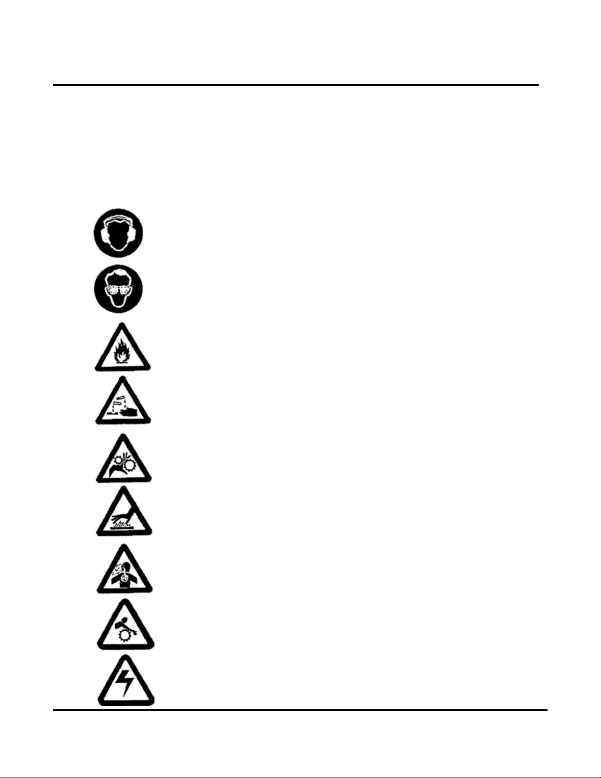
WARNING LABEL IDENTIFICATION
The equipment described in this manual contains one or more of the following warning labels.
The following chart identies the label and provides an explanation of the hazard associated
with the label.
HEARING PROTECTION REQUIRED WHEN OPERATING
EQUIPMENT
EYE PROTECTION REQUIRED WHEN OPERATING EQUIPMENT
EQUIPMENT CONTAINS FLAMMABLE FUEL
CORROSIVE HAZARD
ROTATING COMPONENTS
HOT SURFACES
DANGER OF CARBON MONOXIDE POISONING WHEN
EQUIPMENT IS OPERATING
OPERATING EQUIPMENT PRESENTS A DRAW-IN HAZARD
4

Fyr Pak
Operation and Maintenance Manual
ELECTRICAL SHOCK HAZARD
SAFETY PRECAUTIONS
Failure to follow the operating, maintenance and lubrication requirements set forth In this operating and
Instruction manual may result in serious personnel injury and/or damage to equipment. These “WARNING”
statements indicate potentially hazardous conditions for operator or equipment.
TAKE NECESSARY STEPS TO PROTECT PERSONNEL AND EQUIPMENT.
1 Carefully read “Engine Operating Instructions,” before attempting to operate, service, or
disassemble the engine or any of its parts.
2 Warning - Gasoline is a highly combustible fuel. The Improper use, handling, or storage of gasoline can
be dangerous. Prevent accidents by following these safety rules:
A. Use gasoline only as a fuel, never as a cleaning uid.
B. Use only an approved container to hold or store gasoline. Never store gasoline in familiar
containers such as milk containers or soda pop bottles.
C. Store gasoline in a cool location, out of the reach of children. Never store gasoline near heat or an
open ame.
D. Do not refuel with the engine running. Add fuel to a cool engine only. Spilled fuel on a hot engine
or mufer may cause a re or an explosion. Fill fuel tank out-of-doors and wipe up any spills.
E. Make sure all fuel lines and connectors are secure.
F. Provide a re extinguisher nearby when working with gasoline. Be sure extinguisher is
in operating condition; check the pressure gauge or indicator. Be familiar with its proper
use. Consult local re department for the correct type of extinguisher for your application.
Extinguishers rated ABC by the NATIONAL FIRE PROTECTION ASSOCIATION are
appropriate for most applications.
G. POSITIVELY NO SMOKING!!
3 DO NOT RUN THE ENGINE IN AN ENCLOSED AREA!! Exhaust fumes contain carbon monoxide that is
an odorless poisonous gas. If equipment is located in an enclosed area with an exhaust line to the outside,
regularly check the exhaust system for leaks. Be sure the area is well ventilated.
4 Do not operate equipment when mentally or physically fatigued.
5 Stay away from moving parts, avoid wearing loose tting clothes that could get caught in the equipment.
6 Keep the equipment and surrounding area clean. Cluttered areas invite accidents. Remove all oil deposits
from equipment and surrounding area. Accumulations of grease and oil may present a hazard.
7 All visitors should be kept at a safe distance from work area. Keep children away from equipment and
discharge hose. Do not allow children to hold discharge hose.
8 Be careful not to touch the exterior of a hot engine, especially the mufer and the surrounding area.
The engine is hot enough to be painful or cause injury.
9 Keep power shields and guards in place. Do not make adjustments and repairs while engine is running,
unless specied for in repairs. Use extreme caution around hot manifolds and moving parts.
10 Prevent accidental starting by always removing spark plug or by disconnecting and grounding spark plug
5

Fyr Pak
Operation and Maintenance Manual
wire before working on engine or the equipment driven by engine.
11 Maximum speed of the engine is set. Do not tamper with the controls to adjust to run at higher speeds.
Excessive speed increases the hazard of personal injury and reduces engine life
12 Familiarize yourself with all controls, learn how to stop engine quickly in a emergency.
13 When shutting off a gasoline engine, be sure It is completely stopped before leaving the work area.
14 For proper handling, storing and transporting fuel, follow fuel tank manufacturer’s instructions sheet and/or
instructions printed on tank.
15 If tank is equipped with a closing vented cap, open when pumping.
16 Check engine fuel level before initial start-up each day.
17 Flush pump with fresh, clear water if pump has been used to pump salt water or water containing sand.
18 During freezing weather, drain the pump, throttle actuator tubing, and discharge lines after each use.
19 The pump must be primed with the hand pump and the priming valve closed before starting engine.
20 Do not operate the unit while it is being carried.
21 Wear hearing protection when operating the unit.
6
Fyr Pak
Operation and Maintenance Manual
OPERATION AND INSTRUCTION MANUAL FOR ENGINE DRIVEN,
BACKPACK CENTRIFUGAL PUMPING UNIT
Introduction
PURPOSE
This operation and instruction manual is published to guide and assist in the installation, operation, lubrication,
maintenance, and repair of the Hale FYR PAK pumping unit. The installer and operator should understand this
manual before attempting to install or operate the unit.
IDENTIFICATION
Whenever a question arises regarding your pumping unit, contact your Hale Dealer for the latest available
information. This dealer will also be able to advise you of the nearest authorized engine dealer who can provide
service for the engine in your pumping unit. Finally, if additional help is needed, contact the Service Department
of Hale Products Inc.
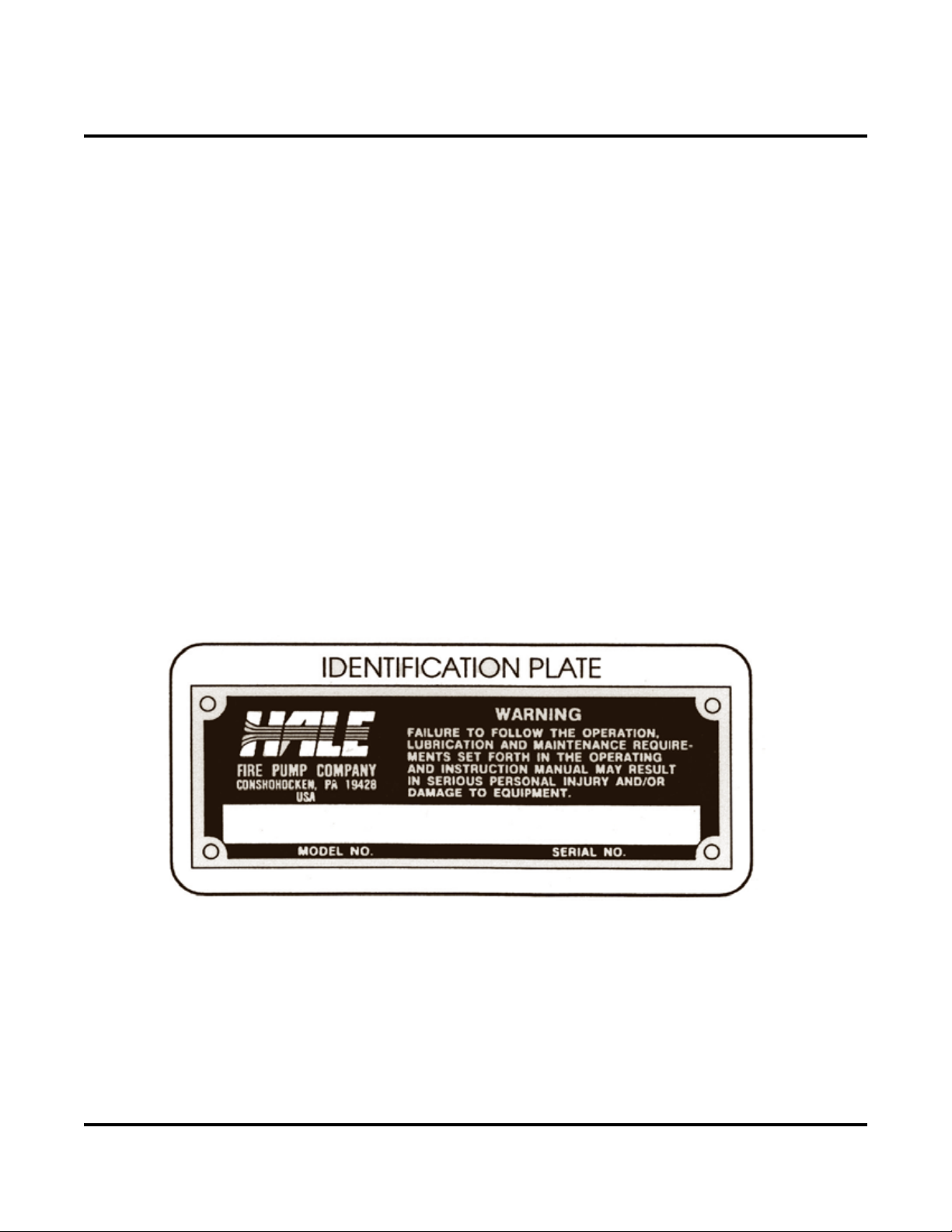
Please supply the complete pump model and serial numbers when requesting information or ordering parts.
The pump model and serial numbers are stamped (not cast) on the Hale nameplate. For your convenience, ll
in the information on the Hale nameplate below.
Also always mention both the model number and serial number of your engine when ordering engine parts.
These numbers are found on the engine identication plate attached to the engine.
To help identify the pump parts used in your FYR-PAK, a pump parts catalog is included toward the back of this
manual. To identify the engine parts used in your pumping unit refer to the engine manufacturer’s parts catalog.
DESCRIPTION GENERAL
The FYR-PAK is a lightweight portable centrifugal pump mounted on a modern adjustable backpack frame.
It consists of a Hale type 20FP single stage, centrifugal pump close coupled to an air-cooled, 2-cycle, single
cylinder, engine overspeed control switch, priming pump and priming valve. The unit will deliver discharge
pressures to 220 PSIG and ows to 75 GPM from draft
7

The FYR PAK pumping unit consists of 6 major subassemblies; the engine, pump, priming system, mounting
Fyr Pak
base, overspeed control switch and backpack frame.
Operation and Maintenance Manual
ENGINE
The lightweight engine is a single cylinder, two cycle, air-cooled version producing 8 hp (6 kW) from its
8.2 cu. inch (134 cc) displacement using a gasoline/oil fuel mixture. The engine is equipped with water resistant
solid state ignition, a pressure carburetor with built-in fuel pump, and an on/off ignition toggle switch.
The engine’s interior is protected from impurities by the use of a wire mesh element air ler, a 75 micron in-line
fuel ller, and an integral fuel strainer built into the fuel pump.
PUMP
The engine crankshaft extension serves as the pump shaft with an enclosed type bronze impeller mounted
directly on the shaft. The shaft is protected against corrosion by a bronze sleeve, an “O”-ring, and a mechanical
type, self-lubricating and adjusting seal. The impeller is hydraulically sealed by a replaceable, patented oating,
bronze clearance ring located in the suction of the aluminum volute body. The volute body is attached
to the cast aluminum pump head by four mounting scr
The pump head serves as the mounting bracket for the pump/engine assembly. It is attached to the mounting
base with rubber vibration shock mounts. It also incorporates a handle for positioning the unit of carrying short
distances.
ews.
PRIMING SYSTEM
The priming pump is a hand operated piston pump. Its purpose is to remove air from the pump allowing
atmospheric pressure to push water through the inlet hose into the pump. A priming valve is included which
controls air ow through the priming line.
MOUNTING BASE
The mounting base is an intermediate part to which the engine is attached with three shock vibration isolation
mounts. The base is attached to the backpack frame with four vinyl clad tubing clamps. The mounting base has
the overspeed control switch, priming pump mounting clamps and Hale nameplate attached to it.
OVERSPEED CONTROL
The overspeed switch control assembly is an added safeguard against overspeeding of the engine. The
overspeed switch is attached to the mounting base of the pumping unit below the carburetor. Attached to the front
of the overspeed switch is a exible transparent hose that is connected to the nozzle plate (riveted to the engine
fan housing). Connected to the back of the overspeed switch are two wires one goes to the engine’s ignition coil,
the other goes to ground (engine). The switch senses the air pressure generated by the engine’s cooling fan.
When the engine reaches a speed in excess of that which would normally occur the fan air pressure generated
will be sufcient to cause the switch to close thereby grounding the solid state ignition. The engine speed will
then decrease until the air pressure reaches a lower trip point, reactivating the ignition system and the engine will
accelerate. The engine will decelerate and accelerate alternately until the operating conditions are returned to
their normal mode.
BACKPACK FRAME
The backpack frame serves as a convenient means for transporting the FYR PAK unit over long distances. The
backpack frame is of conventional design incorporating adjustable shoulder straps and hip belt. The addition of
8

Fyr Pak
Operation and Maintenance Manual
a hip belt allows part of the weight to be carried on the hips.
PREPARATION
INSPECTION OF NEW UNIT
When unpacking unit do not discard cushioning materials, carton, or case until you are certain everything is
correct. Inspect carefully, perfect condition of the outside shipping container does not guarantee undamaged
contents. Check for loose, missing, or damaged parts. Also, check the packing slip for any additional parts.
After inspection proves satisfactory, discard all shipping material in a proper manner.
The idle speed, idle and main fuel mixture adjustment screws have been factory set. However, the idle and main
fuel mixture adjustment screws may require readjustment, especially for cold weather or high altitudes (see
“Engine Operating Instructions,” for adjustment procedure).
IDENTIFICATION OF CONTROLS
Air Cleaner: Low restriction cleanable expanded aluminum foil type element
Carburetor Fuel Strainer: Provides secondary fuel ltering for engine.
Carrying Handle: This is incorporated into the pump head
Choke: Reduces the amount of air entering the engine to correct the fuel-air ratio for cold start-up.
Discharge Hose Connection: Located on the air cleaner side of the unit for connection. Pump supplied with
1-1/2” female NPT, 1-1/2” Male NH or 1-1/2” Male ISO
Exhaust mufer: This is a spark arrested type that also reduces the amount of combustion noise emitted by
the engine.
Flexible Transparent Hose: Connected between the nozzle plate and the overspeed switch control. Allows
for visual inspection of dirt and water which may clog hose and reduce amount of pressure reaching switch.
Check regularly, be sure hose is not cracked, crimped, or kinked.
Fuel Line Connector: Connect the fuel line from the fuel caddie here.
Ignition Toggle Switch: When ipped to the “ON” position, opens circuit to ground allowing the magneto
to develop a spark for the ignition of combustion. Flipped to the “OFF” position, closed the circuit to ground
magneto.
In-Line Fuel Filter: Provides primary fuel ltering for engine.
Nozzle Plate: Riveted to the engine fan housing, directs air pressure to exible, transparent hose and
overspeed control.
Overspeed Control: For description refer to “Description -Overspeed Control”
Priming Valve: For description refer to “Description - Priming System”
Priming Pump: For description refer to “Description - Priming System”
Pump Inlet: Located at the end of the pump, tted with either 2” Female NPT, 2” Male ISO or 1-1/2” Male NH
thread.
9
Fyr Pak
Operation and Maintenance Manual
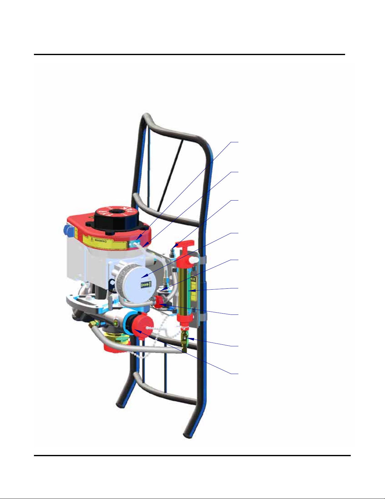
GENERAL COMPONENT IDENTIFICATION
NOZZLE PLATE
FLEXIBLE
TRANSPARENT HOSE
FUEL LINE
CONNECTOR
AIR CLEANER
OVERSPEED CONTROL
PRIMING PUMP
INLINE
FUEL FILTER
PRIMING VALVE
DISCHARGE
HOSE CONNECTION
10
Fyr Pak
Operation and Maintenance Manual
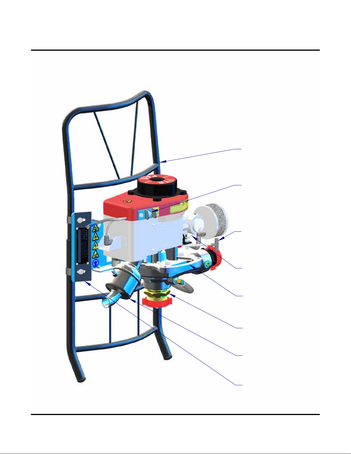
GENERAL COMPONENT IDENTIFICATION
BACKPACK FRAME
IGNITION
TOGGLE SWITCH
THROTTLE
CHOKE
CARRYING HANDLE
PUMP INLET
EXHAUST MUFFLER
BASE PLATE
11
Fyr Pak
Operation and Maintenance Manual
ENGINE CONTROLS
THROTTLE
CHOKE
INCREASE
CLOSE
12

Fyr Pak
Operation and Maintenance Manual
TRANSPORTING WARNING
Before transporting the FYR PAK, the fuel caddie MUST be disconnected from the engine and
the fuel drained as instructed under “STOPPING PROCEDURE” . Also, allow engine to cool.
The FYR PAK has a handle for moving and positioning the unit. Care should be taken not to drop or strike the
engine or pump as damage may result.
When transporting the unit by motor vehicle, care should be taken to fasten it down securely. Follow the
manufacturer’s instructions for transporting the fuel caddie.
When carrying the unit as a backpack, the hip belt and shoulder straps should be adjusted to satisfy the
individual.
There are two sets of holes in the frame for adjusting the hip belt.
The top end of the shoulder straps has three positions for attaching to the frame. Position the shoulder straps so
that they are horizontal from the shoulders to the fame. Adjustments are made by moving the adjustment pins on
one of the three holes found in the frame.
INSTALLATION
1. Choose a suitable location, as near to the source of water as possible, to place the FYR PAK and
attach intake and discharge hoses. When operating from draft, the inlet hose should slope continuously downward from the pump to the water.
2. Attach fuel line from remote tank.
CAUTION: Make sure connections on Intake and Discharge hoses match those supplied on the
pump or damage to threads will result. Damage may impede pump performance by allowing
leakage or preventing priming of the pump.
PRIME PUMP
It is recommended that the pump be primed before starting the engine.
a) Priming Procedure
1. The discharge must be closed either with a discharge valve, shutoff nozzle or by pinching the
discharge hose (use a pinch clamp if available.)
2. Open priming valve
3. Operate priming valve until water is discharged from priming pump
4. Close priming valve
5. Start engine. See starting procedures
6. Slowly open discharge valve until a steady stream is discharged
7. If an unsteady stream is discharged (incomplete prime) open priming valve and operate hand
primer to purge remaining air until a steady stream is discharged. Then, close priming valve
13

Fyr Pak
Operation and Maintenance Manual
and adjust throttle for desired output.
b) Alternate Priming Method: If the inlet hose is tted with a foot valve, the pump may be primed
by jabbing the end of the inlet hose in and out of the water until water expands the discharge
hose. The discharge line MUST be open when this method is used. Be sure the priming valve is
closed before starting engine.
OPERATION STARTING PROCEDURE
WARNING: DO NOT RUN THE ENGINE IN AN ENCLOSED AREA! Exhaust
fumes contain carbon monoxide which is an odorless and poisonous gas. Be
sure the area is well ventilated.
1. Make sure there is a FRESH mixture of gasoline and oil in the tank. Refer to “Fuel Specications,” for proper
amounts and type.
WARNING: Do not change or ll fuel while the engine running. Fill fuel tank out-of-
doors and away from any source of ignition. Wipe up any spills.
2. Connect fuel caddie to fuel line connector on engine base. Squeeze and release the priming bulb until
resistance is felt, indicating the fuel line is full. Further action will pump fuel past the check valve into the
carburetor, ooding it.
3. Close Choke
4. Open throttle slightly (1/4). Closed is down
5. Move ignition switch to “ON” position
6. Place foot on frame to prevent movement
7. Pull the starting handle slowly to bleed off some compression, then pull with a quick short stroke. Repeat as
necessary.
8. When engine starts, slowly open choke
9. Slowly open discharge valve
10. Set throttle to desired operating point.
NOTE: When operating from draft, especially on high lifts, do not increase engine speed
without a corresponding increase in pump pressure. If the engine speed increases with
no further increase in ow or pressure, reduce the throttle setting until the pressure or
ow decreases slightly and operate at that point.
14

Fyr Pak
Operation and Maintenance Manual
STOPPING PROCEDURE
1. Idle engine by pushing throttle lever down.
2. Move ON/OFF switch to OFF position.
3. Disconnect fuel caddie quick disconnect coupling, close cap and store fuel line.
4. Restart engine with water owing through pump and allow to idle until it stops from lack of fuel.
5. Allow lines to drain. Disconnect hoses.
CAUTION: Be careful not to touch the exterior of the engine, especially the mufer
and the surrounding area. The engine is hot enough to cause injury.
6. Without inlet and discharge caps in place, drain pump by tilting inlet end of pump downward. When pump is
drained, replace caps to prevent damage to threads.
RELAY PROCEDURE
For pumping water over long distances or up high vertical rises, it may be necessary to use several pumps in
series. When this is done, pressure (not exceeding 100 PSI) should be maintained at the inlet of the second and
subsequent pumps.
PREPARATION FOR STORAGE
WARNING: Prevent accidental starting by always removing spark plug or by disconnecting and
grounding spark plug wire before working on engine or pump.
NOTE: Replace the spark plug or wire only after all preparation is completed on both pump and engine.
1. Fuel System: If the unit is to be stored for any length of time, drain the fuel system by running until it stops as
instructed in “STOPPING PROCEDURE.”
2. Engine: See ENGINE MANUAL for storage instructions
3. Pump:
a. Follow the procedure under “Maintenance - Daily or Every 8 Hours” item 2, “Pump Inlet.”
b. Drain water from pump thoroughly. After the ow has ceased, pump should be turned over a few
revolutions so all water will drain from impeller.
c. While turning the pump over (using the starting handle), spray into the pump inlet and discharge
connections using either a white lithium or silicone type lubricant.
This treatment coats the inside of the pump and tends to prevent the clearance ring
and impeller hub from sticking due to corrosion.
d. Spray the threads of the inlet and discharge connections with either a while lithium or
silicone type lubricant.
15

Fyr Pak
Operation and Maintenance Manual
LUBRICATION AND MAINTENANCE
FUEL AND LUBRICANT SPECIFICATIONS:
Gasoline: Use clean, fresh, “regular grade unleaded” or “low lead” type. When “regular” or “low-lead” is
unavailable, an “unleaded” type fuel may be used; however, it should be limited to emergency use only. Oil
must be mixed with the gasoline. Refer to fuel mixture below.
Oil: Use a good quality Outboard motor oil or equivalent. The oil should meet or exceed the following typical
specications: TC-W3TM, NMMA, [API] TC, JASO FC, or ISO-L-EGO. Gasoline must be mixed with the oil,
refer to the fuel mixture below.
FUEL MIXTURE:
The engine used in the FYR-PAK requires that oil be mixed with the gasoline. For ease of starting, it is
desirable to have a fresh mixture of fuel; therefore, mix only an amount of fuel you anticipate using in the near
future. As a guide, the engine consumes approximately one gallon (3.8 L) per hour at full throttle (depending on
load), less at partial throttle.
To mix fuel, add oil to a small amount of gasoline in a clean container, then add the rest of the gasoline and
shake well.
NOTE: Do not mix oil and gasoline in the FYR-PAK fuel tank, it will be difcult to get good mixing.
Also if the fuel container has been still for an extended period, shake container before lling fuel tank.
The correct ratio of oil to gasoline is one (1) part oil to 24 parts gasoline (1:24). Table 1 shows various quantities
of fuel mixture and the amount of oil and gasoline required.
Approximate Quantity of
Fuel Desired Oil Gasoline
One Gallon (plus)
(3.9 Liters)
Three Gallons (plus)
(11.8 Liters)
Five Gallons (plus)
(19.7 Liters)
5 oz.
(158 ml.)
16 oz.
(473 ml.)
27 oz.
(789 ml.)
1 Gallon
(3.8 L.)
3 Gallons
(11.4 L.)
5 Gallons
(18.9 L.)
TABLE 1
SAFETY PRECAUTIONS:
1. DO NOT RUN THE ENGINE IN AN ENCLOSED AREA Be sure the area is well ventilated.
2. Stay away from moving parts. Avoid wearing loose clothing that could pose a catch risk.
3. Keep the equipment and surrounding area clean. Cluttered areas invite accidents.
4. Keep power shields and guards in place. Do not make adjustments and repairs while the engine is running,
unless specied for in repairs.
16

Fyr Pak
Operation and Maintenance Manual
5. Do not run the pump more than two minutes without water in the pump
6. Be careful not to touch the exterior of a hot engine, especially the mufer and the surrounding area.
7. Prevent accidental starting by always removing spark plug or by disconnecting and grounding spark plug wire
before working on engine or pump.
8. When working on any part of the fuel system be sure the unit is cool. Remove any sources of heat or ame.
ABSOLUTELY NO SMOKING!
Reassembly Note:
Before reassembly begins, visually inspect parts. See that parts are clean; all sealing surfaces are free of
corrosion and nicks. Remove any metal chips from casting cavities and tapped holes. Also, inspect for
any damaged or excessively worn parts which should be replaced.
MAINTENANCE SCHEDULE
DAILY OR EVERY 8 HOURS:
1. Leaks - (gaskets, fuel, seals, washers, and water): Check for any leaks before operating unit. These leaks
must be repaired before operating.
2. Pump Inlet: Remove any debris that might collect in the inlet, impeller eye, or the inlet hose strainer.
MONTHLY OR EVERY 25 HOURS:
1. Clean Air Filter aluminum foil element as follows:
NOTE: Service air cleaner more often under dusty conditions.
a) Remove (2) screws and washers so foil element and end plates can be removed
b) Wash foil element in kerosene or liquid detergent and water
c) Dry foil element by shaking out excess water. Use compressed air if available.
d) Install foil element, end plates, screws and washers on carburetor.
2. Spark Plug: Clean and regap at .030 inch (.8 mm). Spark plug type is champion #RL 86C,
NGK #BR5HS, AC #R46FF Motorcraft #AER6, and FramAutolite #426.
CAUTION: Do not blast clean spark plug. Blasting material could lodge in recesses of plug and
eventually work loose, permanently damaging aluminum bore. Spark plug should be cleaned
by scraping or wire brushing and washing with a commercial solvent.
3. Fuel Filters
General
a. Place the unit in a horizontal position.
b. Disconnect fuel caddie
c. Place a rag under the carburetor and fuel line to catch any fuel spillage.
d. Refer to lter maintenance below.
e. Wipe up any additional fuel spillage and discard rag in an approved safety container.
17

Fyr Pak
Operation and Maintenance Manual
In-Line Fuel Filter:
a. Remove the two clamps from both sides of lter and pull hoses using a slight twisting motion.
b. Observe hoses for any signs of cracking or deterioration and replace if necessary.
c. Install a new lter with the word “IN” toward fuel tank. Replace clamps.
Carburetor Fuel Strainer:
a. Remove the screw holding the plastic cover in place (where the fuel line connects to carburetor).
Gently remove the cover, gasket and strainer screen.
b. Clean screen in a nonammable solvent and blow dry.
c. Replace strainer screen, gasket, cover and screw.
4. Hoses, Fittings and Tubes: Clean and check all hoses, ttings and tubes for signs of cracks, kinks,
deterioration, etc. They should have uniform bends; if any are kinked or collapsed they should be
replaced. Fittings and clamps should be tight, but not over tight
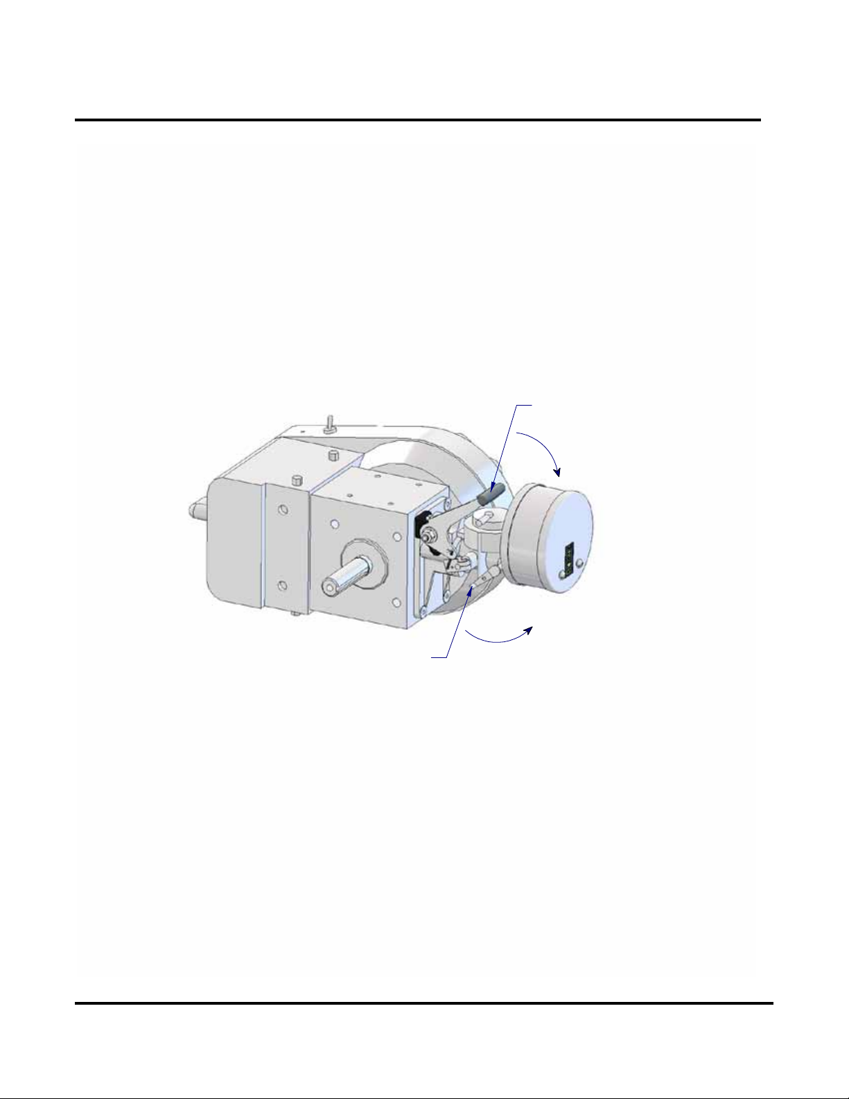
SEASONAL OR AS REQUIRED:
1. Engine Cooling System: Clean the starter screen, ywheel (fan), and engine cooling ns. Foreign
matter may clog cooling system after prolonged service. Continued operation with a clogged cooling
system causes severe overheating and possible engine damage.
a. Remove the four screws that fasten the fan housing to the support plate and remove the two
screws that fasten the fan housing to the sheet metal cylinder cover.
b. Remove the exible transparent hose from nozzle plate and the spark plug wire from spark plug.
c. Carefully lift the fan housing from engine, push the spark plug and overspeed switch wires rubber
grommet from housing. Reach inside of housing and disconnect the magneto wire from ignition
switch. The fan housing can now be completely removed and cleaned.
d. Remove the four screws that fasten the sheet metal cylinder cover to engine; be careful, the
lower two holes have small spacers between the cover and engine.
e. To reassemble engine; reverse above procedures.
2. Pump: Except for draining the casing during freezing weather, the pump requires only an occasional
cleaning.
3. Removal of Pump/Engine Assembly:
WARNING: When working on any part of the fuel system, be sure the unit is cool. Remove any
sources of heat or ame.
ABSOLUTELY NO SMOKING!
3a. Removal of pump/Engine housing from Mounting Base
a) Place the unit in a horizontal position.
b) Remove the fuel line from the fuel line connector. Catch any fuel spillage with a rag. Dispose of the
rag in an approved safety container.
18

Fyr Pak
Operation and Maintenance Manual
c) Disconnect the overspeed switch wire at the connector. Disconnect the short overspeed switch
ground wire by pulling spade connector from the overspeed switch.
d) Remove the overspeed switch tubing from the overspeed switch.
e) Remove the three locknuts from the vibration isolators that fasten them to the pump mounting base.
f) Lift the pump/engine assembly from the mounting base.
4. Assembly of Pump/Engine to Mounting Base
Assembly is the reverse of the removal procedure above.
5. Repair or Replacement of Any Components in Pump (Replacing mechanical Seal):
a) Remove pump/engine assembly from mounting base. Refer to item 3 “Removal of Pump/Engine
assembly.”
b) Remove the four screws that fasten the volute body to the pump head. Remove the volute body
c) Remove the impeller retaining screw and washer.
ATTENTION: The impeller screw is left hand threaded.
NOTE: To prevent the engine from rotating, when removing the impeller screw, place a long 3/8” screw
or 3/8” diameter bar through one of the pump head mounting holes and a at bar in one of the impeller
cavities.
d. Remove impeller by putting hardwood wedges on each side of impeller, between impeller
and pump head. The wedges should bear against impeller disc directly behind impeller
vanes to prevent damaging the impeller; refer to gure 4. Tap end of engine shaft with
a Soft (rawhide, rubber) headed mallet, while maintaining pressure with wedges until
impeller comes off.
DO NOT PUT TOO MUCH PRESSURE ON WEDGES
e) With impeller removed, remove the impeller key.
f) Remove the spring and carbon section (sealing washer) of mechanical seal from engine crankshaft
sleeve. Observe the ceramic seal seat and carbon sealing washer. If they are scored or lip on the
sealing washer is worn or cracked, replace complete assembly.
g) If further disassembly is required beyond mechanical seal replacement, remove the four 5/16-18 x
2-1/2 Lg. screws and 5/16 at brass washers that fasten pump head to engine.
h) If mechanical seal ceramic seal was not removed previously, remove from head.
i) Pull engine crankshaft brass sleeve from shaft,
j) There is a replaceable clearance or wear ring used in this pump. Inspect impeller hub and clearance
ring bore, replace if any of these surfaces are scored or worn excessively.
19

Fyr Pak
Operation and Maintenance Manual
Pump Head
Bent or Cracked
Impeller disc
Impeller Disc
Impeller Cavity
Wedge
Impeller Vane
CORRECT INCORRECT
Wedge
Reassembly Note:
Before Reassembly visually inspect parts. See that parts are clean and all sealing surfaces are free of corrosion
and nicks. Remove any metal chips from casting cavities and tapped holes. Also inspect for any damaged or
excessively worn parts which should be replaced.
a. Coat the engine crankshaft with a thin layer of gasket sealer, such as, Loctite Gasket Eliminator 504
b. Lubricate the groove in the pump shaft sleeve using a multipurpose grease and install “O”-ring in
groove. Slide this assembly on engine crankshaft.
c. Position pump head on engine and align holes. If original screws are in good condition, reuse, but
apply a thread locking adhesive, such as Loctite Threadlocker 242 or equal to threads. If original
screws were damaged, or corroded, replace with four new screws. When installing screws use a new
brass sealing washer under the head of each screw.
Note: Hale has available small tubes of Loctite Threadlocker 242 adhesive (0.5 cc). Hale
P/N: 029-0010-01-0.
d. Coat rubber cup of mechanical seal seat with dish soap or Pac Ease and press into pump head
with polished surface toward you.
e. Coat rubber on inside of mechanical seat carbon sealing washer with dish soap or Pac Ease.
Using a turning motion, push onto shaft sleeve until carbon lip comes into contact with the seat
installed in step d.
20

Fyr Pak
Operation and Maintenance Manual
CAUTION: Keep the seal seat and carbon sealing washer surfaces clean. Be careful not to crack
or chip seal surfaces.
g. Line up keyway of impeller with keyway of shaft. Push impeller on shaft. Insert impeller key until
ush with face of impeller
f. Line up keyway of impeller with keyway of shaft; push impeller on shaft. Insert impeller key until
ush with face of impeller.
g. Coat end of shaft and impeller with a thin layer of gasket sealer.
h. Coat threads of a new impeller screw with a thread locking adhesive (Loctite 2440 or equal).
i. Mount impeller washer and impeller screw. Torque impeller screw to 10 ft/lbs
ATTENTION: The impeller screw is left hand thread.
If impeller clearance ring requires replacement proceed with the following steps. If impeller
clearance ring is in good condition, proceed to step “m”.
j. With the clearance ring removed from volute body, inspect clearance ring pins. If
these are damaged replace.
k. Apply a thin coat of oil or multipurpose grease to groove of impeller clearance ring
and install O-ring into groove. Coat the outside of clearance ring and O-ring with oil or
multipurpose grease.
l. Aligning the holes in impeller clearance ring with pins in volute body, press clearance
ring into volute body.
m. Coat the inside of clearance ring bore and outside of impeller hub with oil.
n. Install O-ring on pump head pilot and coat O-ring and pump head pilot diameter with
either oil or a multipurpose grease.
o. Mount volute body with clearance ring to pump head.
p. Install the pump/engine assembly to mounting base. Refer to item 4, “Assembly of
Pump/ Engine to Mounting Base”
21

Fyr Pak
Operation and Maintenance Manual
Appendix A
Parts Breakdown
22

Fyr Pak
Operation and Maintenance Manual
108-0620-06-0
REMOTE TANK, 6 GALLON
2
3
1
4
5
1
ITEM PART DESCRIPTION QTY UNIT
1 108-0620-05-0 TANK , FUEL, 6 GAL 1 EA
2 110192 SPACER, FUEL TANK, 6 GAL 1 EA
3 044-0260-00-0 VENT, AIR 1/8" MPT 1 EA
4 088-0250-00-0 COUPLING, MALE 1 EA
5 340-0061-02-0 HOSE, 1/4" FUEL 1 17"
6 010-0390-00-0 FILTER, 1/4" FUEL HOSE 1 EA
7 101-0640-00-0 DECAL, FUEL MIXTURE (NOT SHOWN) 1 EA
6
23

Fyr Pak
168-5160-00-0
Operation and Maintenance Manual
ENGINE CONTROL PARTS, FYR-PAK/PORT
4
2
3
1
9
7
11
10
8
5
6
ITEM PART DESCRIPTION QTY
1 019-0961-00-0 THROTTLE BRACKET 1
2 097-2260-00-0 WASHER, POLY 2
3 012-0770-00-0 THROTTLE LEVER 1
4 012-0160-03-0 HANDLE, T-KNOB 1
5 012-0850-00-0 LINKAGE, THROTTLE 1
6 101-0650-00-0 DECAL, CHOKE 1
7 097-6020-01-0 WASHER, SPRING 1
8 097-0020-02-0 WASHER, FLAT 1/4" 1
9 018-1210-02-0 SCREW, HEX HEAD 1/4-20 X 1" 1
10 110-1206-02-0 NUT, NYLOCK, 1/4-20 1
11 018-1205-02-0 SCREW, HEX HEAD 1/4-20 X 5/8" 1
1
1 SUPPLIED WITH ENGINE
ENGINE SHOWN FOR
ILLUSTRATIVE PURPOSES ONLY
24

Fyr Pak
Operation and Maintenance Manual
178-55XX-01-0
INTAKE/DISCHARGE ADAPTER KIT
METRIC (ISO)
1
2
3
4
9
8
FASTENING RIVET
INCLUDED WITH
ASSEMBLY 547-0191-40-0
9
178-5580-01-0 (INTAKE)
QTYITEM PART DESCRIPTION
1 007-0470-01-0 ADAPTER, 2" MPT X 2" ISO 1
2 008-0100-08-0 CAP, 2" ISO(BSP) 1
8 368-0010-01-0 CHAIN, PLATED 1
9 102521 SCREW, PAN PH 8-32 X 3/8" 1
1
178-5590-01-0 (DISCHARGE)
ITEM PART DESCRIPTION QTY
3 007-0480-01-0 ADAPTER, 1-1/2" MPT X 1-1/2" ISO 1
4 008-0100-07-0 CAP, 1-1/2" ISO(BSP) 1
8 368-0010-01-0 CHAIN, PLATED 1
9 102521 SCREW, PAN PH 8-32 X 3/8" 1
1
1 INCLUDED WITH CAP
PUMP AND BASE ASSEMBLY SHOWN
FOR ILLUSTRATIVE PURPOSES ONLY
25

Fyr Pak
178-55XX-00-0
Operation and Maintenance Manual
INTAKE/DISCHARGE ADAPTER KIT
STANDARD (NH)
5
7
6
7
9
8
9
FASTENING RIVET
INCLUDED WITH
ASSEMBLY 547-0191-40-0
178-5580-00-0 (INTAKE)
ITEM PART DESCRIPTION QTY
5 007-0470-00-0 ADAPTER, 2" MPT X 1-1/2" MALE NH 1
7 008-0100-06-0 CAP, 1-1/2" NH 1
8 368-0010-01-0 CHAIN, PLATED 1
9 102521 SCREW, PAN PH 8-32 X 3/8" 1
1
178-5590-00-0 (DISCHARGE)
ITEM PART DESCRIPTION QTY
6 007-0480-00-0 ADAPTER, 1-1/2" MPT X 1-1/2" MALE NH 1
7 008-0100-06-0 CAP, 1-1/2" NH 1
8 368-0010-01-0 CHAIN, PLATED 1
9 102521 SCREW, PAN PH 8-32 X 3/8" 1
1
1 INCLUDED WITH CAP
PUMP AND BASE ASSEMBLY SHOWN
FOR ILLUSTRATIVE PURPOSES ONLY
26

Fyr Pak
Operation and Maintenance Manual
200-0722-55-0
OVERSPEED PRESSURE SWITCH ASSEMBLY
FYR-PAK/PORT
2
4
6
VIEW FROM TOP
OF ENGINE
3
*
5
10
9
7
8
1
ITEM PART DESCRIPTION QTY UNIT
1 H013-0931-00-0-A GROUND WIRE, OVERSPEED SWITCH 1 EA
2 505-0070-00-0 PLATE, OVERSPEED SWITCH 1 EA
3 340-0380-01-0 HOSE, PVC CLEAR 3/8" OD X 3/16" ID 1 7"
4 064-7100-00-0 RIVET, 1/8" DIA 2 EA
5 097-0750-01-0 WASHER, FLAT #10 2 EA
6 102460 SCREW, SH 10-32 X 5/8" 2 EA
7 101662 WASHER, LOCK #10 2 EA
8 102537 NUT, HEX 10-32 2 EA
9 200-0722-01-0 SWITCH ASY, OVERSPEED 1 EA
10 018-1205-02-0 SCREW, HEX HEAD 1/4-20 X 5/8" 1 EA
1
1 SUPPLIED WITH ENGINE
* ITEMS SHOWN FOR
ILLUSTRATIVE PURPOSES ONLY
27

Fyr Pak
Operation and Maintenance Manual
340-0060-04-0
FUEL HOSE ASSEMBLY
2
3
4
FLOW
DIRECTION
1
3
5
2
TANK ASSEMBLY SHOWN FOR
ILLUSTRATIVE PURPOSES ONLY
ITEM PART DESCRIPTION QTY UNIT
1 003-0080-00-0 PRIMING BULB 1 EA
2 088-0310-01-0 COUPLER, HOSE TANK 2 EA
3 242-0620-01-0 CLAMP, 1/2" 2 EA
4 340-0061-02-0 HOSE, 1/4" FUEL 1 35.5"
5 340-0061-02-0 HOSE, 1/4" FUEL 1 17"
28

Fyr Pak
Operation and Maintenance Manual
340-5000-00-0
FUEL LINE ASSEMBLY, FYR-PAK
*
2
5
1
3
ITEM P ART DESCRIPTION QTY UNIT
1 010-0340-00-0 FILTER, FUEL 1 EA
2 340-0061-02-0 HOSE, 1/4" FUEL 1 5.5"
3 340-0061-02-0 HOSE, 1/4" FUEL 1 5.5"
4 088-0250-00-0 COUPLING, MALE 1 EA
5 242-0620-01-0 CLAMP, 1/2" 4 EA
44
* ITEMS SHOWN FOR
ILLUSTRATIVE PURPOSES ONLY
29

Fyr Pak
501-1990-04-0
Operation and Maintenance Manual
PUMP, 20FP-C8 (PRESSURE PUMP)
12
6
ENGINE SHOWN FOR
ILLUSTRATIVE PURPOSES ONLY
9
14
16
4
11
10
20
7
3
5
19
21
8
2
15
17
13
1
18
ITEM PART DESCRIPTION QTY
1 002-0510-00-0 HEAD, PUMP 1
2 048-0770-00-0 SHAFT SLEEVE 1
3 016-0261-01-0 IMPELLER 1
4 001-0220-XX-X VOLUTE BODY 1
5 296-5240-00-0 MECHANICAL SEAL 1
6 217-0201-04-0 PLUG, PIPE 1/4 MPT 3
7 097-0381-00-0 WASHER, IMPELLER 1
8 040-0180-00-0 O-RING 1
9 064-0309-12-0 PIN, CLEARANCE RING 2
10 321-0121-00-0 RING, CLEARANCE 1
11 040-2320-00-0 O-RING 1
12 064-1024-01-0 PIN, SUCTION 1
13 040-1590-00-0 O-RING 1
14 102669 PLUG, PIPE 1/8 MPT 1
15 097-0810-00-0 WASHER, FLAT BRASS 4
16 018-1424-07-0 SCREW, HEX HEAD 5/16-18 X 2.5" 4
17 097-0140-01-0 WASHER, LOCK SPLIT 3/8" 4
18 018-1607-12-0 SCREW, HEX HEAD 3/8-16 X 7/8" 4
19 017-0060-01-0 KEY, IMPELLER 1
20 018-9350-00-0 SCREW, HEX HEAD 5/16-18 X 1" 1
21 217-0001-11-0 PLUG, PIPE 1/16 MPT 1
30

Fyr Pak
Operation and Maintenance Manual
503-5010-10-0
HAND PRIMER KIT - FYR PAK/PORT
10
9
8
PUMP AND BASE ASSEMBLY SHOWN
FOR ILLUSTRATIVE PURPOSES ONLY
9
ITEM PART DESCRIPTION QTY UNIT
1 003-1050-00-0 PRIMING PUMP 1 EA
2 082-0225-01-0 NIPPLE, 1/4 MPT X 1.5" GALV 1 EA
3 242-0550-00-0 CLAMP 1 EA
4 038-1130-00-0 VALVE, BALL 1/4 FPT 1 EA
5 082-0214-02-0 REDUCER BSHG, 1/4" MPT x 1/8" FPT BRASS 2 EA
6 082-0119-02-0 ADAPTER, 1/8 MPT X 3/8" HOSE 2 EA
7 340-0490-00-0 HOSE, 3/8" ID 1 10"
78
5
6
4
31

Fyr Pak
Operation and Maintenance Manual
510-0320-00-0
AIR INTAKE ASSEMBLY
FYR-PAK/PORT/FLOTE
ENGINE SHOWN FOR
ILLUSTRATIVE PURPOSES ONLY
ITEM PART DESCRIPTION QTY
1 010-0320-02-0 AIR FILTER 1
2 097-0160-01-0 WASHER, LOCK SPLIT #10 2
3 2718863 SCREW, RD SL 10-32 X 2.25" 2
1
2
3
32

Fyr Pak
Operation and Maintenance Manual
524-0051-30-0
EXHAUST ASSEMBLY - FYR-PAK/FLOTE
1
2
3
ENGINE SHOWN FOR
ILLUSTRATIVE PURPOSES ONLY
ITEM PART DESCRIPTION QTY
1 024-0330-01-0 EXHAUST MUFFLER 1
2 110-1406-02-0 NUT, NYLOCK 5/16-18 2
3 USM-247279 GASKET, MUFFLER 1
1
1 SUPPLIED WITH ENGINE
33

Fyr Pak
Operation and Maintenance Manual
529-5810-00-0
BACK PACK ASSEMBLY - FYR-PAK
6
4
BASE SHOWN
FOR ILLUSTRATIVE
PURPOSES ONLY
2
1
4
5
ITEM PART DESCRIPTION QTY
1 047-0210-00-0 FRAME, BACK BACK 1
2 242-0160-00-0 CLAMP, 1" ID 2
3 242-0160-01-0 CLAMP, 3/4" ID 2
4 097-0020-02-0 WASHER, FLAT 1/4" 8
5 110-1206-02-0 NUT, NYLOCK, 1/4-20 4
6 018-1210-02-0 SCREW, HEX HEAD 1/4-20 X 1" 4
3
3
2
34

Fyr Pak
Operation and Maintenance Manual
545-0430-01-0
ENGINE ASSEMBLY, FYR-PAK/PORT
8
9
4
10
1
7
5
3
2
12
6
11
ITEM PART DESCRIPTION QTY UNIT
1 045-0430-01-0 ENGINE, FYR PAK 1 EA
2 044-1050-00-0 SWITCH GUARD 1 EA
3 044-5260-00-0 SHIELD, SPARK PLUG, FYR-PAK 1 EA
4 160214-0 TERM 16-14 GA 5/32" DIA, MALE PIN 1 EA
5 340-0480-00-0 LOOM, 5/32" ID 1 4"
6 101-0620-00-0 DECAL, ON/OFF 1 EA
7 101-0710-00-0 DECAL, WARNING 1 EA
8 101-0680-00-0 DECAL, FYR PAK 1 EA
9 101-1530-13-0 LABEL, WARNING HOT SURFACE 1 EA
10 018-8180-00-0 STUD, 5/16-18 2 EA
11 064-7100-00-0 RIVET, 1/8" DIA 4 EA
12 018-1210-02-0 SCREW, HEX HEAD 1/4-20 X 1" 1 EA
1
1 SUPPLIED WITH ENGINE
35

Fyr Pak
Operation and Maintenance Manual
547-0191-40-0
BASE MOUNT ASSEMBLY, FYR-PAK/PORT
*
1
20
21
6
5
18
7
5
3
4
2
*
21
6
* ITEMS SHOWN FOR
ILLUSTRATIVE PURPOSES ONLY
36

Fyr Pak
Operation and Maintenance Manual
547-0191-40-0
BASE MOUNT ASSEMBLY, FYR-PAK/PORT
11
9
24
13
14
15
16
22
26 27
10
17
22
FOR RIVET INSTALLATION SEE
23
ASSEMBLY 178-55XX-XX-X
19
ITEM PART DESCRIPTION QTY UNIT
1 048-0830-00-0 SHOCK MOUNT 2 EA
2 005-0960-00-0 PLATE, ISOLATING 1 EA
3 048-0830-01-0 SHOCK MOUNT 1 EA
4 2678782 SPACER 1 EA
5 097-0210-01-0 WASHER 3 EA
6 110-1606-02-0 NUT, LOCK STOVER 3/8-16 2 EA
7 097-1110-00-0 WASHER, TEFLON 1 EA
8 DNF18-250FIB-3K TERMINAL, BLADE 1 EA
9 013-1610-26-0 TERMINAL, 5/32" RECEPTACLE 1 EA
10 340-0480-00-0 LOOM, 5/32" ID 1 18"
11 101-0500-00-0 NAMEPLATE SERIAL NUMBER 1 EA
12 101-0640-00-0 DECAL, FUEL MIXTURE (NOT SHOWN) 1 EA
13 101-1530-14-0 LABEL, WARNING CARBON MONOXIDE 1 EA
14 101-1530-10-0 LABEL, WARNING GASOLINE 1 EA
15 101-1530-18-0 LABEL, WARNING SHOCK HAZARD 1 EA
16 101-1530-13-0 LABEL, WARNING HOT SURFACE 1 EA
17 101-1530-15-0 LABEL, WARNING HEARING PROTECTION 1 EA
18 018-1205-02-0 SCREW, HEX HEAD 1/4-20 X 5/8" 2 EA
19 101-0301-00-0 DECAL, NOISE WARNING 1 EA
20 097-0020-01-0 WASHER, FLAT 1/4" 4 EA
21 110-1406-02-0 NUT, NYLOCK 5/16-18 4 EA
22 064-7100-00-0 RIVET, 1/8" DIA 7 EA
23 047-0200-00-0 PUMP MOUNTING BASE 1 EA
24 242-0540-00-0 CLAMP, WIRE 3 EA
25 2120006 RIVET, 3/16" DIA 1 EA
26 242-0530-00-0 CLAMP, PRIMING PUMP 2 EA
27 064-7110-00-0 RIVET, 5/32" DIA 2 EA
12
8
25
37

Fyr Pak
RECOMMENDED SPARES
Operation and Maintenance Manual
HALE 20FP-C8 FYR-PAK PUMPING UNIT
PART NUMBER: 546-1550-50-0
FYR-PAK Engine Spares Kit
PART NUMBER QTY. DESCRIPTION
USM-K264063 1 Starter Kit
USM-K10009 2 Carburetor Gasket Kit
USM-K10013 2 Carburetor Repair Kit
USM-A175061-3 1 Carburetor
USM-010530 1 Strainer Screen
USM-010527 1 Strainer Cover
USM-560475-2 1 Ignition Coil
USM-G819-2 2 Industrial Cylinder Gasket Set
USM-A175013 1 Piston Assembly
USM-A175228 1 Needle Bearing
USM-250449 1 Ignition Switch
USM-C249227 3 Spark Plug
PART NUMBER: 546-1550-55-0
FYR-PAK Pump Spares Kit
PART NUMBER QTY. DESCRIPTION
040-0180-00-0 1 O-Ring, Shaft Sleeve
040-1590-00-0 1 O-Ring, Pump Housing
040-2320-00-0 1 O-Ring, Clearance Ring
064-0309-12-0 2 Clearance Ring Pins
064-1024-01-0 1 Suction Pin
097-0810-00-0 4 Brass Washer
296-5240-00-0 1 Mechanical Seal
029-0600-00-0 2 Alcohol Wipes
029-0610-00-0 1 PAC-EASE 2cc Tube
012-0160-03-0 1 T-Knob Handle
200-0722-01-0 1 Overspeed Switch Assembly
340-0380-01-0 7 inches Clear Hose
010-0340-00-0 3 Fuel Filter
010-0390-00-0 1 Hose Fuel Filter
003-0080-00-0 1 Priming Bulb
242-0620-01-0 4 Hose Clamp
010-0320-02-0 1 Air Filter
003-1050-00-0 1 Priming Pump
340-0490-00-0 10 inches Priming Pump Hose
38

 Loading...