

Page 1

tm
FoamLogix
Models 3.3 / 5.0 / 6.5 Electronic
Foam Proportioning System
Installation and Operations Manual
Hale Products Inc. ◆ A Unit of IDEX Corporation
700 Spring Mill Avenue
Telephone: 610-825-6300
Web: www.haleproducts.com
◆ Conshohocken, PA 19428 U.S.A.
◆ FAX: 610-825-6440
Manual p/n: 029-0021-68-0
Page 2

APPARATUS INFORMATION
ENGINE ______________________________________________
TRANSMISSION _______________________________________
MAXIMUM CAFS ENGINE RPM ___________________________
CAFS ENGINE SPEED RANGE ___________________________
NOTICE !
Class1 cannot assume responsibility for product failure resulting from improper
maintenance or operation. Class1 is responsible only to the limits stated in the
product warranty. Product specifications contained in this manual are subject to
change without notice.
All Class1 products are quality components -- ruggedly designed, accurately
machined, precision inspected, carefully assembled and thoroughly tested. In
order to maintain the high quality of your unit, and to keep it in a ready condition, it
is important to follow the instructions on care and operation. Proper use and good
preventive maintenance will lengthen the life of your unit.
ALWAYS INCLUDE THE UNIT SERIAL NUMBER
IN YOUR CORRESPONDENCE.
ECO NO REV CHANGE FROM BY DATE APVD
0602 A Initial Release, for Printing LwH 08/10/2007 MAL
Manual p/n: 029-0021-68-0, Rev. -A
Printed in U.S.A.
HALE PRODUCTS, INC.
A Unit of IDEX Corporation
Conshohocken, PA 19428 USA
DRAWN BY LwH ISSUE DATE
© Hale Products, Inc. 2007
NOT TO BE REPRODUC ED OR USED TO
MAKE OTHER DRAWI NGS OR MACHINE RY.CHECKED BY PRW 08/10/2007
All Rights Reserved
COPYRIG HT ©
Page 3

Table of Contents ❑
Contents Page
FoamLogix 3.3 / 5.0 / 6.5 Installation and Operations
How to use this manual ........................................................................................ 11
1 Safety Precautions................................................................................................. 13
1.1 Definitions......................................................................................................................... 13
1.2 Guidelines ......................................................................................................................... 14
1 System Overview................................................................................................... 19
2.1 Rotary Gear Pump............................................................................................................ 19
2.2 Control Unit....................................................................................................................... 19
2.3 Water FLow Sensor.......................................................................................................... 20
2.4 Feed Back Sensor ........................................................................................................... 20
Table 2-1: Maximum Foam Solution Flows..........................................................................20
2.5 Tank Selector Valves ....................................................................................................... 21
Air Dual Tank Selector (ADT) ...........................................................................................................21
Manual Dual Tank Selector (MDT II) ................................................................................................ 21
Manual Single Tank (MST)...............................................................................................................22
2.6 Low Pressure Strainer ..................................................................................................... 22
Hale FS Series Strainers ..................................................................................................................22
2.7 Ordering Information ....................................................................................................... 23
2.8 Hale Foam System Specifications .................................................................................. 24
Figure 2-2: Foam Pump Installation Envelope Dimensions.................................................25
Figure 2-3: Foam Pump Installation Envelope Dimensions, ADT Option Only....................26
2.9 System Configuration ...................................................................................................... 27
Hale Foam Proportioner System, Models 3.3, 5.0 or 6.5..................................................................27
Figure 2-4: FoamLogix Available Models ............................................................................ 27
Figure 2-5: Hale Foam Proportioner Systems, Models 3.3, 5.0 and 6.5.............................. 27
2.10 Cable Harness .................................................................................................................. 28
Figure 2-6: Power Connection Wire Harness ..................................................................... 28
2.11 Dual Foam Concentrate Tank System Options ............................................................ 29
Figure 2-7: Dual Tank Foam Concentrate Tank System Options........................................29
FoamLogix 3.3 / 5.0 / 6.5 Installer / Operations Manual
p/n: 029-0021-68-0
3
Page 4

❑ Table of Contents
Contents - continued Page
2.12 Dual Foam Concentrate Tank Options........................................................................... 30
2.13 Single Foam Concentrate Tank Options ....................................................................... 31
2.14 Strainer Options .............................................................................................................. 32
2.15 Low Tank Level Sensor Options ................................................................................... 33
2.16 Flow Sensors.................................................................................................................... 34
2.17 Check Valve Manifolds .................................................................................................... 35
2.18 Remote Activation Switch Option ................................................................................. 36
2.19 Check Valves, Flanges, Gaskets ................................................................................... 37
2.20 Elbows and Mini Manifolds ............................................................................................ 38
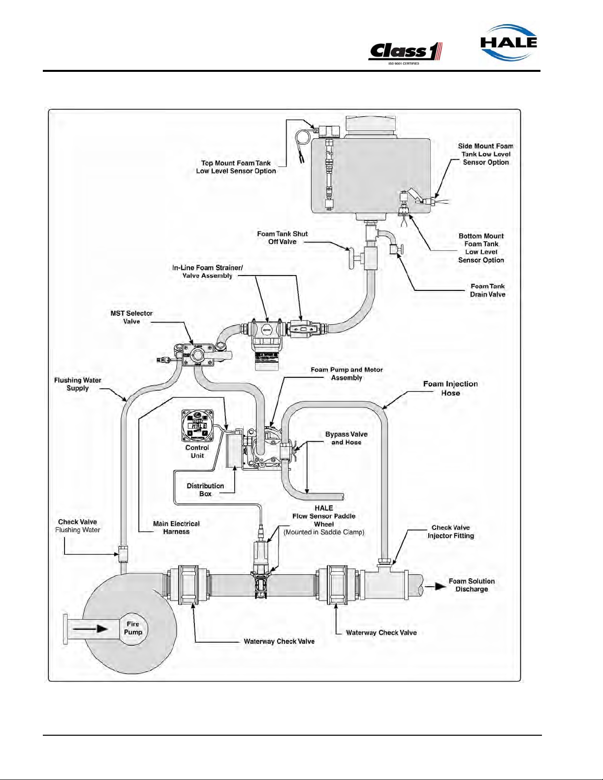
2.21 Hale Foam System Layout Drawings ............................................................................ 39
Figure 2-10: Typical Single Foam Concentrate Tank ..........................................................39
Figure 2-11: Single Foam Tank with MST and In-Line Strainer/Valve Assembly ................ 40
Figure 2-12: Single Foam Tank with MST and FS Series Strainers .................................... 41
Figure 2-13: Dual Foam Concentrate Tanks, with MDT II and In-Line
Strainer/Valve Assembly.................................................................................................42
Figure 2-14: Dual Foam Concentrate with MDT II and FS Series Strainer Assembly ......... 43
Figure 2-15: Dual Foam Concentrate Tanks, with ADT and In-Line
Strainer/Valve Assemblies..............................................................................................44
Figure 2-16: Dual Foam Concentrate Tanks with ADT and FS
Series Strainer Assemblies............................................................................................. 45
3 Installation ............................................................................................................. 47
3.1 Foam Pump and Motor Assembly .................................................................................. 48
3.2 Foam Concentrate Strainer............................................................................................. 48
3.3 Control Unit / Instruction Placard................................................................................... 49
3.4 Installer Supplied Components ...................................................................................... 50
Foam Concentrate Suction Hose ..................................................................................................... 50
Recommended Components .................................................................................................... 50
Recommended Components .................................................................................................... 51
Foam Concentrate Discharge Hose .................................................................................................51
Recommended Components .................................................................................................... 51
Foam Concentrate Bypass Hose...................................................................................................... 52
Recommended Components .................................................................................................... 52
Check Valves....................................................................................................................................52
4
FoamLogix 3.3 / 5.0 / 6.5 Installer / Operations Manual
p/n: 029-0021-68-0
Page 5

Table of Contents ❑
Contents - continued Page
3.4 Installer Supplied Components - continued
Flushing Water Hose ........................................................................................................................ 5 3
Foam Discharge Drains.................................................................................................................... 54
Electrical Requirements.................................................................................................................... 54
Figure 3-1: Recommended Relay Wiring Schematic ...........................................................55
Table 3-2: Primary Power Cable Sizes................................................................................ 55
FoamLogix Display ........................................................................................................................... 56
Foam Concentrate Tanks(s)............................................................................................................. 56
Table 3-3: Recommended Foam Tank Capacity .................................................................57
Foam Pump Mounting .....................................................................................................................57
Figure 3-4: FoamLogix Pump Installation ............................................................................ 57
Figure 3-5: Base Plate Mounting Hole Locations ................................................................ 58
Plumbing Installation......................................................................................................................... 59
Water and Foam Solution Plumbing .................................................................................................59
Figure 3-6: Typical Check Valve Manifold Installation ........................................................59
Optional Hale Piping Components....................................................................................................60
Figure 3-7: Typical Midship Pump Installation ....................................................................61
Figure 3-8: 4” (102mm) Check Valve Installation.................................................................61
“Waterway” Check Valves ................................................................................................................62
Flow Sensor ..............................................................................................................................62
Figure 3-9: Flow Sensor Tee Position Range ......................................................................62
Table 3-10: Pipe Size vs. Minimum Straight Run ................................................................63
Figure 3-11: Typical Reduced Size Sensor Piping Arrangement.........................................63
Figure 3-12: Flow Sensor Placement ..................................................................................64
Saddle Clamp Installation ..........................................................................................................64
Figure 3-13: Flow Sensor/Saddle Clamp Installation...........................................................65
Foam Pump Flush System ...............................................................................................................65
Dual Tank System .....................................................................................................................65
Single Tank System ..................................................................................................................65
No Tank Option .........................................................................................................................65
Foam Concentrate Plumbing............................................................................................................66
Foam Strainer Connection (In-Line Strainer/Valve).......................................................................... 66
Figure 3-14: In-Line Strainer/Valve Installation....................................................................67
To Install the In-Line Strainer/Valve Assembly ..........................................................................67
Figure 3-15: In-Line Strainer Mounting Bracket Layout ....................................................... 68
FS Series Strainer ............................................................................................................................69
To Install FS Series Strainers ....................................................................................................69
Figure 3-16: FS Strainer Orientation....................................................................................69
Figure 3-17: FS Strainer Mounting Dimensions...................................................................70
FoamLogix 3.3 / 5.0 / 6.5 Installer / Operations Manual
p/n: 029-0021-68-0
5
Page 6

❑ Table of Contents
Contents - continued Page
3.4 Installer Supplied Components - continued
Check Valve / Injector Fitting ....................................................................................................71
Figure 3-18: Check Valve/Injector Fitting Orientation.......................................................... 71
Figure 3-19: Check Valve / Injector Fitting Installation ........................................................71
Foam Concentrate Injection Hose.................................................................................................... 72
Figure 3-20: Injection and Bypass Hose Connections ......................................................... 72
Bypass Hose Connection .................................................................................................................72
Figure 3-21: Bypass Valve Assembly ..................................................................................73
ADT Option Air Connections ............................................................................................................ 73
Figure 3-22: ADT Option Panel Placard Layout Dimensions...............................................74
Figure 3-23: ADT Air Hose Connections, Part 1..................................................................74
Figure 3-24: ADT Option Air Hose Connections, Part 2 ...................................................... 75
3.5 System Plumbing Diagrams ........................................................................................... 77
Figure 3-25: Typical Single Foam Concentrate Tank ..........................................................78
Figure 3-26: Typical Single Foam Tank with MST and In-Line
Strainer/Valve Assembly................................................................................................. 79
Figure 3-27: Typical Single Foam Tank, with MST and FS Series Strainers....................... 80
Figure 3-28: Single Foam Tank with MST II and In-Line Strainer/Valve Assembly ............. 81
Figure 3-29: Typical Single Foam Tank with MST II and FS Series Strainers.....................82
Figure 3-30: Typical Single Foam Tank with ADT and In-Line
Strainer/Valve Assemblies.............................................................................................. 83
Figure 3-31: Typical Dual Foam Tanks, with ADT and FS Series Strainer Assemblies ...... 84
3.6 Electrical ........................................................................................................................... 85
Single and Dual Tank Electrical Harness Overview ........................................................................ 87
Figure 3-32: Single Tank Electrical Harness Overview .......................................................87
Figure 3-33: Dual Tank Electrical Harness Overview ..........................................................88
Control / Display Unit........................................................................................................................ 88
Figure 3-34: Control/Display Unit Mounting Dimensions ..................................................... 89
Figure 3-35: Distribution Box Connections .......................................................................... 90
Distribution Box Ground / Primary Power .........................................................................................90
RFI / EMI ..........................................................................................................................................91
Figure 3-36: Extra Cable Storage........................................................................................ 92
Flow Sensor Connections................................................................................................................. 92
“Low Level Sensor” Installation (Foam Tank)...................................................................................92
Figure 3-37: Low Level Sensor Mounting Options............................................................... 93
Figure 3-38: Side Mount Sensor Location Dimensions .......................................................93
Figure 3-39: Top Mount Sensor Dimensions ....................................................................... 95
Figure 3-40: Top Mount Low Level Sensor Assembly ......................................................... 97
6
FoamLogix 3.3 / 5.0 / 6.5 Installer / Operations Manual
p/n: 029-0021-68-0
Page 7

Table of Contents ❑
Contents - continued Page
3.6 Electrical - continued
Low Level Sensor Wiring.................................................................................................................. 97
Remote Activation Switch Option .....................................................................................................99
Figure 3-41: Remote Activation Switch Installation Dimensions........................................100
3.7 Start Up Check List ........................................................................................................ 101
Electrical .........................................................................................................................................101
Liquid ..............................................................................................................................................102
Foam Pump .................................................................................................................................... 103
Optional ADT ..................................................................................................................................103
3.8 Installation and Delivery Check List............................................................................. 104
3.9 System Installer Start-UP .............................................................................................. 105
Initial System Power Check............................................................................................................105
Figure 3-43: Initial Start-Up, System Ready Displays........................................................105
System Operation Check................................................................................................................106
Figure 3-44: Simulated Flow Mode Display ....................................................................... 107
4 User Setup and Calibration ............................................................................... 109
4.1 Initial End User Setup .................................................................................................... 109
Figure 4-1: Initial Start-Up, System Ready Displays..........................................................109
System Power Check ..................................................................................................................... 109
Priming the Foam Pump.................................................................................................................110
Figure 4-2: Simulated Flow Mode Display .........................................................................110
4.2 User Calibration.............................................................................................................. 111
Entering Passwords........................................................................................................................112
Figure 4-3: Password Sequence ....................................................................................... 112
Restoring Factory Defaults ............................................................................................................. 113
Figure 4-4: Password and Calibration Modes - Display..................................................... 113
Calibration....................................................................................................................................... 113
Flow Sensor Calibration.................................................................................................................. 114
Figure 4-5: Flow Sensor Calibration - Display ...................................................................114
Record Calibration Factors ............................................................................................................. 115
Figure 4-6: Flow Sensor Calibration Factor.......................................................................115
Simulated Flow ...............................................................................................................................115
Figure 4-7: Simulated Flow Calibration..............................................................................115
Foam Concentrate Injection Rate...................................................................................................116
Figure 4-8: Foam Concentrate Injection Rate Default Value, Tank “A” Shown ................. 116
FoamLogix 3.3 / 5.0 / 6.5 Installer / Operations Manual
p/n: 029-0021-68-0
7
Page 8

❑ Table of Contents
Contents - continued Page
4.2 User Calibration - continued
Foam Pump Feedback Calibration ................................................................................................. 116
Figure 4-9: Foam Pump Feedback Calibration, Tank “A” Shown ...................................... 117
Figure 4-10: Foam Concentrate Collection........................................................................117
Figure 4-11: Feedback Calibration Factor, Tank “A” Shown .............................................118
Exit and Save Calibration ............................................................................................................... 118
Figure 4-12: Exit and Save Calibration .............................................................................. 119
Relief Valve ....................................................................................................................................119
Figure 4-13: Relief Valve ...................................................................................................119
English to Metric Units....................................................................................................................120
5 Operation ............................................................................................................. 121
5.1 Description ..................................................................................................................... 121
Figure 5-1: Control Unit Identification ................................................................................ 121
5.2 Control Display Unit ...................................................................................................... 122
Control Unit Functions ....................................................................................................................122
Figure 5-2: Function Modes............................................................................................... 123
5.3 Reset Functions ............................................................................................................. 124
5.4 Foam Concentrate Injection Rate................................................................................. 124
5.5 Flush ............................................................................................................................... 125
Figure 5-3: Flush................................................................................................................ 125
5.6 Warning Messages ........................................................................................................ 125
Low Foam Tank Level Message.....................................................................................................126
Figure 5-4: Low Foam Tank Message, Tank “A” Shown ................................................... 126
Priming Message............................................................................................................................126
High Ambient Temperature Message............................................................................................. 127
Figure 5-5: Priming, HIGH Temperature and LOW Battery Messages.............................. 127
5.7 Priming the Foam Pump................................................................................................ 128
5.8 Normal Operation Summary ........................................................................................ 129
Energize System....................................................................................................... 129
Select Foam Tank..................................................................................................... 129
Figure 5-6: Normal Operation Summary Chart..................................................................129
Begin Foam Injection. ............................................................................................... 130
Change Injection Rate. ............................................................................................. 130
Read Injection Rate. ................................................................................................. 130
8
FoamLogix 3.3 / 5.0 / 6.5 Installer / Operations Manual
p/n: 029-0021-68-0
Page 9

Table of Contents ❑
Contents - continued Page
5.8 Normal Operation Summary - continued
Read Total Water or Foam Solution. ...................................................................... 130
Read Total Foam Concentrate .................................................................................. 131
Reset Totalized Values ............................................................................................. 131
End Foam Injection ................................................................................................... 131
5.9 Simulated Flow Mode Operation................................................................................... 131
Simulated Flow Sequence ............................................................................................................. 132
Figure 5-7: Simulated Flow Display Sequence ..................................................................132
5.10 Dual Tank System Selection ......................................................................................... 133
Figure 5-8: Dual Tank Selector Operating Positions .........................................................134
5.11 Flushing Hale FoamLogix.............................................................................................. 135
Figure 5-9: Hale MST Selector Operation .........................................................................136
5.12 Remote On/Off Switch Option....................................................................................... 137
To operate: .....................................................................................................................................137
Figure 5-10: Remote Activation Switch..............................................................................137
6 Maintenance ........................................................................................................ 139
6.1 Maintenance Procedures............................................................................................... 139
After each use.................................................................................................................................139
Monthly ...........................................................................................................................................139
Every Two (2) Months..................................................................................................................... 139
Annually .......................................................................................................................................... 139
7 Troubleshooting .................................................................................................. 141
7.1 User Diagnostics ............................................................................................................ 141
Figure 7-1: Distribution Box Overview ...............................................................................141
7.2 System Overview............................................................................................................ 142
Figure 7-2: FoamLogix, Closed Loop Flow Diagram ......................................................... 142
Distribution Box...............................................................................................................................143
Pump / Motor ..................................................................................................................................143
Bar Graph .......................................................................................................................................143
Summary ........................................................................................................................................ 144
7.3 Problem Isolation ........................................................................................................... 144
7.4 Flow Charts..................................................................................................................... 146
Chart 7-3: Hale FoamLogix System Troubleshooting Flow Chart...................................... 146
Chart 7-4: Power System Troubleshooting........................................................................ 147
FoamLogix 3.3 / 5.0 / 6.5 Installer / Operations Manual
p/n: 029-0021-68-0
9
Page 10

❑ Table of Contents
Contents - continued Page
Appendix A: Foam Concentrate Compatibility ............................................... 149
Chart A-1: Hale Class “A” Foam Concentrate Compatibility.............................................. 149
Chart A-2: Hale Class “B” Foam Concentrate Compatibility.............................................. 150
Reference ....................................................................................................................................... 151
Express Warranty................................................................................................153
8 Illustrated Parts Breakdown..............................................................................157
General............................................................................................................................ 157
Abbreviations ................................................................................................................. 157
8.1 Air Dual Tank Valve (ADT) Option ................................................................................ 158
8.2 Harness Components.................................................................................................... 160
8.3 Dual Foam Concentrate Tank Options......................................................................... 161
8.4 Single Foam Concentrate Tank Options ..................................................................... 162
8.5 Low Tank Level Sensor Options ................................................................................. 163
8.6 Flow Sensors.................................................................................................................. 164
8.7 Main Cable Harness, Single and Dual Tank ................................................................ 165
8.8 Check Valve Manifolds .................................................................................................. 166
8.9 Remote Activation Switch Option ............................................................................... 167
8.10 Check Valves, Flanges, Gaskets ................................................................................. 168
8.11 Elbows and Mini Manifolds .......................................................................................... 169
9 Plate Drawings..................................................................................................... 170
10
FoamLogix 3.3 / 5.0 / 6.5 Installer / Operations Manual
p/n: 029-0021-68-0
Page 11

How to use this manual
This manual is divided into eight (8) sections for clarity and ease of use. Each of
the following sections can be stand alone or used in conjunction with each other.
1SAFETY
This section must be carefully read, understood and adhered to strictly by
all installer/builders, operators and service personnel using the Hale FoamLogix, Models 3.3, 5.0 and 6.5, Electronic Foam Proportioning System. Do
not use or install the system until you have thoroughly read this section.
Failure to comply could cause serious injury to yourself and others, or damage to the system.
How To Use This Manual ❑
2 INTRODUCTION
System overview provides an introduction to the Hale FoamLogix Proportioning System along with guidelines for designing and ordering a complete
system.
3 INSTALLATION
This section offers installer/builder installation procedures, plumbing overview diagrams, electrical installation and startup and delivery check lists, to
assist the OEM with installation and initial setup of Hale FoamLogix Proportioning System on an apparatus.
4 USER CALIBRATION
User calibration is used by the installer and the end user for start-up and
calibration of the Hale FoamLogix Proportioning System to produce the
proper foam flow.
FoamLogix 3.3 / 5.0 / 6.5 Installer / Operations Manual
p/n: 029-0021-68-0
11
Page 12

❑ How To Use This Manual
5 OPERATION
The Operation section primarily used by the apparatus user for proper operation and maintenance of the Hale FoamLogix Proportioning System. It is a
guide to the operation of the system and includes operating procedures for
the most commonly used options.
6 GENERAL MAINTENANCE
This section describes the routine inspection and maintenance requirements for the Hale FoamLogix System.
7 TROUBLESHOOTING
If a problem develops, see this section for troubleshooting procedures.
8 PARTS IDENTIFICATION
Section 8 includes a parts breakdown of the most commonly used parts of
the FoamLogix 3.3, 5.0 and 6.5 Systems. Also see Section 8, Parts Identification and Drawing Package, heading “Illustrated Parts Breakdown” on
page 157.
9 PLATE DRAWINGS
Section 9 includes a listing of required installation and parts identification
drawings for the FoamLogix 3.3, 5.0 and 6.5 Systems. Also see Section
Parts Identification and Drawing Package, heading “9 Plate Drawings” on
page 170.
12
FoamLogix 3.3 / 5.0 / 6.5 Installer / Operations Manual
p/n: 029-0021-68-0
Page 13

1 Safety Precautions
THE HALE “FOAMLOGIX™” MODELS 3.3, 5.0 and 6.5 ELECTRONIC FOAM
PROPORTIONING SYSTEMS ARE DESIGNED FOR OPTIMUM SAFETY OF ITS
OPERATORS AND TO PROVIDE RELIABLE AND SAFE FOAM CONCENTRATE
INJECTION. FOR ADDED PROTECTION AND BEFORE ATTEMPTING INSTAL LATION OR OPERATION PLEASE FOLLOW THE SAFETY GUIDELINES LISTED
IN THIS SECTION. ADHERE TO ALL WARNING, DANGER, CAUTION AND
IMPORTANT NOTES FOUND WITHIN THIS GUIDE.
THIS SECTION ON SAFETY MUST BE CAREFULLY READ, UNDERSTOOD
AND ADHERED TO STRICTLY BY ALL INSTALLERS AND SYSTEM OPERATORS BEFORE ATTEMPTING TO INSTALL OR OPERATE THE FOAMLOGIX
FOAM PROPORTIONING SYSTEM.
WHEN DEVELOPING DEPAR TMENTAL APPARATUS OPERATING PROCEDURES, INCORPORATE THE WARNINGS AND CAUTIONS AS WRITTEN.
Safety Precautions ❑
IMPORTANT !
FoamLogix is a trademark of Hale Products, Incorporated. All other brand and
product names are the trademarks of their respective holders.
1.1 DEFINITIONS
DANGER – Immediate hazard which WILL result in severe personal injury
or death if the warning is ignored.
WARNING – Hazards or unsafe practices which COULD result in severe
personal injury or death if the warning is ignored.
DAN GER !
WARNING !
CAUTION – Hazards or unsafe practices which COULD result in minor or
moderate personal injury if the warning is ignored.
FoamLogix 3.3 / 5.0 / 6.5 Installer / Operations Manual
p/n: 029-0021-68-0
CAUTION !
13
Page 14

❑ Safety Precautions
NOTICE – Practices which could result in damage to the apparatus or other
property.
1.2 GUIDELINES
READ ALL INSTRUCTIONS THOROUGHLY BE FORE
BEGINNING ANY INSTAL LATION OR OPERATION PROCESS.
❑ Installation should be performed by a trained and qualified installer, or
your authorized Hale Products Service Representative.
❑ Be sure the installer has sufficient knowledge, experience and the proper
tools before attempting any installation.
❑ Make sure proper personal protective equipment is used when operating
or servicing the apparatus.
NOTICE !
❑ A foam tank low level sensor must be utilized to protect the Hale foam
proportioner from dry running. Failure to use a low level sensor with the
Hale Foam System voids warranty.
❑ DO NOT permanently remove or alter any guard or insulating devices, or
attempt to operate the system when these guards are removed.
Make sure all access/service panels and covers are installed, closed and
latched tight, where applicable.
❑ DO NOT remove or alter any hydraulic or pneumatic connections, electri-
cal devices, etc. DO NOT tamper with or disconnect safety features or
modify protective guards (such as covers or doors). DO NOT add or
remove structural parts. Doing so voids the warranty.
Any of the above could affect system capacity and/or safe operation of
the system and is a serious safety violation which could cause personal
injury, could weaken the construction of the system or could affect safe
operation of the FoamLogix Proportioning System.
WARNING !
NO MODIFICATIONS OR ADDITIONS MAY BE MADE TO THE FOAMLOGIX
PROPORTIONING SYSTEM WITHOUT PRIOR WRITTEN PERMISSION FROM:
14
Hale Products, Incorporated
Fire Suppression Division
700 Spring Mill Avenue
FoamLogix 3.3 / 5.0 / 6.5 Installer / Operations Manual
p/n: 029-0021-68-0
Page 15

Safety Precautions ❑
Conshohocken, PA 19428
Telephone: .........610-825-6300
Fax: ....................610-825-6440
❑ To prevent electrical shock always disconnect the primary power source
before attempting to service any part of the Hale FoamLogix System.
❑ All electrical systems have the potential to cause sparks during service.
Take care to eliminate explosive or hazardous environments during service and/or repair.
❑ To prevent system damage or electrical shock the main power supply
wire is the last connection made to the Hale Foam Propor tioner Distribution Box.
❑ Release all pressure then drain all concentrate and water from the sys-
tem before servicing any of its component parts.
❑ Do not operate the system at pressures higher than the maximum rated
pressure.
❑ Use only pipe, hose, and fittings from the foam pump outlet to the injector
fitting, which are rated at or above the maximum pressure rating at which
the water pump system operates.
❑ Hale Foam proportioning systems are designed for use on negative
ground direct current electrical systems only.
❑ Do not mount radio transmitters or transmitter cables in direct or close
contact with the FoamLogix Control Unit.
❑ Before connecting the cord sets and wiring harnesses, inspect the seal
washer in the female connector.
If the seal washer is missing or damaged, water can enter the connector
causing corrosion. This could resulting in possible system failure.
❑ Always disconnect the power cable, ground straps, electrical wires and
control cables from the control unit or other Hale Foam system equipment before electric arc welding at any point on the apparatus
Failure to do so could result in a power surge through the unit that could
cause irreparable damage.
❑ DO NOT connect the main power lead to small leads that are supplying
some other device, such as a light bar or siren.
The Hale FoamLogix, Models 3.3, 5.0 and 6.5, require 60 AMP minimum current.
❑ When operating the Hale FoamLogix in Simulated Flow Mode, an outlet
for the foam concentrate must be provided to prevent excessive pressure
buildup in the discharge piping or hoses.
FoamLogix 3.3 / 5.0 / 6.5 Installer / Operations Manual
p/n: 029-0021-68-0
15
Page 16

❑ Safety Precautions
❑ Unless engaged in Class “B” foam operations, the air dual tank (ADT)
toggle switch, or the manual dual tank (MDT) II selector handle must be
in the TANK “A” or FLUSH position. If either is in the FLUSH position
when the foam system is started, the foam pump runs for approximately
twenty (20) seconds, then SHUTS DOWN.
❑ Make sure the foam tank and foam concentrate suction hoses are clean
before making final connections to the foam pump. If necessary flush the
tank and hoses prior to making connection.
❑ Check all hoses for weak or worn conditions after each use. Ensure that
all connections and fittings are tight and secure.
❑ Ensure that the electrical source of power for the unit is a negative (–)
ground DC system, of correct input voltage, with a reserve minimum current available to drive the system.
❑ The in-line strainer/valve assembly is a low pressure device and CAN-
NOT withstand flushing water pressure in excess of 45 PSI (3 BAR).
When installing the in-line strainer in systems equipped with the Hale
MDT II or MST, make sure the in-line strainer/valve assembly is installed
on the “inlet” side of the valve.
If the strainer is subjected to flushing water, install Hale FS Series
strainers.
❑ When determining the location of the Hale FoamLogix System compo-
nents keep in mind piping runs, cable routing and other interferences that
could hinder or interfere with proper system performance.
❑ Always position the check valve/injector fitting at a horizontal or higher
angle to allow water to drain away from the fitting. This avoids the possibility of sediment deposits or the formation of an ice plug.
❑ The cord sets provided with each Hale Foam system are 100% electri-
cally shielded assemblies.
NEVER attempt to shorten or lengthen the molded cables. If necessary,
order longer or shorter cord sets to suit your application needs.
❑ Each cord sets provided is indexed to ensure correct receptacle installa-
tion (they inser t one way only).
When making cord set connections DO NOT force mismatched connections as damage can result in improper system operation.
❑ Make sure all connections are sound, and that each connection is
correct.
❑ The cables shipped with each Hale Foam system are 100% tested at the
factory with the unit. Improper handling and forcing connections can
damage these cables which could result in other system damage.
16
FoamLogix 3.3 / 5.0 / 6.5 Installer / Operations Manual
p/n: 029-0021-68-0
Page 17

Safety Precautions ❑
❑ There are no user serviceable parts inside Hale Foam system electrical/
electronic components.
Opening the distribution box, control unit, foam multiplexing display unit, etc., voids the warranty.
❑ Use mounting hardware that is compatible with all foam concentrates to
be used in the system. Use washers, lock washers and cap screws
made of brass or 300 series stainless steel.
❑ When making wire splice connections, make sure they are properly insu-
lated and sealed using an adhesive filled heat shrink tubing.
❑ ALWAYS connect the primary positive power lead from the terminal block
to the master switch terminal or the positive (+) battery terminal.
Use a minimum 4 AWG type SGX (SAE J1127) chemical resistant battery cable and protect with wire loom.
❑ Prevent corrosion of power and ground connections by sealing these
connections with the silicone sealant provided.
❑ Prevent possible short circuit by using the rubber boot provided to insu-
late the primary power connection at the Hale FoamLogix Distribution
Box.
FoamLogix 3.3 / 5.0 / 6.5 Installer / Operations Manual
p/n: 029-0021-68-0
17
Page 18

❑ Safety Precautions
Notes
______________________________________________________________
______________________________________________________________
______________________________________________________________
______________________________________________________________
______________________________________________________________
______________________________________________________________
______________________________________________________________
______________________________________________________________
______________________________________________________________
______________________________________________________________
______________________________________________________________
______________________________________________________________
______________________________________________________________
______________________________________________________________
______________________________________________________________
______________________________________________________________
______________________________________________________________
______________________________________________________________
______________________________________________________________
______________________________________________________________
______________________________________________________________
______________________________________________________________
______________________________________________________________
______________________________________________________________
______________________________________________________________
______________________________________________________________
______________________________________________________________
______________________________________________________________
______________________________________________________________
______________________________________________________________
______________________________________________________________
______________________________________________________________
______________________________________________________________
18
FoamLogix 3.3 / 5.0 / 6.5 Installer / Operations Manual
p/n: 029-0021-68-0
Page 19

1 System Overview
The Hale FoamLogix Models 3.3, 5.0 and 6.5 Foam Proportioning Systems are
completely engineered, factory matched foam proportioning systems that provide
reliable, consistent foam concentrate injection for Class “A” and Class “B” foam
operations.
Hale FoamLogix Foam Systems accurately deliver from 0.1% to 10.0% foam concentrate through a check valve/injector fitting, directly into the water discharge
stream. It is then fed as foam solution into a standard fog nozzle, an air aspirated
nozzle, or CAFS equipment, through the apparatus discharge piping. A properly
configured and installed foam system with Hale recommended components virtually eliminates contamination of the booster tank, fire pump and relief valve with
foam concentrate.
Introduction ❑
2.1 ROTARY GEAR PUMP
The hear t of the Hale FoamLogix 3.3, 5.0 and 6.5 systems is an electric
motor driven rotary gear pump. The pump is constructed of bronze and
stainless steel and is compatible with almost all foam concentrates. The
pump is close coupled to the electric motor thereby eliminating maintenance
of an oil-filled gearbox. A relief valve mounted on the foam pump and constructed of stainless steel, protects the foam pump and foam concentrate
discharge hoses from over pressurization and damage.
2.2 CONTROL UNIT
The control unit, mounted on the operator panel, is the single control point
for the FoamLogix system. Pressing the ON button starts foam concentrate
injection. A super bright digital LED display shows the:
❑ Water flow rate
❑ Total water flow
❑ Foam concentrate injection percentage
❑ Total foam concentrate used, depending on the display mode selected
A bar graph indicates the approximate system capacity being used. Adjustment of the foam concentrate injection rate is accomplished by pressing the
appropriate button while the system is operating.
FoamLogix 3.3 / 5.0 / 6.5 Installer / Operations Manual
p/n: 029-0021-68-0
19
Page 20

❑ Introduction
The control unit display also warns the operator if errors or abnormal operations occur in the system, such as low foam level.
2.3 WATER FLOW SENSOR
The foam concentrate injection rate is controlled by a computer chip in the
control unit for accurate, repeatable, reliable foam concentrate injection. A
water flow sensor constantly monitors water flow through the discharge piping. The information from the flow sensor is provided to the control unit by a
shielded cable. When the FoamLogix system is activated at the control unit
a signal is sent through the control cable to the distribution box to begin
foam concentrate injection. The distribution box then provides power to the
electric motor. As the motor rotates the pump, foam concentrate flows
through the foam pump discharge to the one piece check valve/injector fitting into the water discharge stream.
Note: All Hale FoamLogix Foam systems require a flow sensor for operation.
2.4 FEED BACK SENSOR
Injection
Rate
(Percent
%)
0.1 3,300 12,492 5,000 18,927
0.2 Not 6,245 2,500 9,464
0.3 1,100 4,164 1,667 6,310
0.5 660 2,498 1,000 3,785 1,300 4,921
1.0 330 1,249 500 1,893 650 2,461
3.0 110 416 167 632 216 818
6.0 55 208 83 314 108 409
GPM LPM GPM LPM GPM LPM
Table 2-1: Maximum Foam Solution Flows
A feedback sensor in the foam pump discharge measures foam concentrate
flow. The water flow rate and foam concentrate flow rate are constantly
compared by the computer chip in the control unit.
Maximum Foam Solution Flows
Model 3.3 Model 5.0 Model 6.5
Not
Applicable
20
The motor speed is constantly adjusted to maintain the operator selected
foam concentrate injection rate. Since the system is flow based, injection
rate remains constant regardless of changes in system pressure or the
number of discharges that are open (within the limits of the system).
FoamLogix 3.3 / 5.0 / 6.5 Installer / Operations Manual
p/n: 029-0021-68-0
Page 21

There are three models of Hale Foam systems covered by this manual. The
Hale FoamLogix Model 3.3 (3.3GPM / 12.5LPM), Model 5.0 (5.0GPM /
19LPM) and Model 6.5 (6.5GPM / 24.6LPM).
The maximum rated foam concentrate flow in gallons per minute is denoted
by the model number. Table 2-1: “Maximum Foam Solution Flows” on page
20 shows the system capacities at various foam concentrate injection rates
for each Hale FoamLogix Model.
The Hale FoamLogix 3.3, 5.0 and 6.5 system configuration is shown in Figure 2-2: “Foam Pump Installation Envelope Dimensions“ on page 25. Also
see Figure 2-3: “Foam Pump Installation Envelope Dimensions, ADT Option
Only” on page 26.
2.5 TANK SELECTOR VALVES
Selection of the desired foam concentrate tank with the ADT panel mounted
toggle switch or MDT II selector automatically changes the foam concentrate injection rate to the preset default rate for the selected foam tank. No
further operator intervention is required.
Introduction ❑
The ADT, MDT II and MST include the check valves and connection points
to provide foam pump flushing capabilities.
Air Dual Tank Selector (ADT)
The Air Dual Tank (ADT) valve is an air operated foam tank selector valve
that enables selection of foam concentrate dependent on fire ground operational demands.
The ADT is an integral par t of the foam pump and provides an electrical
interlock for the low tank level sensors and concentrate injection rate. A
panel mounted selector toggle switch with indicator lights controls foam concentrate tank selection and shows which foam concentrate tank is in use.
Manual Dual Tank Selector (MDT II)
The Manual Dual Tank (MDT II) selector valve is available for the Hale Foam
systems with dual tanks. The MDT II is a panel mounted, manually operated selector that provides selection of foam concentrate dependent on fire
ground operational demands.
FoamLogix 3.3 / 5.0 / 6.5 Installer / Operations Manual
p/n: 029-0021-68-0
21
Page 22

❑ Introduction
The MDT II also provides an electrical interlock for the low tank level sensors and concentrate injection rate. The MDT II is not suitable for top mount
operator panel installations and some side operator panels due to gravity
feed requirements of foam concentrate to the foam pump.
Manual Single Tank (MST)
Single tank foam systems can be configured with a Manual Single Tank
(MST) selector, which provides a flush function connection to the foam system electronic controls.
2.6 LOW PRESSURE STRAINER
A low pressure foam concentrate strainer is mounted at the inlet of the foam
pump. The strainer protects the pump from debris that might accumulate in
the foam concentrate tank. The strainer and valve assembly has a composite nonmetallic housing with stainless steel mesh strainer element and
includes a service shut-off valve and mounting bracket.
The assembly uses a 1-1/4” (32mm) NPT thread and is supplied with fittings
for connection of either 1-1/4” (32mm) ID, 1” (25mm) ID or 3/4” (19mm) ID
foam concentrate suction hose. The in-line strainer and valve assembly is
suitable for use with both Class “A” and Class “B” foam concentrates and is
designed for installations where the strainer is mounted in the foam pump
suction line.
The strainer and valve are low pressure devices and are designed for installations where the strainer IS NOT subject to HIGH pressure flushing water.
Hale FS Series Strainers
Hale FS series strainers (FS15 and FS25) are panel mounted with a 500
PSIG (34 BAR) pressure rating, suitable for use where flushing water pressure must pass through the strainer.
The FS15 strainer uses 3/4” (19mm) NPT connection ports and a 1-1/2”
NST cap. It is suitable for use with Class “A” and low viscosity Class “B”
foam concentrates.
The FS25 strainer uses 1” (25mm) NPT connection ports and a 2-1/2” NST
cap. It is suitable for use with both Class “A” and Class “B” foam
concentrates.
22
FoamLogix 3.3 / 5.0 / 6.5 Installer / Operations Manual
p/n: 029-0021-68-0
Page 23

Introduction ❑
2.7 ORDERING INFORMATION
Use the current Hale FoamLogix Foam System Price List and Order Form to
help ensure a complete matched system is provided to the end user.
Use the following procedure when ordering a Hale FoamLogix Foam System. Follow all steps to ensure that a complete system is ordered:
1. Check Hale Foam system product information update (Bulletin #961) for
the latest information and advice for foam system selection. A copy of
Bulletin #961 is located at the back of this manual.
2. Determine the type of foam concentrate being used in the system and
ensure system compatibility by referring to the Hale Foam Concentrate
Compatibility Char t. Also see Heading “Appendix A: Foam Concentrate
Compatibility” on page 149.
3. Determine the Hale Foam system needed.
❑ Model 6.5 (24VDC motor only)
❑ Model 5.0
❑ Model 3.3
❑ 12 VDC
❑ 24 VDC motor
4. Determine tank selector needed based on the number of foam concentrate tanks installed.
❑ ADT........... for dual tank systems
❑ MDT II ....... for dual tank systems (not available for model 6.5)
❑ MST .......... for single tank systems
❑ No Select .. for single tank systems –
System installer/builder must provide flushing water connection to the
foa m pump.
5. Determine strainers needed.
❑ In-line Strainer and Valve Assembly
❑ FS 15 Strainer
❑ FS 25 Strainer
FoamLogix 3.3 / 5.0 / 6.5 Installer / Operations Manual
p/n: 029-0021-68-0
23
Page 24

❑ Introduction
6. Determine the low tank level sensors needed.
❑ Side Mount
❑ Bottom Mount
❑ Top Mount Assembly
7. Select the flow sensor, then the mounting weld fitting or saddle clamp
based on discharge pipe size.
8. Select harness length.
❑ 10 feet flow sensor x 15 feet controller
❑ 15 feet flow sensor x 20 feet controller
9. Additional Hale components available to enhance system operation and
ease installation include:
❑ Waterway Check Valves
❑ Manifolds
❑ Flanges
❑ Foam Tanks, etc.
10. Components shown in bold type represent the best value performance
system. All components listed have been engineered and tested with
Hale foam systems to provide optimum system performance. Using the
information provided and the detailed ordering procedures on the option
order form ensures a complete Hale foam system is ordered, thus eliminating delays caused by missing components.
11. System components are shown in the following heading “Hale Foam
System Specifications.”
2.8 HALE FOAM SYSTEM SPECIFICATIONS
(See Figure 2-2: “Foam Pump Installation Envelope Dimensions,” on page
25.) Also see Figure 2-3: “Foam Pump Installation Envelope Dimensions,
ADT Option Only” on page 26.
24
Foam Pump ....................................... Rotary Gear Positive Displacement
Rated Foam Concentrate Output
Model 3.3 ......................................................................3.3 GPM (13 LPM)
Model 5.0 ......................................................................5.0 GPM (19 LPM)
FoamLogix 3.3 / 5.0 / 6.5 Installer / Operations Manual
p/n: 029-0021-68-0
Page 25

Introduction ❑
Rated Foam Concentrate Output - continued
Model 6.5 ...................................................................... 6.5 GPM (25 LPM)
Maximum System Operating Pressure
Model 3.3 ....................................................................... 350 PSI (24 BAR)
Model 5.0 ....................................................................... 200 PSI (14 BAR)
Model 6.5 ....................................................................... 200 PSI (14 BAR)
Maximum Operating Temperature.................................... 160° F (71° C)
Pump Motor
Standard - Models 3.3 and 5.0 ........................... 3/4 HP (0.6 kW), 12 VDC
Standard - Model 6.5 .......................................1-1/4 HP (0.9 kW), 24 VDC
Optional .............................................................. 3/4 HP (0.6 kW), 24 VDC
Operating Ampere Draw...... 30 AMPS at 12 VDC (15 AMPS at 24 VDC)
Maximum Ampere Draw ...... 60 AMPS at 12 VDC (30 AMPS at 24 VDC)
FoamLogix 3.3 / 5.0 / 6.5 Installer / Operations Manual
p/n: 029-0021-68-0
Figure 2-2: Foam Pump Installation Envelope Dimensions
(Configured for use with MDT II, MST or No Tank Selection Options.)
25
Page 26

❑ Introduction
26
Figure 2-3: Foam Pump Installation Envelope Dimensions, ADT Option Only
FoamLogix 3.3 / 5.0 / 6.5 Installer / Operations Manual
p/n: 029-0021-68-0
Page 27

2.9 SYSTEM CONFIGURATION
Hale Foam Proportioner System, Models 3.3, 5.0 or 6.5
All Hale Foam systems include a: Foam Pump/Motor Assembly, Control
Unit, Main Harness and Check Valve/Injector Fitting. Also see Section 8
“Illustrated Parts Breakdown” on page 157.
Introduction ❑
Foam Pump/Motor Assembly
(Shown with Bypass Valve when configured
for MDT II, MST or No Tank Selector Option)
Check Valve/Injector Fitting
p/n: 038-1790-00-0
Control Unit
p/n: 111530
FoamLogix Model Part Number
Model 6.5, with 24VDC Motor 501-4480-04-0
Model 5.0, with 12VDC Motor 501-3130-04-0
Model 5.0 with 24VDC Motor 501-3130-03-0
Model 3.3 with 12VDC Motor 501-3120-03-0
Model 3.3 with 24VDC Motor 501-3120-04-0
Figure 2-4: FoamLogix Available Models
Figure 2-5: Hale Foam Proportioner Systems, Models 3.3, 5.0 and 6.5
FoamLogix 3.3 / 5.0 / 6.5 Installer / Operations Manual
p/n: 029-0021-68-0
27
Page 28

❑ Introduction
2.10 CABLE HARNESS
For cable harness overviews, see Section “ 9 Plate Drawings,” beginning on
page 170. Also see Figure 2-6: “Power Connection Wire Harness” on page
28.
p/n: 113436 ...Control Head Harness, 10’ x 4’ (3.1 x 1.2 m)
10’ - Flow Sensor x 4’ - Motor Control
p/n: 113438 ...Control Head Harness, 10’ x 14’ (3.1 x 4.3 m)
10’ - Flow Sensor x 14’ - Motor Control
p/n: 113439 ...Control Head Harness, 15’ x 19’ (4.6 x 5.8 m)
15’ - Flow Sensor x 19’ - Motor Control
p/n: 113437 ...Control Head Harness, 32” x 5.5’ (0.81 x 1.7 m)
32” - Flow Sensor x 5.5’ - Motor Control
p/n: 113434 ...Single Tank Moto Control
p/n: 113435 ...Dual Tank Motor Control
p/n: 113437 ...Control Head Harness, 32” x 5.5’ (0.81 x 1.7 m)
32” - Flow Sensor x 5.5’ - Motor Control
p/n: 113437 ...Control Head Harness, 32” x 5.5’ (0.81 x 1.7 m)
32” - Flow Sensor x 5.5’ - Motor Control
Figure 2-6: Power Connection Wire Harness
28
FoamLogix 3.3 / 5.0 / 6.5 Installer / Operations Manual
p/n: 029-0021-68-0
Page 29

Introduction ❑
2.11 DUAL FOAM CONCENTRATE TANK SYSTEM OPTIONS
FoamLogix 3.3 / 5.0 / 6.5 Installer / Operations Manual
p/n: 029-0021-68-0
Figure 2-7: Dual Tank Foam Concentrate Tank System Options
29
Page 30

❑ Introduction
2.12 DUAL FOAM CONCENTRATE TANK OPTIONS
30
FoamLogix 3.3 / 5.0 / 6.5 Installer / Operations Manual
p/n: 029-0021-68-0
Page 31

2.13 SINGLE FOAM CONCENTRATE TANK OPTIONS
Introduction ❑
FoamLogix 3.3 / 5.0 / 6.5 Installer / Operations Manual
p/n: 029-0021-68-0
31
Page 32

❑ Introduction
2.14 STRAINER OPTIONS
Note: For Hale FS Series Strainers,
use when Strainer is subjected to
flushing water pressure.
Also see Figure
3-14: “In-Line
Strainer/Valve
Installation” on
page 67.
32
FoamLogix 3.3 / 5.0 / 6.5 Installer / Operations Manual
p/n: 029-0021-68-0
Page 33

Introduction ❑
2.15 LOW TANK LEVEL SENSOR OPTIONS
FoamLogix 3.3 / 5.0 / 6.5 Installer / Operations Manual
p/n: 029-0021-68-0
33
Page 34

❑ Introduction
2.16 FLOW SENSORS
Each Hale foam system requires a flow sensor to operate. Pipe size must
be selected based on the minimum and maximum water flow in the foam
capable discharge. Following is a list of pipe size and rated flow ranges
along with flow sensor saddle clamp part numbers. In all instances a weld
fitting may be substituted for the saddle clamp.
Pipe Size
1½” (38mm) 10 - 330 38 - 1,249
2” (50mm) 20 - 550 76 - 2,082
2½” (64mm) 30 - 800 114 - 3,028
3” (76mm) 50 - 1,250 189 - 4,732
4” (102mm) 75 - 1,800 284 - 6,814
SCV or DCV 30 - 750 114 - 2,839
Flow Range
GPM LPM
34
FoamLogix 3.3 / 5.0 / 6.5 Installer / Operations Manual
p/n: 029-0021-68-0
Page 35

2.17 CHECK VALVE MANIFOLDS
The check valve manifolds include flow sensors, check valve/injector fittings
and single or dual waterway check valve flappers. End connections for the
manifolds are 3” (76mm) Vitaulic.
Introduction ❑
FoamLogix 3.3 / 5.0 / 6.5 Installer / Operations Manual
p/n: 029-0021-68-0
35
Page 36

❑ Introduction
2.18 REMOTE ACTIVATION SWITCH OPTION
36
FoamLogix 3.3 / 5.0 / 6.5 Installer / Operations Manual
p/n: 029-0021-68-0
Page 37

Introduction ❑
2.19 CHECK VALVES, FLANGES, GASKETS
Threads Part Number
3” (76mm) 115-0080-00-0
2-1/2” (64mm) 115-0070-00-0
2” (51mm) 115-0060-00-0
Blank 115-0050-00-0
Threads Part Number
4” (102mm) 115-0040-00-0
3” (76mm) 115-0030-00-0
2-1/2” (64mm) 115-0020-00-0
Blank 115-0010-00-0
FoamLogix 3.3 / 5.0 / 6.5 Installer / Operations Manual
p/n: 029-0021-68-0
37
Page 38

❑ Introduction
2.20 ELBOWS AND MINI MANIFOLDS
38
FoamLogix 3.3 / 5.0 / 6.5 Installer / Operations Manual
p/n: 029-0021-68-0
Page 39

System Layout ❑
2.21 HALE FOAM SYSTEM LAYOUT DRAWINGS
FoamLogix 3.3 / 5.0 / 6.5 Installer / Operations Manual
p/n: 029-0021-68-0
Figure 2-10: Typical Single Foam Concentrate Tank
39
Page 40
❑ System Layout
40
Figure 2-11: Single Foam Tank with MST and In-Line Strainer/Valve Assembly
FoamLogix 3.3 / 5.0 / 6.5 Installer / Operations Manual
p/n: 029-0021-68-0
Page 41

System Layout ❑
FoamLogix 3.3 / 5.0 / 6.5 Installer / Operations Manual
p/n: 029-0021-68-0
Figure 2-12: Single Foam Tank with MST and FS Series Strainers
41
Page 42

❑ System Layout
Figure 2-13: Dual Foam Concentrate Tanks, with MDT II and In-Line Strainer/Valve Assembly
42
FoamLogix 3.3 / 5.0 / 6.5 Installer / Operations Manual
p/n: 029-0021-68-0
Page 43

System Layout ❑
Figure 2-14: Dual Foam Concentrate with MDT II and FS Series Strainer Assembly
FoamLogix 3.3 / 5.0 / 6.5 Installer / Operations Manual
p/n: 029-0021-68-0
43
Page 44

❑ System Layout
Figure 2-15: Dual Foam Concentrate Tanks, with ADT and In-Line Strainer/Valve Assemblies
44
FoamLogix 3.3 / 5.0 / 6.5 Installer / Operations Manual
p/n: 029-0021-68-0
Page 45

System Layout ❑
Figure 2-16: Dual Foam Concentrate Tanks with ADT and FS Series Strainer Assemblies
FoamLogix 3.3 / 5.0 / 6.5 Installer / Operations Manual
p/n: 029-0021-68-0
45
Page 46

❑ System Layout
Notes
______________________________________________________________
______________________________________________________________
______________________________________________________________
______________________________________________________________
______________________________________________________________
______________________________________________________________
______________________________________________________________
______________________________________________________________
______________________________________________________________
______________________________________________________________
______________________________________________________________
______________________________________________________________
______________________________________________________________
______________________________________________________________
______________________________________________________________
______________________________________________________________
______________________________________________________________
______________________________________________________________
______________________________________________________________
______________________________________________________________
______________________________________________________________
______________________________________________________________
______________________________________________________________
______________________________________________________________
______________________________________________________________
______________________________________________________________
______________________________________________________________
______________________________________________________________
______________________________________________________________
______________________________________________________________
______________________________________________________________
______________________________________________________________
______________________________________________________________
______________________________________________________________
46
FoamLogix 3.3 / 5.0 / 6.5 Installer / Operations Manual
p/n: 029-0021-68-0
Page 47

3 Installation
Carefully review the procedures that follow to ensure the system is properly
designed. This section lists components that have been tested with Hale FoamLogix and provide the best system performance. Using the recommended materials and specified parts ensures a virtually maintenance free installation.
Differences in apparatus plumbing and foam system configuration make it impractical to show exactly how the Hale FoamLogix 3.3, 5.0 or 6.5 system is installed on a
particular apparatus. The information contained in this section applies to most situations and should be used when designing and installing a Hale FoamLogix 3.3,
5.0 or 6.5 system. System plumbing and electrical diagrams are provided to assist
with installation.
Before proceeding with system installation, carefully review the procedures that follow to ensure the system is properly designed.
Installer Installation ❑
The Hale FoamLogix system is supplied with six major components that must be
located on the apparatus.
❑ Foam pump and motor assembly
❑ Control unit
❑ In-Line foam strainer/valve assembly
❑ Instruction/system diagram placard
❑ Flow Sensor
❑ Check valve injector fitting
Notes: The flow sensor and check valve injector fitting may be pre-mounted, if a
manifold or pre-configured package is ordered.
Optional components that require mounting on the apparatus include:
❑ ADT operating switch and indicator lights
❑ Flanged elbows
❑ Foam tank(s)
❑ FS-15 or FS-25 panel mounted foam strainers
❑ Manual “dual” tank (MDT II) selector valve
❑ Manual “single” tank (MST) selector valve
❑ Mini Manifold
❑ Remote activation switch
FoamLogix 3.3 / 5.0 / 6.5 Installer / Operations Manual
p/n: 029-0021-68-0
47
Page 48

❑ Installer Installation
IMPORTANT !
WHEN DETERMINING THE LOCATION OF THE HALE FOAMLOGIX COMPONENTS BEING INSTALLED KEEP IN MIND PIPING RUNS, CABLE ROUTING
AND OTHER INTERFERENCES THAT COULD HINDER OR INTERFERE WITH
PROPER SYSTEM PERFORMANCE.
3.1 FOAM PUMP AND MOTOR ASSEMBLY
Ideally, the foam pump and motor assembly should be located in an area
that is protected from road debris and excessive heat buildup. The back of
a compartment or a compartment shelf is often an ideal location. The foam
system master power switch and bypass valve are located on the foam
pump and motor assembly. Access to these components must be
provided.
The foam pump and motor assembly must be mounted below the discharge
of the foam tank(s) to provide for gravity feed to the foam pump. The foam
tank(s) must be located where refilling can be easily accomplished with 5
gallon (19 liter) pails and other methods suitable to the end user. Most
water tank manufacturers build the foam tank into the booster tank.
When specifying a foam tank(s), make sure provisions are made for:
❑ Installation of the low tank level sensor
❑ Foam suction connections
❑ Tank drainage
❑ Proper fill openings, per NFPA requirements
In addition, a foam tank refill system may be required. See Hale EZFill
Foam Tank Refill System for these installation requirements.
3.2 FOAM CONCENTRATE STRAINER
Determine a location on the apparatus to mount the foam strainer.
CAUTION !
THE IN-LINE STRAINER/VALVE ASSEMBLY IS A LOW PRESSURE DEVICE
THAT WILL NOT WITHSTAND FLUSHING WATER PRESSURE. WHEN
INSTALLING THE IN-LINE STRAINER IN SYSTEMS EQUIPPED WITH HALE
“MDT II” OR HALE “MST,” MAKE SURE THE IN-LINE STRAINER/VALVE
ASSEMBLY IS IN THE HOSE ON THE INLET SIDE OF THE VALVE.
48
FoamLogix 3.3 / 5.0 / 6.5 Installer / Operations Manual
p/n: 029-0021-68-0
Page 49

Installer Installation ❑
CAUTION ! - continued
IF THE STRAINER IS SUBJECT TO FLUSHING WATER PRESSURE, USE
HALE “FS” SERIES STRAINERS.
Mount the in-line foam strainer/valve assembly in the foam concentrate
hose from the foam tank to the foam pump suction connection, ADT, MDT II
or MST.
If panel mounted FS series strainers are installed, mount the strainer in the
foam concentrate hose that supplies concentrate to the ADT, MDT II or
MST. The FS series strainer may also be mounted in the outlet hose of the
MDT II or MST.
IMPORTANT !
WHEN DETERMINING THE STRAINER LOCATION KEEP IN MIND THE
REQUIREMENT FOR GRAVITY FEED OF FOAM CONCENTRATE TO THE
FOAM PUMP THROUGH THE STRAINER AND AVOID AIR TRAPS IN THE
HOSES. ALSO, CLEARANCE MUST BE PROVIDED TO ALLOW REMOVAL OF
THE BOWL ASSEMBLY TO CLEAN THE STAINLESS STEEL MESH, TO MAKE
HOSE CONNECTIONS TO THE STRAINER AND FOR OPERATION OF THE
SERVICE VALVE.
The installer must provide a strainer service isolation valve in the foam concentrate hose to prevent spillage during service. An MST or MDT II can
serve this purpose.
3.3 CONTROL UNIT / INSTRUCTION PLACARD
Determine a location on the operator panel of the apparatus for the control
unit and instruction/system diagram placard, if provided. These components must be located at the main pump operator position in close proximity
to each other. Consideration must be given for routing the control cable
from the control unit to the distribution box on the foam pump and motor
assembly.
If necessary, order longer or shorter cable assemblies to suit the location
demands.
FoamLogix 3.3 / 5.0 / 6.5 Installer / Operations Manual
p/n: 029-0021-68-0
49
Page 50

❑ Installer Installation
3.4 INSTALLER SUPPLIED COMPONENTS
Due to the many differences in apparatus configurations and design
requirements, the Hale FoamLogix system installer must supply components, such as,
❑ Mounting brackets
❑ Piping
❑ Hoses
❑ Fittings
❑ Electrical wiring
The following guidelines are recommendations for selection of additional
components for a complete system installation. These recommendations
reflect materials and components that are tested extensively with Hale
FoamLogix systems and provide proven reliable performance.
Foam Concentrate Suction Hose
The system installer must supply fittings and hoses from the foam tank to
the inlet of the foam pump. All components selected transfer foam concentrate, therefore they must be compatible with the foam concentrates being
used in the system.
Hoses for Class “A” foam concentrates have minimum 3/4” (19mm) inside
diameter. Hoses for Class “B” foam concentrates must have a minimum 1”
(25.4mm) inside diameter due to higher viscosity of the concentrate.
Note: Certain types of Class “B” AFFF-ARC or ATC concentrates require a
1-1/4” or 1-1/2” (32mm or 38mm) ID foam concentrate supply line.
Hoses for the foam concentrate suction that are not subject to high pressure, i.e., flushing water or foam concentrate discharge, must have a rating
of 23” (584.2mm) Hg vacuum and 50 PSI (3.5 BAR) pressure or greater.
Note: NFPA requires that foam concentrate suction hose be clear to observe
foam concentrate flow during foam pump operations.
Recommended Components
50
❑ Hose: PVC, Kuriyama Kuri-Tec K7130 series
❑ Fittings: Hose Barb Type; Brass, Stainless Steel or Nylon
FoamLogix 3.3 / 5.0 / 6.5 Installer / Operations Manual
p/n: 029-0021-68-0
Page 51

Installer Installation ❑
Foam concentrate suction hose subjected to flushing water pressure must
be rated for 23 in (584.2mm) Hg vacuum and the maximum discharge pressure of the fire pump (500 PSI [34 BAR] minimum). These hoses include
the hose from the outlet of the MDT II or MST to the foam pump inlet.
Recommended Components
❑ Hose: Aeroquip 2580 Series or equivalent reinforced hydraulic hose
❑ Fittings: Brass or stainless steel hose end crimp or reusable type
(Aeroquip 412 Series or equivalent)
A foam tank shut-off valve and drain valve should be provided in the foam
tank suction hose to allow strainer service, tank drainage and easier priming. These components are subject to the same material characteristics
and pressure ratings as stated above. When the In-line strainer/valve
assembly option is installed the shut-off valve is included. A separate valve
is not required.
Foam Concentrate Discharge Hose
The system installer must supply fittings and hoses from the foam pump
inject connection to the check valve/injector fitting inlet. All components
must be compatible with the foam concentrates being used in the system.
The foam pump discharge connection and the check valve injector fitting
connection port is 1/2” (13mm) NPT threads. Hoses and fittings of 1/2”
(13mm) inside minimum diameter rated at 500 PSI (34.5 BAR) working
pressure or maximum discharge pressure of the fire pump must be used.
Fittings and hoses must be compatible with all foam agents being used.
Recommended Components
❑ Hose: Aeroquip 2580-8 or equivalent reinforced hydraulic hose
❑ Fittings: Brass or stainless steel hose end crimp or reusable type
(Aeroquip 412-9-8 or equivalent)
Note: Although air brake tubing has been used for foam concentrate discharge
hose, it is not as flexible as the hydraulic hose and readily kinks during installation. Additionally, the air brake tubing may not meet NFPA 500 PSI (34 BAR) test
requirements.
FoamLogix 3.3 / 5.0 / 6.5 Installer / Operations Manual
p/n: 029-0021-68-0
51
Page 52

❑ Installer Installation
Foam Concentrate Bypass Hose
The foam concentrate bypass hose connection is 1/2” (13mm) NPT threads.
Hoses and fittings of nominal 1/2” (13mm) inside diameter must be used as
bypass hose. Since the bypass hose is used for calibration and draining the
system it does not see high operating pressures; therefore, a hose with a
lower pressure rating than the inject hose may be used.
Fittings and hoses used must be compatible with all foam agents expected
to be used. Use fittings made of brass or 300 series stainless steel compatible with all foam concentrates.
Recommended Components
❑ Hose: Low pressure hydraulic hose (or air brake tubing. See Note on
preceding page)
❑ Fittings: Brass or stainless steel
It is recommended that the foam concentrate bypass hose be long enough
to extend past the apparatus running board to reach five (5) gallon (19 liter)
containers, making foam pump setup and calibration simpler.
Check Valves
Check valves must be installed on the apparatus to prevent contamination
of the foam concentrate with water and contamination of the fresh water
tank with foam. For a typical system layout, see heading 2.21 “Hale Foam
System Layout Drawings” on page 39.
NFPA standards require a check valve in the foam concentrate injection line
at the injection point. The Hale p/n: 038-1790-00-0 Integral Check Valve/
Injector Fitting, a standard component included with the Hale FoamLogix
3.3, 5.0 or 6.5 system and installed when a manifold kit is ordered, meets
these requirements and threads directly into the foam injection port on Hale
manifolds.
Check valves must be installed in all water piping locations where foam concentrate could drain back into pumps or other components of the fire apparatus. As a minimum one check valve must be installed where the water
piping that supplies foam solution connects to the fire pump discharge.
52
To more effectively keep foam contamination out of the fire pump and water
tank, double check valves should be used. Separate two check valves by at
least 6” to 8” (152 to 203mm) of piping to form a dead zone between the
valves.
FoamLogix 3.3 / 5.0 / 6.5 Installer / Operations Manual
p/n: 029-0021-68-0
Page 53

Installer Installation ❑
Individual drain lines should be used on each check valve. The waterway
check valves must be rated for 500 PSIG (34.5 BAR) test pressure.
Hale 3” (76mm) “115” flange-type check valves (p/n: 038-1570-00-0) can be
used for most installations on pumps with “115” style flanges. The Hale
“115” flange type check valve has a 4-3/8” (111mm) bolt circle that fits standard Hale “115” flanges, as well as 4-3/8” (111mm) bolt circle discharge
flanges on other pumps. These check valves are rated for pressures up to
500 PSI (34 BAR) and flows up to 750 GPM (2,839 LPM). Use 2-1/2” or 3”
(64mm or 76mm) NPT threaded “115” flanges for mounting these check
valves in piping runs.
Where higher flows and larger diameter piping is required, Hale offers a 4”
(102mm) “2433” flange-type check valve (p/n: 038-1570-04-0). The “2433”
valve has an 8 bolt, 5-3/4” (146mm) bolt circle and fits pump discharge
openings and flanges having this configuration. The “2433” check valve has
a pressure rating of 500 PSI (34 BAR) and a flow rating of 1,250 GPM
(4,731 LPM). The Hale “2433” style flange (p/n: 115-0040-00-0) has an 8
bolt, 5-3/4” (146mm) bolt circle and 4” (102mm) NPT threads for in-line
mounting of the 4” (102mm) check valve.
Flushing Water Hose
Flushing water connections for the Hale ADT, MDT II or MST require using
1/2” (13mm) inside diameter tubing and appropriate fittings. The tubing and
fittings used must be capable of withstanding the maximum fire pump discharge pressure (500 PSI [34 BAR] minimum) and must be compatible with
foam concentrates being used in the system.
When the ADT, MDT II or MST is installed, a check valve is used integral to
the flushing water line connection. This provides protection against water
system contamination with foam concentrate.
Note: The installer/builder should provide an additional check valve and shut-off
valve where the flushing water hose connects to the water pump.
Hale recommends the use of one of the above selector options to provide
foam system flushing capabilities. However, if the Hale FoamLogix system
is ordered with the “no tank” option the system installer must maintain NFPA
compliance. To be NFPA compliant, when flushing is required, the system
installer must provide proper
❑ Hoses
❑ Shut-off valves
❑ Check valves
FoamLogix 3.3 / 5.0 / 6.5 Installer / Operations Manual
p/n: 029-0021-68-0
53
Page 54

❑ Installer Installation
❑ Reducer/regulator
❑ Connections for flushing water for the system
Additionally, when the Hale FoamLogix is installed without a Hale provided
selector some operating and system protection features are not available.
Foam Discharge Drains
Drains must be provided from foam capable discharge piping components
to prevent freezing in cold weather. When designing the drain system care
must be taken to prevent contamination of the water system with foam and
the foam concentrate with water. Some multiple drain systems that allow
individual drain lines to communicate also allow foam to bypass the installed
check valves causing contamination of fire pump and the water or foam concentrate storage tanks.
Hale offers an optional manual or air-operated 6-port drain valve, Class1
Model MMD6 (p/n: 104961). The valve provides individual drains with a single control and is used for applications where a single point for multiple
drains is required. If a Hale MMD6 drain valve is not used, individual drain
lines and valves for foam capable discharge piping is recommended.
Electrical Requirements
The system installer must provide the primary power wire and a ground
strap for the Hale FoamLogix system.
Primary power must be supplied from the main apparatus battery to the
motor connectors on the foam pump and motor assembly. The Hale FoamLogix 3.3, 5.0 or 6.5 requires minimum 60 AMP electrical service.
Primary electrical power must be supplied directly from the battery or the
battery master disconnect switch or solenoids to the Hale FoamLogix.
IMPORTANT !
54
OTHER ELECTRICAL COMPONENTS MUST NOT BE SUPPLIED FROM THIS
WIRE. DO NOT CONNECT THE PRIMER AND HALE FOAMLOGIX TO THE
SAME POWER WIRE.
FoamLogix 3.3 / 5.0 / 6.5 Installer / Operations Manual
p/n: 029-0021-68-0
Page 55

Installer Installation ❑
The primary power connection must be made so that power is supplied to
the Hale FoamLogix when the main apparatus electrical system is energized and the pump is in gear. Use of a solenoid with a 150 AMP peak, 85
AMP continuous rating is recommended. (See Figure 3-1: “Recommended
Relay Wiring Schematic,” on page 55.)
Figure 3-1: Recommended Relay Wiring Schematic
Note: This ensures immediate operation when the operator places the apparatus
in PUMP mode, and to prevent battery power drain when the apparatus is not
running.
With Hale FoamLogix 3.3, 5.0
or 6.5, cable lengths up to 6’
(1.8 meters) require a minimum 4 AWG type SGX (SAE
J1127) battery cable. (See
Table 3-2: “Primary Power
Cable Sizes.”) Use solder lugs
on cable ends with a 5/16”
(8mm) diameter hole.
When planning cable runs
Recommended Primary Power Cable Sizes
Wire Gauge Maximum Length
4 AWG (21.1mm2) 6 Feet (1.8 meters) or Less
0 AWG (53.5mm2)
00 AWG (67.5mm2)
Table 3-2: Primary Power Cable Sizes
6 Feet (1.8 meters) to 15
Feet (4.6 meters)
15 Feet (4.8 meters) or
Longer
make sure the primary wires
are routed by the shortest most direct route.
A braided flat ground strap connected to the apparatus chassis is recommended for the ground connection. This limits the RFI/EMI interference
encountered with radios, computers or other sensitive electronic equipment.
FoamLogix 3.3 / 5.0 / 6.5 Installer / Operations Manual
p/n: 029-0021-68-0
55
Page 56

❑ Installer Installation
The ground strap should be a minimum of 1-1/4” (32mm) wide and no
longer than 18” (457mm). It must have soldered flat lug ends with 3/8”
(10mm) diameter holes.
If the ground strap length exceeds 18” (457mm), a wider ground strap
should be used or use a double thickness of 1-1/4” (32mm) wide ground
strap. The ground strap must be connected to the chassis. Use minimum
5/16” (8 mm) diameter bolt or mounting to secure the strap.
Make sure the ground is attached directly to the chassis frame and not to
the apparatus body work.
BEFORE MAKING GROUND CONNECTIONS REMOVE ALL PAINT, GREASE
AND COATINGS FROM THE CONNECTION AREA. AFTER MAKING CONNECTION, SEAL AGAINST CORROSION. WHEN A FLAT GROUND STRAP IS NOT
AVAILABLE USE A BATTERY CABLE ONE SIZE LARGER THAN THE POWER
CABLE USED.
IMPORTANT !
FoamLogix Display
Power must be supplied to the FoamLogix display. The power required
should be a clean power supply and should only be provided after the pump
is placed in gear. Make display power and ground connections. Use minimum 16 AWG Type SXL or GXL (SAE J1127) wire. Using the harness
provided:
❑ Connect the BLACK wire to a chassis ground stud
❑ Connect the RED wire to a minimum 5 AMP fused dedicated circuit. If a
dedicated circuit is not available, connect to a terminal that has LOW current load items, such as ENFO IV, governor and tank level gauge, etc.
Foam Concentrate Tanks(s)
A foam concentrate tank(s) must be supplied to suit the capacity required
for the apparatus application. The tank(s) must meet NFPA minimum standards for their design capacity, including:
❑ Filler size
56
❑ Vapor pressure venting
FoamLogix 3.3 / 5.0 / 6.5 Installer / Operations Manual
p/n: 029-0021-68-0
Page 57

❑ Baffling
❑ Drain facilities
Installer Installation ❑
FoamLogix
Recommended Tank
Capacity
Foam tank capacities for the Hale
FoamLogix 3.0, 5.0 or 6.5 are based
on NFPA requirements for flammable liquid (Class “B”) fire suppression. (See Table 3-3: “Recommended
Foam Tank Capacity.”)
Foam Pump Mounting
Position the foam pump and
motor assembly in the desired
location on the apparatus. When
installing the foam pump and
motor assembly, the assembly
must be kept in a HORIZONTAL
position with the base plate on
the bottom. (See Figure 3-4:
“FoamLogix Pump Installation.”)
Although the system is sealed
and designed to be resistant to
the harsh environment of fire
fighting apparatus, a compartment with easy operator access
is recommended.
Model 6.5 100 Gallons (379 Liters)
Model 5.0 100 Gallons (379 Liters)
Model 3.3 66 Gallons (250 Liters)
Table 3-3: Recommended Foam Tank
Capacity
The base plate of the foam pump
and motor assembly must be
anchored to a surface or structure that is rigid and of adequate
strength to withstand the vibration and stresses of apparatus
operation.
For mounting envelope dimensions of the FoamLogix 3.3, 5.0
or 6.5 foam pump and motor
assembly see Figure 2-2: “Foam
Pump Installation Envelope
Dimensions” on page 25.
Also see Figure 2-3: “Foam
Pump Installation Envelope Dimensions, ADT Option Only” on page 26.
FoamLogix 3.3 / 5.0 / 6.5 Installer / Operations Manual
p/n: 029-0021-68-0
Figure 3-4: FoamLogix Pump Installation
57
Page 58

❑ Installer Installation
Position the foam pump so the bypass valve is easily accessible. When the
Hale FoamLogix system is ordered without the ADT option, a separate
bypass valve is included that may be removed from the foam pump and
mounted on a truck panel for easier access.
When ordered with the ADT option, the operating knob may be removed
from the bypass valve actuator and an extension rod installed to permit
remote operation. In either instance, the foam pump and motor assembly
must be located to permit proper operation of the bypass valve.
Make sure the foam concentrate hoses are properly routed to the inlet and
outlet on the foam pump. Foam concentrate must gravity feed to the foam
pump inlet from the foam tank(s).
The foam pump must be mounted in an area to avoid excessive engine
exhaust system heat or accessory heat buildup.
The base of the foam pump and motor assembly includes 5/16” (8mm)
diameter predrilled mounting holes. The apparatus mounting location must
to be drilled accordingly. The base plate may be used as a template to
mark mounting hole location. (See Figure 3-5: “Base Plate Mounting Hole
Locations.”)
58
Figure 3-5: Base Plate Mounting Hole Locations
FoamLogix 3.3 / 5.0 / 6.5 Installer / Operations Manual
p/n: 029-0021-68-0
Page 59

Installer Installation ❑
Plumbing Installation
Hale FoamLogix System plumbing diagrams are located in this section.
The diagrams provide recommended guidelines for the installation of system components that handle water, foam concentrate and foam solution.
The sequence in which the plumbing installation is performed depends on
your individual installation requirements.
IMPORTANT !
AFTER INSTALLATION, MAKE SURE ALL PIPES, HOSES AND TUBES ARE
PROPERLY SUPPOR TED USING THE BEST INDUSTRY PRACTICES. USE A
SUITABLE PIPE SEALING COMPOUND AT ALL JOINTS.
Water and Foam Solution Plumbing
When installing water and foam solution piping runs use the best industry
practices. Use a suitable pipe sealing compound at all joints.
Check Valve Manifold
FoamLogix 3.3 / 5.0 / 6.5 Installer / Operations Manual
p/n: 029-0021-68-0
Figure 3-6: Typical Check Valve Manifold Installation
59
Page 60

❑ Installer Installation
The Hale pre-made stainless steel foam manifolds are recommended. The
manifolds are available in kits and eliminate the extra labor and leaks from
large pipe thread connections.
The manifolds use 3” (76mm) Victaulic connections and are available in single or dual check valve configurations. (See Figure 3-6: “Typical Check
Valve Manifold Installation,” on page 59.)
Note: When the manifold is installed, the drain tap must be placed in the “down”
position and plumbed to an individual drain.
When properly mounted, the flow sensor and check valve/injector fitting are
on the side of the manifold and one of the drain por ts is on the bottom. The
flow sensor should point upwards slightly to allow drainage of water and
sediment. (See Figure 3-9: “Flow Sensor Tee Position Range,” on page 62.)
Optional Hale Piping Components
Hale piping components, such as 3” (76mm) and 4” (102mm) wafer-type
check valves, “115” and “2433” series flanges, mini manifold, etc. are available to simplify installation of water and foam solution discharge piping.
The arrangement shown in Figure 3-7: “Typical Midship Pump Installation”
on page 61, provides accurate proportioning across a wide range for up to
four discharges from the mini manifold.
The Hale mini manifold provides a 1” (25.4mm) NPT tap for installation of
the check valve/injector fitting.
The Hale mini manifold and elbow components offer 4-3/8” (111mm) diameter bolt circles and minimize fabrication and pipe work.
Figure 3-8: “4” (102mm) Check Valve Installation” on page 61 shows a suggested installation arrangement using Hale 4” check valves, pipe and Hale
“2433” flanges.
60
FoamLogix 3.3 / 5.0 / 6.5 Installer / Operations Manual
p/n: 029-0021-68-0
Page 61

Installer Installation ❑
Figure 3-7: Typical Midship Pump Installation
Figure 3-8: 4” (102mm) Check Valve Installation
FoamLogix 3.3 / 5.0 / 6.5 Installer / Operations Manual
p/n: 029-0021-68-0
61
Page 62

❑ Installer Installation
“Waterway” Check Valves
Check valves in the waterway, rated at 500 PSI (34.5 BAR), are required to
keep foam solution out of the main pump and allow pump priming without
drawing foam into the piping.
Using double check valves, separated by at least 6” to 8” (152 to 203mm) of
pipe before the foam injection point ensures that the pump and tank water
remain uncontaminated.
Flow Sensor
The Hale FoamLogix flow sensor is specially designed to enable quick and
easy sensor inspection and maintenance. The flow sensor paddle wheel is
installed on a saddle clamp or weld fitting to the foam-capable discharge
piping of the apparatus.
In horizontal
piping runs, the
flow sensor is
mounted within
the range
shown in Figure 3-9: “Flow
Sensor Tee
Position Range.”
62
The flow sensor is installed
in the piping
before the foam
concentrate
injection point.
Figure 3-9: Flow Sensor Tee Position Range
When selecting a flow sensor, it is important to consider the minimum and
maximum flow requirements during operation. Also see Table 3-10: “Pipe
Size vs. Minimum Straight Run” on page 63.
Some applications may require flow sensor accuracy that is not within the
range specified for the discharge piping. This is true in applications where
the foam system needs to supply a 3” (76mm) deck gun, as well as a 1”
(25.4mm) booster line.
Pipe size for flow sensor mounting must be selected to provide accuracy at
the lowest flow rate. Mounting the flow sensor in a short section of pipe,
one pipe size smaller (e.g., 4” to 3”; 3” to 2-1/2”, etc.), provides better accuracy at the lower flows.
FoamLogix 3.3 / 5.0 / 6.5 Installer / Operations Manual
p/n: 029-0021-68-0
Page 63

Refer to Table 3-10: “Pipe Size vs.
Minimum Straight Run” for pipe
size. Selecting the next smaller
pipe permits reducing the straight
pipe run the required distance prior
to the flow sensor paddle wheel.
Installer Installation ❑
Minimum
Pipe Sizes
1-1/2" (38mm) 9" (229mm)
2" (51mm) 12" (305mm)
Recommended Straight
Run Pipe
In the short length of reduced pipe
pressure loss is minimal and there
is minimal pressure loss through
elbows and fittings. (See Figure 311: “Typical Reduced Size Sensor
Piping Arrangement.”)
2-1/2" (64mm) 15" (381mm)
3" (76mm) 18" (457mm)
4" (102mm) 24" (610mm)
Table 3-10: Pipe Size vs. Minimum
Straight Run
Excessive turbulence in the flow sensor may produce unstable and inaccurate flow readings. The length of straight pipe prior to the flow sensor must
be sufficient to reduce any turbulence in the pipe.
The following guidelines help attain the best readings, and maintain Hale
FoamLogix system accuracy.
A minimum of 6 times the pipe diameter of straight run pipe without any fittings is necessary prior to the flow sensor paddle wheel. (See Figure 3-12:
“Flow Sensor Placement,” on page 64.)
FoamLogix 3.3 / 5.0 / 6.5 Installer / Operations Manual
p/n: 029-0021-68-0
Figure 3-11: Typical Reduced Size Sensor Piping Arrangement
63
Page 64

❑ Installer Installation
The downstream piping
length is not as critical,
but there must be a short
length of straight pipe
with no fittings or valves
immediately after the flow
sensor paddle wheel.
Two to three times the
pipe diameter is recommended.
Do not mount a flow sensor directly after an
elbow or valve. Valves
create severe turbulence
when they are “gated.”
Figure 3-12: Flow Sensor Placement
Saddle Clamp Installation
(See Figure 3-13: “Flow Sensor/Saddle Clamp Installation,” on page 65.)
IMPORTANT !
THE PADDLE WHEEL SHOULD BE INSTALLED AS CLOSE TO UPRIGHT AS
POSSIBLE WITHIN THE RANGE SHOWN FIGURE 3-9: “FLOW SENSOR TEE
POSITION RANGE” ON PAGE 62. FOR PROPER OPERATION DO NOT LET
THE FLOW SENSOR ROTATE MORE THAN 85° IN EITHER DIRECTION.
Installation of the Paddle Wheel Flow Sensor using a saddle clamp requires
a 1.385”/1.390” (35/35.3mm) bored hole in the pipe. A minimum of six (6)
times the pipe diameter of straight run pipe without any fittings is necessary
prior to the position of this hole.
The flow sensor requires a spacer and eight stainless steel internal hex
head screws. These are supplied with the sensor.
64
Four 6-32 x 1/2” screws attach the spacer to the saddle clamp mount, and
four 6-32 x 3/4” screws with lock washers attach the paddle wheel to the
spacer.
FoamLogix 3.3 / 5.0 / 6.5 Installer / Operations Manual
p/n: 029-0021-68-0
Page 65

Align the indexing pin of the saddle
clamp to the indexing hole of the
spacer to align the saddle clamp
mount. Secure with four 1/2”
(13mm) machine screws, without
lock washers. Torque to 8.5 in.lbs. (1.0 N-m).
Align the paddle wheel indexing
pin to the indexing hole in the
spacer and secure using four 3/4”
screws and lock washers. Torque
to 7.5 in.-lbs.
(0.9 N-m).
Apply a small amount of grease to
the saddle clamp gasket before
the final installation of the assembly onto the pipe. Firmly tighten
the saddle clamp onto the pipe.
Installer Installation ❑
Foam Pump Flush System
Figure 3-13: Flow Sensor/Saddle Clamp
Installation
Dual Tank System
Flushing water must be provided to flush the system of foam concentrate
after each use. This prevents adverse reactions of some foam concentrates
should they mix together. The Hale ADT and MDT II each have provisions
for connecting flushing water to the foam concentrate injection system.
Single Tank System
The Hale MST provides a selector valve and gives the system flush capabilities for NFPA compliance. A fitting provided on the Hale MST simplifies the
flushing water connection.
No Tank Option
The system installer must provide a flushing water supply to comply with
NFPA standards.
The flushing water hose must be a minimum of 1/2” (12 mm) inside diameter and capable of withstanding the maximum fire pump discharge pressure,
500 PSI (34 BAR) minimum. The flush water supply should be provided
from one of the pressure taps on the discharge of the fire pump.
FoamLogix 3.3 / 5.0 / 6.5 Installer / Operations Manual
p/n: 029-0021-68-0
65
Page 66

❑ Installer Installation
It is recommended that a check valve be installed at the pressure tap to prevent contamination. Flush water thread connections are:
❑ ADT - 1/2” (13mm) NPT
❑ MDT II and MST - 1/4” (6.4mm) NPT
The system installer must provide proper fittings for these connections.
Foam Concentrate Plumbing
MAKE SURE THE FOAM TANK AND FOAM CONCENTRATE SUCTION HOSES
ARE CLEAN BEFORE MAKING FINAL CONNECTIONS TO FOAM PUMP.
CAUTION !
FLUSH TANK AND HOSES PRIOR TO MAKING CONNECTIONS. MAKE SURE
FOAM CONCENTRATE IS GRAVITY FED FROM THE TANK TO THE PUMP.
Foam concentrate plumbing consists of:
❑ Foam concentrate suction hose
❑ Foam strainer
❑ Foam concentrate discharge hose
❑ Check valve/injector fitting
Foam Strainer Connection (In-Line Strainer/Valve)
CAUTION !
THE IN-LINE STRAINER/VALVE ASSEMBLY, MOUNTED ON THE FOAM PUMP
INLET, IS A LOW PRESSURE DEVICE. IT CANNOT WITHSTAND FLUSHING
WATER PRESSURE. WHEN INSTALLING THE IN-LINE STRAINER EQUIPPED
WITH HALE MDT II OR MST, MAKE SURE THE IN-LINE STRAINER/VALVE
ASSEMBLY IS IN THE HOSE ON THE INLET SIDE OF THE VALVE. IF THE
STRAINER IS SUBJECT TO FLUSHING WATER PRESSURE, USE HALE FS
SERIES STRAINERS.
66
FoamLogix 3.3 / 5.0 / 6.5 Installer / Operations Manual
p/n: 029-0021-68-0
Page 67

Installer Installation ❑
The strainer/valve assembly has 1-1/4” (32mm) NPT female threaded ports.
Fittings are supplied for connection to the following inside diameter hose,
depending on the viscosity of foam concentrates used. (See Figure 3-14:
“In-Line Strainer/Valve Installation,” on page 67.)
❑ 3/4” (19mm)
❑ 1.00” (25mm)
❑ 1-1/4” (32mm)
Use 3/4” (19mm) inside diameter hose for Class “A” foam and a 1.00”
(25mm) inside diameter hose for Class “B” foams. For high viscosity Class
“B” foam concentrates use 1-1/4” (32mm) or 1-1/2” (38mm) inside diameter
hose. (See Figure 3-14: “In-Line Strainer/Valve Installation,” on page 67.) A
bracket is included to permit installation on the apparatus.
To Install the In-Line Strainer/Valve Assembly
1. Choose a location on the apparatus that allows gravity feed from the
foam tank to the strainer inlet and from the strainer outlet to the foam
pump suction connection.
Notes: When selecting the strainer location make sure there is sufficient space
above and below the strainer.
❑ A minimum of 5” (127 mm) below for removal of the strainer basket
❑ 2” (51 mm) above to permit operation of the service valve
FoamLogix 3.3 / 5.0 / 6.5 Installer / Operations Manual
p/n: 029-0021-68-0
Figure 3-14: In-Line Strainer/Valve Installation
and screen for cleaning
67
Page 68

❑ Installer Installation
2. Mark 4 holes to mount the foam strainer bracket. Drill tapped holes for
1/4”-20 UNC screws (#7 drill for ¼-20 UNC tap)...or...drill clearance
holes for 9/32” (7 mm) for 1/4”-20 UNC screws. (See Figure 3-15: “InLine Strainer Mounting Bracket Layout.”)
3. Secure the bracket
and strainer/valve
assembly to the
apparatus.
4. Select the appropriate fittings from the
bag attached to the
strainer assembly.
Two of each fitting are
included with the
strainer assembly.
For fitting selection vs.
type of foam concentrate see Figure 3-14:
“In-Line Strainer/Valve
Installation.”
5. Coat all fitting threads
with Permatex #80724
Figure 3-15: In-Line Strainer Mounting Bracket
Layout
(or equal) plastic pipe thread sealant. Install the fittings into the strainer/
valve assembly ends and tighten.
6. Install the clear plastic hose from the foam tank outlet to the inlet of the
strainer/valve assembly. (See Figure 3-14: “In-Line Strainer/Valve
Installation,” on page 67.) Wet the ends of the hose and fittings to make
the installation easier.
CAUTION!
MAKE SURE THE FOAM TANK AND FOAM CONCENTRATE SUCTION HOSES
ARE CLEAN BEFORE MAKING FINAL CONNECTION TO FOAM PUMP. IF
NECESSARY FLUSH THE TANK AND HOSES PRIOR TO MAKING THE
CONNECTION.
7. Install the clear plastic hose from the in-line strainer/valve assembly outlet to the inlet of the Hale MDT II, Hale MST, foam concentrate pump, or
the correct fitting on Hale ADT.
68
FoamLogix 3.3 / 5.0 / 6.5 Installer / Operations Manual
p/n: 029-0021-68-0
Page 69
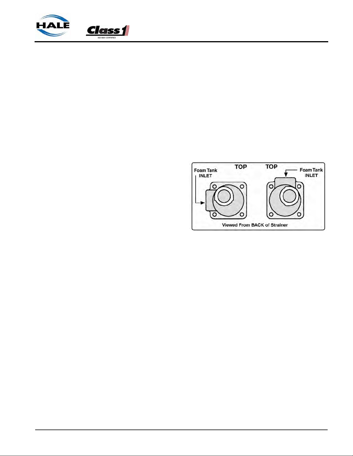
Installer Installation ❑
FS Series Strainer
When a pressurized water flush is provided to the strainer from one of the
discharges, Hale FS series strainers are required. The plumbing exposed
to the flush water pressure must be rated at or above the operating pressure
of all other discharge plumbing components (500 PSI/34 BAR minimum).
To Install FS Series Strainers
1. Choose a location on the apparatus that allows gravity feed from the
foam tank to the strainer inlet and from the strainer outlet to the foam
pump suction connection.
2. When selecting the
strainer location
make sure there is
sufficient space
behind the pump
panel to attach
hoses and fittings.
Also make sure the
inlet connection port
is oriented correctly. (See Figure
3-16: “FS Strainer
Orientation.”)
Figure 3-16: FS Strainer Orientation
3. Remove the strainer cap, mounting screws and nameplate from the
strainer assembly.
4. Mark holes for mounting the foam strainer by using the nameplate as a
guide, or see Figure 3-17: “FS Strainer Mounting Dimensions” on page
70.
5. Select the appropriate fittings to attach the hoses to the strainer. Two of
each fitting are included with the strainer assembly. The fittings and
hoses must be capable of withstanding the vacuum generated by the
foam pump (23 inches [584 mm] Hg) and the maximum flushing water
pressure (500 PSI [34 BAR]).
6. For FS-15 strainers use 3/4” (19mm) NPT x 3/4” hose fittings. For FS25 strainers use 1” (25mm) NPT x 1” hose fittings.
7. Coat all fitting threads with a suitable thread sealant. DO NO USE
Teflon Tape. Install the fittings into the strainer/valve assembly ends and
tighten.
FoamLogix 3.3 / 5.0 / 6.5 Installer / Operations Manual
p/n: 029-0021-68-0
69
Page 70

❑ Installer Installation
Figure 3-17: FS Strainer Mounting Dimensions
8. Make sure the strainer is properly oriented. (See Figure 3-16: “FS
Strainer Orientation.”) Apply Loctite #242 Threadlock Compound (or
equal) to the screws, then secure the strainer body and nameplate to
the apparatus. Install the strainer cap.
9. Install the clear plastic hose from the foam tank outlet to the inlet of the
strainer. (See Figure 3-14: “In-Line Strainer/Valve Installation,” on page
67.) Wet the ends of the hose and fittings to make the installation
easier.
CAUTION !
MAKE SURE THE FOAM TANK AND FOAM CONCENTRATE SUCTION HOSES
ARE CLEAN BEFORE MAKING FINAL CONNECTION TO FOAM PUMP. IF
NECESSARY FLUSH TANK AND HOSES PRIOR TO MAKING CONNECTION.
10. Install the clear plastic hose from the strainer outlet to the inlet of the
Hale FoamLogix foam pump, or the selector valve.
70
FoamLogix 3.3 / 5.0 / 6.5 Installer / Operations Manual
p/n: 029-0021-68-0
Page 71

Installer Installation ❑
Check Valve / Injector Fitting
The Hale check valve/
injector fitting, supplied
with the Hale FoamLogix
system, meets NFPA
requirements for a nonreturn device in the foam
injection system. It prevents back flow of water
into the foam concentrate
tank.
When properly installed
the brass and stainless
steel construction check
valve/injector fitting
ensures foam concentrate is injected into the
Figure 3-18: Check Valve/Injector Fitting
Orientation
center of the water flow for better mixing. (See Figure 3-18: “Check Valve/
Injector Fitting Orientation.”)
Note: Always position the check valve/injector fitting at a horizontal or higher
angle to allow water to drain away from the fitting. This avoids sediment deposits
or the formation of an ice plug.
The check valve/injector fitting must be
mounted in a location that is common
to all discharges which require foam
concentrate. (See Figure 3-19: “Check
Valve / Injector Fitting Installation.”)
The Hale FoamLogix system DOES
NOT permit a separate injection point
for each foam capable discharge.
The check valve/injector fitting has 1”
NPT (25.4mm) threads on the outside,
to fit into the 1” NPT threaded connection on the Hale mini manifold, a pipe
tee, or a 1” NPT weld fitting installed in
the discharge piping of the fire pump.
(See Figure 3-19: “Check Valve / Injector Fitting Installation.”)
The inlet connection of the check
Figure 3-19: Check Valve / Injector Fitting
Installation
valve/injector fitting uses a 1/2” (13mm) NPT female threads.
FoamLogix 3.3 / 5.0 / 6.5 Installer / Operations Manual
p/n: 029-0021-68-0
71
Page 72

❑ Installer Installation
Foam Concentrate Injection Hose
Connect a hose from the foam pump inject port to the inlet of the check
valve injector fitting. (See Figure 3-20: “Injection and Bypass Hose Connections.”)
Figure 3-20: Injection and Bypass Hose Connections
The hose and fittings from the INJECT port to the check valve injector fitting
should have a minimum 1/2” (13 mm) inside diameter and be rated at 500
PSI (34 BAR) working pressure (Aeroquip 2580-10 or equal).
Bypass Hose Connection
A bypass port is provided on the discharge side of the ADT, or a 1/4 turn
bypass valve is mounted on the discharge of the foam pump when the ADT
option is not installed. (See Figure 3-21: “Bypass Valve Assembly,” on page
73.)
The bypass handle must be accessible by the pump operator during normal
operations. (See Figure 3-20: “Injection and Bypass Hose Connections.”)
The bypass is a 3-way directional valve. Determine which port is the
INJECT port and which port is the BYPASS. (See Figure 3-21: “Bypass
Valve Assembly,” on page 73.)
Bypass hose connections are 1/2” (13mm). Hose fittings compatible with all
foam concentrates must be provided. The hose from the BYPASS port is
plumbed to the atmosphere and should not receive HIGH pressure.
72
FoamLogix 3.3 / 5.0 / 6.5 Installer / Operations Manual
p/n: 029-0021-68-0
Page 73

This hose is used for calibrating the foam pump, pumping
the concentrate into a container to empty the foam tank
or to assist in priming of the
foam pump. The hose from
the BYPASS port, must be
long enough to reach a container outside the truck.
Note: If the handle or placard
is removed from the bypass
valve for repairs or to facilitate
remote mounting make sure
they are installed on the valve
correctly. Make sure the tang
on the handle engages the
cast stops. (See Figure 3-21:
“Bypass Valve Assembly.”)
Installer Installation ❑
Figure 3-21: Bypass Valve Assembly
ADT Option Air Connections
If the ADT option is used, install the operating switch and indicator light
placard on the apparatus operator panel. A mounting cutout diagram is provided. (See Figure 3-22: “ADT Option Panel Placard Layout Dimensions.”)
After mounting the placard assembly install the air hoses from the ADT to
the placard assembly. Make sure proper connections are made at the placard assembly. (See Figure 3-23: “ADT Air Hose Connections, Part 1,” on
page 74.)
A color coded decal attached to the ADT valve assembly along with an
optional color coded air hose harness simplifies air hose connections. If the
optional air hose harness is not used, 1/4” (6mm) inside diameter air brake
tubing can be substituted. Make sure the air brake tubing selected has the
proper DOT approval.
(See Figure 3-23: “ADT Air Hose Connections, Part 1,” on page 74.) Also
see Figure 3-24: “ADT Option Air Hose Connections, Part 2” on page 75.
When cutting the air harness or air brake tubing to size make sure the ends
are square using a tubing cutter or razor knife.
FoamLogix 3.3 / 5.0 / 6.5 Installer / Operations Manual
p/n: 029-0021-68-0
73
Page 74

❑ Installer Installation
Figure 3-22: ADT Option
Panel Placard Layout
Dimensions
74
Figure 3-23: ADT Air Hose Connections, Part 1
FoamLogix 3.3 / 5.0 / 6.5 Installer / Operations Manual
p/n: 029-0021-68-0
Page 75

Installer Installation ❑
FoamLogix 3.3 / 5.0 / 6.5 Installer / Operations Manual
p/n: 029-0021-68-0
Figure 3-24: ADT Option Air Hose Connections, Part 2
75
Page 76

❑ Installer Installation
Notes
______________________________________________________________
______________________________________________________________
______________________________________________________________
______________________________________________________________
______________________________________________________________
______________________________________________________________
______________________________________________________________
______________________________________________________________
______________________________________________________________
______________________________________________________________
______________________________________________________________
______________________________________________________________
______________________________________________________________
______________________________________________________________
______________________________________________________________
______________________________________________________________
______________________________________________________________
______________________________________________________________
______________________________________________________________
______________________________________________________________
______________________________________________________________
______________________________________________________________
______________________________________________________________
______________________________________________________________
______________________________________________________________
______________________________________________________________
______________________________________________________________
______________________________________________________________
______________________________________________________________
______________________________________________________________
______________________________________________________________
______________________________________________________________
______________________________________________________________
76
FoamLogix 3.3 / 5.0 / 6.5 Installer / Operations Manual
p/n: 029-0021-68-0
Page 77

Plumbing Installation ❑
3.5 SYSTEM PLUMBING DIAGRAMS
The following pages contain sample Hale FoamLogix system plumbing diagrams for various system configurations. Due to variations in apparatus
configuration and individual component locations, the lengths of hoses and
piping is not provided. The material described and component sizes shown
provide optimum performance for a Hale FoamLogix system.
These diagrams are intended as guidelines to assist the system installer
with the selection of hoses and fittings along with the connections required.
FoamLogix 3.3 / 5.0 / 6.5 Installer / Operations Manual
p/n: 029-0021-68-0
77
Page 78

❑ Plumbing Installation
(For barb fitting sizes, see Figure
3-14: “In-Line Strainer/Valve
Installation” on page 67.)
78
Figure 3-25: Typical Single Foam Concentrate Tank
FoamLogix 3.3 / 5.0 / 6.5 Installer / Operations Manual
p/n: 029-0021-68-0
Page 79

(For barb fitting sizes, see Figure
3-14: “In-Line Strainer/Valve
Installation” on page 67.)
Plumbing Installation ❑
Figure 3-26: Typical Single Foam Tank with MST and In-Line Strainer/Valve Assembly
FoamLogix 3.3 / 5.0 / 6.5 Installer / Operations Manual
p/n: 029-0021-68-0
79
Page 80

❑ Plumbing Installation
80
Figure 3-27: Typical Single Foam Tank, with MST and FS Series Strainers
FoamLogix 3.3 / 5.0 / 6.5 Installer / Operations Manual
p/n: 029-0021-68-0
Page 81

(For barb fitting sizes, see Figure 3-14:
“In-Line Strainer/Valve Installation” on
page 67.)
Plumbing Installation ❑
Figure 3-28: Single Foam Tank with MST II and In-Line Strainer/Valve Assembly
FoamLogix 3.3 / 5.0 / 6.5 Installer / Operations Manual
p/n: 029-0021-68-0
81
Page 82

❑ Plumbing Installation
82
Figure 3-29: Typical Single Foam Tank with MST II and FS Series Strainers
FoamLogix 3.3 / 5.0 / 6.5 Installer / Operations Manual
p/n: 029-0021-68-0
Page 83

(For barb fitting sizes, see Figure
3-14: “In-Line Strainer/Valve
Installation” on page 67.)
Plumbing Installation ❑
(For barb fitting sizes, see Figure
3-1 4: “I n-Li ne St rai ner/V alv e
Installation” on page 67.)
Figure 3-30: Typical Single Foam Tank with ADT and In-Line Strainer/Valve Assemblies
FoamLogix 3.3 / 5.0 / 6.5 Installer / Operations Manual
p/n: 029-0021-68-0
83
Page 84

❑ Plumbing Installation
Figure 3-31: Typical Dual Foam Tanks, with ADT and FS Series Strainer Assemblies
84
FoamLogix 3.3 / 5.0 / 6.5 Installer / Operations Manual
p/n: 029-0021-68-0
Page 85

3.6 ELECTRICAL
See Figure 3-32: “Single Tank Electrical Harness Overview,” on page 87.
Also see Figure 3-33: “Dual Tank Electrical Harness Overview” on page 88.
Complete system electrical diagrams are provided at the end of this manual. Refer to these diagrams for proper installation of each of the electrical
components.
The Hale FoamLogix 3.3, 5.0 or 6.5 system is designed to be installed with
a minimum of electrical connections. Cables are provided with each Hale
FoamLogix system to make the flow sensor, control unit and motor distribution box connections.
The system installer must supply primary power wire, low tank level sensor
wire and flat braided ground straps.
Electrical Installation ❑
CAUTION !
❑ Review the “Safety” section of this manual, beginning on page 13,
in its entirety before proceeding with electrical connections.
❑ To prevent system damage or electrical shock the main power sup-
ply wire must be the last connection made to the Hale FoamLogix
motor distribution box. Also see heading “Hale Foam System Layout Drawings” on page 39.
❑ The cables provided with each Hale FoamLogix system contain
shielded assemblies.
NEVER attempt to shorten or lengthen these shielded cables.
If necessary order longer or shorter cables from Hale Products to
suit your particular installation.
❑ The cables are indexed so they connect to the correct receptacle
one way only. The cables shipped with each Hale FoamLogix system are tested at the factory with the specific unit. When making
cable connections DO NOT force mismatched connections as damage can result, causing improper system operation.
❑ The system can only perform when electrical connections are
sound.
Make sure each electrical connection is correct.
❑ Hale FoamLogix systems are designed for use on direct current,
negative (–) ground apparatus electrical systems only.
❑ Do not mount a radio transmitter or transmitter cables in direct or
close contact with the Hale FoamLogix unit.
FoamLogix 3.3 / 5.0 / 6.5 Installer / Operations Manual
p/n: 029-0021-68-0
85
Page 86

❑ Electrical Installation
❑ Before connecting the cables, inspect the O-ring seal in the female
connector. If the seal washer is missing or damaged, water can
enter the connector causing corrosio, resulting in possible system
failure.
❑ The ground strap must be a minimum of 1-1/4” (32mm) wide and no
longer than 18” (457mm).
A longer ground strap must be wider or a double thickness strap
must be used.
Make sure the ground strap is attached to the chassis frame.
Grounding to the body IS NOT acceptable.
❑ Always disconnect the power cable, ground straps, electrical wires
and cables from the control unit or other Hale FoamLogix equipment before electric arc welding at any point on the apparatus.
Failure to do so could result in a power surge through the unit that
could cause irreparable damage.
CAUTION ! - continued
❑ There are no user serviceable parts inside Hale FoamLogix system
electrical/electronic components. Opening of these components
(motor distribution box or control unit) voids the warranty.
86
FoamLogix 3.3 / 5.0 / 6.5 Installer / Operations Manual
p/n: 029-0021-68-0
Page 87

Electrical Installation ❑
Single and Dual Tank Electrical Harness Overview
FoamLogix 3.3 / 5.0 / 6.5 Installer / Operations Manual
p/n: 029-0021-68-0
Figure 3-32: Single Tank Electrical Harness Overview
87
Page 88

❑ Electrical Installation
88
Figure 3-33: Dual Tank Electrical Harness Overview
Control / Display Unit
The control/display unit mounts in the operator panel of the apparatus. The
display is secured with four #10 socket head screws. (See Figure 3-34:
“Control/Display Unit Mounting Dimensions” on page 89.)
The display requires a 7.00” (178mm) minimum clearance from the back of
the operator panel to allow proper cable connection. Once the control unit
is mounted on the operator panel, attach the 14 pin AMP connector on the
cable assembly to the back of the display. For harness overview, see Section 8 “ Drawing Package,” on page 155. Also see Figure 3-35: “Distribution
Box Connections” on page 90.
FoamLogix 3.3 / 5.0 / 6.5 Installer / Operations Manual
p/n: 029-0021-68-0
Page 89

Electrical Installation ❑
Notes: Ensure that the panel where the control unit is mounted has an adequate
ground. For stainless steel and vinyl coated panels a ground strap, 1/2” (13mm)
wide, must be attached from one of the four screws securing the control unit in
place to the frame of the fire truck to ensure adequate grounding.
Add a service loop to avoid strain on the wires or connectors during body
and frame flex. Also see Figure 3-36: “Extra Cable Storage” on page 92.
Control / Display Unit Connection
The main control cable harness connects to the 14-pin AMP connector or
pigtail on the back of the control unit. For harness overview, see Section 8 “
Drawing Package,” on page 155. Also see Figure 3-34: “Control/Display
Unit Mounting Dimensions” on page 89.
FoamLogix 3.3 / 5.0 / 6.5 Installer / Operations Manual
p/n: 029-0021-68-0
Figure 3-34: Control/Display Unit Mounting Dimensions
89
Page 90

❑ Electrical Installation
Figure 3-35: Distribution Box Connections
Distribution Box Ground / Primary Power
CAUTION !
CONNECT THE PRIMARY POSITIVE LEAD FROM THE TERMINAL BLOCK TO
THE MASTER SWITCH TERMINAL OR RELAY TERMINAL USING MINIMUM 4
AWG TYPE SGX (SAE J1127), CHEMICAL RESISTANT, BATTERY CABLE
AND PROTECT WITH WIRE LOOM.
PREVENT CORROSION OF POWER AND GROUND CONNECTIONS BY SEALING THESE CONNECTIONS WITH THE SILICONE SEALANT PROVIDED.
Ground Connection
Be sure the Hale FoamLogix system is grounded to the chassis. Use a
short length of wide flat ground strap, at least 1-1/4” (32mm) wide and less
than 18” (457 mm) long, to reduce the potential of RFI emitted by this
connection.
90
A stud is located on the mounting base, labeled NEG (-), to attach the chassis ground strap to the Hale FoamLogix system. (See Figure 3-35: “Distribution Box Connections” on page 90.)
FoamLogix 3.3 / 5.0 / 6.5 Installer / Operations Manual
p/n: 029-0021-68-0
Page 91

Electrical Installation ❑
When making the ground strap connections make sure lugs are soldered to
the strap ends for trouble free connections. Seal all connection against corrosion. When the length of the ground strap exceeds 18” (457mm) use a
wider strap or a double thick strap.
CAUTION !
DO NOT CONNECT THE MAIN POWER LEAD TO SMALL LEADS THAT ARE
SUPPLYING SOME OTHER DEVICE, SUCH AS A LIGHT BAR OR SIREN. THE
HALE FOAMLOGIX MODELS 3.3, 5.0 AND 6.5 REQUIRE 60 AMP MINIMUM
CURRENT.
Primary Power Supply Connection
Make sure adequate switched electrical power from the battery + terminal to
the battery connection stud on the motor distribution box is provided. (See
Table 3-2: “Primary Power Cable Sizes” on page 55.)
Use 4 AWG minimum type SGX (SAE J1127) battery cable directly to the
battery, battery switch or solenoids for cable runs up to 6’ (1.8 meters) long.
Longer wire runs may require larger battery cable for proper operation. DO
NOT connect power to the same connection as the pump primer.
Display Power Connection
Use 16 AWG minimum type SGX (SAE J1127) wire for the display power
and ground connections. Using the harness provided, Hale p/n: 513-027004-4:
❑ Connect the BLACK wire to a chassis ground stud
❑ Connect the RED wire to a minimum 5 AMP fused dedicated circuit. If a
dedicated circuit is not available, connect to a terminal that has LOW current load items, such as ENFO IV, governor and tank level gauge, etc.
❑ Connect this harness to connector C5 on the FoamLogix main harness.
RFI / EMI
A 100% electrically shielded main cable harness is provided with the Hale
FoamLogix system to eliminate the potential problem of RFI / EMI.
Proper installation of system components and cables, along with proper
grounding, limits radio interference caused by the Hale FoamLogix system.
Additionally, make sure radio cables and hardware are not located in the
immediate area where the FoamLogix system is mounted.
FoamLogix 3.3 / 5.0 / 6.5 Installer / Operations Manual
p/n: 029-0021-68-0
91
Page 92

❑ Electrical Installation
Proper installation of system components and cables, along with
proper grounding, limits radio interference caused by the Hale FoamLogix system. Additionally, make
sure radio cables and hardware are
not located in the immediate area
where the FoamLogix system is
mounted.
Making round coils of extra control
and flow sensor cables in the pump
compartment can act as an
antenna. While the control and
flow sensor cables cannot be shortened, various lengths of cable are available to minimize the “extra” cable in
the apparatus.
Figure 3-36: Extra Cable Storage
When routing control and flow sensor cables take care to avoid routing them
next to antenna wires, radio power lines and radio components. When
there is extra cable, double the cable back on itself and secure with plastic
wire ties in a flat bundle instead of making a round coil. (See Figure 3-36:
“Extra Cable Storage.”)
Make sure the flow sensor tee is grounded. If metal piping is used sufficient
grounding may be present. However, Victaulic joints, plastic pipe and rubber mounted pumps interfere with proper grounding and an additional
ground strap may be required. If necessary, connect a flat braided ground
strap at least 1/4” (7mm) wide from the flow sensor tee to the apparatus
frame to ensure proper grounding.
The #6-32 UNC screw that holds the spade terminal to the flow sensor tee
can be used to attach the ground strap to the tee. (See Figure 3-13: “Flow
Sensor/Saddle Clamp Installation” on page 65.)
Flow Sensor Connections
The control cable harness (connector C3) connects to the 3-pin connector
on the flow sensor. For cable harness overviews, see Section 9 “ 9 Plate
Drawings,” on page 170.
92
“Low Level Sensor” Installation (Foam Tank)
The foam low tank level sensor(s) must be installed and wired to monitor the
foam concentrate level. (See Figure 3-37: “Low Level Sensor Mounting
Options” on page 93.)
FoamLogix 3.3 / 5.0 / 6.5 Installer / Operations Manual
p/n: 029-0021-68-0
Page 93

FOAM TANK LOW LEVEL
SENSORS MUST BE USED
TO PROTECT THE HALE
FOAMLOGIX FROM DRY
RUNNING. FAILURE TO
USE LOW LEVEL SENSORS WITH THE HALE
FOAMLOGIX SYST EM
VOIDS THE WARRANTY.
Side Mount Installation
A side mount low tank level
sensor is used if the bottom of the foam tank is not
accessible.
Electrical Installation ❑
CAUTION !
Figure 3-37: Low Level Sensor Mounting Options
1. The sensor has
1/2” (13mm)
NPT threads. If
tank design and
construction
allows, the side
mount sensor is
threaded
directly into the
side of the tank
at the proper
height. (See
Figure 3-38:
“Side Mount
Sensor Location Dimensions.”)
Figure 3-38: Side Mount Sensor Location Dimensions
Also, the sensor can be mounted on the foam tank using a 1/2” x 1” (13
x 25mm) NPT bushing and a bulkhead fitting with 1” (25mm) FNPT
threads.
2. The center of the switch must be located at least 1-½ to 2 inches (38 to
51 mm) from the bottom of the foam tank with the float positioned on top
of the switch to allow up and down movement.
FoamLogix 3.3 / 5.0 / 6.5 Installer / Operations Manual
p/n: 029-0021-68-0
93
Page 94

❑ Electrical Installation
Note: When the side mount low level sensor senses a low concentrate condition
the system operates for an additional one minute unless the foam concentrate
level is restored. If the foam concentrate level is not restored the system SHUTS
DOWN. When locating the side mount low tank level sensor on the tank sufficient
foam concentrate should be present for one minute of operation at the rated flow.
3. Coat the threads of the sensor with a suitable sealant and insert into
tank fitting. Tighten sensor making sure the float is on the top of the
sensor. (See Figure 3-37: “Low Level Sensor Mounting Options” on
page 93.)
4. After installation, check operation of the side mount low tank level sensor with a powered test light. With no foam in the tank, the light should
be ON. If light does not illuminate, rotate the side mount low tank level
sensor until the test light is ON.
Bottom Mount Installation
The bottom mount foam tank low level sensor must be mounted into the bottom of the foam tank. (See Figure 3-37: “Low Level Sensor Mounting
Options” on page 93.)
1. The sensor, as supplied, is threaded into a bushing (1” [25mm] NPT
threads) and is designed to be installed from the outside of the foam
tank through a bulkhead fitting or boss with 1” (25mm) FNPT threads.
2. Mount the sensor in the bottom of the foam tank in an upright position.
Use a suitable sealant to prevent concentrate leakage. (See Figure 337: “Low Level Sensor Mounting Options” on page 93.)
3. Check low tank level sensor operation with a powered test light. With no
foam in the tank, the light should be ON.
4. If not, remove the clip from the end of the sensor. Remove float and
reinstall 180° out of position. Re-install clip.
Top Mount Installation
The top mount low level sensor assembly is available for installations where
the sides or bottom of the foam tank are not accessible or sensor service is
required without draining the foam tank.
94
The sensor assembly is flange mounted in an access hole at the top of the
foam tank. The two section telescoping assembly permits adjustment of the
low tank level sensor position for various foam tank depths, from 31- 1/2” to
60” (800mm to 1,524mm). (See Figure 3-39: “Top Mount Sensor Dimensions” on page 95.)
FoamLogix 3.3 / 5.0 / 6.5 Installer / Operations Manual
p/n: 029-0021-68-0
Page 95

Flange cutout dimensions are shown in
Figure 3-39: “Top
Mount Sensor Dimensions.” The flange
gasket can also be
used as a template to
mark hole location.
1. Layout and drill
holes in the top of
the foam tank.
(See Figure 3-39:
“Top Mount Sensor
Dimensions.”)
2. The center of the
sensor should be
located at least 11/2” to 2” (38 to
51mm) from the
sides of the foam
tank.
Electrical Installation ❑
Figure 3-39: Top Mount Sensor Dimensions
Note: The minimum depth of the foam tank for installation of the top mount sensor is 31-1/2” (800mm). If the tank depth is less than 31-1/2” (800mm) cut the
tubing accordingly. (See heading “Resizing the Top Mount Low Level Sensor” on
page 96.)
3. Determine the approximate length of the low tank sensor extension by
measuring from the top of the foam tank at the flange opening to the
bottom of the tank.
4. When properly installed the center of the sensor float should be 1-1/2”
to 2” (38 to 51mm) above the bottom of the foam tank.
5. Loosen the strain relief gland nut to allow the sensor wire to slide
through the strain relief.
6. Adjust the telescoping section until the desired length is achieved as
measured from the bottom of the flange to the bottom of the sensor.
Tighten the compression fittings on the union to lock length setting.
7. Tighten the strain relief around the sensor wire.
8. Inser t the sensor assembly through the 1.31” (33mm) hole and align the
screw holes on the flange and gasket with the holes on the tank.
Secure the assembly in place using four 1/4-20 UNC x 1” (25mm) long
cap screws, 1/4” (7mm) washers and lock washers.
FoamLogix 3.3 / 5.0 / 6.5 Installer / Operations Manual
p/n: 029-0021-68-0
95
Page 96

❑ Electrical Installation
USE MOUNT ING HARDWARE THAT IS COMPATIBLE WITH ALL FOAM CONCENTRATES BEING USED IN THE SYSTEM. USE WASHERS, LOCK WASHERS AND CAP SCREWS MADE OF BRASS OR 300 SERIES STAINLESS
STEEL.
Resizing the Top Mount Low Level Sensor
Certain applications may require the top mounted sensor to be shorter than
factory length. (See Figure 3-40: “Top Mount Low Level Sensor Assembly”
on page 97.)
To resize -
(See Figure 3-40: “Top Mount Low Level Sensor Assembly” on page 97.)
CAUTION !
1. Loosen and remove the strain relief gland nut and strain relief from the
top of the sensor assembly.
2. Loosen and remove the 1/4” (6mm) FNPT x 1/2” (13mm) tube compression fitting from the bottom of the assembly.
3. Slide the sensor assembly out from the bottom being careful not to damage the wiring as it is pulled from the assembly. DO NOT separate the
1/2” tube from the 5/8” tube.
4. Loosen the compression nut from the 1/2” (13mm) FNPT x 5/8” (16mm)
tube compression fitting at the top of the assembly.
5. Using a tubing cutter, remove an “equal” amount from the end of each
tube (5/8” and 1/2”). You must cut off the ferrule from both ends. Deburr
the cuts using a fine emery paper.
6. Install a new 1/2” (13mm) compression ferrule on the end of the 1/2”
O.D. tube. Carefully thread the sensor wire through the tube assembly.
7. Attach the 1/4” (6mm) FNPT x 1/2” (13mm) tube compression fitting,
with sensor attached, to the end of the tube.
8. Install and tighten the 1/2” compression nut.
9. Install a new 5/8” (16mm) compression ferrule on the end of the 5/8”
O.D. tube. Carefully thread the sensor wire through the flange and gasket assembly and install strain relief and strain relief gland nut. DO NOT
tighten.
96
FoamLogix 3.3 / 5.0 / 6.5 Installer / Operations Manual
p/n: 029-0021-68-0
Page 97

10. Install and
tighten the 5/
8” (16mm)
tube compression nut.
11. Slide the 1/2”
diameter tube
in the 5/8”
(16mm) diameter tube and
adjust the telescoping section until the
desired length
is achieved, as
measured
from the bottom of the
flange to the
bottom of the
sensor.
Tighten the
compression
fittings on the
union to lock
length setting.
Electrical Installation ❑
12. Tighten the
strain relief
gland nut and
strain relief.
Low Level Sensor Wiring
WHEN EXTENDING THE LOW TANK SENSOR WIRES MAKE SURE THE
SPLICES ARE PROPERLY SEALED USING AN ADHESIVE FILLED HEAT
SHRINK TUBING.
FoamLogix 3.3 / 5.0 / 6.5 Installer / Operations Manual
p/n: 029-0021-68-0
Figure 3-40: Top Mount Low Level Sensor Assembly
CAUTION !
97
Page 98

❑ Electrical Installation
Single Foam Tank System
For cable harness overviews, see Section 9 “ 9 Plate Drawings,” on page
170. Also see Figure 3-32: “Single Tank Electrical Harness Overview” on
page 87.
Use a minimum 16 AWG type SXL or GXL (SAE J1128) wire to extend the
low tank sensor wire to the 2-pin Packard WeatherPack connector C10 of
the main cable harness. Low tank level sensors are not polarity sensitive
therefore terminal connections are not specific.
When splicing wires make sure the splices are sealed using an adhesive
filled heat shrink tubing. Where two wires exit the heat shrink tubing pinch
the tubing while heating the it to make sure the adhesive seals around both
wires.
CAUTION !
USE THE SILICONE SEALER PROVIDED TO INSULATE AND PREVENT
CORROSION.
A connector kit (Hale p/n: 546-1780-00-0) is available that contains a Packard WeatherPack 2-contact shroud half, two (2) 14-16 gauge male terminals
and two (2) 14-16 gauge cable seals. Assemble these components to the
end of the low tank sensor wires.
Snap the two halves of the WeatherPack connector together making sure
they are sealed.
Note: If a Hale MST is not used, install the tank select jumper plug, Hale p/n:
513-0320-23-0, to connector C8. (See Figure 3-32: “Single Tank Electrical Harness Overview” on page 87.)
Dual Foam Tank System
For cable harness overviews, see Section 9 “ 9 Plate Drawings,” on page
170. Also see Figure 3-33: “Dual Tank Electrical Harness Overview” on
page 88.
98
CAUTION !
BEFORE RUNNING WIRES FROM THE LOW TANK SWITCHES TO THE MAIN
CABLE HARNESS MAKE SURE THE WIRES FROM TANK “A” ARE IDENTIFIED AND PROPERLY LABELED.
FoamLogix 3.3 / 5.0 / 6.5 Installer / Operations Manual
p/n: 029-0021-68-0
Page 99

Electrical Installation ❑
Use a minimum 16 AWG type SXL or GXL (SAE J1128) wire to extend the
low tank sensor wires to the 2-pin Packard WeatherPack the following connectors of the main cable harness:
❑ Tank “A” - C10
❑ Tank “B” - C11
Low tank level sensors are not polarity sensitive therefore terminal connections are not specific.
When splicing wires make sure the splices are sealed using an adhesive
filled heat shrink tubing. Where two wires exit the heat shrink tubing pinch
the tubing while heating the it to make sure the adhesive seals around both
wires.
CAUTION !
USE THE SILICONE SEALER PROVIDED TO INSULATE AND PREVENT
CORROSION.
A connector kit (Hale p/n: 546-1780-00-0) is available that contains a Packard WeatherPack 2-contact shroud half, two (2) 14-16 gauge male terminals
and two (2) 14-16 gauge cable seals. Assemble these components to the
end of the low tank sensor wires.
Snap the two halves of the WeatherPack connector together making sure
they are sealed.
Remote Activation Switch Option
(See Figure 3-41: “Remote Activation Switch Installation Dimensions” on
page 100.)
Choose a location in the apparatus personnel compartment for mounting
the remote activation switch. Make sure the switch is accessible to the
operator without interfering with other controls on the apparatus.
Install the remote activation switch as follows:
Cutout the panel and drill the four 0.203 inch (5mm) diameter through holes.
(See Figure 3-41: “Remote Activation Switch Installation Dimensions.”)
FoamLogix 3.3 / 5.0 / 6.5 Installer / Operations Manual
p/n: 029-0021-68-0
99
Page 100

❑ Electrical Installation
Figure 3-41: Remote Activation Switch Installation Dimensions
1. Insert switch assembly through the panel cutout and secure to using the
#10-24 UNC x 1/2” (13mm) screws and nuts provided.
Note: When making cable connections, make sure the cable is routed by the
shortest most direct route. A maximum of 40 feet (12 meters) of remote cable
may be used.
2. Connect the remote activation switch cable from the main cable harness
connector C2. (See Figure 3-32: “Single Tank Electrical Harness Overview” on page 87.) Also see Figure 3-33: “Dual Tank Electrical Harness
Overview” on page 88.
100
FoamLogix 3.3 / 5.0 / 6.5 Installer / Operations Manual
p/n: 029-0021-68-0
 Loading...