

Page 1

FoamLogix
TM
Model 2.1A and 1.7AHP Class “A”
Electronic Foam Proportioning Systems
Description, Installation and
Operation Manual
HALE PRODUCTS, INC / CLASS 1
607 NW 27th Avenue ● Ocala, FL 34475
U.S.A. Telephone: 352-629-5020
FAX: 800-533-3569
GODIVA LTD.
Charles Street ● Warwick, England CV34
5LR Phone: 44-1-926-623600
5LR Phone: 44-1-926-623600
IDEX DINGLEE TECHNOLOGY (Tianjin) Co. Ltd.
No.9, 2nd Haitai Fazhan Road Huayuan Industrial Development Area (outside of ring road)
Tianjin High-Tech Industrial Park Tianjin China
Telephone: 011-86-22-8568-9800
FAX: 011-862285689808
Manual p/n: 029-0020-74-0-F
Page 2

FoamLogix, Model 2.1A and 1.7AHP Class “A”
Electronic Foam Proportioning Systems
2
APPARATUS INFORMATION
Hale FoamLogix System Serial Number
In Service Date
Fire Department
Engine Number
Calibration Factors:
Water Flow Factor
Class A Foam Factor
NOTICE!
Hale Products does not assume responsibility for product failure resulting from improper maintenance or operation. Hale Products
is responsible only to the limits stated in the product warranty. Product specifications contained in this manual are subject to change
without notice.
All Hale products are quality components -- ruggedly designed, accurately machined, precision inspected, carefully assembled and
thoroughly tested. In order to maintain the high quality of your unit, and to keep it in a ready condition, it is important to follow the
instructions on care and operation. Proper use and good preventive maintenance will lengthen the life of your unit.
ALWAYS INCLUDE THE UNIT SERIAL NUMBER IN YOUR CORRESPONDENCE.
ECO NO
REV
CHANGED FROM
BY
DATE
APVD
03-110 A RELEASED FOR PRINTING
PRW
6/1/2003
MAL
03-215
B
UPDATED FOR DESIGN CHANGE
PRW
6/30/2003
MAL
04-236
C
UPDATE FOR DESIGN CHANGE
LWH
10/05/04
MAL
ECR 2743
D
UPDATE TO INCLUDE 1.7ahp
RLL
1/15/09
DC
E
CHANGE INFO ON FOAM FLOW SENSOR
REPLACEMENT
RLL
8/10/09
DC
F
UPDATED INFORMATION AND DRAWINGS
TO INCLUDE NEW MOTOR DRIVER
JDF
11/1/18
JLS
Manual P/N: 029-0020-74-0, Rev F
Page 3

FoamLogix, Model 2.1A and 1.7AHP Class “A”
Electronic Foam Proportioning Systems
3
HOW TO USE THIS MANUAL
This manual is divided into seven sections for clarity and ease of use. Each of the following manual sections
can be a stand alone section or can be used in conjunction with each other.
SECTION 1 SAFETY
This section must be carefully read, understood and adhered to strictly by all installer/builders, operators and
service personnel using the Hale FoamLogix 2.1A and 1.7AHP Foam Proportioning Systems. Do not use or
install the system until you have thoroughly read this section. Failure to comply could cause risk of serious
injury to yourself and others, or damage to the system.
SECTION 2 DESCRIPTION
Provides an introduction to the Hale foam proportioning system along with guidelines for designing and
ordering a complete system.
SECTION 3 INSTALLATION
Provides information to assist the OEM with installation and initial setup of Hale foam proportioning systems
on an apparatus.
SECTION 4 SETUP AND CALIBRATION
Is used by the installer and end user for start-up and calibration of the Hale foam proportioning system.
SECTION 5 OPERATION
Is primarily used by the apparatus user for proper operation and maintenance of the Hale foam proportioning
system.
SECTION 6 TROUBLESHOOTING
If a problem developes, see this section for troubleshooting procedures.
SECTION 7 PARTS IDENTIFICATION
Section 7 includes a parts breakdown of the most commonly used parts of the FoamLogix System.
Page 4

FoamLogix, Model 2.1A and 1.7AHP Class “A”
Electronic Foam Proportioning Systems
4
NOTES
Page 5

FoamLogix, Model 2.1A and 1.7AHP Class “A”
Electronic Foam Proportioning Systems
5
CONTENTS PAGE
HOW TO USE THIS MANUAL ........................................................................................3
SECTION 1 SAFETY .................................................................................................................................... 3
SECTION 2 DESCRIPTION .......................................................................................................................... 3
SECTION 3 INSTALLATION ............................................................................................................................... 3
SECTION 4 SETUP AND CALIBRATION .......................................................................................................... 3
SECTION 5 OPERATION ................................................................................................................................... 3
SECTION 6 TROUBLESHOOTING .............................................................................................................. 3
SECTION 7 PARTS IDENTIFICATION .............................................................................................................. 3
SECTION 1 SAFETY ..................................................................................................... 11
Guidelines ................................................................................................................................................... 11
SECTION 2 DESCRIPTION ........................................................................................... 15
Rotary Plunger Pump .................................................................................................................................. 15
Control Unit .................................................................................................................................................. 15
Water Flow Sensor ...................................................................................................................................... 15
Feed Back Sensor ....................................................................................................................................... 15
Low Pressure Strainer ................................................................................................................................. 16
Table 1: Maximum Foam Solution Flows .............................................................................................. 16
Ordering Information ................................................................................................................................... 16
HALE FOAM SYSTEM SPECIFICATIONS ...................................................................... 18
Figure 2: Foam Pump Installation Envelope Dimensions .................................................................... 19
SYSTEM CONFIGURATION ............................................................................................ 20
PACKAGE “A” ........................................................................................................................................... 20
PACKAGE “B” ........................................................................................................................................... 20
Figure 3: Typical Hale FoamLogix 2.1A and 1.7AHP System Layout .................................................... 21
Hale FoamLogix 2.1A Foam Proportioner System ...................................................................................... 22
Low Tank Level Sensor Options .................................................................................................................. 23
Flow Sensors ............................................................................................................................................... 24
Figure 4: Pipe Size vs. Flow Range ....................................................................................................... 24
Check Valve Manifolds, Flanges and Gaskets ............................................................................................ 25
Elbows and Mini-Manifolds ......................................................................................................................... 26
Remote Start Option .................................................................................................................................... 27
SECTION 3 INSTALLATION ................................................................................................ 29
Foam Pump and Motor Assembly ............................................................................................................... 29
Control Unit and Instruction/System Diagram Placard ................................................................................ 30
Installer Supplied Components ................................................................................................................... 30
Foam Concentrate Suction Hose ................................................................................................................ 30
Recommended Components .................................................................................................................. 30
Foam Concentrate Discharge Hose ............................................................................................................ 31
Recommended Components .................................................................................................................. 31
Foam Concentrate Bypass Hose ................................................................................................................ 31
Recommended Components .................................................................................................................. 31
Check Valves ............................................................................................................................................................. 31
Flushing Water Hose ................................................................................................................................... 32
Foam Discharge Drains ............................................................................................................................... 32
Freeze Protection ........................................................................................................................................ 32
Electrical Requirements .............................................................................................................................. 32
Figure 5: Recommended Relay Wiring Schematic ................................................................................ 33
Table 6: Recommended Primary Power Cable Sizes ............................................................................. 33
Foam Concentrate Tank ................................................................................................................................................ 33
Page 6

FoamLogix, Model 2.1A and 1.7AHP Class “A”
Electronic Foam Proportioning Systems
6
Contents -continued ....................................................................... Page
SECTION 3 INSTALLATION Continued
FOAM PUMP MOUNTING ........................................................................................................ 34
Figure 7: FoamLogix Pump Installation.................................................................................................. 34
PLUMBING INSTALLATION ............................................................................................................. 34
Figure 8: Base Plate Mounting Hole Locations ...................................................................................... 35
Water and Foam Solution Plumbing ............................................................................................................ 35
Check Valve Manifold .................................................................................................................................. 35
Figure 9: Check Valve Manifold Installation ........................................................................................... 36
Optional Hale Piping Components .............................................................................................................. 36
“Waterway” Check Valves ........................................................................................................................................ 36
Figure 10: Typical Midship Pump Installation ......................................................................................... 37
Figure 11: “Typical 4” Check Valve Installation, Midship Pump” ............................................................. 37
Flow Sensor ................................................................................................................................................ 38
Figure 12: Flow Sensor Tee Position Range .......................................................................................... 38
Table 13: Pipe Size vz. Minimum Straight Run ..................................................................................... 38
Figure 14: Typical Reduced Size Sensor Piping Arrangement .............................................................. 39
Figure 15: Flow Sensor Placement ........................................................................................................ 39
Saddle Clamp Installation............................................................................................................................ 39
Foam Pump Flush System .......................................................................................................................... 40
Figure 16: Flow Sensor/Saddle Clamp Installation ................................................................................ 40
FOAM CONCENTRATE PLUMBING. ......................................................................................................... 40
Foam Strainer Connection .......................................................................................................................... 40
Check Valve/Injector Fitting ......................................................................................................................... 41
Figure 17: Check Valve Injector Fitting Installation ................................................................................ 41
Figure 18: Injection and Bypass Hose Connections............................................................................... 42
Foam Concentrate Injection Hose ............................................................................................................... 42
Bypass Hose Connection ............................................................................................................................ 42
ELECTRICAL INSTALLATION ......................................................................................................... 43
Electrical Connections ................................................................................................................................. 43
Figure 19: Control Unit Mounting Dimension ......................................................................................... 44
Control Unit .................................................................................................................................................. 44
Display Unit Power and Ground Connections ............................................................................................. 44
Figure 20: Control Harness Connections ............................................................................................... 45
Figure 21: System Power and Ground Connections .............................................................................. 45
Motor Ground/Primary Power ..................................................................................................................... 46
Ground Connection ..................................................................................................................................... 46
Primary Power Supply Connection.............................................................................................................. 46
RFI/EMI ...............................................................................................................................................................
46
Figure 22: Extra Cable Storage .............................................................................................................. 47
Page 7

FoamLogix, Model 2.1A and 1.7AHP Class “A”
Electronic Foam Proportioning Systems
7
Contents -continued ................................................................... Page
START-UP CHECKLIST ................................ ................................ ................................ 48
Electrical ...................................................................................................................................................... 48
Liquid ........................................................................................................................................................... 48
Foam Pump ................................................................................................................................................. 48
SYSTEM INSTALLER START-UP ....................................................................................... 49
Initial System Power Check......................................................................................................................... 49
Initial System Check .................................................................................................................................... 49
Figure 23: Control Unit Ready Indication ............................................................................................... 49
Figure 24: Simulated Flow Display ......................................................................................................... 50
INSTALLATION AND DELIVERY CHECK LIST ................................ ............................ 51
Installation ................................................................................................................................................... 51
Delilvery ....................................................................................................................................................... 51
USER CALIBRATION ....................................................................................................... 53
Entering Passwords .................................................................................................................................... 53
Table 25: Password Sequence ............................................................................................................... 53
Restore Factory Defaults ............................................................................................................................. 53
Calibration ................................................................................................................................................... 53
Figure 26: Display - Password and Calibration Modes .......................................................................... 54
Figure 27: Display - Flow Sensor Calibration ......................................................................................... 54
Flow Sensor Calibration .............................................................................................................................. 54
Record Flow and Sensor Calibration Factors .............................................................................................. 55
Figure 28: Display - Flow Sensor Calibration Factor .............................................................................. 55
Figure 29: Display - Simulated Flow Calibration .................................................................................... 55
Simulated Flow ............................................................................................................................................ 55
Foam Concentrate injection Rate ................................................................................................................ 55
Foam Pump Feedback Calibration .............................................................................................................. 56
Figure 30: Display - Foam Concentrate Injection Rate Default Value ......................................................... 56
Figure 31: Display - Foam Pump Feedback Calibration......................................................................... 56
Figure 32: Foam Concentrate Collection ................................................................................................ 56
Record Foam Pump Feedback Calibration Factor ...................................................................................... 57
Exit and Save Calibration ............................................................................................................................ 57
Figure 33: Display - Foam Pump Feedback Calibration Factor ............................................................. 57
Figure 34: Display - Exit and Save Calibration ....................................................................................... 57
Relief Valve ................................................................................................................................................................ 58
English to Metric Units ................................................................................................................................. 58
Figure 35: Relief Valve ....................................................................................................................................... 58
To convert to Metric units: ........................................................................................................................... 58
SECTION 4 OPERATION ............................................................................................................. 59
Description ................................................................................................................................................... 59
Figure 36: Digital Display Control Unit Overview ................................................................................... 59
Display Information ...................................................................................................................................... 60
Control Unit Functions ................................................................................................................................. 60
Flow ............................................................................................................................................................. 60
Page 8

FoamLogix, Model 2.1A and 1.7AHP Class “A”
Electronic Foam Proportioning Systems
8
% Foam ....................................................................................................................................................... 60
Total Flow ................................................................................................................................................... 60
Figure 37: Display - Function Modes ..................................................................................................... 60
Bar graph ..................................................................................................................................................... 61
Reset Functions .......................................................................................................................................... 61
Foam Concentrate Injection Rate ................................................................................................................ 61
Warning Messages ...................................................................................................................................... 61
Low Foam Tank Level .................................................................................................................................. 62
Figure 38: Diaplay - Low Foam Tank Display ......................................................................................... 62
Priming Error ............................................................................................................................................... 62
High Ambient Temperature ............................................................................................................................... 62
Figure 39: Display - Priming Error .......................................................................................................... 62
Priming the Foam Pump ............................................................................................................................. 63
Figure 40: Display - High Temperature and Low Battery ........................................................................ 63
NORMAL OPERATION SUMMARY ......................................................................................... 64
SIMULATED FLOW OPERATION ............................................................................................. 66
Figure 41: Display - Simulated Flow Operation ..................................................................................... 66
Simulated flow sequence ............................................................................................................................ 66
To End Simulated Flow................................................................................................................................ 67
SECTION 5 MAINTENANCE ...................................................................................................69
Maintenance Procedures ............................................................................................................................ 69
Freeze Protection ........................................................................................................................................ 69
SECTION 6 TROUBLESHOOTING ........................................................................................71
User Diagnostics ......................................................................................................................................... 71
Figure 42: Distribution Box Overview ..................................................................................................... 71
System Overview ........................................................................................................................................ 72
Figure 43: FoamLogix 2.1A & 1.7AHP System Closed-Loop Flow Diagram ......................................... 72
Distribution Box ........................................................................................................................................... 72
Pump/Motor ................................................................................................................................................. 72
Bar Graph .................................................................................................................................................... 73
Summary ..................................................................................................................................................... 73
Problem Isolation......................................................................................................................................... 73
Troubleshooting charts ................................................................................................................................ 74
Chart 44: Hale FoamLogix System Troubleshooting Flow Diagram ................................................... 74
Contents -continued .................................................................................... Page
SECTION 7 ILLUSTRATED PARTS BREAKDOWN ................................................................76
General ...................................................................................................................................................................
76
Abbreviations ..........................................................................................................................................................
76
Foam Pump Assembly .................................................................................................................................... 78
Figure 7-1: Foam Pump Assembly ............................................................................................................. 79
Foam Flow Meter Assembly ............................................................................................................................ 80
Figure 7-2: Foam Flow Meter Assembly ................................................................................................ 81
Flow Sensor components ................................................................................................................................ 82
Figure 7-3: Flow Sensor Components........................................................................................................ 83
Page 9

FoamLogix, Model 2.1A and 1.7AHP Class “A”
Electronic Foam Proportioning Systems
9
ADDITIONAL FOAMLOGIX COMPONENTS .................................................................................................. 84
Figure 7-4: Additional FoamLogix Components. ........................................................................................ 85
Figure 7-5: Additional FoamLogix Components ......................................................................................... 85
FoamLogix 2.1A Pump Repair Kit. .................................................................................................................. 86
APPENDIX A
HALE FOAM CONCENTRATE COMPATIBILITY .....................................................................87
Table A-1: Hale Foam Concentrate Compatibility...................................................................................... 87
Reference .................................................................................................................................................. 88
Distribution Box Replacement - Required Checks ........................................................................89
Foam Flow Sensor Replacement Instructions ................................................................................93
Warranty ..............................................................................................................................................................
95
Page 10

FoamLogix, Model 2.1A and 1.7AHP Class “A”
Electronic Foam Proportioning Systems
10
Page 11

FoamLogix, Model 2.1A and 1.7AHP Class “A”
Electronic Foam Proportioning Systems
11
SECTION 1 SAFETY
IMPORTANT!
THE HALE “FOAMLOGIX™” MODELS 2.1A
AND 1.7AHP CLASS “A” ELECTRONIC FOAM
PROPORTIONING SYSTEMS ARE DESIGNED
FOR OPTIMUM SAFETY OF ITS OPERATORS
AND TO PROVIDE RELIABLE AND SAFE FOAM
CONCENTRATE INJECTION. FOR ADDED
PROTECTION AND BEFORE ATTEMPTING
INSTALLATION OR OPERATION PLEASE FOLLOW
THE SAFETY GUIDELINES LISTED IN THIS SECTION
AND ADHERE TO ALL WARNING, DANGER, CAUTION
AND IMPORTANT NOTES FOUND WITHIN THIS
GUIDE.
THIS SECTION ON SAFETY MUST BE CAREFULLY
READ, UNDERSTOOD AND ADHERED TO STRICTLY
BY ALL INSTALLERS AND OPERATORS BEFORE
ATTEMPTING TO INSTALL OR OPERATE THE
FOAMLOGIX PROPORTIONING SYSTEM.
WHEN DEVELOPING DEPARTMENTAL APPARATUS
OPERATING PROCEDURES, INCORPORATE THE
WARNINGS AND CAUTIONS AS WRITTEN.
FoamLogix is a trademark of Hale Products,
Incorporated. All other brand and product
names are the trademarks of their respective
holders.
GUIDELINES
READ ALL INSTRUCTIONS THOROUGHLY BEFORE
BEGINNING ANY INSTALLATION OR OPERATION
PROCESS.
❑ Installation should be performed by a trained
and qualified installer, or your authorized Hale
Products service representative.
❑ Be sure the installer has sufficient knowledge,
experience and the proper tools before
attempting any installation.
❑ Make sure proper personal protective equipment
is used when operating or servicing apparatus.
❑ A foam tank low level sensor must be utilized
to protect the Hale Foam proportioner from dry
running. Failure to use a low level sensor with
the Hale Foam system voids warranty.
❑ DO NOT permanently remove or alter any
guard or insulating devices, or attempt to
operate the system when these guards are
removed.
Make sure all access/service panels and
covers are installed, closed and latched tight,
where applicable.
❑ DO NOT remove or alter any hydraulic or
pneumatic connections, electrical devices,
etc. DO NOT tamper with or disconnect safety
features or modify protective guards (such
as covers or doors). DO NOT add or remove
structural parts. Doing so voids the warranty.
Any of the above could affect system capacity
and/or safe operation of the system and is
a serious safety violation which could cause
personal injury, could weaken the construction
of the system or could affect safe operation of
the FoamLogix Proportioning System.
WARNING!
NO MODIFICATIONS OR ADDITIONS MAY BE MADE
TO THE FOAMLOGIX PORPORTIONING SYSTEM
WITHOUT PRIOR WRITTEN PERMISSION FROM:
Hale Products, Incorporated
700 Spring Mill Avenue
Conshohocken, PA 19428
Telephone: 610-825-6300
Fax: 610-825-6440
❑ To prevent electrical shock always
disconnect the primary power source
before attempting to service any part of the
Hale Foam system.
Page 12

FoamLogix, Model 2.1A and 1.7AHP Class “A”
Electronic Foam Proportioning Systems
12
❑All electrical systems have the potential to
cause sparks during service. Take care to
eliminate explosive or hazardous environments
during service and/or repair.
❑To prevent system damage or electrical
shock the main power supply wire is the last
connection made to the Hale Foam proportioner
distribution box.
❑Release all pressure then drain all concentrate
and water from the system before servicing any
of its component parts.
❑Do not operate system at pressures higher than
the maximum rated pressure.
❑Use only pipe, hose, and fittings from the foam
pump outlet to the injector fitting, which are rated
at or above the maximum pressure rating at
which the water pump system operates.
❑Hale Foam proportioning systems are designed
for use on negative ground direct current
electrical systems only.
❑Do not mount radio transmitter or transmitter
cables in direct or close contact with the
FoamLogix control unit.
❑Before connecting the cord sets and wiring
harnesses, inspect the seal washer in the female
connector. If the seal washer is missing or
damaged, water can enter the connector causing
corrosion of the pins and terminals. This could
resulting in possible system failure.
❑Always disconnect the power cable, ground
straps, electrical wires and control cables from
the control unit or other Hale Foam system
equipment before electric arc welding at any
point on the apparatus Failure to do so could
result in a power surge through the unit that
could cause irreparable damage.
❑DO NOT connect the main power lead to small
leads that are supplying some other device, such
as a light bar or siren.
The Hale FoamLogix, Models 2.1A and
1.7AHP require 40 AMP minimum current.
❑When operating the Hale FoamLogix in
Simulated Flow mode, an outlet for the foam
concentrate must be provided to prevent
excessive pressure buildup in the discharge
piping or hoses.
❑Make sure the foam tank and foam concentrate
suction hoses are clean before making final
connection to foam pump. If necessary flush
tank and hoses prior to making connection.
❑Check all hoses for weak or worn conditions
after each use. Ensure that all connections and
fittings are tight and secure.
❑Ensure that the electrical source of power for
the unit is a negative (–) ground DC system, of
correct input voltage, with a reserve minimum
current available to drive the system.
❑The in-line strainer/valve assembly is a low
pressure device and WILL NOT withstand
flushing water pressure in excess of 45 PSI (3
BAR).
❑When determining the location of Hale Foam
system components keep in mind piping runs,
cable routing and other interferences that
could hinder or interfere with proper system
performance.
❑Always position the check valve/injector fitting
at a horizontal or higher angle to allow water
to drain away from the fitting. This avoids the
possibility of sediment deposits or the formation
of an ice plug.
❑The cord sets provided with each Hale Foam
system are indexed to ensure correct receptacle
installation (they insert one way only). When
making cord set connections DO NOT force
mismatched connections as damage can result
in improper system operation.
❑Make sure all connections are sound, and that
each connection is correct.
❑The cables shipped with each Hale Foam
system are 100% tested at the factory with that
unit. Improper handling and forcing connections
can damage these cables which could result in
other system damage.
Page 13

FoamLogix, Model 2.1A and 1.7AHP Class “A”
Electronic Foam Proportioning Systems
13
❑There are no user serviceable parts inside Hale
Foam system electrical/electronic components.
Opening of the distribution box or control unit
voids the warranty.
❑Use mounting hardware that is compatible with
all foam concentrates to be used in the system.
Use washers, lock washers and cap screws
made of brass or 300 series stainless steel.
❑When making wire splice connections, make
sure they are properly insulated and sealed using
an adhesive filled heat shrink tubing.
❑ALWAYS connect the primary positive power
lead from the terminal block to the master switch
terminal or the positive battery terminal.
Use a minimum 8 AWG type SGX (SAE J1127)
chemical resistant battery cable and protect with
wire loom.
❑ Prevent corrosion of power and ground
connections by sealing these connections with
silicone sealant provided.
❑ Prevent possible short circuit by using the rubber
boot provided to insulate the primary power
connection at the Hale FoamLogix distribution
box.
Page 14

FoamLogix, Model 2.1A and 1.7AHP Class “A”
Electronic Foam Proportioning Systems
14
NOTES
Page 15

FoamLogix, Model 2.1A and 1.7AHP Class “A”
Electronic Foam Proportioning Systems
15
SECTION 2 DESCRIPTION
The Hale FoamLogix 2.1A and 1.7AHP Foam
Proportioning Systems are completely engineered,
factory matched foam proportioning systems that
provides reliable, consistent foam concentrate
injection for Class “A” foam operations.
Hale FoamLogix Foam systems accurately deliver
from 0.1% to 10.0% (up to the capacity of the foam
pump) foam concentrate through a check valve/
injector fitting, directly into the water discharge
stream. It is then fed as foam solution into a
standard fog nozzle, an air aspirated nozzle, or
CAFS equipment, through the apparatus discharge
piping. A properly configured and installed foam
system with Hale recommended components
virtually eliminates contamination of the booster
tank, fire pump and relief valve with foam
concentrate.
ROTARY PLUNGER PUMP
The heart of the Hale FoamLogix 2.1A and 1.7AHP
systems are an electric motor driven rotary plunger
pump. The pump is constructed of anodized
aluminum and stainless steel and is compatible
with most Class “A” foam concentrates. The pump
is close coupled to the electric motor thereby
eliminating maintenance of an oil filled gearbox.
A relief valve mounted on the foam pump and
constructed of brass, protects the foam pump
and foam concentrate discharge hoses from over
pressurization and damage.
CONTROL UNIT
The control unit, mounted on the operator panel, is
the single control point for the FoamLogix system.
Pressing the ON button starts foam concentrate
injection. A super bright digital LED display shows
the:
❑ Water flow rate
❑ Total water flow
❑ Foam concentrate injection percentage
❑ Total foam concentrate used, depending on the
display mode selected.
A bar graph indicates the approximate system
capacity being used. Adjustment of the foam
concentrate injection rate is accomplished by
pressing the appropriate button.
The control unit display also warns the operator if
errors or abnormal operations occur in the system,
such as low foam level.
WATER FLOW SENSOR
Foam concentrate injection rate is controlled by
a computer chip in the control unit for accurate,
repeatable, reliable foam concentrate injection. A
water flow sensor constantly monitors water flow
through the discharge piping. The information from
the flow sensor is provided to the control unit by
a shielded cable. When the FoamLogix system is
activated at the control unit a signal is sent through
the control cable to the distribution box to begin
foam concentrate injection. The distribution box then
provides power to the electric motor. As the motor
rotates the pump, foam concentrate flows through
the foam pump discharge to the one piece check
valve/ injector fitting into the water discharge stream.
Note: All Hale FoamLogix Foam systems
require a flow sensor for operation.
FEED BACK SENSOR
A feedback sensor in the foam pump discharge
measures foam concentrate flow. The water flow
rate and foam concentrate flow rate are constantly
compared by the computer chip in the control unit.
Page 16

FoamLogix, Model 2.1A and 1.7AHP Class “A”
Electronic Foam Proportioning Systems
16
The motor speed is constantly adjusted to maintain
the operator selected foam concentrate injection
rate. Since the system is flow based, injection rate
remains constant regardless of changes in system
pressure or the number of discharges that are open
(within the limits of the sytem).
The maximum rated foam concentrate flow, in
gallons per minute, is denoted by the model
number. Table 1: “Maximum Foam Solution Flows”
shows the system capacity at various foam
concentrate injection rates for the Hale FoamLogix
2.1A and 1.7APH units.
Table 1: Maximum Foam Solution Flows
The Hale FoamLogix 2.1A & 1.7A Foam system
configuration is shown in Figure 2-3: “Typical
System Layout” on page 21.
LOW PRESSURE STRAINER
A low pressure foam concentrate strainer is mounted
at the inlet of the foam pump. The strainer protects
the pump from debris that might accumulate in the
foam concentrate tank. The strainer/valve assembly
has a composite nonmetallic housing with stainless
steel mesh strainer element and includes a service
shut-off valve.
The valve inlet offers 1/2” NPT (13 mm) threads,
with a fitting to connect a 1/2” (13 mm) ID foam
concentrate suction hose.
The strainer and valve are low pressure devices
and are designed for installations where the
strainer IS NOT subject to HIGH pressure flushing
water.
ORDERING INFORMATION
Ordering Hale FoamLogix 2.1A and 1.7AHP
Foam Systems is simple. Using the current Hale
FoamLogix 2.1A Foam System Price List and
Order Form helps ensure a complete matched
system is provided to the end user.
Use the following procedure when ordering a
Hale FoamLogix 2.1A Foam system. Following
all steps to ensure that a complete system is
ordered:
1.
Check Hale Foam system product information update (Bulletin #961) for the latest
information and advice for foam system
selection.
2.
Determine the Class “A” foam concentrate
to be used in the system and ensure system
compatibility by referring to the Hale Foam
Concentrate Compatibility list (Bulletin #650).
3.
Consult the current Hale FoamLogix 2.1A/
1.7AHP Price List and Order Form for
ordering of the system.
The Hale FoamLogix 2.1A and 1.7AHP can be
ordered as one of two pre-configured packages
that include the pump and motor assembly,
control unit, flow sensor cable, stainless steel
check valve and injection manifold, and an
installation kit.
Package “A” includes the single check
valve manifold.
Maximum Foam Solution Flow
Injection Rate
Percent (%)
Gallons per
Minute (GPM)
Liters Per Minute
(LPM)
2.1A
1.7AHP
2.1A
1.7AHP
0.1
2,100
1,700
7,949
6,426
0.2
1,050
850
3,974
3,213
0.3
700
567
2,650
2,143
0.5
420
340
1,590
1,285
1.0
210
170
795
643
Page 17

FoamLogix, Model 2.1A and 1.7AHP Class “A”
Electronic Foam Proportioning Systems
17
Package “B” includes dual check valve
manifold.
Note: If package “A” is selected an additional check valve
is required where the foam manifold attaches to the pump
discharge for NFPA compliance.
4.
The Hale FoamLogix 2.1A and 1.7AHP may also
be ordered “a-la-carte” if one of the standard
packages does not meet end user requirements.
When ordering the system “a-la-carte” for a
complete system the Pump and motor assembly,
flow sensor, flow sensor cable, low tank sensor
and check valve injector fitting must be ordered
as a minimum.
Ordering the components as a complete system
allows Hale to configure and test the complete
order, to ensure a problem-free system.
5.
Additional Hale components available to
enhance system operation and ease installation
include:
❑ Control Cable Extension
❑ Waterway Check Valves
❑ Manifolds
❑ Flanges
System components are shown in the following
heading “System Configuration,” beginning on
page 20.
All components listed are engineered and tested
with Hale Foam systems to provide optimum system
performance. Using the information provided in this
manual and the detailed ordering procedures on
the option order form ensures that a complete Hale
Foam system is ordered thus eliminating delays
caused by missing components.
Page 18

FoamLogix, Model 2.1A and 1.7AHP Class “A”
Electronic Foam Proportioning Systems
18
HALE FOAM SYSTEM SPECIFICATIONS
2.1A
1.7AHP
Foam Pump
Dual Plunger
Dual Plunger
Maximum Foam Concentrate Output
2.1 GPM (8 LPM)
1.7 GPM (6.5 LPM)
Maximum System Operating Pressure
250 PSI (17 BAR)
400 PSI (27.5 BAR)
Maximum Operating Temperature
160o F (71o C)
160o F (71o C)
Pump Motor
0.44 HP (0.3 Kw), 12 VDC
0.44 HP (0.3 Kw), 12
VDC
Operating Ampere Draw
25 AMPS @ 12 VDC
30 AMPS @ 12 VDC
Maximum Ampere Draw
40 AMPS @ 12 VDC
40 AMPS @ 12 VDC
Page 19

FoamLogix, Model 2.1A and 1.7AHP Class “A”
Electronic Foam Proportioning Systems
19
Figure 2: Foam Pump Installation Envelope Dimensions
Page 20

FoamLogix, Model 2.1A and 1.7AHP Class “A”
Electronic Foam Proportioning Systems
20
SYSTEM CONFIGURATION
Package A
Part Number: (Choose One)
FLX21-12-1-10-1 (2.1A 12 Volt) FLX17-12-1-10-1 (1.7AHP 12 Volt)
FLX21-24-1-10-1 (2.1A 24 Volt) FLX17-24-1-10-1 (1.7AHP 24 Volt)
Description: FoamLogix Kit with single stainless steel check valve manifold
Includes the following:
(1) FoamLogix full function digital display control that displays flow, foam %, total flow and total foam
(1) Foam pump assembly with bypass and strainer service valves
(1) 15 feet of cable between display and pump and 10 feet of cable between display and flow sensor
(1) Compact foam manifold assembly with a single waterway check valve, flow sensor and foam
injection check valve installed. 3 inch grooved victaulic connections
Flow range 30 - 750 GPM
Note: A second check valve is recommended to avoid pump/water tank contamination.
(1) Installation kit includes clear reinforced foam inlet hose, hose clamps, positive and ground
terminal insulation kit
(2) Operation and Installation manuals
(1) Single tank system instruction placard
(1) Side mount low level tank sensor
Package B
Part Number: (Choose One)
FLX21-12-2-10-1 (2.1A 12 Volt) FLX17-12-2-10-1 (1.7AHP 12 Volt)
FLX21-24-2-10-1 (2.1A 24 Volt) FLX17-24-2-10-1 (1.7 AHP 24 Volt)
Description: FoamLogix Kit with dual stainless steel valve manifold (recommended for NFPA backflow
prevention compliance):
Includes the following:
(1) FoamLogix full function digital display control that displays flow, foam %, total flow and total foam
(1) Foam pump assembly with bypass and strainer service valves
(1) 15 feet of cable between display and pump and 10 feet of cable between display and flow sensor
(1) Foam manifold assembly with dual waterway check valves, flow sensor and foam injection check
valve installed. 3 inch grooved Victaulic connections
Flow range 30 - 750 GPM
(1) Installation kit includes clear reinforced foam inlet hose, hose clamps, positive and ground terminal
insulation kit
(2) Operation and Installation manuals
(1) Single tank system instruction placard
(1) Side mount low level tank sensor
Page 21

FoamLogix, Model 2.1A and 1.7AHP Class “A”
Electronic Foam Proportioning Systems
21
(Supplied
by system
installer)
Double Check
Valve Assembly
Figure 3: Typical Hale FoamLogix 2.1A and 1.7AHP System Layouts
(Also see Figure 20: “Control Harness Connections” on page 45)
Page 22

FoamLogix, Model 2.1A and 1.7AHP Class “A”
Electronic Foam Proportioning Systems
22
Hale FoamLogix 2.1A and 1.7AHP Foam Proportioner Systems
All Hale FoamLogix 2.1A and 1.7AHP systems include: Foam Pump/Motor Assembly and Control Unit
FoamLogix Base Unit,
Foam Pump/Motor Assembly
2.1A - 12V: 115498
2.1A - 24V: 115499
1.7AHP - 12V: 119276
1.7AHP - 24V: 119277
Control Display Unit p/n: 111530
Check Valve/Injector Fitting
p/n: 038-1790-00-0
Page 23

FoamLogix, Model 2.1A and 1.7AHP Class “A”
Electronic Foam Proportioning Systems
23
Bottom Mount Low Level Tank Sensor
Top Mount Low Level Tank Sensor
Low Tank Level Sensor Options
One Low Tank Level Sensor is Required
p/n: 200-2100-04-0
(1” NPT threaded bushing to mount from outside
foam tank.)
p/n: 200-2110-06-0
(Extends from 2-1/2’ to 5’ (0.8 to 1.5 meters) - may
be cut shorter if required.)
Page 24

FoamLogix, Model 2.1A and 1.7AHP Class “A”
Electronic Foam Proportioning Systems
24
1
A
20"
1'
B
Flow Sensors
Each Hale foam system requires a flow sensor for operation. Pipe size must be selected based on the
minimum and maximum water flow in the foam capable discharge. Following is a list of pipe size and rated flow
ranges, along with flow sensor saddle clamp part number. In all instances, a weld fitting may be substituted for
the saddle clamp.
Pipe Size
Flow Range
GPM
LPM
1.5”
10 - 350
38- 1,219
2”
20 - 550
76 - 2,082
2.5”
30 - 800
114 - 3,028
3”
50 - 1,250
189 - 4,731
4”
75 - 1,800
284 - 6,813
SCV or DCV
30 - 750
114 - 2,839
Figure 4: Pipe Size vs. Flow Range
Flow Sensor Paddle Wheel
p/n: 102714
Flow Sensor Saddle Clamp
Threads (NPT) Part Number
2” – p/n: 4842010
2.5” – p/n: 4843010
3” – p/n: 4844010
4” – p/n: 4846010
Flow Sensor Weld Fitting
Stainless Steel, p/n: 082-3060-00-0
Steel, p/n: 309020
Aluminium, p/n: 309010
Flow Sensor Cable
Dimension A & B
Part Number
10’ x 14’
(3.05m x 4.27m)
113438
15’ x 19’
(4.57m x 5.79m)
113439
Page 25

FoamLogix, Model 2.1A and 1.7AHP Class “A”
Electronic Foam Proportioning Systems
25
p/n 038-1570-08-0
Page 26

FoamLogix, Model 2.1A and 1.7AHP Class "A"
Electronic Foam Proportioning
Systems
26
HALE
Classf
Elbows and Mini-Manifolds
Close Fit Flanged Elbow
p/n:
098-0140-00-0
(115 flange inlet with 3" Victaulic outlet)
Close Fit Flanged Elbow
p/n:
098-0190-00-0
24330 flange inlet with 3• NPT female
and 4" Victaulic outlet)
Close Fit Flanged Elbow
pin:
098-0050-00-0
(115 flange inlet with 2.5" NPT female outlet)
Close Fit Flanged Elbow
p/n:
098-0020-00-0
(115 flange inlet with 115 flange outlet)
Mini-Manifold p/n:
178-0320-02-0
Page 27

FoamLogix, Model 2.1A and 1.7AHP Class “A”
Electronic Foam Proportioning Systems
27
Remote Start Option
Switch
p/n: 513-0330-01-0
Remote Start Option
Harness
p/n: 513-0680-00-0
(5m)
Page 28

FoamLogix, Model 2.1A and 1.7AHP Class “A”
Electronic Foam Proportioning Systems
28
NOTES
Page 29

FoamLogix, Model 2.1A and 1.7AHP Class “A”
Electronic Foam Proportioning Systems
29
SECTION 3 INSTALLATION
To simplify installation selection, one of the two
packages described in previous Section 2 should
be ordered. While either package provides most
of the components required for installation, the
following guidelines are offered to assist the system
installer with a complete system installation.
Carefully review the procedures that follow to
ensure the system is properly designed. This
section lists components that have been tested
with Hale FoamLogix and provide the best
system performance. Use of the recommended
materials and specified parts ensures a virtually
maintenance free installation.
Differences in apparatus plumbing and foam
system configuration make it impractical to show
exactly how the Hale FoamLogix 2.1A and 1.7AHP
systems are installed on a particular apparatus.
The information contained in this section, however,
applies to most situations and should be used
when designing and installing Hale FoamLogix
2.1A and 1.7AHP systems. A system plumbing and
electrical diagram is provided at the end of this
section to assist with installation.
Before proceeding with system installation,
carefully review the procedures that follow to
ensure the system is properly designed.
The Hale FoamLogix system is supplied with five
major components that must be located on the
apparatus.
❑ Foam pump and motor assembly
❑ Control unit
❑ Instruction/system diagram placard
❑ Flow Sensor
❑ Check valve injector fitting
Notes: The flow sensor and check valve
injector fitting may be pre-mounted, if a
manifold or pre-configured package is
ordered.
Optional components that require mounting on
the apparatus include:
❑ Mini Manifold
❑ Flanged elbows
IMPORTANT !
WHEN DETERMINING THE LOCATIONS OF HALE
FOAMLOGIX COMPONENTS BEING INSTALLED
KEEP IN MIND PIPING RUNS, CABLE ROUTING
AND OTHER INTERFERENCES THAT COULD
HINDER OR INTERFERE WITH PROPER SYSTEM
PERFORMANCE.
FOAM PUMP AND MOTOR ASSEMBLY
The foam pump and motor assembly must be
located in an area that is protected from road
debris and excessive heat buildup. The back of a
compartment or a compartment shelf is often an
ideal location. The foam system, bypass valve,
strainer and shut-off valve are located on the foam
pump and motor assembly and access to these
components must be provided.
The foam pump and motor assembly must be
mounted below the discharge of the foam tank to
provide for gravity feed to the foam pump. The foam
tank must be located where refilling can be easily
accomplished with 5 gallon (19 liters) pails and other
methods suitable to the end user. Most water tank
manufacturers build the foam tank into the booster
tank.
When specifying a foam tank, make sure provisions are made for:
❑ Installation of the low tank level sensor
Page 30

FoamLogix, Model 2.1A and 1.7AHP Class “A”
Electronic Foam Proportioning Systems
30
❑ Foam suction connections
❑ Tank drainage
❑ Proper fill openings, per NFPA requirements.
In addition, a foam tank refill system may
be required. See Hale EZFill system for
installation requirements.
CONTROL UNIT AND INSTRUCTION/
SYSTEM DIAGRAM PLACARD
Determine a location on the operator panel of the
apparatus for the control unit and instruction/ system
diagram placard, if provided. These components
must be located at the main pump operator position
in close proximity to each other. Consideration
must be given for routing the control cable from the
control unit to the distribution box on the foam pump
and motor assembly. If necessary, order longer
or shorter cable assemblies to suit the location
demands.
INSTALLER SUPPLIED COMPONENTS
Due to the many differences in apparatus configurations and design requirements the Hale
FoamLogix system installer must supply components, such as,
❑ mounting brackets
❑ piping
❑ hoses
❑ fittings
❑ electrical wiring
❑ foam tank(s)
The following guidelines are recommendations for
selection of additional components for a complete
system installation. These recommendations
reflect materials and components that are tested
extensively with Hale FoamLogix systems and
provide proven reliable performance.
Foam Concentrate Suction Hose
The Hale FoamLogix 2.1A and 1.7 AHP Foam
systems are provided with 15’ (4.6 meters) of 1/2”
(13mm) ID reinforced PVC foam concentrate suction
hose. The system installer may need to supply
additional fittings and hose from the foam tank to the
inlet of the foam pump.
All components selected transfer foam concentrate,
therefore they must be compatible with the foam
concentrates being used in the system. Hoses for
Class A foam concentrates have minimum 1/2”
(13mm) inside diameter.
Hoses for the foam concentrate suction must have
a rating of 23” (584 mm) Hg vacuum and 50 PSI
(3.5 BAR) pressure or greater.
Note: NFPA requires that foam concentrate suction
hose be clear to observe foam concentrate flow
during foam pump operation.
Recommended Components
❑Hose: PVC, Kuriyama Kuri-Tec K3130 or K7130
series
❑Fittings: Hose Barb Type; Brass, Stainless
Steel or Nylon
A tee with foam tank shut-off valve and a drain
valve is recommended in the foam tank suction
hose to allow, tank drainage and easier priming.
These components are subject to the same material
characteristics and pressure ratings as stated
above.
The foam concentrate strainer includes a shutoff valve. This valve is used to shut off foam
concentrate flow to service the strainer.
Page 31

FoamLogix, Model 2.1A and 1.7AHP Class “A”
Electronic Foam Proportioning Systems
31
Foam Concentrate Discharge Hose
The system installer must supply fittings and hoses
from the foam pump inject connection to the check
valve/injector fitting inlet. All components selected
transfer foam concentrate, therefore they must be
compatible with the foam concentrates being used
in the system.
The foam pump discharge connection is a 1/2” (13
mm) compression fitting. The check valve injector
fitting connection has 1/2” NPT threads. Hoses and
fittings of 1/2” minimum diameter rated at 500 PSI
(34.5 BAR) working pressure or maximum discharge
pressure of the fire pump must be used. Fittings and
hoses must be compatible with all foam agents to be
used.
Recommended Components
❑ Hose: Aeroquip 2580-8 or Equivalent
Reinforced Hydraulic Hose.
❑ Fittings: Brass or Stainless Steel Hose End
Crimp or Reusable Type (Aeroquip 412-9-8 or
Equivalent)
Foam Concentrate Bypass Hose
The foam concentrate bypass hose connection is
a 1/2” (13mm) hose barb connection. Hoses and
fittings of nominal 1/2” diameter must be used as
bypass hose. Since the bypass hose is used for
calibration and draining the system it does not see
high operating pressures; therefore, a hose with a
lower pressure rating than the inject hose may be
used.
Fittings and hoses used must be compatible
with all foam agents expected to be used. Use
fittings made of brass or 300 series stainless steel
compatible with all foam concentrates.
Recommended Components
❑ Hose: Low Pressure Hydraulic Hose or Air
Brake Tubing
❑ Fittings: Brass or Stainless Steel
It is recommended that the foam concentrate
bypass hose be long enough to extend past the
apparatus running board to reach five (5) gallon
(19 liter) containers, making foam pump setup and
calibration simpler.
Check Valves
Check valves must be installed on the apparatus
with foam systems to prevent contamination of the
foam concentrate with water and contamination
of the fresh water tank with foam. (See Figure 3:
“Typical Hale Foam-Logix 2.1A and 1.7AHP System
Layout” on page 21.)
When a Hale FoamLogix 2.1A and 1.7AHP foam
injection systems and related components are
properly installed the required check valves are
integral parts of the system.
NFPA standards require a check valve in the foam
concentrate injection line at the injection point. The
Hale p/n: 038-1790-00-0 Integral Check Valve/
Injector Fitting, a standard component included with
the Hale FoamLogix 2.1A and 1.7AHP systems and
installed when a manifold kit is ordered, meets these
requirements and threads directly into the foam
injection port on Hale manifolds.
Check valves must be installed in all water piping
locations where foam concentrate could drain
back into pumps or other components of the fire
apparatus.
As a minimum one check valve must be installed
where the water piping that supplies foam solution
connects to the fire pump discharge. To more
effectively keep foam contamination out of the fire
pump and water tank, double check valves are
recommended.
Page 32

FoamLogix, Model 2.1A and 1.7AHP Class “A”
Electronic Foam Proportioning Systems
32
Separate two check valves by at least 6” to 8” (152
to 203mm) of piping to form a dead zone between
the check valves. Individual drain lines should be
used on each check valve. The waterway check
valves must be rated for 500 PSIG (34.5 BAR) test
pressure.
Flushing Water Hose
If a Hale and USFS approved Class “A” foam
concentrate is used, flushing of the Hale FoamLogix
2.1A and 1.7AHP systems is not necessary as long
as the system is used periodically.
If a flushing water hose is required to flush the
foam pump, it must have a pressure reducer/
regulator that limits the flush water pressure to
25 to 50 PSI (2 to 4 BAR). The tubing and fittings
used must be compatible with foam concentrates
being used in the system.
To be NFPA compliant, when flushing is required,
the system installer must provide proper
❑ hoses
❑ shut-off valves
❑ check valves
❑ reducer/regulator
❑ connections for flushing water for the system.
Foam Discharge Drains
Drains must be provided from foam capable
discharge piping components to prevent freezing
in cold weather. When designing the drain system
care must be taken to prevent contamination of the
water system with foam and the foam concentrate
with water. Some multiple drain systems that allow
individual drain lines to communicate also allow
foam to bypass the installed check valves causing
contamination of fire pump and the water or foam
concentrate storage tanks.
Hale offers an optional manual or air-operated 6-port
drain valve, Class1 Model MMD6 (p/n: 104961). The
valve provides individual drains with a single control
and is use for applications where a single point for
multiple drains is required. If a Hale MMD6 drain
valve is not used, individual drain lines and valves
for foam capable discharge piping is recommended.
Apparatus design/build for cold weather
(below freezing) duty
If the end-user will use the fire apparatus in subfreezing temperatures, the onus is on the fire
truck builder to build into the apparatus design
an appropriate ambient temperature operating
environment for the envelope where the FoamLogix
system will be located. This routinely takes on
the form and function of mounting the FoamLogix
system in a limited ventilation area that is served
by an appropriate pump house auxiliary heater.
Simply, the fire truck builder must keep ambient air
temperature above 32oF (0 deg C) in the envelope
around the FoamLogix hardware, including the base
foam pump unit, foam strainer, foam concentrate
injection line, etc. There are several best practices
in the fire industry that can be employed to meet
this criteria and the fire truck builder/designer can
choose the best choice for their specific installation.
Note that there must be ventilation available to cool
the area around the unit also, to prevent electric
motor overheating when the unit is operating in high
temperature ambient environments.
Electrical Requirements
The system installer must provide the primary power
wire and a ground strap for the Hale FoamLogix
system.
Primary power must be supplied from the main
apparatus battery to the motor controller box on
the foam pump and motor assembly. The Hale
FoamLogix 2.1A and 1.7AHP require minimum 40
AMP electrical service.
Primary electrical power must be supplied directly
from the battery or the battery master disconnect
switch or solenoids to the Hale FoamLogix.
IMPORTANT!
OTHER ELECTRICAL COMPONENTS MUST NOT BE
SUPPLIED FROM THIS WIRE. DO NOT CONNECT
THE PRIMER AND HALE FOAMLOGIX TO THE SAME
POWER WIRE.
The primary power connection must be made so
Page 33
FoamLogix, Model 2.1A and 1.7AHP Class “A”
Electronic Foam Proportioning Systems
33
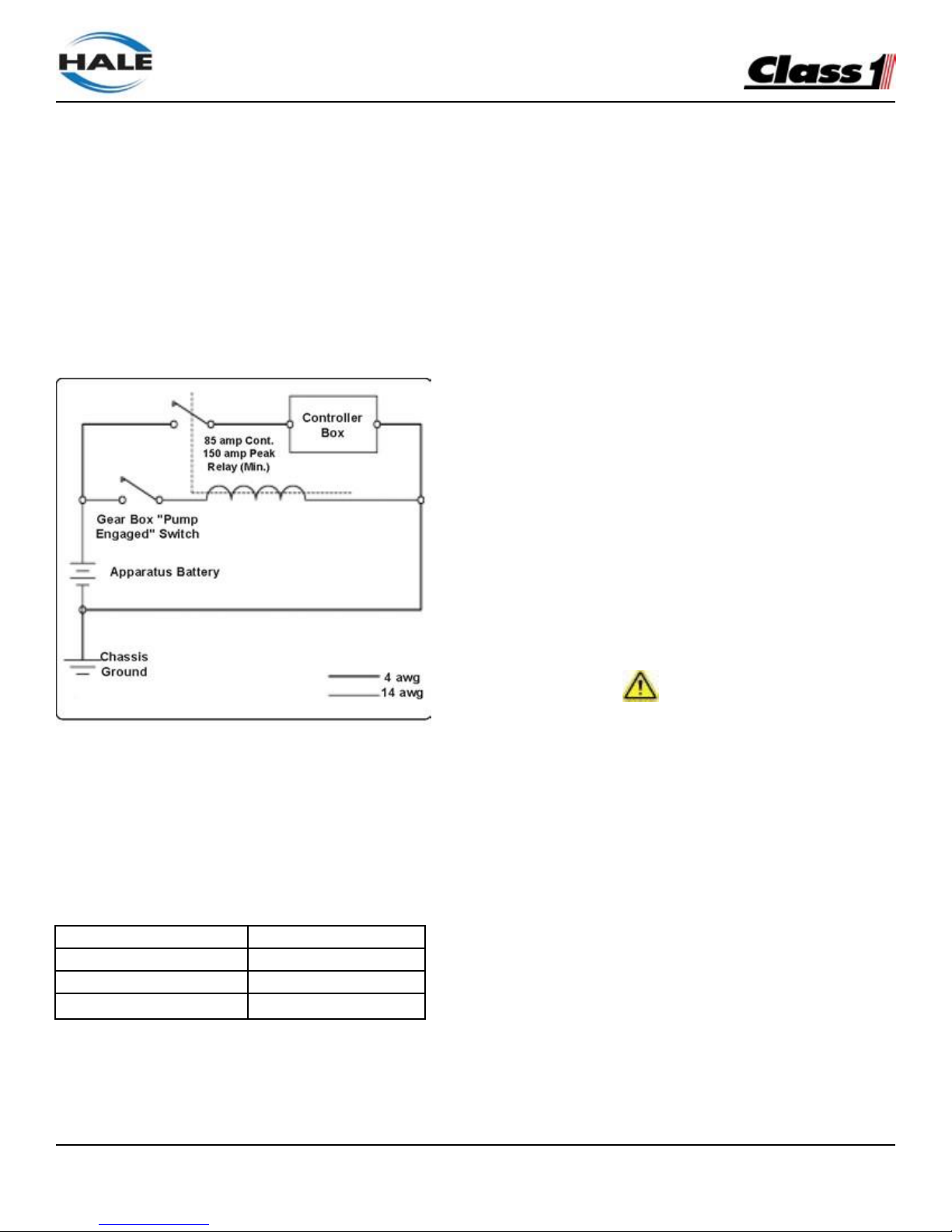
that power is supplied to the Hale Foam-Logix when
the main apparatus electrical system is energized
and the pump is in gear. Use of a solenoid with
a 150 AMP peak, 85 AMP continuous rating is
recommended. Figure 5: “Recommended Relay
Wiring Schematic” shows the recommended wiring
for this relay.
Note: This ensures immediate operation when
the operator places the apparatus in PUMP mode,
and to prevent battery power drain when the
apparatus is not running.
With Hale FoamLogix 2.1A and 1.7AHP cable
lengths up to 6’ (1.8 meters) require a minimum 8
AWG type SGX (SAE J1127) battery cable. (See
Table 6: “Recommended Primary Power Cable
Sizes.”) Use solder lugs on cable ends with a 5/16”
(8mm) diameter hole.
Models 3.3 and 5.0
Maximum length
8 AWG (8.4mm2)
6’ (1.8M) or less
4 AWG (21.2mm2)
6; (1.8M) to 15” (4.6M)
0 AWG (53.5mm2)
15’ (4.6M) or Longer
Table 6: Recommended Primary Power Cable Sizes
When planning cable runs make sure the primary
wires are routed by the shortest most direct route.
A braided flat ground strap connected to the
apparatus chassis is recommended for the ground
connection.
This limits the RFI/EMI interference encountered
with radios, computers or other sensitive electronic
equipment. The ground strap should be a minimum
of 1-1/4” (32mm) wide and no longer than 18”
(457mm). It must have soldered flat lug ends with
3/8” (10mm) diameter holes. If the ground strap
length exceeds 18” (457mm), a wider ground strap
should be used or use a double thickness of 1-1/4”
(32mm) wide ground strap. The ground strap must
be connected to the chassis. Use minimum 5/16” (8
mm) diameter bolt or mounting to secure the strap.
Power and ground must also be provided for the
display unit using the 2 pin Packard connector. The
power must be a minimum 5 amp dedicated and
fused circuit. The ground must be connected to the
chassis ground stud and protected from corrosion.
Make sure the ground is attached directly to the
chassis frame and not to the apparatus body work.
IMPORTANT!
BEFORE MAKING GROUND CONNECTIONS REMOVE
ALL PAINT, GREASE AND COATINGS FROM THE
CONNECTION AREA. AFTER MAKING CONNECTION,
SEAL AGAINST CORROSION. WHEN A FLAT GROUND
STRAP IS NOT AVAILABLE USE A BATTERY CABLE
ONE SIZE LARGER THAN THE POWER CABLE USED.
FOAM CONCENTRATE TANK
A foam concentrate tank must be supplied to suit
the capacity required for the apparatus application.
The tank must meet NFPA minimum standards for
its design capacity, including:
❑ Filler size
❑ Vapor pressure venting
❑ Baffling
❑ Drain facilities.
Figure 5: Recommended Relay Wiring Schematic
Page 34
FoamLogix, Model 2.1A and 1.7AHP Class “A”
Electronic Foam Proportioning Systems
34
Foam Pump Mounting
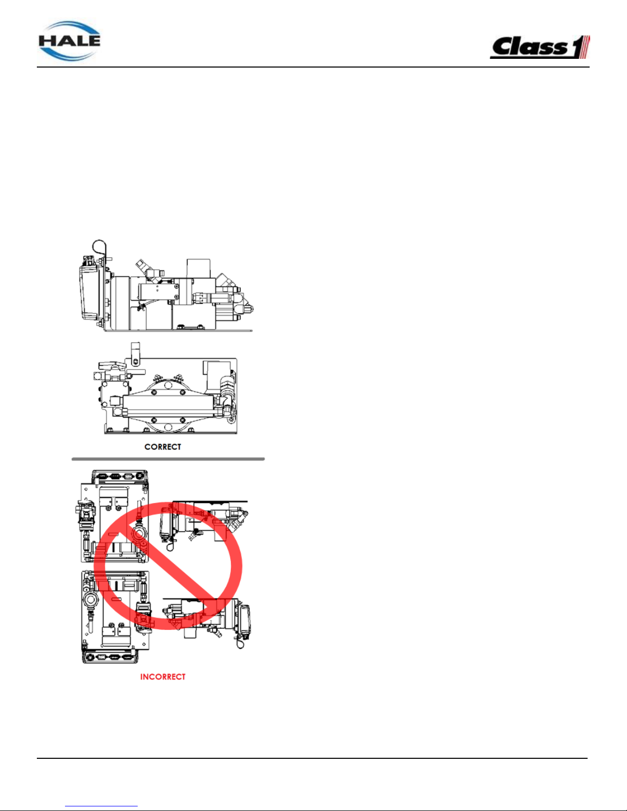
Position the foam pump and motor assembly in the
desired location on the apparatus. When installing
the foam pump and motor assembly, the assembly
should be kept in a HORIZONTAL position with the
base plate on the bottom (See Figure 7: “FoamLogix
Pump Installation.”)
Figure 7: FoamLogix Pump Installation
Although the system is sealed and designed to be
resistant to the harsh environment of fire fighting
apparatus, a compartment with easy operator
access is recommended.
The base plate of the foam pump and motor
assembly must be anchored to a surface or structure
that is rigid and of adequate strength to withstand
the vibration and stresses of apparatus operation.
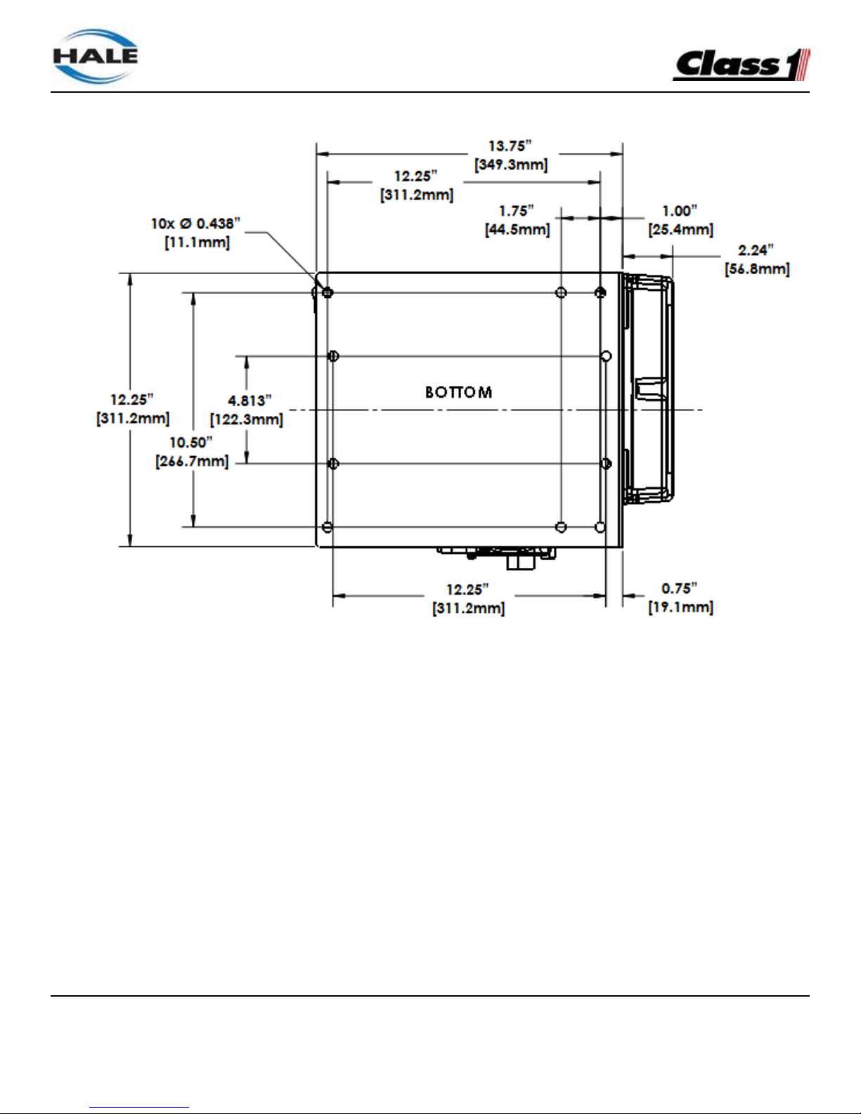
Figure 8: “Base Plate Mounting Hole Locations,” on
page 35, provides the mounting base dimensions
for the FoamLogix foam pump and motor assembly.
Make sure the foam concentrate hoses are properly
routed to the inlet and outlet on the foam pump.
Foam concentrate must gravity feed to the foam
pump inlet from the foam tank(s). The foam pump
must be mounted in an area to avoid excessive
engine exhaust system heat or accessory heat
buildup.
The base of the foam pump and motor assembly
includes 5/16” (8mm) diameter predrilled mounting
holes. The apparatus mounting location must to be
drilled accordingly. The base plate may be used as
a template to mark mounting hole location. Also see
Figure 8: “Base Plate Mounting Hole Locations” on
page 35.
PLUMBING INSTALLATION
Hale FoamLogix System plumbing diagram is
located on page 21 of this manual.
Page 35
FoamLogix, Model 2.1A and 1.7AHP Class “A”
Electronic Foam Proportioning Systems
35
Figure 8: Base Plate Mounting Hole Locations
The diagram provides recommended guidelines for
the installation of system components that handle
water, foam concentrate and foam solution. The
sequence in which the plumbing installation is
completed depends on your individual installation.
Water and Foam Solution Plumbing
When installing water and foam solution piping runs,
use best industry practices to install this piping. Use
a suitable pipe sealing compound at all joints.
Check Valve Manifold
Hale pre-made stainless steel foam manifolds
are recommended.
The manifolds are available in kits and eliminate
the extra labor and leaks from large pipe thread
connections.
The manifolds use 3” (76mm) Victaulic
connections and are available in single or dual
check valve configurations.
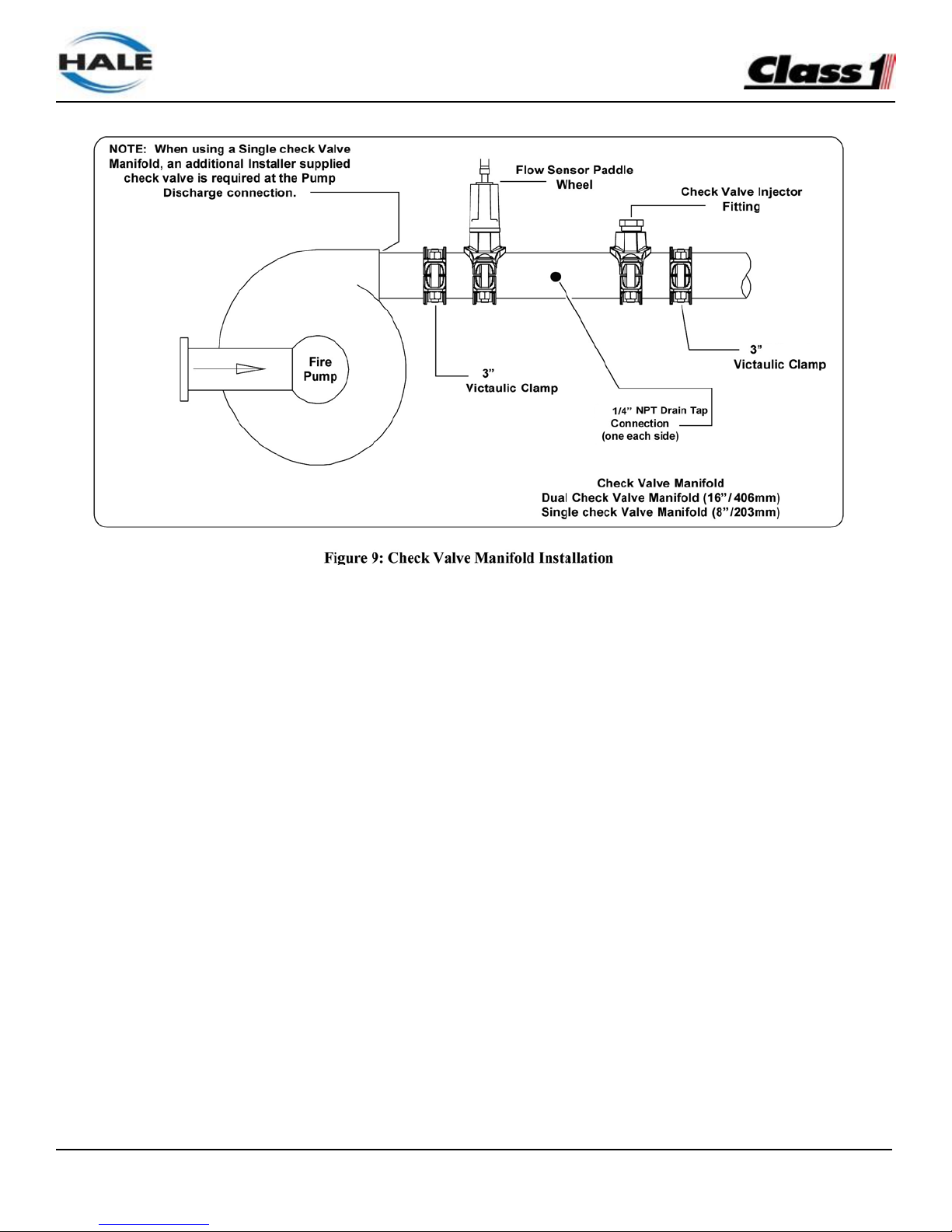
Figure 9: “Check Valve Manifold Installation,” on
page 36, shows a typical check valve manifold
installation.
Page 36
FoamLogix, Model 2.1A and 1.7AHP Class “A”
Electronic Foam Proportioning Systems
36
Note: When the manifold is installed the drain tap
that must be placed in the “down” position and
plumbed to an individual drain.
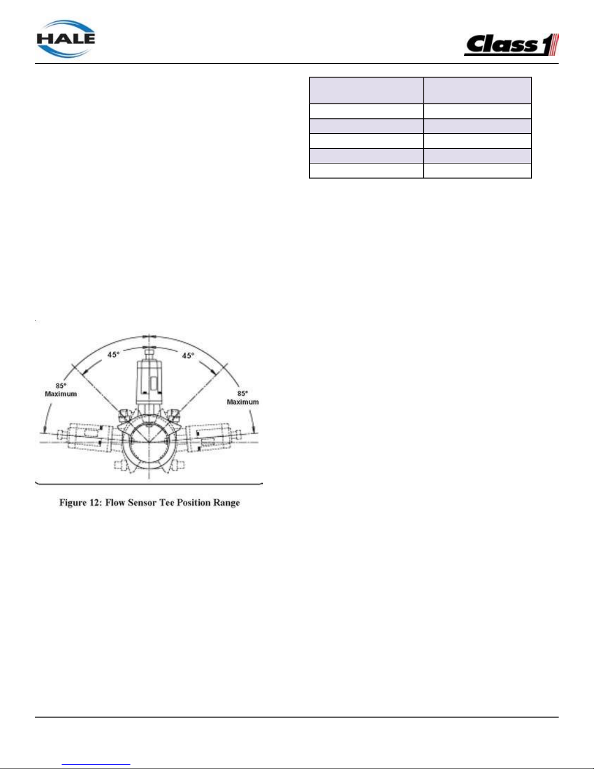
When properly mounted, the flow sensor and check
valve/injector fitting are on the side of the manifold
and one of the drain ports is on the bottom. The
flow sensor should point upwards slightly to allow
drainage of water and sediment. See Figure 12:
“Flow Sensor Tee Position Range,” on page 38.
Optional Hale Piping Components
Hale piping components, such as 3” (76mm) and 4”
(102mm) wafer-type check valves, 115 and 2433
series flanges, mini manifold, etc. are available
to simplify installation of water and foam solution
discharge piping.
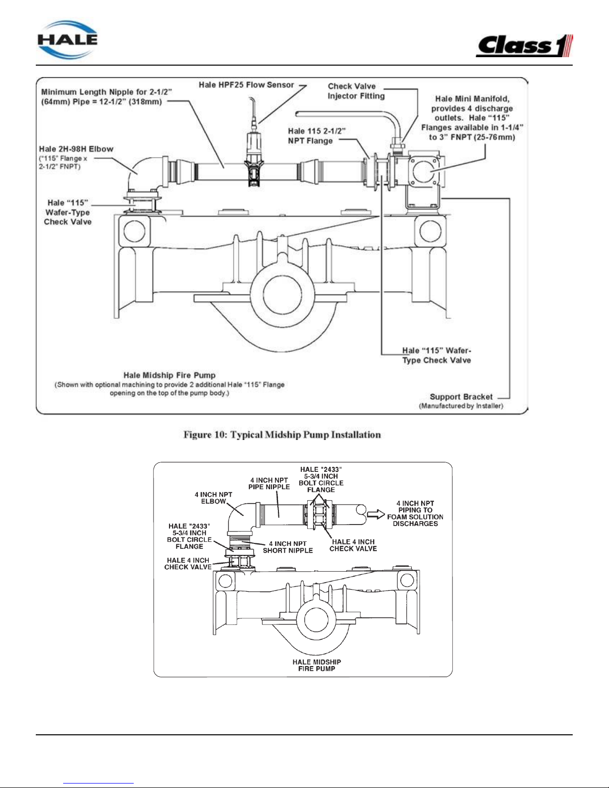
The arrangement shown in Figure 10: “Typical
Midship Pump Installation,” on page 37, provides
accurate proportioning across a wide range for up to
four discharges from the mini manifold.
The Hale mini manifold provides a 1” NPT tap for
installation of the check valve/injector fitting.
The Hale mini manifold and elbow components
offer 4-3/8” diameter bolt circles and minimize
fabrication and pipe work. After installation, make
sure all pipes, hoses and tubes are supported
using the best industry practices.
Figure 11: “Typical 4” Check Valve Installation,
Midship Pump” on page 37 shows a suggested
installation arrangement using Hale 4” (102mm)
check valves, pipe and Hale 2433 flanges.
“Waterway” Check Valves
Check valves in the waterway, rated at 500 PSI
(34.5 BAR), are required to keep foam solution out
of the main pump and allow pump priming without
drawing foam into the piping.
Page 37
FoamLogix, Model 2.1A and 1.7AHP Class “A”
Electronic Foam Proportioning Systems
37
Figure 11: “Typical 4” Check Valve Installation, Midship Pump
Page 38
FoamLogix, Model 2.1A and 1.7AHP Class “A”
Electronic Foam Proportioning Systems
38
Using double check valves, separated by at least
6” to 8” (152 to 203mm) of pipe before the foam
injection point, ensures that the pump and tank
water remain uncontaminated.
Flow Sensor
The Hale FoamLogix flow sensor is specially
designed to enable quick and easy sensor
inspection and maintenance. The flow sensor paddle
wheel is installed on a saddle clamp or weld fitting to
the foam-capable discharge piping of the apparatus.
In horizontal piping runs, the flow sensor is mounted
within the range shown in Figure 12: “Flow Sensor
Tee Position Range.”
When selecting a flow sensor, it is important
to consider the minimum and maximum flow
requirements during operation. Refer to the Figure
4: “Pipe Size vs. Flow Rate,” on page 24, for the
proper pipe size for flow range desired.
The flow sensor is installed in the piping before the
foam concentrate injection point.
This is true in applications where the foam system
needs to supply a 3” (76mm) deck gun, as well as
a 1” (25.4mm) booster line.
Table 13: Pipe Size vz. Minimum Straight Run
Pipe size for flow sensor mounting must be
selected to provide accuracy at the lowest flow rate.
Mounting the flow sensor in a short section of pipe,
one pipe size smaller (e.g., 4” to 3”; 3” to 2-1/2”,
etc.), provides better accuracy at the lower flows.
Refer to the Table 13: “Pipe Size vs. Minimum
Straight Run” for pipe size. Selecting the next
smaller pipe permits reducing the straight pipe
run the required distance prior to the flow sensor
paddle wheel.
In the short length of reduced pipe pressure loss
is minimal and there is minimal pressure loss
through elbows and fittings. See Figure 14: “Typical
Reduced Size Sensor Piping Arrangement” on
page 39.
Excessive turbulence in the flow sensor may
produce unstable and inaccurate flow readings.
The length of straight pipe prior to the flow sensor
must be sufficient to reduce any turbulence in the
pipe.
The following guidelines help attain the best
readings, and maintain Hale FoamLogix system
accuracy.
1.
A minimum of 6 times the pipe diameter
of straight run pipe without any fittings is
necessary prior to the flow sensor paddle
wheel. (See Figure 15: “Flow Sensor
Placement” on page 39.)
Pipe Size
Minimun Recommend-
ed Straight Run Pipe
1-1/2”
9”
2”
12”
2-1/2”
15”
3”
18”
4”
24”
Page 39
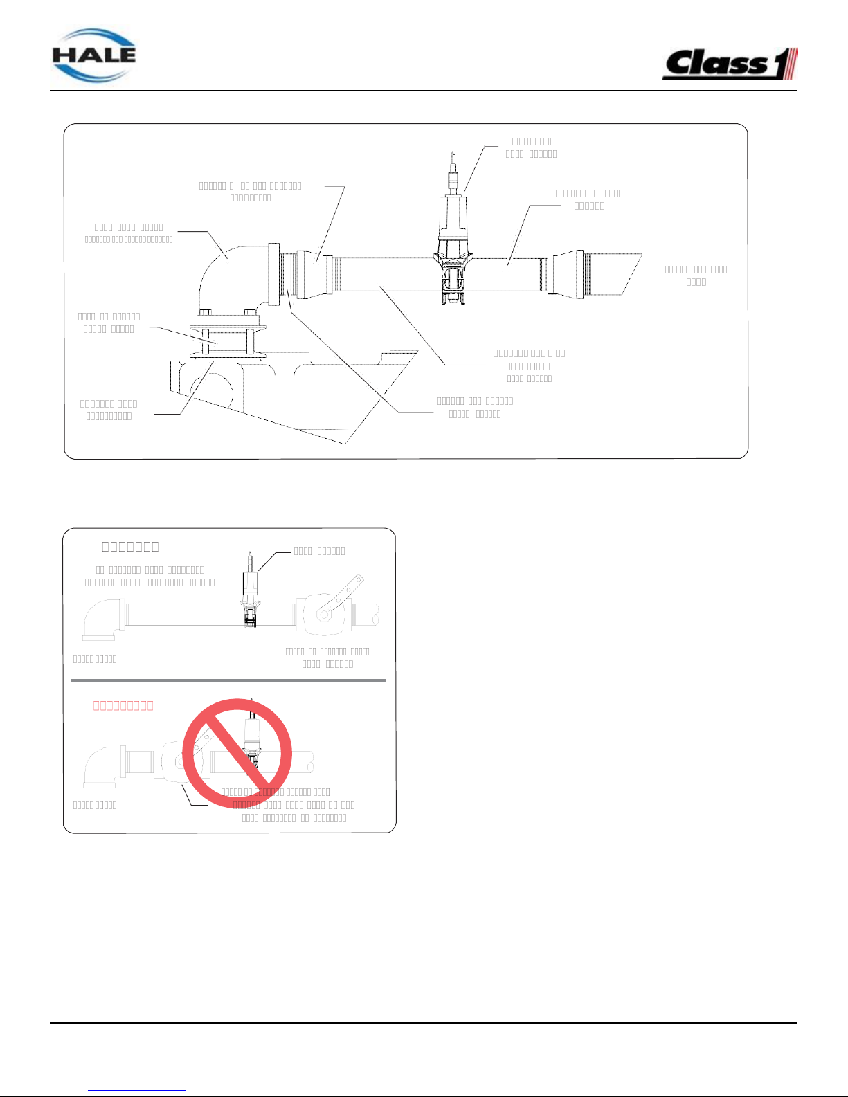
FoamLogix, Model 2.1A and 1.7AHP Class “A”
Electronic Foam Proportioning Systems
39
Figure 14: Typical Reduced Size Sensor Piping Arrangement
3. Do not mount a flow sensor directly after
an elbow or valve. Valves create severe
turbulence when they are “Gated”.
Saddle Clamp Installation
See Figure 16: Flow Sensor/Saddle Clamp
Installation“ on page 40.
Installation of the Paddle Wheel Flow Sensor
using a saddle clamp requires a 1.385“/ 1.390“
(35/35.3mm) bored hole in the pipe.
Figure 15: Flow Sensor Placement
2.
The downstream piping length is not as
critical, but there must be a short length
of straight pipe with no fittings or valves
immediately after the flow sensor paddle
wheel. Two to three times the pipe diameter
is recommended.
A minimum of six times the pipe diameter of straight
run pipe without any fittings is necessary prior to
the position of this hole.
The flow sensor requires a spacer and eight
stainless steel internal hex head screws. These
are supplied with the sensor.
Four 6-32 x 1/2“ screws attach the spacer to the
saddle clamp mount, and four 6-32 x 3/4“ screws
with lock washers attach the paddle wheel to the
spacer.
Page 40
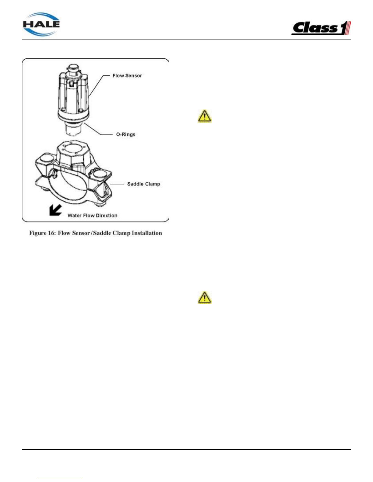
FoamLogix, Model 2.1A and 1.7AHP Class “A”
Electronic Foam Proportioning Systems
40
Align the indexing pin of the saddle clamp to the
indexing hole of the spacer to align the saddle
clamp mount.
Secure with four 1/2” machine screws, no lock
washers. Torque to 8.5 in.-lbs. (1.0 N-m).
Align the paddle wheel indexing pin to the indexing
hole in the spacer and secure using four 3/4”
screws and lock washers. Torque to 7.5 in.-lbs. (0.9
N-m).
Apply a small amount of grease to the saddle
clamp gasket before the final installation of the
assembly onto the pipe. Firmly tighten the saddle
clamp onto the pipe.
Foam Pump Flush System
The flushing water hose must be a minimum of
1/2” (12 mm) inside diameter. The flush water
supply
is provided from one of the pressure taps on the
discharge side of the fire pump.
It must be reduced to 50 PSI (3.5 BAR). It is
recommended to installed a check valve at the
pressure tap to prevent contamination.
FOAM CONCENTRATE PLUMBING
CAUTION!
MAKE SURE THE FOAM TANK AND FOAM CONCENTRATE SUCTION HOSES ARE CLEAN BEFORE
MAKING FINAL CONNECTION TO FOAM PUMP.
FLUSH TANK AND HOSES PRIOR TO MAKING
CONNECTIONS.
MAKE SURE THE FOAM CONCENTRATE IS
GRAVITY FED FROM THE TANK TO THE PUMP.
Foam concentrate plumbing consists of:
❑ Foam concentrate suction hose
❑ Foam strainer
❑ Foam concentrate discharge hose
❑ Check valve/injector fitting.
Foam Strainer Connection
CAUTION!
THE FOAM CONCENTRATE STRAINER ASSEM-
BLY, MOUNTED ON THE FOAM PUMP INLET, IS A
LOW PRESSURE DEVICE. IT WILL NOT WITHSTAND
FLUSHING WATER PRESSURE. IF FLUSHING
WATER IS TO BE PROVIDED THE PRESSURE MUST
BE LIMITED TO 50 PSI (3.5 BAR).
The strainer/valve assembly has 1/2” (12mm) NPT
female threaded ports. A 1/2” hose barb fitting is
supplied to connect the 1/2” ID hose, provided with
the Hale Foam-Logix 2.1A installation kit.
Page 41
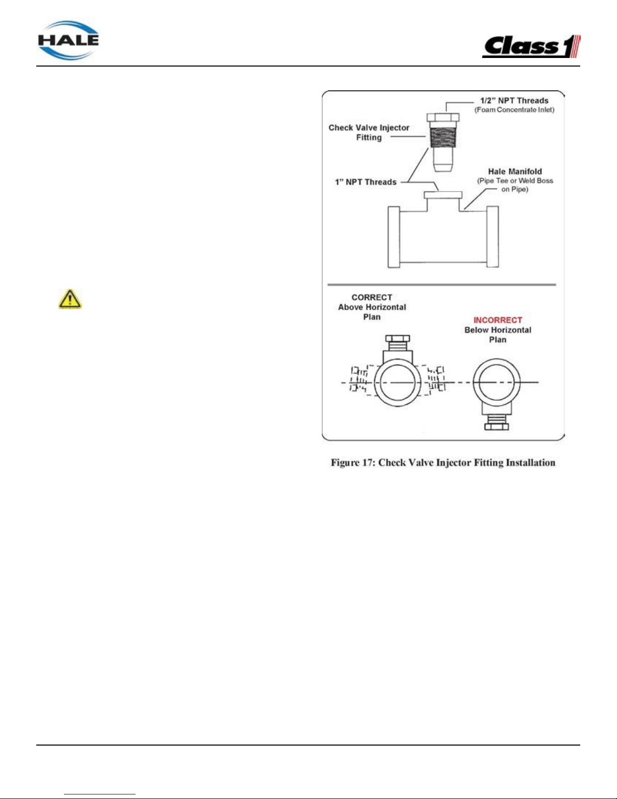
FoamLogix, Model 2.1A and 1.7AHP Class “A”
Electronic Foam Proportioning Systems
41
The hose from the foam tank to the strainer must
have adequate wall stiffness to withstand the
vacuum of the foam pump while it is operating (23”
[584 mm] Hg and 50 PSI [3 BAR], Kuriyama, Kuritec K-3130 or K-7130 series or equal).
After the foam pump is mounted on the apparatus,
connect the PVC hose provided to the strainer inlet.
Install the clear plastic hose from the foam tank
outlet to the inlet of the strainer/valve assembly.
The inlet is on the valve end. Wetting the ends
of the hose and fittings makes the installation on
the hose fittings easier.
CAUTION!
MAKE SURE THE FOAM TANK AND FOAM CONCENTRATE SUCTION HOSES ARE CLEAN BEFORE
MAKING FINAL CONNECTION TO FOAM PUMP. IF
NECESSARY FLUSH TANK AND HOSES PRIOR TO
MAKING CONNECTION.
Check Valve/Injector Fitting
The Hale check valve/injector fitting, supplied
with the Hale FoamLogix system, meets NFPA
requirements for a non-return device in the foam
injection system. It prevents back flow of water into
the foam concentrate tank.
When properly installed the brass and stain-
less steel construction check valve/injector fitting
ensures foam concentrate is injected into the
center of the water flow for better mixing.
Note: Always position the check valve/ injector fitting
at a horizontal or higher angle to allow water to drain
away from the fitting. (See Figure 17: “Check Valve
Injector Fitting Installation.”) This avoids sediment
deposits or the formation of an ice plug.
The check valve/injector fitting MUST be mounted
in a location that is common to all discharges which
require foam concentrate. (See Figure 18: “Injection
and bypass Hose Connection”)
The Hale FoamLogix system DOES NOT permit
a separate injection point for each foam capable
discharge.
The check valve/injector fitting has – 1” NPT
(25.4mm) threads on the outside, to fit into the 1”
NPT threaded connection on the Hale mini manifold
a pipe tee, or a 1” NPT weld fitting installed in the
discharge piping of the fire pump. (See Figure 17:
“Check Valve Injector Fitting Installation.”)
Page 42
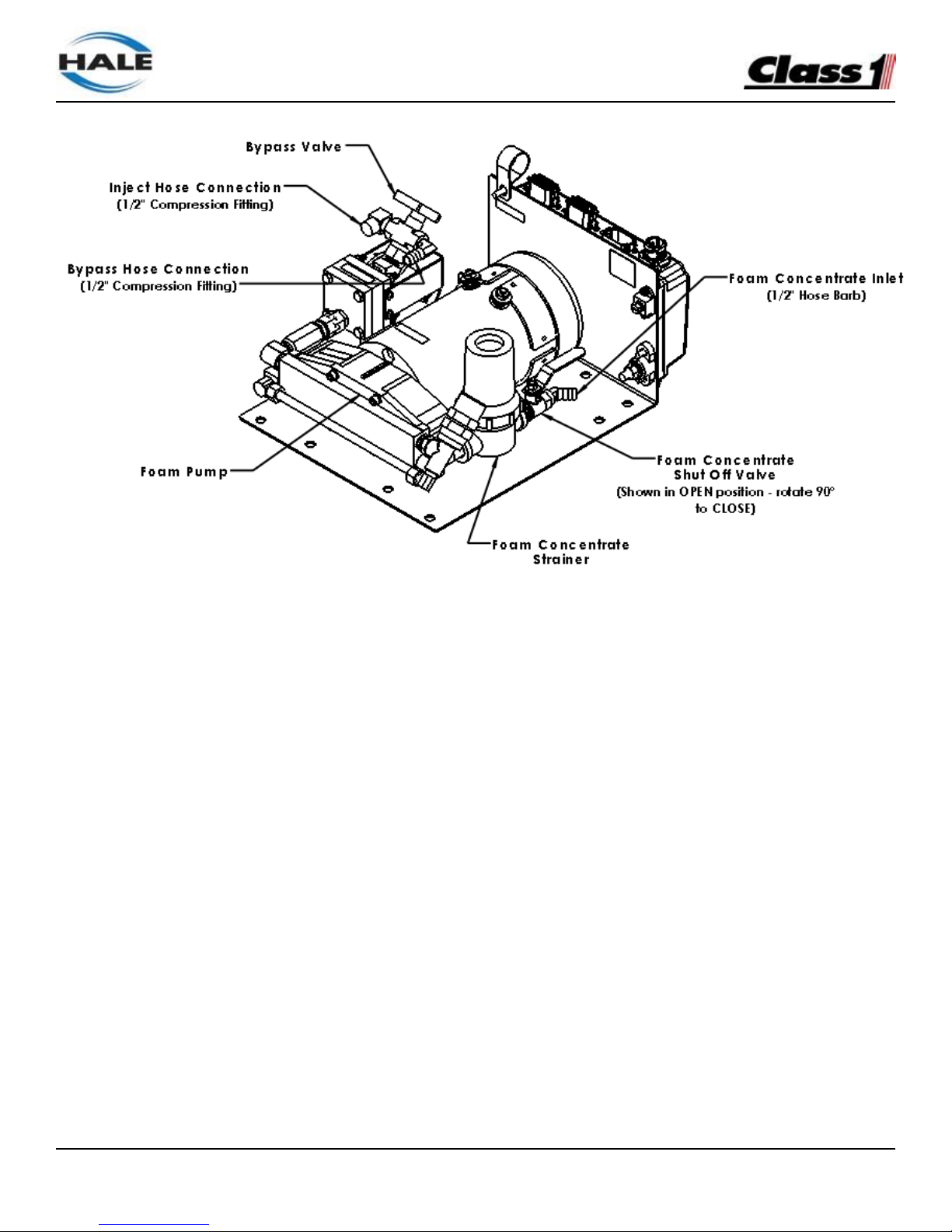
FoamLogix, Model 2.1A and 1.7AHP Class “A”
Electronic Foam Proportioning Systems
42
Figure 18: Injection and Bypass Hose Connection
The inlet connection of the check valve/ injector
fitting uses a 1/2” NPT female thread.
Foam Concentrate Injection Hose
Connect a hose from the foam pump inject port
to the inlet of the check valve injector fitting.
(See Figure 18: “Injection and Bypass Hose
Connection”)
The hose and fittings from the INJECT port to the
check valve injector fitting should have minimum
1/2” (13 mm) outside diameter and be rated at 500
PSI (34 BAR) working pressure (Aeroquip 2580-10
or equal).
Bypass Hose Connection
A bypass valve is mounted on the discharge of the
foam pump. The bypass handle must be accessible
by the pump operator during normal operations.
The bypass is a 3-way directional valve. Determine
which port is the INJECT port and which port is the
BYPASS. (See Figure 18: “Injection and Bypass
Hose Connection”)
Bypass hose connections are 1/2”. Hose fittings
compatible with all foam concentrates must be
provided. The hose from the BYPASS port is
plumbed to the atmosphere.
This hose is used for calibrating the foam pump,
pumping the concentrate into a container to empty
the foam tank or to assist in priming of the foam
pump. The hose from the BYPASS port must be
long enough to reach a container outside the truck.
Page 43

FoamLogix, Model 2.1A and 1.7AHP Class “A”
Electronic Foam Proportioning Systems
43
ELECTRICAL INSTALLATION
Electrical Connections
Complete harness electrical diagrams are provided
on page 45 of this manual. Refer to these diagrams
for proper installation of each of the electrical
components.
The Hale FoamLogix system is designed to be
installed with a minimum of electrical connections.
Cables are provided with each Hale FoamLogix
system to make the flow sensor, control unit and
motor controller box connections.
The system installer must supply primary power
wire, low tank level sensor wire and flat braided
ground straps.
CAUTION!
❑ Review the “Safety” section of this manual,
beginning on page 11, in its entirety before
proceeding with electrical connections.
❑ To prevent system damage or electrical shock the
main power supply wire must be the last
connection made to the Hale FoamLogix motor
controller box. See Figure 3: “Typical Hale
FoamLogix 2.1A and 1.7APH System Layout” on
page 21.
❑ The cables provided with each Hale FoamLogix
system contain shielded assemblies.
NEVER attempt to shorten or lengthen
the shielded cables. If necessary order
longer or shorter cables from Hale Products
to suit the particular installation.
❑ The cables are indexed so they connect to the
correct receptacle one way only. When making
cable connections DO NOT force mismatched
connections as damage can result, causing
improper system operation.
❑ The cables shipped with each Hale FoamLogix
system are tested at the factory with that unit.
Improper handling and forcing connections can
damage these cables which could result in other
system damage.
❑ The system can only perform when the electrical
connections are sound. Make sure each electrical
connection is correct.
❑ Hale FoamLogix systems are designed for use
on direct current, negative (–) ground apparatus
electrical systems only.
❑ Do not mount radio transmitter or transmitter
cables in direct or close contact with the Hale
FoamLogix unit.
❑ Before connecting the cables, inspect the O-ring
seal in the female connector. If the seal washer
is missing or damaged, water can enter the
connector causing corrosion of the pins and
terminals resulting in possible system failure.
❑ The ground strap must be a minimum of 1-1/4”
(32mm) wide and no longer than 18” (457mm).
A longer ground strap must be wider or a
double thickness strap must be used. Make
sure the ground strap is attached to the
chassis frame. Grounding to the body IS NOT
acceptable.
❑ Always disconnect the power cable, ground
straps, electrical wires and cables from the
control unit or other Hale FoamLogix equipment
before electric arc welding at any point on the
apparatus. Failure to do so could result in a
power surge through the unit that could cause
irreparable damage.
❑ There are no user serviceable parts inside
Hale FoamLogix system electrical/ electronic
components. Opening of these components
(motor controller box or control unit) voids the
warranty.
Page 44
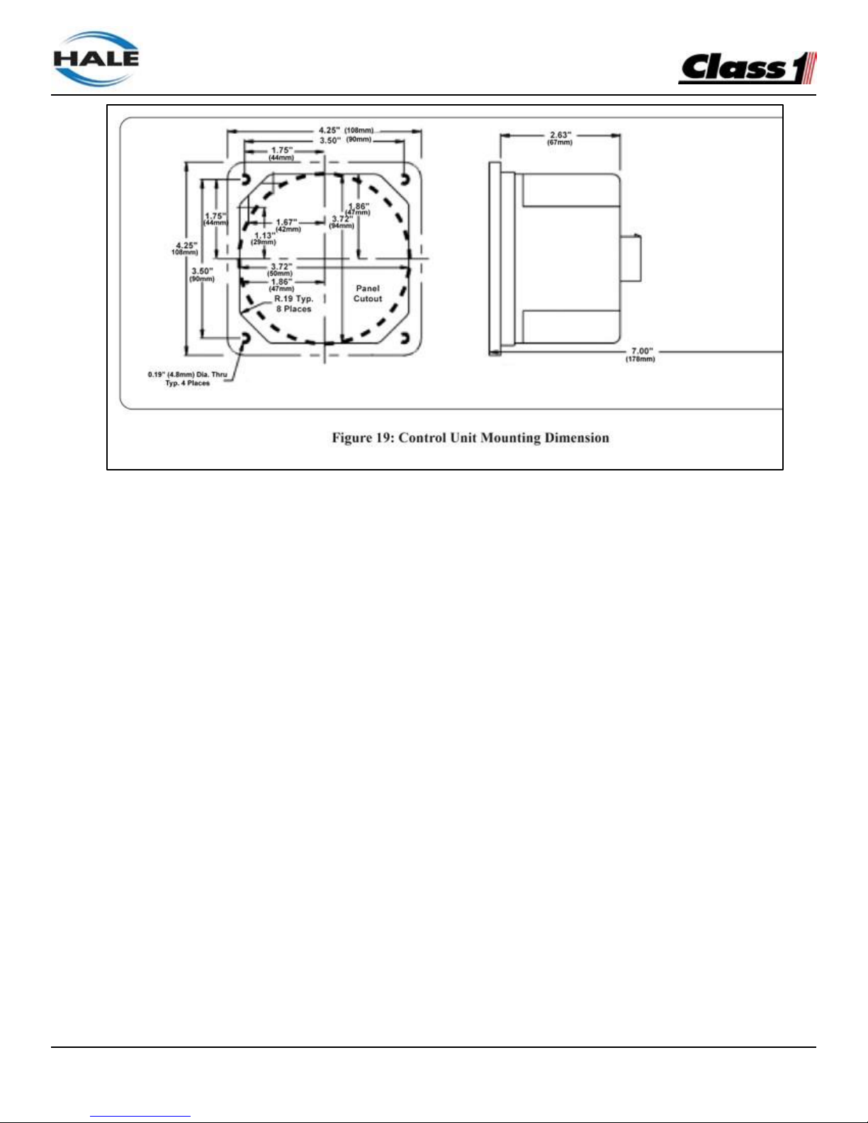
FoamLogix, Model 2.1A and 1.7AHP Class “A”
Electronic Foam Proportioning Systems
44
Control Unit
The control unit mounts in the operator panel of
the apparatus. The display is secured with four #8
socket head screws. (See Figure 19 “Control Unit
Mounting Dimension” for mounting dimensions).
The display requires a 7” (178mm) minimum
clearance from the back of the operator panel to
allow proper connection of cables. Once the control
unit is mounted on the operator panel, attach the
14 pin AMP connector on the cable assembly to the
back of the display. Referring to Figure 20: “Control
Harness Connections” and Figure 21: “System
Power and Ground Connections,” on page 45, make
connections to the motor controller box and flow
sensor.
Notes: Ensure that the panel where the control unit
is mounted has an adequate ground. For stainless
steel and vinyl coated panels a ground strap ½ inch
(12mm) wide must be attached from one of the four
screws holding the control unit in place to the frame
of the fire truck to ensure adequate grounding.
Allow a service loop to prevent “pulling” of the wires
or connectors during body and frame flex.
Display Unit Power and Ground
Connections
Power must be connected directly to the display
unit. The power and ground connection is the 2-pin
packard connector on the 12”(305mm) long pigtail of
the harness (see Figure 20 on page 45).
The mating harness provided is approximately 18”
(457mm) long. If additional wire length is required,
use minimum 16 AWG type SXL, or GXL (SAE
J1128) wire.
Connect the black (B) wire to a chassis ground
stud. Protect the ground connection from
corrosion.
Connect the red (A) wire to the power supply. It
is recommended to connect the power wire to
a minimum 5 AMP, fused, dedicated circuit. If a
dedicated circuit is not available, the power lead
may be connected to a terminal where there is
not a HIGH current load. Acceptable additional
components powered from this terminal include
ENFO IV, Governor, Tank Level Gauge, Etc.
Page 45
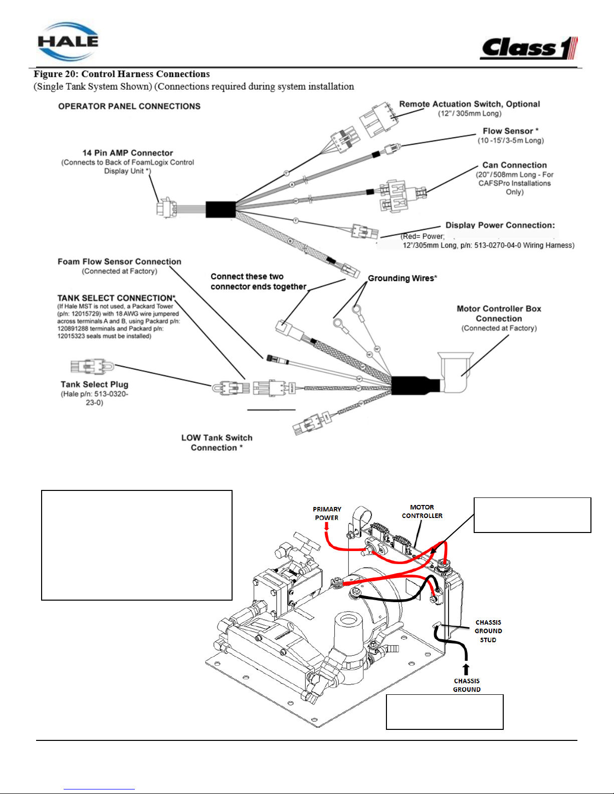
FoamLogix, Model 2.1A and 1.7AHP Class “A”
Electronic Foam Proportioning Systems
45
PRIMARY POWER CONNECTION
(40 AMPS Minimum - 8 AWG TYPE SGX
(SAE J1127) Minimum for lengths up to
6’. For lengths over 6’ see Table 6 on
page 31. Use silicone sealane to
prevent corrosion and use rubber boot
provided to prevent short circuit.)
Wire Harness
Connection (113434)
Figure 21 Power
Connection
Page 46

FoamLogix, Model 2.1A and 1.7AHP Class “A”
Electronic Foam Proportioning Systems
46
Motor Ground / Primary Power
CAUTION!
CONNECT THE PRIMARY POSITIVE LEAD FROM
THE TERMINAL BLOCK TO THE MASTER SWITCH
TERMINAL OR RELAY TERMINAL USING MINIMUM 8
AWG TYPE SGX (SAE J1127), CHEMICAL RESISTANT,
BATTERY CABLE AND PROTECT WITH WIRE LOOM.
PREVENT CORROSION OF POWER AND
GROUND CONNECTIONS BY SEALING THESE
CONNECTIONS WITH THE SILICONE SEALANT
PROVIDED.
Ground Connection
Be sure the Hale FoamLogix system is grounded to
the chassis. Use a short length of wide flat ground
strap at least 1-1/4” (32 mm) wide and less than 18”
(457 mm) long to reduce the potential of RFI emitted
by this connection.
A stud is located on the mounting base to attach
the chassis ground strap to the Hale FoamLogix
system. (See Figure 21: “System Power and Ground
Connections” on page 45.)
When making the ground strap connections
make sure lugs are soldered to the strap ends
for trouble free connections. Seal all connection
against corrosion.
When the length of the ground strap exceeds 18”
(457 mm) use a wider strap or a double thick strap.
CAUTION!
DO NOT CONNECT THE MAIN POWER LEAD TO
SMALL LEADS THAT ARE SUPPLYING SOME OTHER
DEVICE, SUCH AS A LIGHT BAR OR SIREN. THE
HALE FOAMLOGIX MODELS 2.1A AND 1.7AHP
REQUIRE 40 AMP MINIMUM CURRENT.
Primary Power Supply Connection
Make sure adequate switched electrical power from
the battery + terminal to the battery connection stud
on the motor controller box is provided. (See Table
6: “Recommended Primary Power Cable Sizes” on
page 33.)
Use 8 AWG minimum type SGX (SAE J1127)
battery cable directly to the battery, battery switch or
solenoids for cable runs up to 6’
(1.8 meters) long. Longer wire runs may require
larger battery cable for proper operation. DO NOT
connect power to the same connection as the
pump primer.
RFI/EMI
Electrically shielded cables for control unit and
flow sensor are provided with the Hale FoamLogix
system. The cables are 100% electrically shielded
to eliminate the potential problem of EMI/RFI.
Proper installation of system components and
cables along with proper grounding will limit radio
interference caused by the Hale Foam-Logix
system. Additionally, make sure radio cables and
hardware are not located in the immediate area
where Hale FoamLogix equipment is mounted.
Making round coils of extra control and flow sensor
cables in the pump compartment can act as an
antenna. While the control and flow sensor cables
cannot be shortened, various lengths of cable are
available to minimize the “extra” cable in the truck.
When routing control and flow sensor cables take
care to avoid routing them next to antenna wires,
radio power lines and radio components. When
there is extra cable, double the cable back on itself
and secure with plastic wire ties in a flat bundle
instead of making a round coil. (See Figure 22:
“Extra Cable Storage” on page 47.)
Page 47
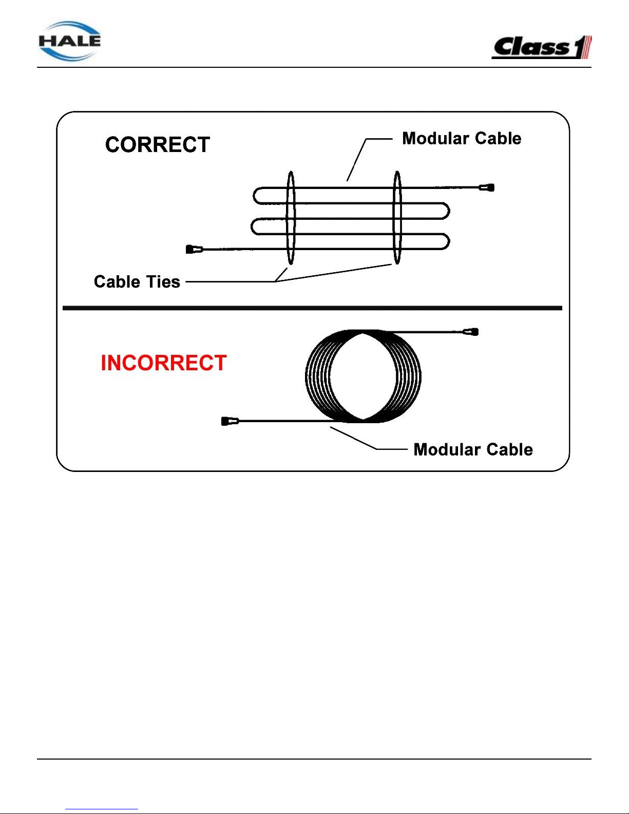
FoamLogix, Model 2.1A and 1.7AHP Class “A”
Electronic Foam Proportioning Systems
47
Figure 22: Extra Cable Storage
Page 48

FoamLogix, Model 2.1A and 1.7AHP Class “A”
Electronic Foam Proportioning Systems
48
START-UP CHECKLIST
Before energizing the apparatus and Hale FoamLogix system for the first time make sure the
following items are checked:
ELECTRICAL
❑ Tank level sensor wires connected to distribution
box and sealed from moisture.
❑ Tank level sensor functions properly.
❑ Control cable connection at distribution box
correct and tight.
❑ Flow sensor cable properly connected.
❑ All cables and wires are secured and protected
from damage during operation.
❑ Control and flow sensor cables properly folded
and secured; radio antennas, power lines and
equipment away from cables.
❑ Foam pump and motor assembly properly
grounded using flat ground strap.
❑ Correct voltage provided. Direct current,
negative (–) ground.
❑ Adequate current, 40 AMPS minimum, available.
Main power direct to battery, battery switch or
solenoid without primer or other accessories
tied in.
❑ Primary electrical and ground connections tight
and protected from corrosion with silicone
sealant.
❑ Splices in wires sealed from moisture using
adhesive filled heat shrink tubing.
LIQUID
❑ Flow sensor mounted with flow arrow in the
correct direction for water flow.
❑ Check valves are properly mounted in water and
foam concentrate lines.
❑ Strainer mounted for proper concentrate flow
direction in foam tank to pump hose.
❑ Foam tank to foam pump valve is in place and
open.
❑ Check valve/injector fitting lines are proper size
and connections are tight.
❑ Bypass valve is properly mounted and oriented
for direction of concentrate flow.
❑ Foam concentrate gravity feeds to foam pump
from foam concentrate tank.
❑ All hoses free of kinks and sharp bends.
❑ No sharp bends that can trap air exist in system.
❑ Flush water connections correct and tight.
❑ Discharge piping hydro tested in accordance
with NFPA/UL requirements.
❑ Bypass valve handle is in the INJECT position.
FOAM PUMP
❑ Foam pump and motor assembly mounted in
horizontal position with base plate down.
❑ Foam pump and motor assembly properly
secured using proper mounting hardware.
❑ Foam pump suction and discharge hoses
connected to proper ports.
❑ Foam pump suction and discharge hose fittings
tight.
Page 49
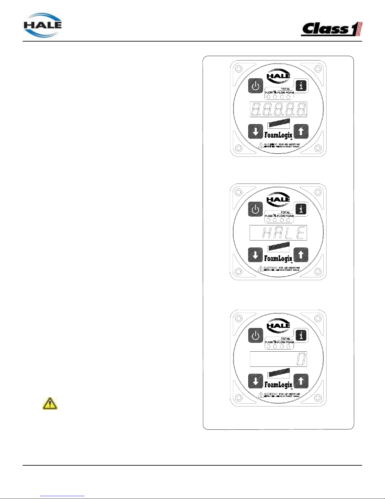
FoamLogix, Model 2.1A and 1.7AHP Class “A”
Electronic Foam Proportioning Systems
49
System Installer Start-up
On initial power-up of the Hale FoamLogix system,
at the installer facility, the following procedures must
be followed.
INITIAL SYSTEM POWER CHECK
Watch the display on the control unit as the
apparatus electrical system is turned ON. Check
the control unit readout for:
❑ FLOW
❑ TOTAL FLOW
❑ % FOAM
❑ TOTAL FOAM
❑ all bar graph LEDs light
❑ “88888” appears for several seconds
❑ “HALE CLASS 1 2002” (or “HALE CLASS
1 [CURRENT DATE]”) scrolls across the
display
❑ The default display, zero (0), if no water is
flowing and FLOW LED
(See Figure 23: “Control Unit Ready Indication”)
If a default display does not appear, refer to Section
6: TROUBLESHOOTING for possible WARM-UP/
SYSTEM CHECKING causes and solutions.
INITIAL SYSTEM CHECK
After initial system power-up, low tank level sensor
operation, foam pump operation and flow sensor
calibration must be checked per the following:
CAUTION !
WATER IS USED AT THE SYSTEM INSTALLER
FACILITY TO VERIFY LOW TANK LEVEL SENSOR
SYSTEM READY OPERATION AND FOAM PUMP
PERATION AS THE END USER SPECIFIED FOAM
CONCENTRATES MAY NOT BE READILY AVAILABLE.
Figure 23: Control Unit Ready Indication
INITIAL POWER-UP
WARM- UP/ SYSTEM CHECKING
SYSTEM READY
Page 50
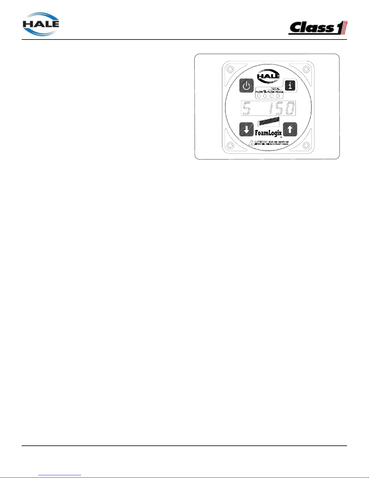
FoamLogix, Model 2.1A and 1.7AHP Class “A”
Electronic Foam Proportioning Systems
50
DO NOT PUMP WATER WITH THE HALE FOAMLOGIX FOAM PUMP FOR MORE THAN ONE (1)
MINUTE. DO NOT ATTEMPT TO CALIBRATE FOAM
PUMP FEEDBACK SENSOR WITH OTHER THAN
END USER SPECIFIED FOAM CONCENTRATE.
MAKE SURE THE BYPASS VALVE IS IN THE
BYPASS POSITION WHEN PUMPING WATER
WITH THE FOAM PUMP.
1.
Upon initial power-up with the foam tanks empty,
the display on the control unit alternates between 0
and Lo A, indicating the foam tank is empty.
Fill the foam concentrate tank with WATER. The Lo
A indication clears from the display, indicating the
low tank level sensor is operating properly.
2.
Place the bypass valve to the BYPASS position
to check foam pump operation. Place a calibrated
five gallon container at the discharge of the bypass
hose.
3. Place the system in simulated flow mode by
pressing the SELECT DISPLAY button
(i ) until the LED under FLOW lights. Then
press both up and down buttons
simultaneously.
Set simulated flow value to 100 GPM by
pressing UP or DOWN button. The
display shows S at the left most position to
indicate the simulated flow. (See Figure
24: “Simulated Flow Display.”)
4.
Press the (i ) button until the LED under %
FOAM lights. Set foam concentrate injection rate to
1.0 using the UP or DOWN button.
5.
Cycle the (i) button until the LED under TOTAL
FOAM lights. Press the ON button to energize the
Hale FoamLogix system.
Figure 24: Simulated Flow Display
Observe the discharge at the bypass hose to make
sure the foam pump is operating.
6.
After one minute press the ON button again to
STOP the foam pump. Approximately one gallon (3.8
liters) of water should discharge into the container.
The TOTAL FOAM display reads approximately 1.0.
7.
Exit the simulated flow mode by selecting the
FLOW display and pressing both up and down
buttons simultaneously.
8.
Drain water from foam tanks and concentrate
lines and return the bypass valve to the INJECT
position.
9. Verify operation of the flow sensor. Also calibrate
the flow sensor using the calibration procedures.
See heading “User calibration” beginning on page
53.
This completes the Hale FoamLogix system
operation checks accomplished at the system
installer facility.
Foam pump feedback calibration along with
setting of user specified default simulated flow and
concentrate injection rates should be accomplished
upon delivery to the end user using actual end user
specified foam concentrates and default values.
Page 51

FoamLogix, Model 2.1A and 1.7AHP Class “A”
Electronic Foam Proportioning Systems
51
INSTALLATION AND DELIVERY CHECK LIST
After the Hale FoamLogix system is installed, use the following check list to verify installation and ensure proper
system setup when the apparatus is delivered to the end user.
INSTALLATION
DATE INITIALS
❑ System properly installed. (Review “Start-Up Check List” on page 48.)
❑ Tank level sensor function verified. (Review “System Installer Start-Up” on page 49.)
❑ Foam pump operation checked. (Review “System Installer Start-Up” on page 49.)
❑ Foam tank and hoses drained of water. (Review “System Installer Start-Up” on page 49.)
❑ Flow sensor function checked and calibrated. (Review “User Calibration” on page 53.)
DELIVERY
DATE INITIALS
❑ Foam tank filled with user specified foam concentrate. (Compies with Hale approved
concentrate compabibility list.)
❑ Foam pump priming checked.
❑ Flow sensor calibration verified with Pitot.
❑ Default simulated flow value set to end user specification.
❑ Default foam concentrate injection rate set to end user specification.
❑ Foam concentrate feedback value verified and calibrated with end user specified foam.
❑ Proper Hale FoamLogix system operation demonstrated to end user in accordance
with manual procedures.
DATE INITIALS
❑ End user trained in proper operation of Hale FoamLogix system in accordance
with manual procedures.
❑ Warranty registration card filled out by end user and mailed to Hale Products.
❑ Two copies of Description, Installation and Operation manual provided to end user.
Page 52

FoamLogix, Model 2.1A and 1.7AHP Class “A”
Electronic Foam Proportioning Systems
52
NOTES
Page 53
FoamLogix, Model 2.1A and 1.7AHP Class “A”
Electronic Foam Proportioning Systems
53
USER CALIBRATION
The complete Hale FoamLogix Systems; foam pump
and motor assembly, control unit and flow sensor, is
tested at the factory before shipping to the installer.
If the Hale FoamLogix system is properly installed,
further calibration IS NOT necessary until delivery to
customer.
The system permits easy checking of component
calibration to assure accurate operation. The
calibration process verifies component calibration
and allows adjustments to the flow sensor and
feedback sensor display readings, to allow for
variations in apparatus piping configurations and
end user selected foam concentrate.
Default values for simulated flow and foam
concentrate injection rate may be set to end user
specifications while in the calibration mode.
Note: The Hale FoamLogix system is calibrated
at the factory to U.S. measurement (GPM, PSI,
GALLONS, etc.) units. The system may be set
to Metric units. (See heading “English to Metric
Units” on page 58.) However, the same unit
of measurement must be used throughout the
calibration process to ensure proper proportioning
by the system.
Recalibration of the system may be required ONLY
after major repairs or component changes are made
to the Hale FoamLogix foam system. Different
viscosity foam concentrates may also required
recalibration.
ENTERING PASSWORDS
Entering passwords is accomplished using the
control unit function buttons.
To enter passwords, press and hold the DISPLAY
button. The display shows PASS, then clears. While
continuing to hold the display button press the or
buttons sequentially to enter the password. See
Table 25: “Password Sequence.”
Table 25: Password Sequence
RESTORE FACTORY DEFAULTS
To return to the factory default values, enter the
restore factory values password (
) as
previously described.
Once the password is entered correctly the unit
displays FAC and returns to normal operation.
Factory default values:
Simulated Flow.... 150 GPM (568 LPM) %
FOAM .............. 0.5% Class “A”
Also see Figure 26: “Display - Password and
Calibration Modes” on page 54.
CALIBRATION
1 To enter calibration password press and hold
the SELECT DISPLAY button (i). The display
shows PASS, then clears.
2 While holding i pressed, enter the calibration
password ().
3 The display shows CALL for several seconds,
followed by L (or O when display is set to
metric). (See Figure 26: “Display - Password
and Calibration Modes” on page 54.)
The FLOW LED (Water Flow sensor
Calibration) also illuminates. (See Figure
27: “Display - Flow Sensor Calibration” on
page 54.)
Mode
Password Sequence
User Calibration
Restore Factory Defaults
Page 54
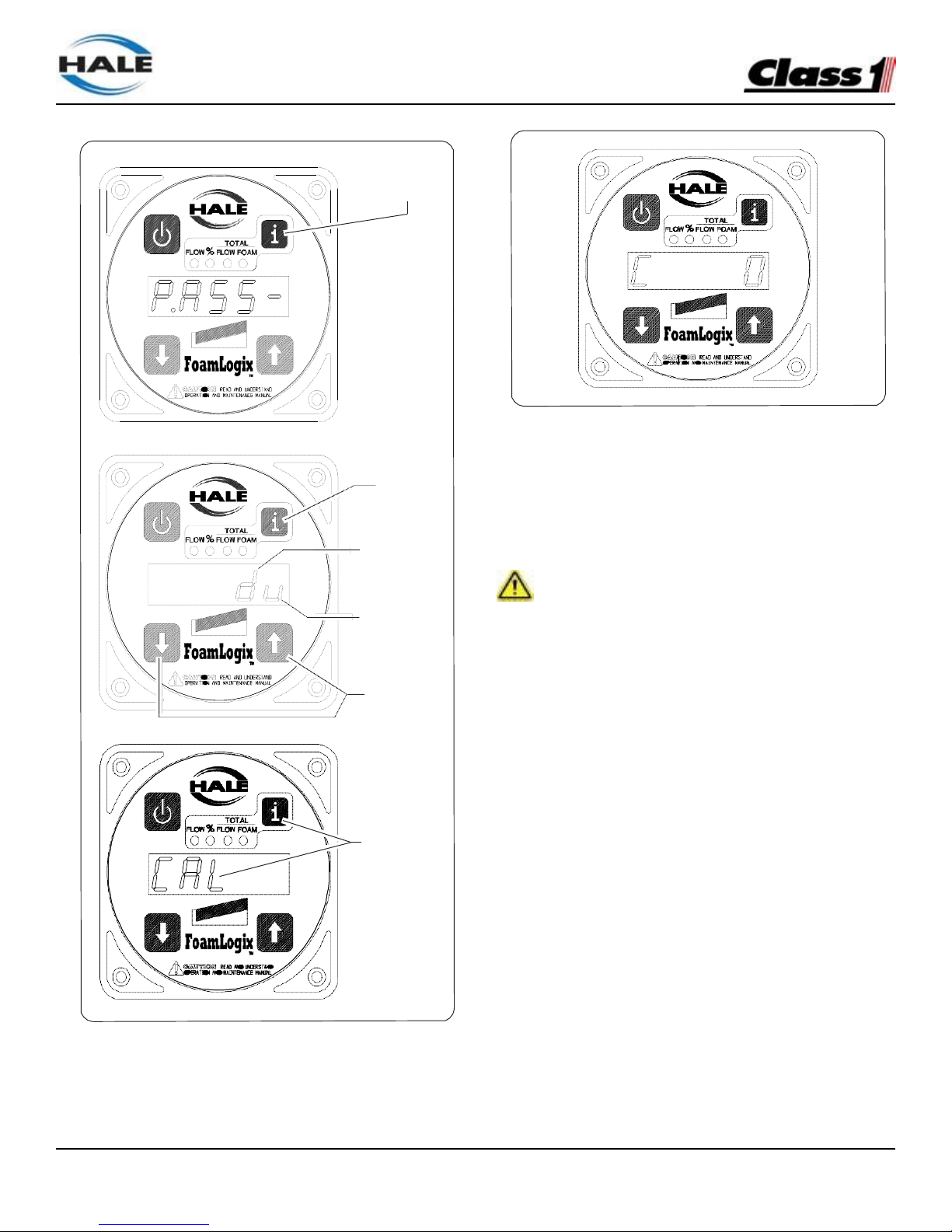
FoamLogix, Model 2.1A and 1.7AHP Class “A”
Electronic Foam Proportioning Systems
54
27: Display - Flow Sensor Calibration
FLOW SENSOR CALIBRATION
Verify flow sensor calibration during NFPA/UL testing
of the apparatus and delivery to end user.
IMPORTANT!
AN ACCURATE FLOW MEASURING DEVICE MUST
BE USED TO MEASURE THE WATER FLOW WHEN
CALIBRATING THE FLOW SENSOR. USE A SUITABLE
SIZE, SMOOTH BORE, NOZZLE AND AN ACCURATE
AND CALIBRATED PITOT GAUGE INSTRUMENT.
HAND HELD PITOT GAUGES ARE USUALLY NOT
VERY ACCURATE.
MAKE SURE THE SYSTEM IS CALIBRATED WITH AN
ACCURATE FLOW MEASURING DEVICE.
Figure 26: Display - Password and Calibration Modes
1.
Determine the water flow normally expected
from the discharge outlet and establish flow.
2.
Make sure the water flow established is within
the range of the flow sensor monitoring the
discharge.
For example, establish a flow rate of 150 GPM
(568 LPM) of water through a nozzle and Pitot
system. Compare the calculated flow value to
the value shown on the control unit display.
SELECT DISPLAY
Press and HOLD
Continued to
HOLD
Displayed when
is pressed
Displayed when
is pressed
Pressed in
sequence to
enter passwords
Release when
CAL is shown
Page 55
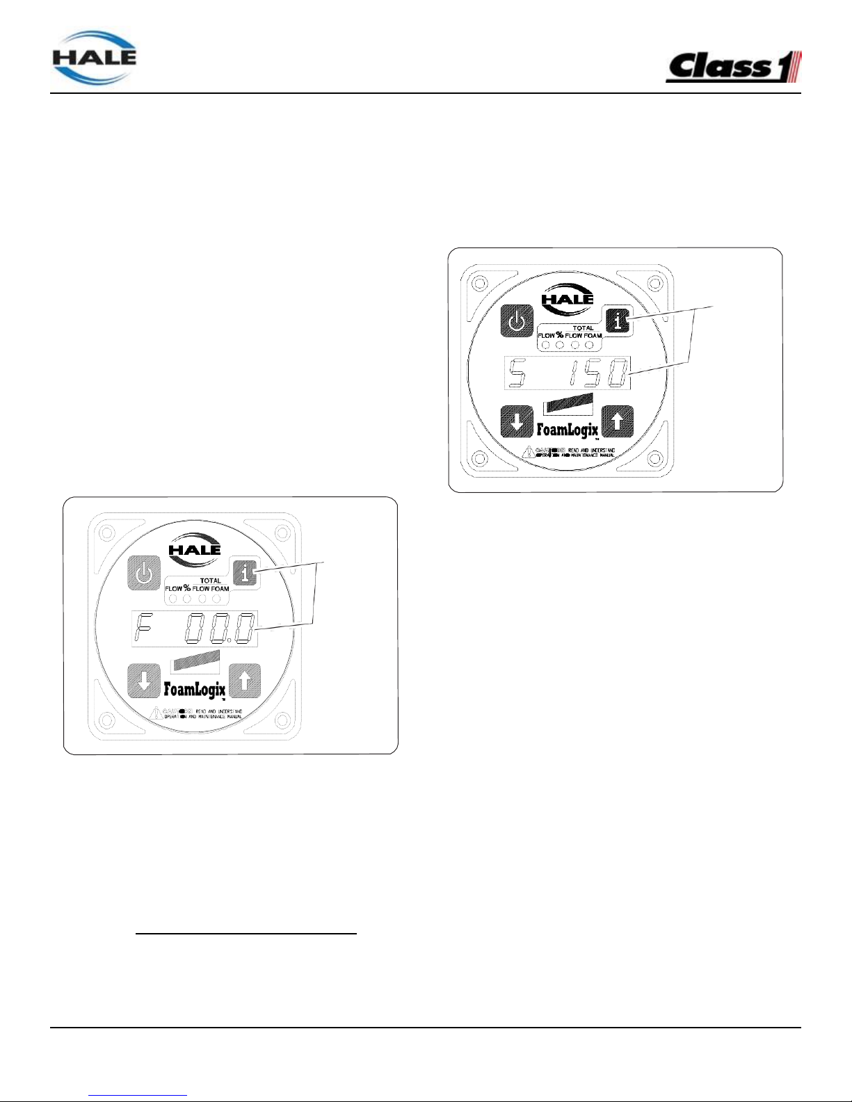
FoamLogix, Model 2.1A and 1.7AHP Class “A”
Electronic Foam Proportioning Systems
55
3.
Press the or button and set the reading to
match the actual flow calculated from the Pitot
gauge reading.
4.
Decrease fire pump pressure by approximately
one half (1/2) and recalculate water flow rate.
Verify the reading on the control unit is within 5%
of the actual value.
5.
STOP the water flow when adjustments are
completed.
SIMULATED FLOW
The default Simulated Flow value is factory set to
150 GPM (568 LPM) and, if necessary, may be
adjusted while in the user calibration mode.
Record Flow and Sensor Calibration Factors
Press and release the i button. The display show
F xx.x, which is the water flow sensor calibration
factor (See Figure 28: “Display Flow Sensor
Calibration Factor.”)
Figure 29: Display - Simulated Flow Calibration
Press the i button. The default simulated flow rate
is shown. (See Figure 29: “Display - Simulated Flow
Calibration.”)
Adjust the setting to the required rate by pressing
the or buttons (e.g., S 150).
FOAM CONCENTRATE INJECTION RATE
Figure 28: Display - Flow Sensor Calibration Factor
Record this value for future reference. This factor
must be programmed into the display if the display is
ever replaced.
WATER FLOW SENSOR CALIBRATION
FACTOR:
When the Hale FoamLogix system power is turned
ON, the foam concentrate injection rate stored in
memory is the default setting. The user specific
default concentrate injection rate is adjusted in
calibration mode.
1.
Press the i button.
The display shows the current default concentrate
injection rate stored in the computer memory for the
selected foam concentrate tank. (See Figure 30:
“Display Foam Concentrate Injection Rate Default
Value” on page 56.)
Press and
release - F xx.x
is shown
Press and
release - CAL is
shown
Page 56
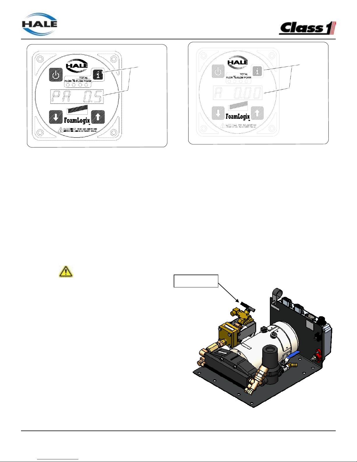
FoamLogix, Model 2.1A and 1.7AHP Class “A”
Electronic Foam Proportioning Systems
56
Figure 30: Display - Foam Concentrate Injection Rate
Default Value
2.
If the factory default values have not been
changed the display shows PA 0.5.
3.
Use the or buttons to set the user specified
default concentrate injection rate.
FOAM PUMP FEEDBACK CALIBRATION
IMPORTANT!
FOAM PUMP FEEDBACK IS CALIBRATED AFTER
INSTALLATION TO VERIFY VALUES WITH THE
ACTUAL FOAM CONCENTRATE(S) BEING USED.
ONLY CALIBRATE USING ACTUAL FOAM CONCENTRATES.
DO NOT USE WATER, TRAINING OR TEST FOAMS
FOR FEEDBACK CALIBRATION VERIFICATION.
1.
Press the i button.
The display shows A x.xx, the total volume of foam
concentrate pumped during the last calibration run.
(See Figure 31: “Display - Foam Pump Feedback
Calibration.”)
2.
Set the bypass valve to the BYPASS.
Figure 31: Display - Foam Pump Feedback Calibration
3.
Place a graduated measure container at the
outlet of the bypass hose capable of containing
the expected volume of foam concentrate, 5
gallons (19 liters) minimum.
(See Figure 32: “Foam Concentrate Collection.”)
Note: If an accurate calibrated container is not
available an accurate scale can be used to
weigh the foam concentrate pumped. The total
volume of foam concentrate is then calculated
from this weight and the density of the foam
concentrate per the MSDS sheet.
Figure 32: Foam Concentrate Collection
Press and
release - the
present value is
shown
Press and
release - the
default value is
shown
Bypass Valve
Page 57
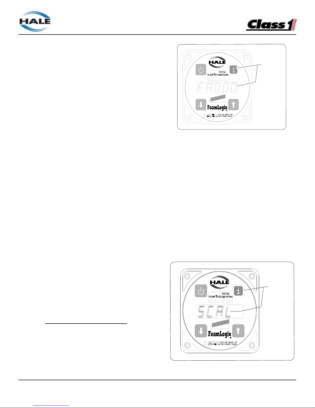
FoamLogix, Model 2.1A and 1.7AHP Class “A”
Electronic Foam Proportioning Systems
57
4.
Start the Hale FoamLogix foam pump by pressing
the red ON button.
The LEDs on the horizontal bar graph lights as
the foam pump begins operating at approximately
two-thirds speed, pumping foam concentrate into
the container.
The display shows the volume of foam
concentrate being pumped.
5.
STOP the foam pump and accurately measure
the amount of foam concentrate collected.
6.
Adjust the reading on the display to match the
volume actually pumped using the or
button.
7.
Repeat the procedure to verify the setting is
correct.
8.
Set the bypass valve handle back to INJECT
position.
Record Foam Pump Feedback Calibration
Factor
1.
Press and release the i button.
The display shows FA xxx,the foam pump
feedback calibration factor. (See Figure 33:
“Display - Foam Pump Feedback Calibration
Factor.”)
2.
Record this value for future reference. This
factor must be programmed into the display if
the display is ever replaced.
FOAM PUMP FEEDBACK CALIBRATION
FACTOR:
Figure 33: Display - Foam Pump Feedback Calibration
Factor
The display show PASS, then clears.
2.
While continuing to hold the display button
enter the password ().
3.
The display shows SCAL for several seconds and
then cycles through the start-up sequence
followed by the flow display O. (See Figure 34:
“Display - Exit and Save Calibration.”)
This completes verification and adjustment of the
system. The Hale FoamLogix system is now ready
to be placed in service.
EXIT AND SAVE CALIBRATION
1.
To exit calibration and save the set values,
press and hold the i button.
Figure 34: Display - Exit and Save Calibration
Press and
release - SCAL
is shown
Press and
release - the
feedback factor
is shown
Page 58
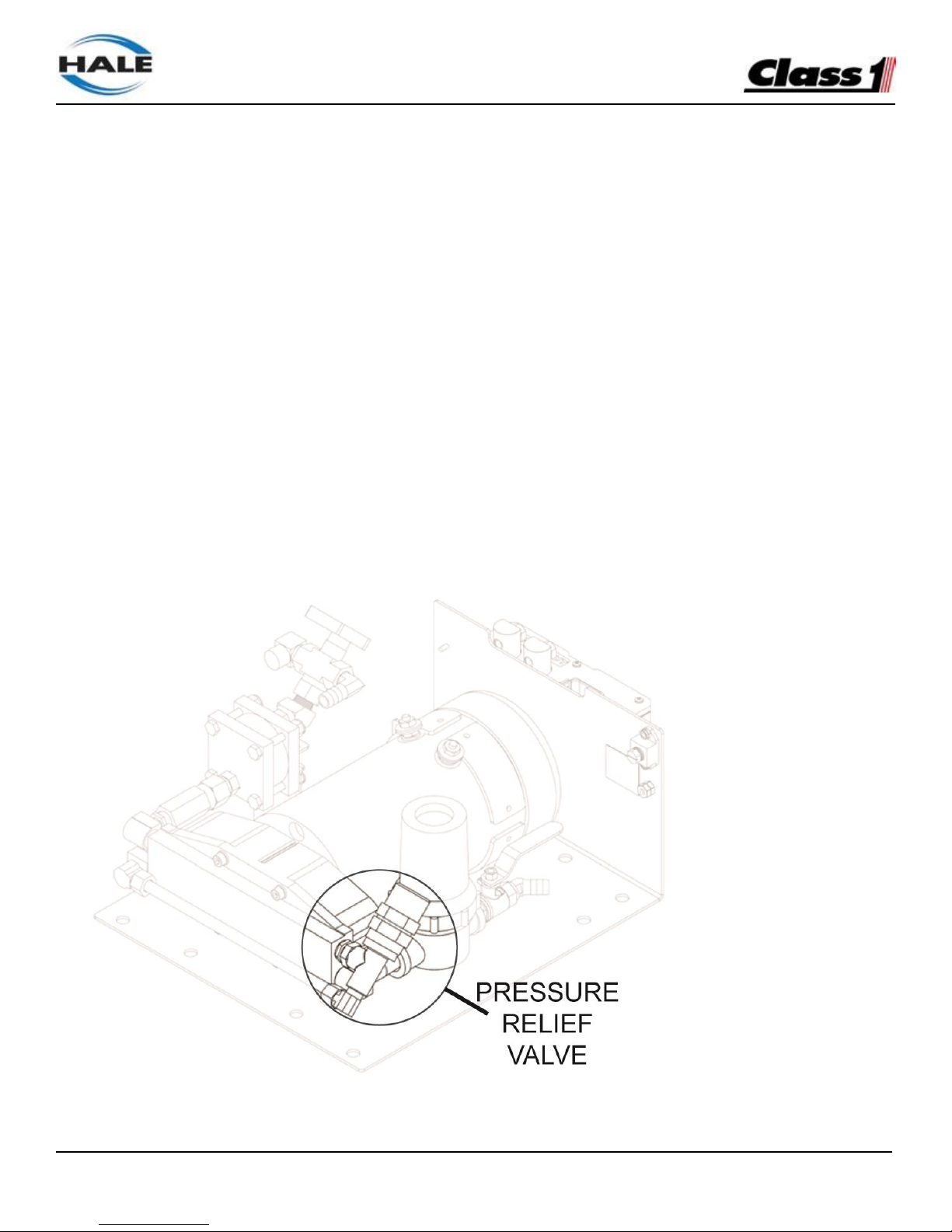
FoamLogix, Model 2.1A and 1.7AHP Class “A”
Electronic Foam Proportioning Systems
58
RELIEF VALVE
The pressure relief valve is factory tested and set to
300 PSI (21 BAR). (See Figure 35: “Relief Valve.”)
During normal installation and operation, the
relief valve does not require adjustment.
If adjustment is necessary during field installation,
contact Hale Products Inc. at 610-825-6300 for
Relief Valve Service information.
ENGLISH TO METRIC UNITS
The FoamLogix Display offers both English and
Metric readouts.
The Hale FoamLogix system is calibrated at the
factory to U.S. measurement (GPM, PSI, GALLONS, etc.) units.
To convert to Metric units:
1. Press and hold the i button. The display show
PASS, then clears.
2.
While continuing to hold the display button enter
the password (
) .
3.
The display shows IN to indicate Metric units are
selected.
Note: Switching to English is accomplished by
repeating Steps 1 through 3. The display shows EN
to indicate English units.
Figure 35: Relief Valve
Page 59
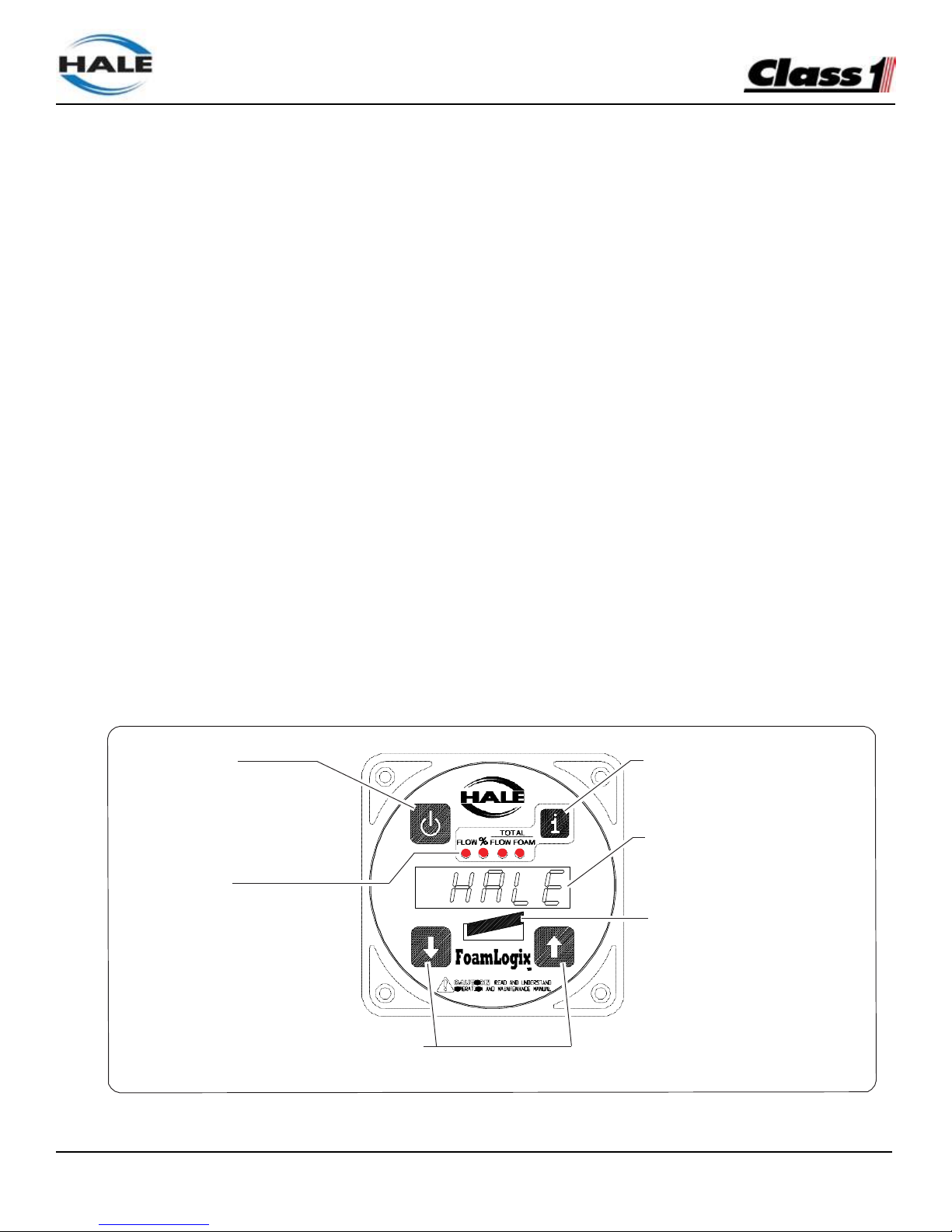
FoamLogix, Model 2.1A and 1.7AHP Class “A”
Electronic Foam Proportioning Systems
59
Section 4 Operation
DESCRIPTION
Operation of Hale FoamLogix systems is controlled
by the Digital Display Control Unit, provided with
four push buttons (pads). (See Figure
36: “Digital Diaplay Control Unit Overview.”)
The Hale FoamLogix system constantly monitors
water and foam concentrate flow values, maintaining
foam injection at the specified concentrate injection
rate. The system responds to variations in water flow
by increasing or decreasing the speed of the foam
pump.
On initial power up of the apparatus, the Hale
FoamLogix system begins a brief self-diagnostic
routine. When completed, the system enters the
STANDBY mode. The FLOW LED lights and the
dsiplay shows the current water flow rate in the
monitored discharge pipe.
Pressing the DISPLAY button (i) cycles through
the four functions as indicated by the red LED
illuminating under each function.
may be reset any time they are displayed. When
the % FOAM LED is lit, or in any other function
mode, the foam concentrate injection rate may
be set to the desired value, if different from the
default value. This may be adjusted prior to or
during foam operations by pressing the and
buttons. Also see heading “Control unit functions”
on page 60.
When the red ON button is pressed, the FLOW
LED illuminates indicating that the system is
ready. If water flow is present the foam pump
starts and injects foam concentrate into the
discharge stream.
The bar graph lights when foam is being injected
and indicates system capacity.
When the ON button is pressed again the LEDs
extinguish, indicating that the system is in STANDBY
mode and the foam pump STOPS. However, other
system monitoring functions continue.
Figure 36: Digital Display Control Unit Overview
Note: TOTAL FLOW and TOTAL FOAM values
On /OFF BUTTON
(Turns Foam Injection ON or OFF.)
SELECT DISPLAY
(Selects control unit function as indicated
by labels and LEDS to the left.)
DIGITAL DISPLAY
(Provides direct readout of selected
function values and shows WARNINGS.)
LED Indicators (4)
(Light ot indicate the function selected.)
BAR GRAPF
(Lights to indicate the system is ON and
the level of injected foam concentrate.)
UP / DOWN ARROWS
(Used to adjust the concentrate injection rate during operation. Pressing both
arrows simultaneously resets the TOTAL FOAM or FLOW Values.)
Page 60
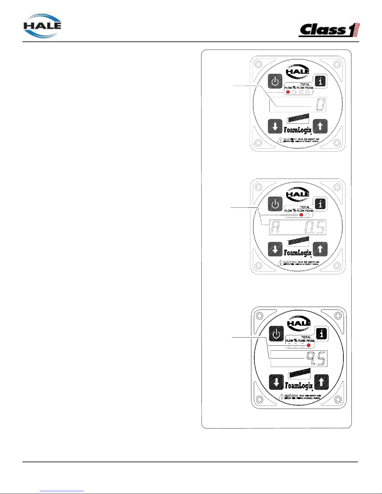
FoamLogix, Model 2.1A and 1.7AHP Class “A”
Electronic Foam Proportioning Systems
60
DISPLAY INFORMATION
The five digit display on the control unit shows
the value of the selected function or provides
WARNINGS to the operator as the system is
operating.
A function is selected by pressing the grey DISPLAY
button (i). Each time the button is pressed a new
function mode is selected and displayed. LEDs
above the digital display denote which function is
selected.
Pressing the DISPLAY button (i) changes the
control unit functions but does not affect injection
rate.
Control Unit Functions
See Figure 37: “Display - Function Modes.”)
FLOW
The display shows the current flow rate of water
or foam solution per minute in Hale flow sensor
monitored discharges.
% FOAM
The display shows the foam concentrate injection
rate setting in the % FOAM mode (e.g., A 0.5).
TOTAL FLOW
The display shows the total amount of water or foam
solution pumped through flow sensor monitored
discharges. This totalized value may be reset - see
heading using procedures outlined in the “Reset
Functions” paragraph.
TOTAL FOAM
The display shows the total amount of foam
concentrate pumped.
Figure 37: Display - Function Modes
STANDBY
mode
Stand-By/Flow Mode
Foam
Percentage
Foam Percentage (%)
Total
Foam
Total Foam
Page 61

FoamLogix, Model 2.1A and 1.7AHP Class “A”
Electronic Foam Proportioning Systems
61
The value is in the same unit of measure as the
water flow. This totalized value may be reset - see
heading “Reset Function”.
For example, the display may show 9.5,
indicating 9.5 gallons (36 liters) of foam
concentrate have been used. (See Figure
37: “Display - Function Modes” on page 60.)
Bar Graph
The bar graph consists of a ten (10) LED array.
When the ON button is pressed the left-most LED
lights to indicate the system is ON and ready to
inject foam concentrate.
When water is flowing, LEDs to the right on the bar
graph light indicating foam concentrate is being
injected. The amount of LEDs lighted provides an
indication of the approximate pump capacity being
used.
If water flow requirements exceed the capacity of
the pumps ability to deliver foam concentrate, pump
speed increases to the maximum rate. All bar graph
LEDs light and the right-most LED flashes, warning
the operator that the system capacity is being
exceeded and is running “lean” on foam concentrate
percentage.
If the flow decreases such that the required
injection rate is less than the lowest rating of the
pump, pump spped decreases to its minimum
rate and the first bar graph LED to the left flashes,
warning the operator that the system capacity
is being exceeded and is running “rich” on foam
concentrate percentage.
RESET FUNCTIONS
The totalized values for water and foam concentrate pumped are cleared from memory by
performing a RESET function.
1 Using the DISPLAY button (i), select either TOTAL
WATER or TOTAL FOAM.
2 By pressing and holding both the and buttons
at the same time, the value shown is cleared and the
display shows zero (0).
3 Additionally the totalized values for water and foam
concentrate reset to zero automatically when the
apparatus power is turned OFF.
FOAM CONCENTRATE INJECTION RATE
When % FOAM is selected, the and buttons
respectively increase or decrease foam concentrate
percentage.
While operating in any function, with the exception of FLOW during simulated flow operation,
whenever the or buttons are momentarily
pressed, the display switches to the % FOAM
display and shows the current injection rate for 2
seconds.
In any display mode, if either the or button is
held down for a period of 2 seconds or more, the
injection rate value increases or decreases
accordingly. Once released, the display returns to
the last selected display after 2 seconds.
When a reset is performed in the % FOAM display
mode, the foam concentrate injection rate returns to
the default value.
WARNING MESSAGES
Several safety features are incorporated into
the Hale FoamLogix system to protect the foam
concentrate pump, electric motor and apparatus
wiring while maintaining personnel safety.
Messages appearing on the display alert the
Page 62
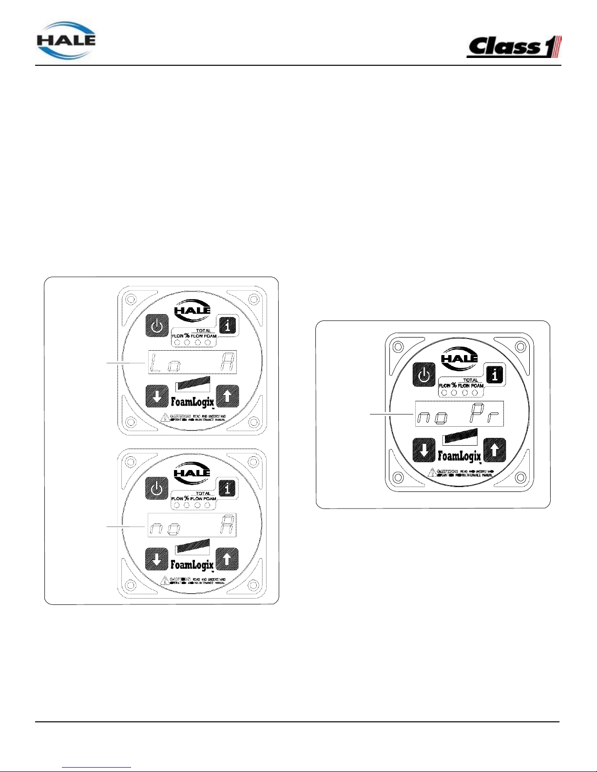
FoamLogix, Model 2.1A and 1.7AHP Class “A”
Electronic Foam Proportioning Systems
62
operator to adverse conditions that could cause
damage to Hale FoamLogix system components,
the apparatus and cause personnel injury.
Low Foam Tank Level
The Hale FoamLogix foam pump is interlocked with
the foam concentrate tank level switch. If the tank
is empty, the pump runs for 1 minute. The
low foam concentrate tank level message is shown
(Lo A)alternating with the normal selected function
on the display. See Figure 38: “Display Low Foam
Tank Display.”
If the ON button is pressed before refilling the
foam tank, the system runs for 30 seconds before
shutting down again.
Priming Error
In the event there is no feedback signal being
received when the foam pump starts, indicating a
lack of foam concentrate flow, the foam pump motor
runs at full speed attempting to establish foam
concentrate flow.
If the system operates for a period of 45 seconds
without a feedback signal the system switches to
the STANDBY mode and the display flashes no Pr
(no prime) indicating there is no foam concentrate
flow. (See Figure 39: “Display - Priming Error.”)
Figure 39: Display - Priming Error
High Ambient Temperature
Figure 38: Display - Low Foam Tank
If one minute of low concentrate level is detected
the display shows no A, and the pump STOPS.
The left-most LED turns OFF until the foam level is
restored and the ON button is pressed.
If the Hale FoamLogix system is operating in an
environment of excessive ambient temperatures,
the display shows HIGH.
If the circuitry in the Hale FoamLogix system is
being affected by a drop in power supply voltage
the display shows Lo SP.
See Figure 40: “Display - High Temperature and
Low Battery” on page 63.
No Prime
(No Flow
Conecntrate Flow)
LOW Foam
Concentrate
After one
Minute of
LOW Foam
Concentrate
Page 63
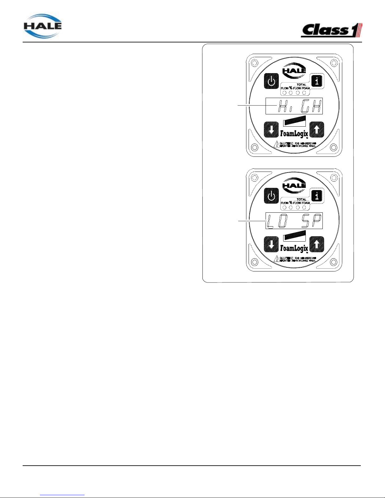
FoamLogix, Model 2.1A and 1.7AHP Class “A”
Electronic Foam Proportioning Systems
63
Note: This is not necessarily an indication of
apparatus battery level or condition. It is only
an indication of adverse operating conditions.
For instance a bad battery cable can cause
the system to see low power even though the
batteries are fully charged.
In either case the system continues to run. If
conditions deteriorate to the point of potential
system damage, due to heat or low power, the
system returns to the STANDBY mode and
the error message remains until ON is pushed
again.
PRIMING THE FOAM PUMP
(When the Foam Tank Runs Dry)
In some instances, the foam tank may run dry
while operating the Hale FoamLogix system. The
foam pump is designed to pump liquid. When the
fire pump is running the foam pump may not pump
efficiently against 100 to 150 PSI (7 to 10 BAR)
back pressure. To re-establish foam concentrate
flow quickly the following procedure is used.
1.
Turn the bypass valve to the BYPASS position.
2.
With the fire pump flowing water from foam
discharge and the Hale FoamLogix ON,
observe the hose from the bypass valve.
3.
When foam concentrate flows from the hose
turn the bypass valve back to the INJECT
position.
The pump is now primed and ready for
normal operation.
Figure 40: Display - High Temperature and Low Battery
Excessive
Temperatures
Power
Reduction
(Low Battery)
Page 64
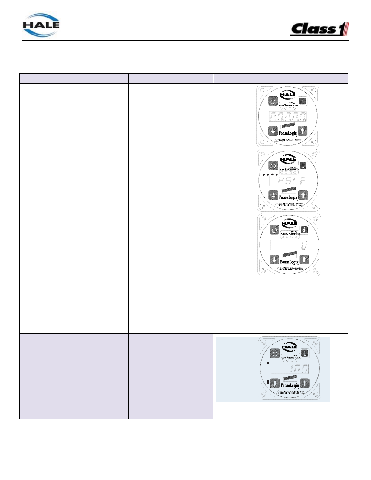
FoamLogix, Model 2.1A and 1.7AHP Class “A”
Electronic Foam Proportioning Systems
64
NORMAL OPERATION SUMMARY
OPERATION
ACTION
DISPLAY
Energize the system
Select foam tank
Energize apparatus and
turn FoamLogix power
switch to ON.
If System equipped with
dual foam tanks place
selector toproper tank.
Initial StarUp
Self Diagonstics
STANDBY Display
(Single Flow Sensor: FLOW MULTIPLE
Flow Sensor: % FOAM)
Begin foam injection
Establish water flow and
press ON button.
Water Flow
Established
(ON Button Pressed)
Page 65
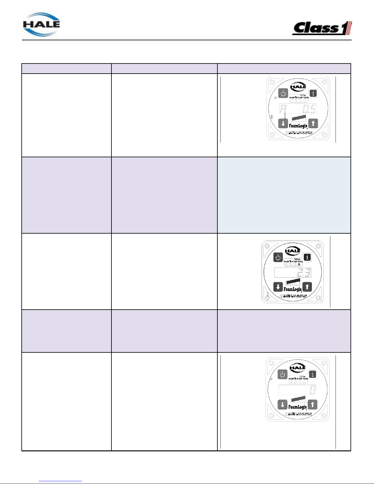
FoamLogix, Model 2.1A and 1.7AHP Class “A”
Electronic Foam Proportioning Systems
65
OPERATION
ACTION
DISPLAY
Change injection rate
Read injection rate
Press or and hold for 2
seconds. Release once rate is
set.
Press and release or
Display shows injection rate and
returns to selected function after
2 seconds.
Foam
Concentrate
Injecion Rate
Read total water or foam
solution
Press i until LED below TOTAL
FLOW turns ON.
Total
Flow
Read total foam
concentrate
Press i until concentrate LED
below TOTAL FOAM turns ON.
Total
Foam
Reset totalized values
While in TOTAL FLOW or TOTAL
FOAM press and release and
End foam injection
Press ON button.
STANDBY MODE
(Single flowsensor: Flow multiple Flow sensors:
% FOAM)
Page 66
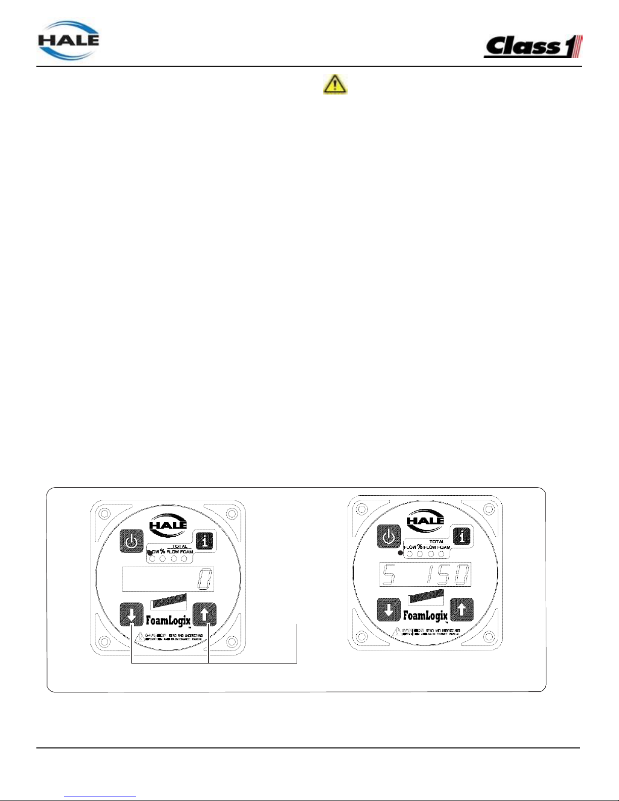
FoamLogix, Model 2.1A and 1.7AHP Class “A”
Electronic Foam Proportioning Systems
66
SIMULATED FLOW OPERATION
CAUTION!
The Simulated Flow mode of the Hale FoamLogix
system allows operation of the foam pump without
discharging water through a foam capable discharge
or when the flow sensor is not functioning.
The simulated flow mode is used for draining the
foam tank for:
❑ Cleaning
❑ Checking calibration of the feedback sensor
❑ Verifying foam pump operation
❑ Manually controlling foam injection if the flow
sensor malfunctions.
The factory default simulated flow rate is 150
GPM (568 LPM). The simulated flow rate and the
concentrate injection percentage rate are set by the
rate adjustment buttons on the control unit display,
while in simulated flow mode.
The simulated flow function provides manual
operation of the foam injection system required by
NFPA standards.
WHEN OPERATING THE HALE FOAMLOGIX IN
SIMULATED FLOW MODE AN OUTLET FOR THE
FOAM CONCENTRATE MUST BE PROVIDED TO
PREVENT EXCESSIVE PRESSURE BUILDUP IN
DISCHARGE PIPING OR HOSES.
Simulated flow sequence
1.
Uncoil and place the end of the bypass hose
into a suitable container to collect the foam
concentrate.
2.
Place the BYPASS valve in the BYPASS
position.
3.
Energize the apparatus electrical system and
press Hale FoamLogix power button ( i ) to turn
ON the system.
4.
The Hale FoamLogix enters the STANDBY
mode. (See Figure 41: “Display - Simulated
Flow Operation.”)
Figure 41: Display - Simulated Flow Operation
Simultaneously
PRESS and RELEASE
Diaplay - Entering Simulated Flow Mode
Diaplay - Simulated Flow Mode
Page 67

FoamLogix, Model 2.1A and 1.7AHP Class “A”
Electronic Foam Proportioning Systems
67
1 When the FLOW LED lights, press and release
the and buttons at the same time.
2 The display shows S 150 (or other preset default
value) and the FLOW LED lights. (See Figure
41: “Display - Simulated Flow Operation” on
page 64.)
3 Press the ON button. The left-most LED on
the bar graph lights and the foam pump begins
running.
Foam concentrate flows out of the end of the
bypass hose.
To End Simulated Flow
1.
First press the ON button to STOP the foam
pump.
2.
Press the i button until the FLOW LED
lights.
3.
Press and release the and buttons
at the same time. The display shows the
current water flow value and the FLOW LED
lights.
4.
De-energize the apparatus electrical system.
5.
Place the bypass valve to the INJECT
position.
6.
Secure bypass hose in the appropriate
compartment.
7.
Return apparatus to normal ready condition.
Page 68

FoamLogix, Model 2.1A and 1.7AHP Class “A”
Electronic Foam Proportioning Systems
68
NOTES
Page 69

FoamLogix, Model 2.1A and 1.7AHP Class “A”
Electronic Foam Proportioning Systems
69
SECTION 5 MAINTENANCE
MAINTENANCE PROCEDURES
1.
After each use
Inspect wiring, hoses, flow sensors and
connections for tightness, corrosion, leaks and.
or damage. Refer to Figure 3 on page 21.
Flush foam pump if a non-approved foam
concentrate is used. Also see appendix A, “Hale
Foam concentrate Compatibility” beginning on
page 87 for recommended foam concentrates.
2.
Monthly
Remove and clean the foam strainer screen.
Flush as required.
3.
Monthly
Verify water flow calibration.
4.
Annually
Verify foam feedback calibration.
5.
Every two (2) months
If an approved foam concentrate has been left in
the system, operate foam system to remove the
foam concentrate and prevent jelling.
FREEZE PROTECTION
Cold weather transport and cold weather storage of
FoamLogix systems:
• When transporting the completed fire
apparatus from the OEM to the dealer, and
the dealer to the end-user, or, when the enduser decides to store the finished apparatus
in an unheated area subject to below freezing
temperatures, a FoamLogix winterization
process must be used.
• Any water and/or foam concentrate that
is in the foam concentrate reservoir, foam
concentrate pump, and associated foam
system piping/tubing will freeze and then
break system components when the system
is subjected to subfreezing temperatures
commonly found in over-the-road driving
during fire truck delivery and transport. The
following precautions must also be taken
by OEMs, end-users, re-sellers, fire truck
dealers, transport agencies, etc., that will be
transporting and/or storing the apparatus in
below freezing temperatures:
o Drain the foam concentrate storage
reservoir in accordance with safe foam
concentrate handling practices as outlined
by the foam concentrate manufacturer. If
the foam reservoir is filled with only water,
completely drain the storage compartment
of water. After empty, close all drain valves.
o Pour in five gallons (18.93L) of an
appropriate antifreeze solution in the foam
concentrate reservoir. Consider using an
environmentally friendly biodegradable
formulation.
o Follow the Installation and operation manual
procedure to “prime” the foam pump.
o With the apparatus fire pump in gear, a
water supply established, and a discharge
hose and nozzle attached to the discharge
side of the fire pump, discharge over
100-gpm (380 LPM)from a foam capable
discharge.
o Turn the FoamLogix system “on.” Depress
the “up” arrow and raise the proportioning
rate to 3.0%.
o Continue to discharge water out of the
discharge hose for one-minute.
o Shut the FoamLogix system “Off.”
o Shut off the discharge valve and shut the
fire pump down. Remove the water supply
connection to the fire pump.
Page 70

FoamLogix, Model 2.1A and 1.7AHP Class “A”
Electronic Foam Proportioning Systems
70
o Drain the fire pump, valves and fire pump
system accessories.
The foam system is now winterized and ready
for cold weather duty transport and/or cold
weather storage.
After transport, prior to the placing the unit in
service:
• Drain the foam concentrate reservoir of antifreeze in an environmentally friendly fashion.
• Shut all foam reservoir drain valves.
• Fill the foam reservoir with a Hale approved
compatible Class A foam concentrate.
• Establish a water supply to the fire pump and
install a discharge hose and nozzle.
• Operate the fire pump and discharge 100gpm (380 LPM) of water from a foam capable
apparatus discharge. Be sure to collect the
discharge in an area, to be cleaned-up later,
to mitigate any environmental impact that the
anti-freeze / foam solution may cause.
• Turn the foam system “on.”
• Depress the “up” arrow and raise the foam
injection rate to 3.0%.
• Operate the discharge hose for one minute.
• Shut the foam system “off.” Turn the fire
pump “off.” Remove the hose and nozzle.
Disconnect the water supply.
• The unit is now ready for service.
Page 71
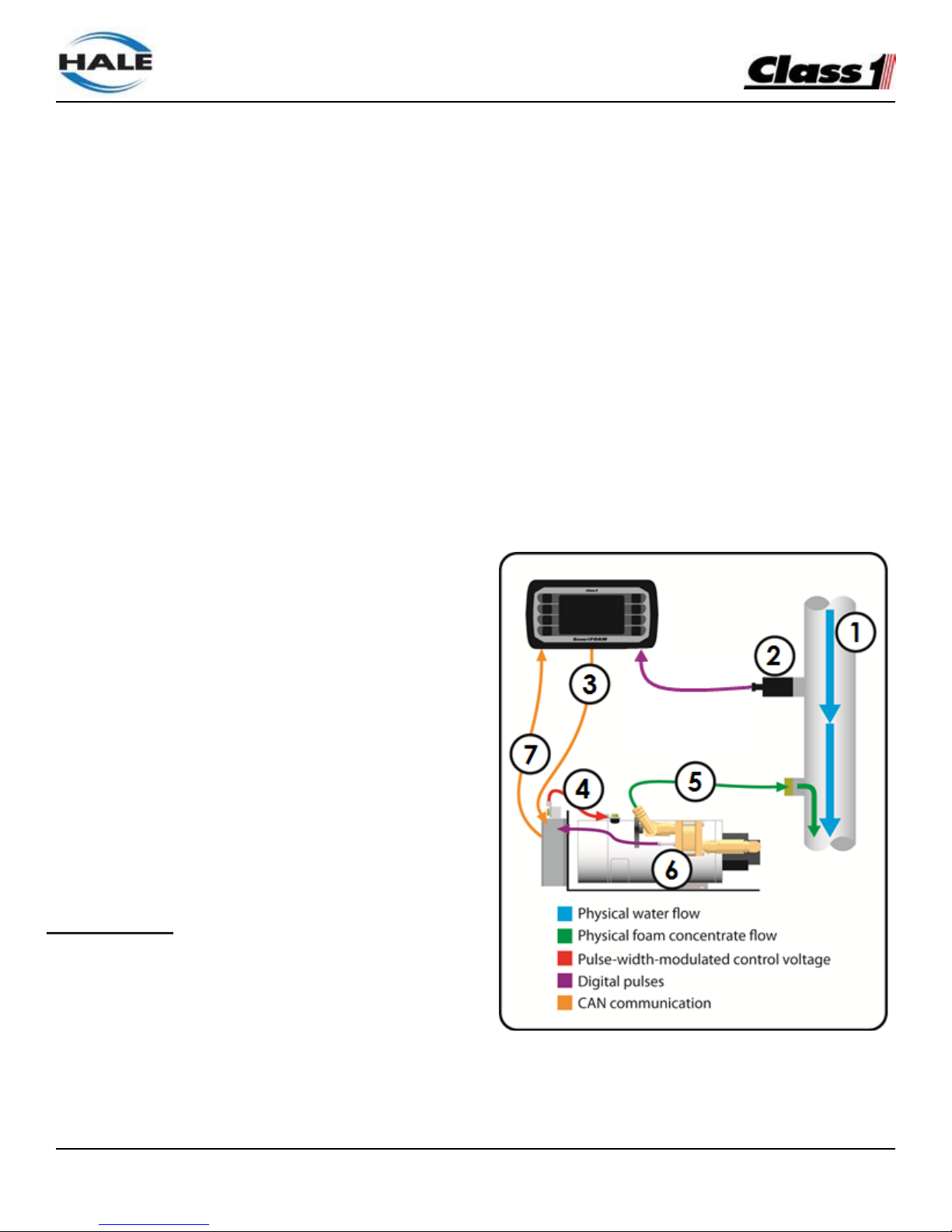
FoamLogix, Model 2.1A and 1.7AHP Class “A”
Electronic Foam Proportioning Systems
71
SECTION 6 TROUBLESHOOTING
USER DIAGNOSTICS
Diagnostic LED indicators are provided on the distribution
box and on the feedback sensor. The LED on the feedback
sensor flashes when the sensor is receiving pulses from the
flow sensor rotor targets. These LEDs help to ease tracing of
power supply faults and eliminates some of the guesswork
in troubleshooting. If the system malfunctions make sure the
following conditions are checked:
❑ All hose connections are correct and tight (Refer to
appropriate system plumbing diagram in the
INSTALLATION section).
❑ All electrical connections are correct and tight (Refer
to appropriate system electrical diagram in the
INSTALLATION section).
❑ Apparatus electrical system energized with power
supplied to pump panel and Hale Foamlogix
controller.
Once the above conditions are met, proceed to the system
troubleshooting section to determine the cause of the
malfunction.
Hale Foamlogix systems consist of individual subsystems
working together to provide finished foam solution at the
proper percentage. Also see the SYSTEM OVERVIEW
section.
The system is designed using modular components making
troubleshooting and repair easier. Each subsystem has its
own set of troubleshooting procedures. The procedures that
follow provide a logical flow path to isolate and correct a
system failure.
Note: Hale Foamlogix system electronic components have
no user serviceable components inside and are replaced as
a unit. Opening of Hale Foamlogix electronic components
voids the manufacturer warranty.
System Overview
The Foamlogix proportioner is a closed-loop system. The
“brain” behind the system is the computer-controlled
Foamlogix Controller Display. A basic understanding of how
the system functions makes troubleshooting easier (refer to
Figure 1: Closed Loop Control Diagram while reading the
following control steps).
1. Water flows through the discharge manifold and past
the water flow sensor spinning its paddlewheel.
2. The water flow sensor sends the raw digital pulses
to the Foamlogix controller display.
3. The Foamlogix controller display calculates the
desired foam flow rate based on the water flow rate
and the currently set foam concentrate percentage.
The Foamlogix controller display transmits a
requested motor rate (0% to 100%) to the
distribution box via CAN communication.
4. The distribution box sends pulse-width-modulated
control voltage (0% to 100%) to the motor which
turns the pump at the desired speed.
5. The pump begins discharging foam concentrate into
the discharge manifold where it mixes with the
water.
6. The foam sensor detects the foam concentrate
flowing past the target rotors and sends the raw
digital pulses to the distribution box.
7. The distribution box sends the foam flow rate to the
Foamlogix controller display where it is evaluated
and the process starts again at step 1.
Figure 1: Closed Loop Control Diagram
Note: The Foamlogix system has a simulated flow function
described in the SIMULATED FLOW OPERATION section.
This allows troubleshooting without flowing water yet
simulates an actual water flow.
Page 72
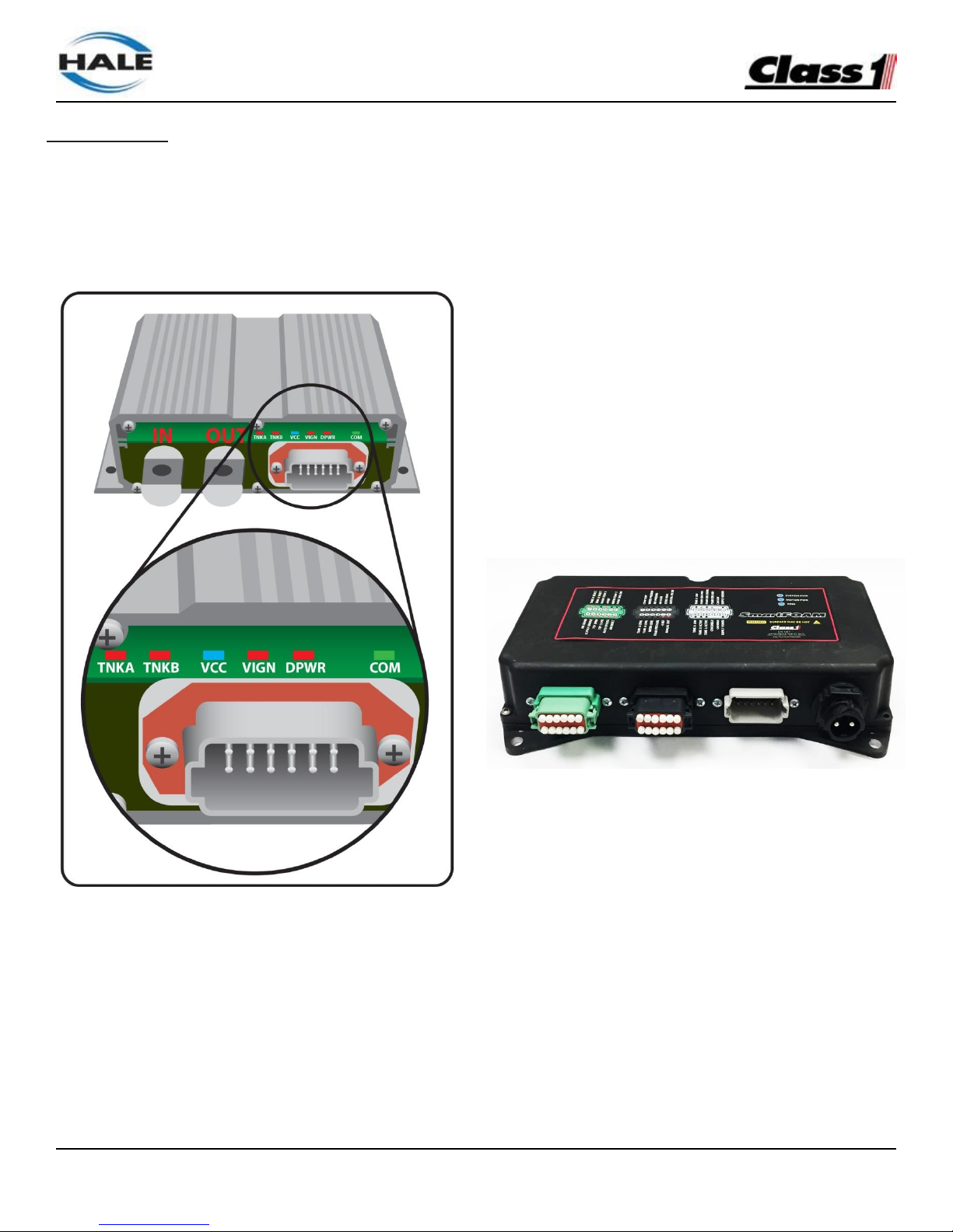
FoamLogix, Model 2.1A and 1.7AHP Class “A”
Electronic Foam Proportioning Systems
72
Distribution Box
The Distribution Box (part of the pump/motor assembly)
controls the speed of the pump/motor based on commands
from the Foamlogix controller display. The distribution box
also receives the signal from the foam feedback sensor, low
tank sensor(s), and tank selector and relays that information
back to the Foamlogix controller display.
Figure 2: Distribution Box LEDs
The distribution box contains six internal LEDs to help with
diagnostics (refer to Figure 2: Distribution Box LEDs).
❑ TNKA is illuminated when the tank selector is set to
“tank A”. This is based on a physical input into pin 4
of the gray connector on the front of the distribution
box. (When the TNKA and TNKB LEDs are OFF the
system is in FLUSH mode).
❑ TNKB is illuminated when the tank selector is set to
“tank B”. This is based on a physical input into pin 5
of the gray connector on the front of the distribution
box. (When the TNKA and TNKB LEDs are OFF the
system is in FLUSH mode).
❑ VCC is illuminated when power and ground are
applied to the distribution box’s pins 1 and 12. This
indicates that the internal 5 volt regulator is
functioning for the internal components.
❑ VIGN is illuminated when power and ground are
applied to the distribution box’s pins 1 and 12. This
indicates that system power and ground are
recognized within the unit.
❑ DPWR is illuminated when the “IN” power stud is
energized with system voltage. This power is
required to drive the motor attached to the pump.
❑ COM is illuminated when the distribution box is
communicating with the Foamlogix controller display
via the CAN. This LED with be flashing if there is a
CAN communication problem and it cannot
communicate with the Foamlogix controller display.
If no tank selector (MST, MDTII, ADT) is used a connector
plug is installed to connector C8 to lock the system in the
Tank A mode. Removing this plug or disconnecting the tank
selector cable places the system in the FLUSH mode.
Figure 3: 610-00044 New Distribution Box
The distribution box was upgraded Fall 2017 to 610-00044.
This new distribution box has improved protection against
overcurrent. There are three inputs (green, black, and grey),
but only the grey is utilized for foam units. The black
connector is power. There are three standalone indicator
lights on the top of the case:
❑ SYSTEM PWR is illuminated when the “IN” power
stud is energized with system voltage. This power is
required to drive the motor attached to the pump.
❑ MOTOR PWR is illuminated when there is power
output to the foam motor.
❑ COM is illuminated when the distribution box is
communicating with the Foamlogix controller display
via the CAN. This LED with be flashing if there is a
CAN communication problem and it cannot
communicate with the Foamlogix controller display.
Page 73
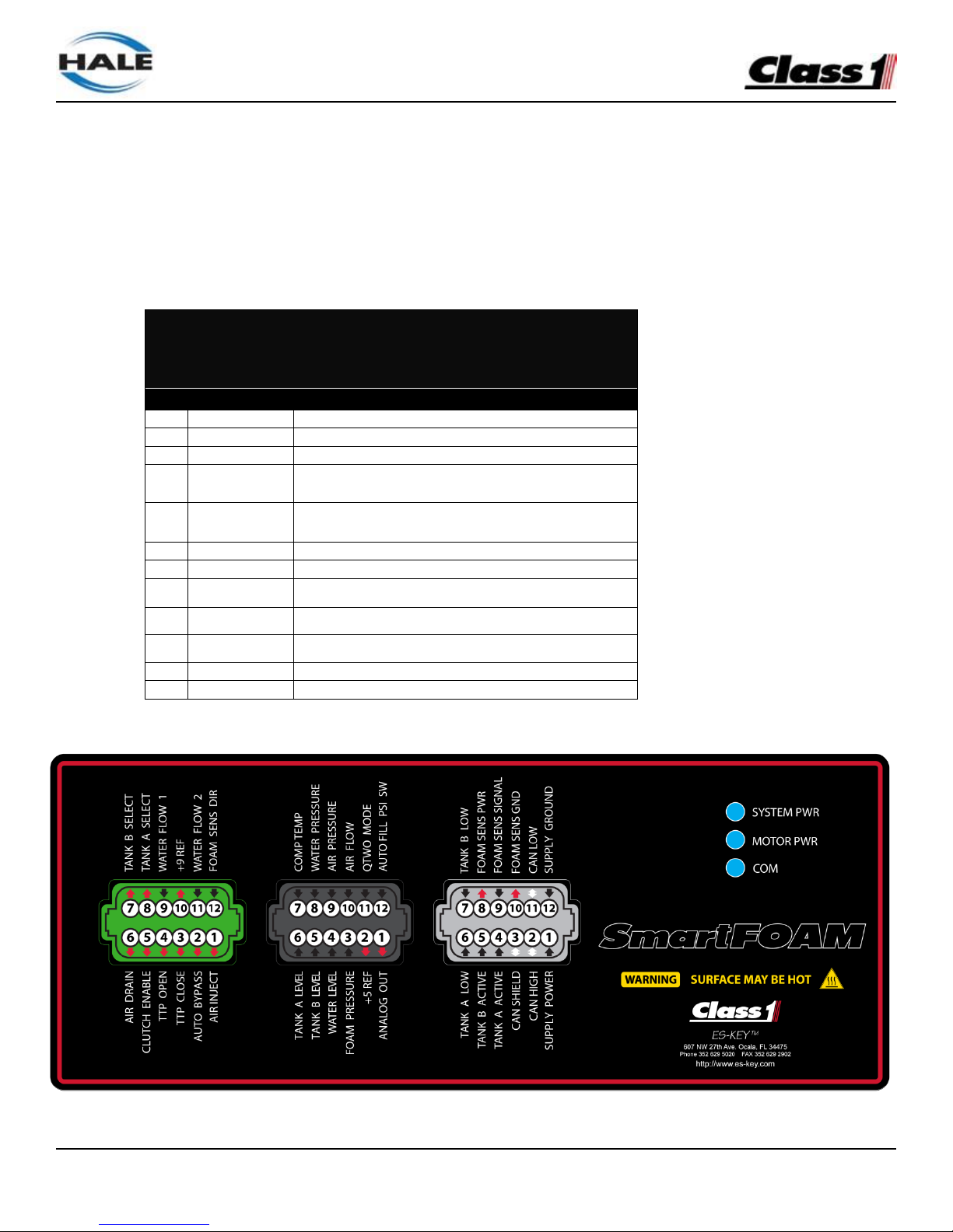
FoamLogix, Model 2.1A and 1.7AHP Class “A”
Electronic Foam Proportioning Systems
73
The COM LED indicates the module’s CAN communication status.
On Solid = Module on-line
Flashing slow (2Hz) = CAN bus okay, but the module is not receiving messages from the Foam Controller.
Flashing fast (8Hz) = CAN bus error, no communications.
Gray connector (this connector is the same between the old and new motor drivers)
Mating connector: Deutsch DT06-12SA GRAY
Mating sockets: Deutsch 0462-201-16141
Gold mating sockets: Deutsch 0462-201-1631
Recommended wire gage: 16-20 AWG
Wedge lock: W12S
PIN
CIRCUIT
DESCRIPTION
1
SYS POWER
(INPUT) – Battery voltage (+9VDC…+32VDC)
2
CAN HIGH
(DATA) – SAE J1939 CAN 2.0B, 250Kbits/s
3
CAN SHIELD
(DATA) – SAE J1939 CAN 2.0B, 250Kbits/s
4
TANK A ACTIVE
(INPUT) – Positive polarity
5
TANK B ACTIVE
(INPUT) – Positive polarity
6
TANK A LOW
(INPUT) – Positive polarity
7
TANK B LOW
(INPUT) – Positive polarity
8
FOAM SENS PWR
(OUTPUT) – Reference voltage for foam sensor (battery power)
9
FOAM SENS SIG
(INPUT) – Positive pulse signal
10
FOAM SENS GND
(OUTPUT) – Battery ground
11
CAN LOW
(DATA) – SAE J1939 CAN 2.0B, 250Kbits/s
12
SYS GROUND
(INPUT) – Battery ground
Pump/Motor
Figure 4 610-00044 pinouts
Page 74
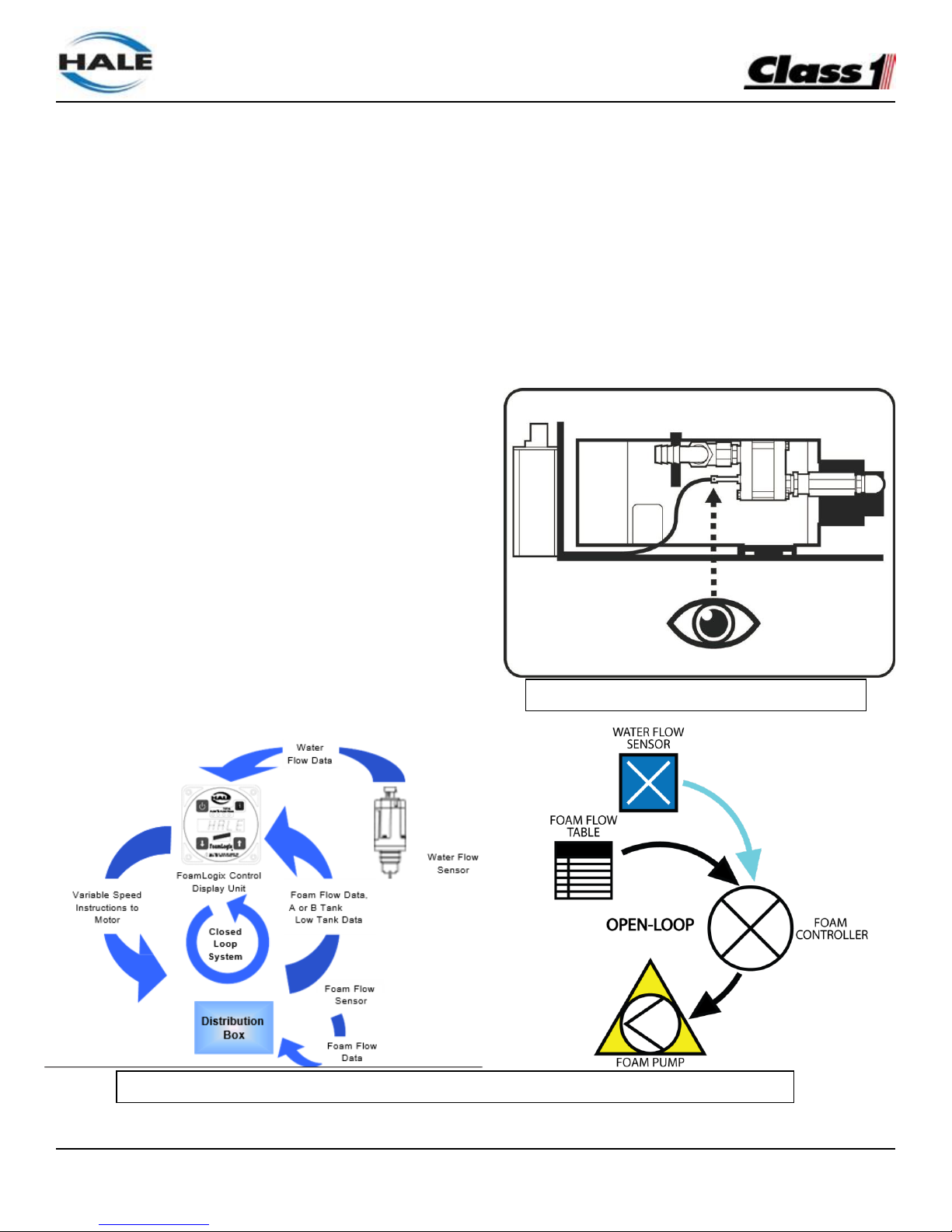
FoamLogix, Model 2.1A and 1.7AHP Class “A”
Electronic Foam Proportioning Systems
74
System Overview
See Figure 43: “FoamLogix 2.1A and 1.7AHP System
Closed-Loop Flow Diagram.”
The FoamLogix 2.1A and 1.7AHP are “closed- loop”
systems. The brains behind the system is the
computer-controlled FoamLogix Control Display Unit.
As an electronic system, the flow of data ”runs“ the
system. A basic understanding of how the system
functions makes troubleshooting easier.
Water flow data is fed to the control unit computer. Since
the injection rate (%) is preset, the control unit
calculates the required motor speed of the foam pump
and sends this data to the motor. The output of the pump
is measured by a foam flow feedback sensor.
The discharge of the foam pump directs foam to the rotary
lobe flow meter. The rotors are a composite material
containing small stainless steel targets. As the foam is
being pumped these targets are detected by the inductive
sensor which sends pulses to the distribution box. An
LED indicator on the inductive sensor flashes as a target
passes the tip of the sensor. The speed of the foam being
pumped determines how quickly the rotors are turning and
how quickly the inductive sensor’s LED flashes (which
could be so fast that the indicator light actually appears to
be constant).
The foam flow feedback sensor tells the control unit how
much foam is actually pumped so the display can make
the required motor speed adjustments. This closed-loop
runs several times per second and is what makes the
system so accurate. If the sensor does fail then the
system enters into “open-loop” or limp mode. The OpenLoop Operating Mode uses a precisely engineered table
of pump speed versus foam flow rate. If the foam
feedback sensor should fail the system uses this table in
place of the sensor data to keep the foam system
operating as accurately as possible until the unit can be
serviced.
Note: The FoamLogix unit has a “simulated flow“ function,
described in Section 4: “Operation” heading “Simulated
Flow Operation“ beginning on page 66. This allows
troubleshooting without flowing water, yet simulates an
actual water flow.
Figure 43: “FoamLogix 2.1A and 1.7AHP System Closed-Loop and Open Loop Flow Diagram.”
Figure 42: Flow Sensor Location
Page 75

FoamLogix, Model 2.1A and 1.7AHP Class “A”
Electronic Foam Proportioning Systems
73
Bar Graph
The bar graph on the control display unit, indicates
the system capacity and is a good troubleshooting
tool.
If the display does not see foam feedback data
indicating foam is being pumped, the bar graph
lights all segments and “flashes.” The display runs
the pump fast attempting to prime it and achieve
the proper foam concentrate flow.
If the display does not receive data that foam
concentrate is flowing, it displays the “No Pri”
error message, indicating no prime, and turns the
system OFF. Pressing ON starts the cycle again.
There must be water flow or the unit must be in the
simulated flow mode. Operation of the bar graph
and no prime warnings are discussed in Section 4,
“Operation”.
Summary
Starting with the troubleshooting charts (see Figure
44: “Hale FoamLogix System Troubleshooting Flow
Diagram,” to show the flow data, a field problem
can be traced to a particular component for
replacement.
FoamLogix replacement parts are “plug andplay” type devices that do not require specialized
equipment to service. Normal water flow and
foam calibration is usually necessary after a major
component service.
PROBLEM ISOLATION
The first step in troubleshooting is to determine
which subsystem caused the system failure. To
make this determination operate the apparatus
and Hale FoamLogix system in accordance with
standard operating procedures and isolate where
the problem occurs.
See Figure44: “Hale FoamLogix System Troubleshooting Flow Diagram,” beginning on page 74,
to assist in isolating the cause. Also review the
following steps.
1.
Setup the apparatus for normal operation.
2.
Power-up the apparatus and energize the
pump operator panel. Take notice of the
Hale FoamLogix control unit. If the display is
NOT illuminated proceed to Figure 44: “Hale
FoamLogix System Troubleshooting Flow
Diagram,” beginning on page 74.
3.
If the Hale FoamLogix control unit is illuminated,
engage the apparatus water pump and establish
discharge. If water flow CANNOT be established,
troubleshoot the water pump system.
4. If there is no indication of water flow on the
control unit display troubleshoot the flow sensor.
5. If water flow is established, turn the Hale
FoamLogix system ON to flow foam.
6.
Observe foam pump discharge. If foam is NOT
flowing troubleshoot the foam pump.
7.
Check accuracy of system using calibration
procedures in Section 4 “Operation” of this
manual, making adjustments as required.
Page 76
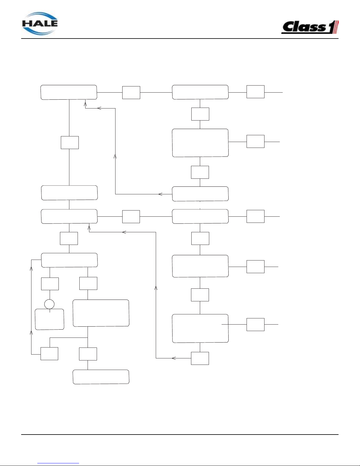
FoamLogix, Model 2.1A and 1.7AHP Class “A”
Electronic Foam Proportioning Systems
74
Chart 44: Hale FoamLogix System Troubleshooting Flow Diagram
TROUBLESHOOTING CHARTS
Is Display Lit?
Is Power Available at
NO
Connector C5?
PROVIDE
NO
POWER
YES
YES
display. Check for
power at Term/ 1.
Is Power Available?
REPLACE
NO
HARNESS
YES
Establish Water Flow
Replace Display
Is Water Flow Value
Displayed?
NO
Is Foam Discharge
OPEN?
OPEN FOAM
NO
DISCHARGE
YES
YES
Is Foam Concentrate
being Injected?
Check Harness
Connection
OK ?
RECONNECT
NO
OR REPLACE
HARNESS
YES
NO
1
Continued -
See 1 on
next Page.
Press ON Button.
Does Motor Run?
YES
Verify Water Flow
Sensor Operative.
Is Sensor operating
correctly?
RECONNECT
NO
WATER FLOW
SENSOR
YES
NO
YES
Check LEDs on
Controller Box
Figure 44: Hale FoamLogix System Troubleshooting Flow Diagram
Page 77
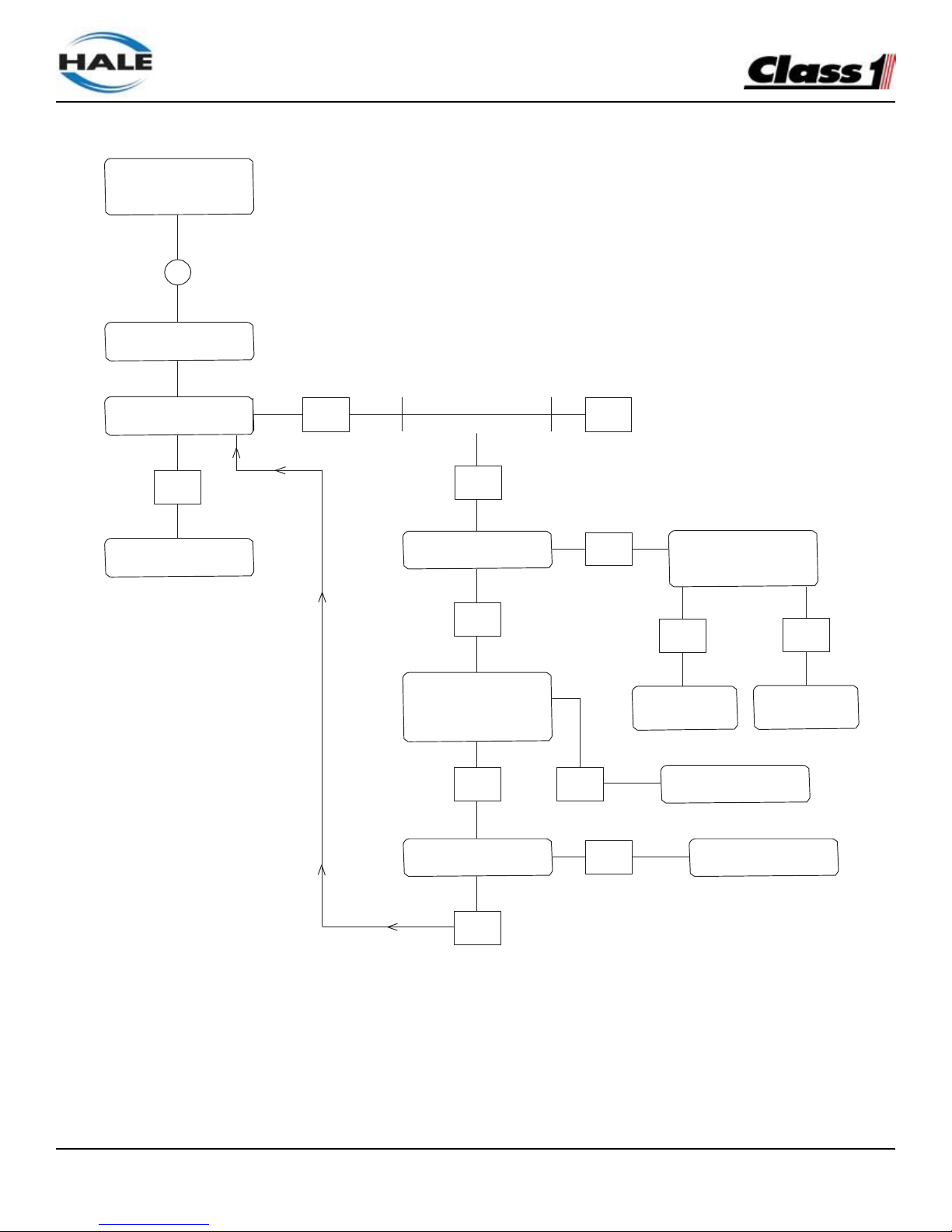
FoamLogix, Model 2.1A and 1.7AHP Class “A”
Electronic Foam Proportioning Systems
75
Remove Connector. Is
12VDC Available on
PIN-1?
Chart 44: Hale FoamLogix System Troubleshooting Flow Diagram - continued
YES
YES
YES
YES
YES
NO
NO
YES
NO
NO
Continued Is Foam Concentrate
being Injected?
1
Verify Calibration
Is Correct Amount of
Concentrate Injected?
Proceed with NORMAL
Operation
Check LED on Feed-
Back Sensor. Is it ON?
12VDC (or 24VDC on
24VDC equipped systems)
Available on PIN-1?
Verify Motor is running
and rotors are turning
Running. Does LED
FLASH?
Replace
Harness
Replace
Sensor
Replace Sensor
Is Sensor Adjusted
Correctly?
Adjust Sensor
NO
Does Unit Run at FULL
NO
Speed and Shut-Down?
Figure 44: Hale FoamLogix System Troubleshooting Flow Diagram - continued
Page 78

FoamLogix, Model 2.1A and 1.7AHP Class “A”
Electronic Foam Proportioning Systems
76
SECTION 7 ILLUSTRATED PARTS BREAKDOWN
GENERAL
This section contains drawings and the parts breakdown for the serviceable assemblies, components and most
commonly used options for the FoamLogix, Model 2.1A Class “A” Electronic Foam Proportioning System.
ABBREVIATIONS
The following abbreviations may be used in this IPB:
A/R................. As required
Cm ................. Centimeters
Ext. ................ External
Fwd................ Forward
Ga.................. Gauge
Grd, Gr........... Grade – when hardware lists a grade rating, it is imperative to maintain that rating when
replacing parts.
HS ................. Hardened Steel
Hex ............... Hexagonal
Id, ID .............. Inner diameter
IPB................. Illustrated Parts Breakdown
JIC ................. Joint Industry Conference – an industry standard used to describe a fitting.
Lh, LH ............ Left Hand
MM................. Millimeters
Mtg ................ Mounting
n/s ................. Not Shown – parts that are not shown but are servicable.
No .................. Number
NPT .............. National Pipe thread
NPTF ............. National Pipe Thread, Fine
OD ................ Outer diameter
p/n ................. Part number
Ref ................. Reference
Rev ................ Reverse Rh
RH ................ Right hand
Str .................. Straight – usually to describe a hydraulic or pneumatic fitting (vs. elbow)
Page 79

NOTES
FoamLogix, Model 2.1A and 1.7AHP Class “A”
Electronic Foam Proportioning Systems
77
Page 80

FoamLogix, Model 2.1A and 1.7AHP Class “A”
Electronic Foam Proportioning Systems
78
FOAM PUMP ASSEMBLY
1. 114034.................................... 1..................... Motor/Pump Assembly - 2.1A - 12 Volt
114035.................................... 1..................... Motor/Pump Assembly - 2.1A - 24 Volt
119274.................................... 1..................... Motor/Pump Assembly - 1.7AHP - 12 Volt
119275.................................... 1..................... Motor/Pump Assembly - 1.7AHP - 24 Volt
2. 119266.................................... 1..................... Ball Valve 3/8” MNPT x FNPT with Handle
3. 082-0328-02-0........................ 1..................... Elbow 45o 3/8” MNPT x Hose Barb
4. 115497.................................... 1 .................... Flowmeter Assembly (see next page for parts list)
5. 019-3770-00-0........................ 1..................... Flowmeter Mounting Bracket
6. 110618.................................... 1..................... Mounting Base
7. 110586.................................... 1 .................... Motor Controller
8. 110589.................................... 1 .................... Diode 45V 240A
#1 = Main Assembly
Individual replacement parts are available and shown as “A”, “B”, “C” and “D”
A. 110521.................................... 1..................... Motor 1/2 HP - 2.1A/1.7AHP - 12 Volt
110393.................................... 1..................... Motor 1/2 HP - 2.1A/1.7AHP - 24 Volt
B.
110522.................................... 1 .................... Pump Assembly (without motor) - 2.1A
119345.................................... 1..................... Pump Assembly (without motor) - 1.7AHP
C.
538-1750-01-0........................ 1 .................... Relief Valve - 2.1A - 250 PSI
119346.................................... 1 .................... Relief Valve - 1.7AHP - 400 PSI
D. 510-0200-02-0........................ 1 .................... Strainer Assembly
Page 81
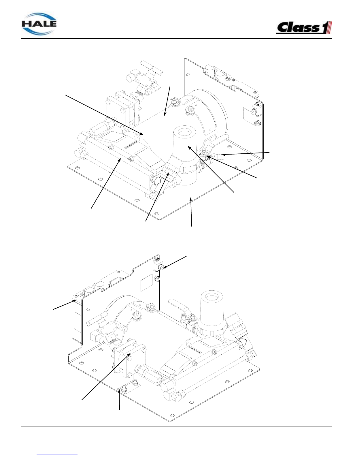
FoamLogix, Model 2.1A and 1.7AHP Class “A”
Electronic Foam Proportioning Systems
79
Figure 45: Foam Pump Assembly
1A
1
3
2
1D
1B
1C
6
7
8 4 5
Page 82
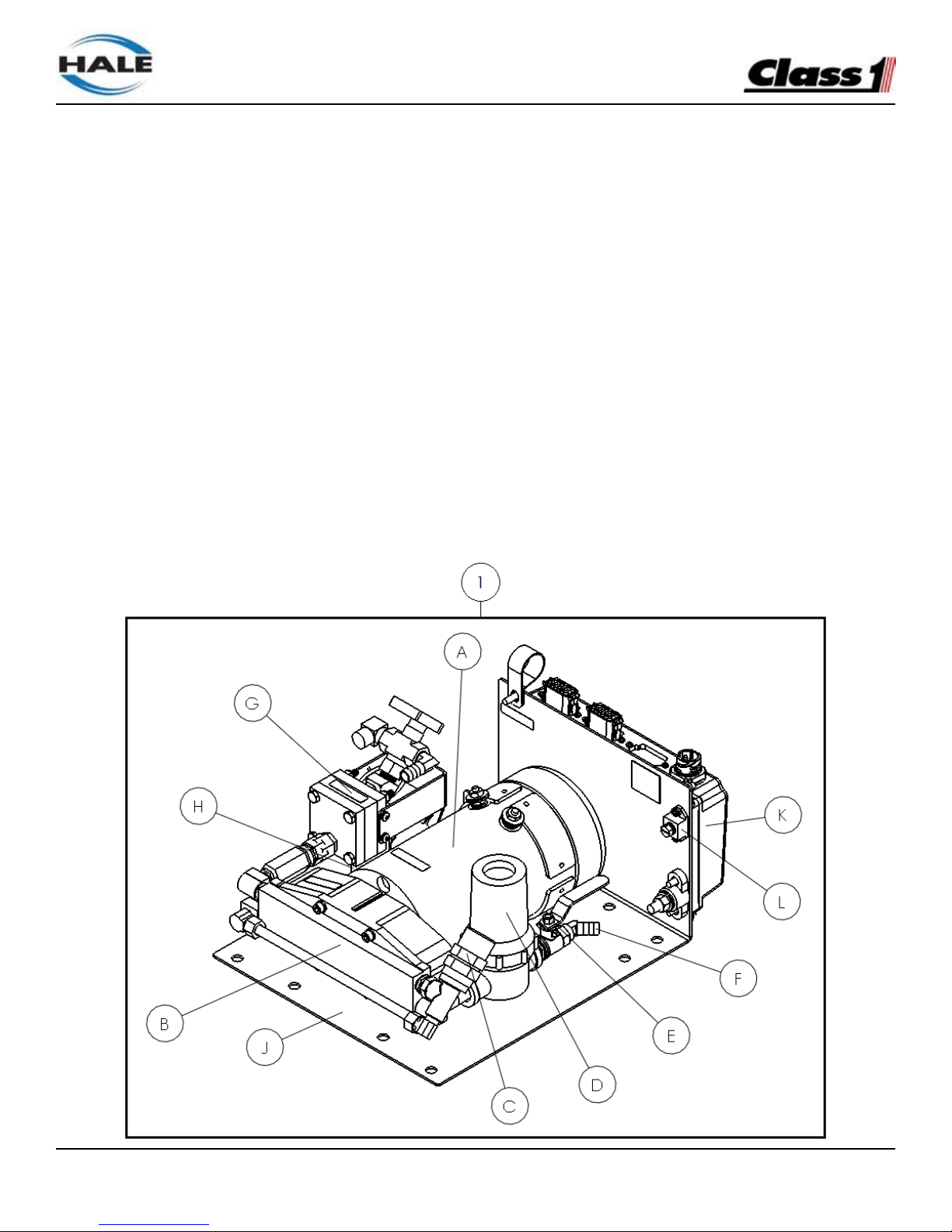
FoamLogix, Model 2.1A and 1.7AHP Class “A”
Electronic Foam Proportioning Systems
80
FOAM PUMP ASSEMBLY – 1.7AHP AND 2.1A
Item Part number Qty Description
1. 114034 1 Motor/Pump Assembly - 2.1A - 12 Volt
114035 1 Motor/Pump Assembly - 2.1A - 24 Volt
119274 1 Motor/Pump Assembly - 1.7AHP - 12 Volt
119275 1 Motor/Pump Assembly - 1.7AHP - 24 Volt
A. 110521 1 Motor 1/2 HP - 2.1A/1.7AHP - 12 Volt
110393 1 Motor 1/2 HP - 2.1A/1.7AHP - 24 Volt
B.
110522 1 Pump Assembly (without motor) - 2.1A
119345 1 Pump Assembly (without motor) - 1.7AHP
C.
538-1750-01-0 1 Relief Valve - 2.1A - 250 PSI
119346 1 Relief Valve - 1.7AHP - 400 PSI
D. 510-0200-02-0 1 Strainer Assembly
E. 119266 1 Ball Valve 3/8” MNPT x FNPT with Handle
F. 082-0328-02-0 1 Elbow 45° 3/8” MNPT x Hose Barb
G. 115497 1 Flowmeter Assembly (see next page for parts list)
H. 019-3770-00-0 1 Flowmeter Mounting Bracket
J. 019-02275 1 Mounting Base
K. 610-00044 1 Motor Controller
L. 122609 1 Diode 45V 240A
Page 83
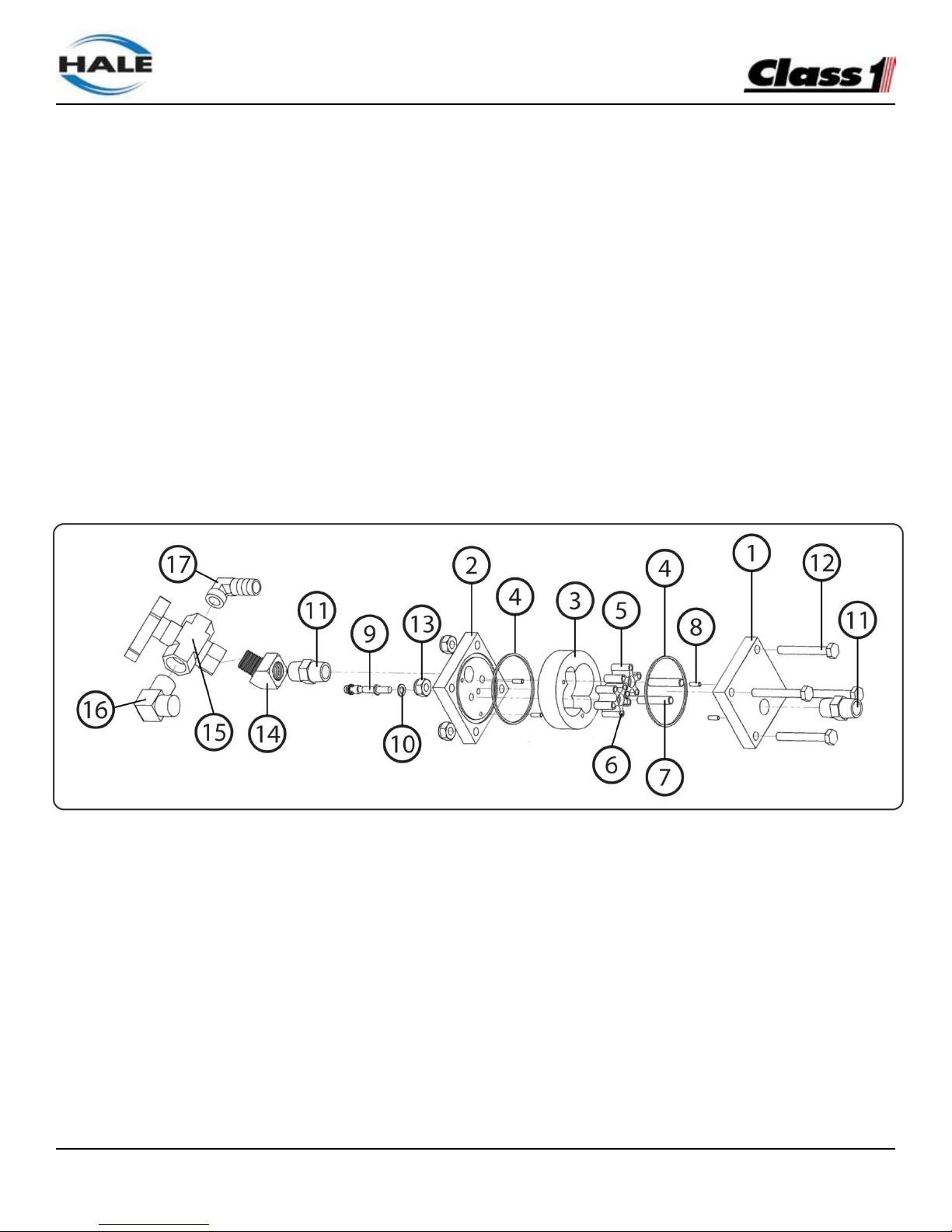
FoamLogix, Model 2.1A and 1.7AHP Class “A”
Electronic Foam Proportioning Systems
81
FLOW METER ASSEMBLY – 1.7AHP AND 2.1A (115497)
Item Part number Qty Description
1. 044-1920-01-0 1 Flowmeter Right Cover
2. 044-1920-00-0 1 Flowmeter Left Cover
3. 062-0910-00-0 1 Flowmeter Housing
4. 040-0340-00-0 2 O-ring 2-034 Buna-N 70 Durometer
5. 016-1010-00-0 2 Flowmeter Rotor
6. 064-6390-00-0 10 Sensor Target for Flowmeter Rotor
7. 064-6680-00-0 2 Dowel Pin Ø0.25” x 1.25” SST
8. 064-6260-01-0 4 Dowel Pin Ø0.13” x 0.38” SST
9. 200-2483-00-0 1 Speed Sensor
10. 097-1971-00-0 1 Sealing Washer #10
11. 082-0364-02-0 2 Hex Adapter 2X 3/8” MNPT
12. 018-1220-12-0 4 Hex Head Bolt 1/4-20 x 2.00” SST
13. 110-1206-02-0 4 Nut Nylock 1/4-20
14. 116964 1 Street Elbow 45° 3/8” NPT
15. 038-2220-00-0 1 Ball Valve 3/8” FNPT 3-way
16. 082-0317-02-0 1 Elbow 90o 3/8” MNPT x 1/2” Tube
17. 082-0327-02-0 1 Elbow 90o 3/8” MNPT x 1/2” Hose Barb
Speed sensor replacement kit – part number 119348 includes:
Item Part number Qty Description
9. 200-2483-00-0 1 Speed Sensor
4. 040-0340-00-0 2 O-ring 2-034 Buna-N 70 Durometer
10. 097-1971-00-0 1 Sealing Washer #10
Page 84

FoamLogix, Model 2.1A and 1.7AHP Class “A”
Electronic Foam Proportioning Systems
82
Figure 46: Foam Flow Meter Assembly
FLOW SENSOR COMPONENTS
1. 102714 ................................................... Paddlewheel Flow Sensor
2. 4842010.................................................. Saddle Clamp 2” with Flowmeter Port
4843010.................................................. Saddle Clamp 2.5” with Flowmeter Port
4844010.................................................. Saddle Clamp 3” with Flowmeter Port
4846010.................................................. Saddle Clamp 4” with Flowmeter Port
4845010.................................................. Saddle Clamp 5” with Flowmeter Port
3. SFM ........................................................ Weld Fitting for Paddlewheel Flow Sensor - Stainless Steel
309010.................................................... Weld Fitting for Paddlewheel Flow Sensor - Aluminum
309020.................................................... Weld Fitting for Paddlewheel Flow Sensor - Steel
4. 113438-A................................................. FoamLogix Control Head Harness - 10’ x 14”
113439-B ................................................ FoamLogix Control Head Harness - 15’ x 19’
5. 108995.................................................... Dual Check Valve Manifold Assembly - 3.0”
108966.................................................... Single Check Valve Manifold Assembly - 3.0”
112074 .................................................... Single Check Valve Manifold Assembly - 2.0”
6. H513-0270-040-D ................................... Power Wire Harness
7. 113434-B ................................................ FoamLogix Distribution Box Harness - Single Tank (Included in
base system - 115498)
8. 513-0320-23-0 ........................................ Tank Select Plug (included in 113434-B Harness)
Page 85
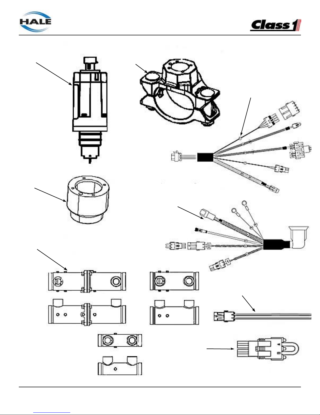
FoamLogix, Model 2.1A and 1.7AHP Class “A”
Electronic Foam Proportioning Systems
83
Figure 47: Flow Sensor Components
1
2
4
3
7
5
Dual Check Valve Manifold
Single Check Valve Manifold
6
8
Page 86
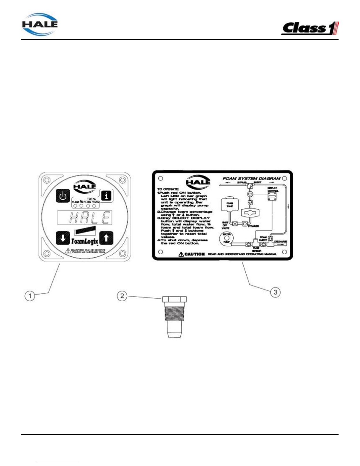
FoamLogix, Model 2.1A and 1.7AHP Class “A”
Electronic Foam Proportioning Systems
84
Additional Foam Logix Components
1.
111530
FoamLogix Control Head
2.
038-1790-00-0
Injector Check Valve
3.
101-1630-70-0
FoamLogix Placard
4.
200-2110-02-0
Side Mount Low Level Tank Sensor
5.
200-2110-04-0
Bottom Mount Low Level Tank Sensor
6.
200-2110-06-0
Top Mount Low Level Tank Sensor
7.
513-0330-01-0
Remote Control Switch Assembly
8.
513-0680-00-0
Remote Control Cable - 16’ (4.88m)
Figure 48: Additional FoamLogix Components
Page 87
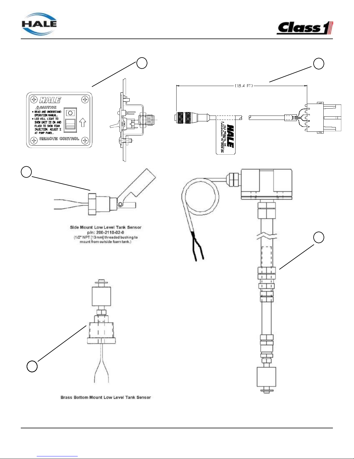
FoamLogix, Model 2.1A and 1.7AHP Class “A”
Electronic Foam Proportioning Systems
85
ADDITIONAL FOAMLOGIX COMPONENTS
Figure 49 Additional FoamLogix Components
7
8
(4.88m)
4
6
5
P/N 200-2100-04-0
(1” NPT (13 mm) threaded bushing to mount from
outside foam tank.)
Top Mount Low Level Tank Sensor
P/N 200-2110-06-0
(Extends from 2-1/2’ to 5’ (0.8 to 1.5 meters) - may
be cut shorter if required.)
Page 88
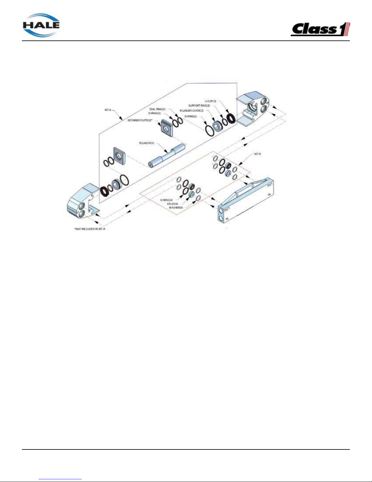
FoamLogix, Model 2.1A and 1.7AHP Class “A”
Electronic Foam Proportioning Systems
86
FoamLogix Pump Repair Kit
Item # Part Number Qty. Description
Kit A...........117495 ..................... 1 ............ Plunger and Seals
Kit B 117496 ..................... 1 ............ Valve and Seals
Kit C .......... 117497..................... 1 ............ Cam Bearing
Page 89
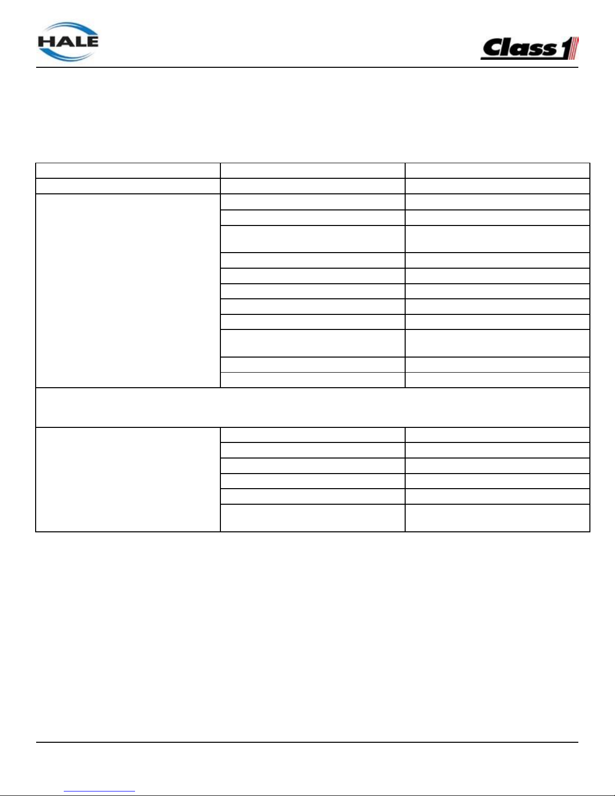
FoamLogix, Model 2.1A and 1.7AHP Class “A”
Electronic Foam Proportioning Systems
87
Appendix A Hale Foam Concentrate Compatibility
The following foam concentrates are approved for use in Hale Foam Proportioning Systems.
The Class A foam concentrates are approved for use in all Hale Foam Proportioning systems (Hale FoamLogix 5.0,
3.3, 2.1A and 1.7AHP and Hale V Series.
TYPE OF FOAM CONCENTRATE
MANUFACTURER
NAME
CLASS A fOAM
US Forestry Service Approved
- Reference *&**
Ansul
Silvex Class A Foam Concentrate
Kidde fire Fighting/Angus Fire
Forexpan S (0.1% - 1.0%)
Kidde fire Fighting/Angus Fire
Hi Combat Class A (lst Defense Class A
cold Water Foam
Kidde fire Fighting/Angus Fire
Knock-Down
Monsanto
PhosCheck WD881
Chemonics
Fire-Trol Fire Foam 103
Chemonics
Fire-Trol Fire Foam 104
3M
Light Water FT-1150
Chemguard
First Class - Class A foam P/N S100307
ABC Macintosh Agent
Bio-For N
Enchem Products Ltd
Enchem 207
* For use in FoamLogix® models 5.0, 3.3, 2.1A , 1.7AHP and Hale V Series
** USFS approved foams have been tested for corrosion and biodegradability toxicity by the US Forest Service in addition
to the Hale testing described on the following page.
Non U.S. forestry Service Approved
- Reference *
Chem Guard
Class A Plus
Unifoam Co. Ltd.
UniA 1%
3M
Light Water SFFF
Kidde Fire Fighting/National Foam
Responder
Kidde Fire Fighting/Angus fire
FirePower Class A
3M-Australia
Fire Brake Bush Fire Fighting Foam
P/N 0295337
Table 50: Hale Foam Concentrate Compatibility
Page 90

FoamLogix, Model 2.1A and 1.7AHP Class “A”
Electronic Foam Proportioning Systems
88
Reference
The preceding foam concentrates have been tested by Hale Products in a Hale FoamLogix® system to
ensure compatibility with Hale FoamLogix® models 2.1A, 1.7AHP, 3.3 and 5.0 Foam Proportioning Systems.
These Chemicals were ran for several hundred hours over several months under nominal conditions to
make sure they do not harm the Foam System. This list is solely intended to assist the end user in
selection of foam concentrate(s) compatible with a Hale FoamLogix® Model 5.0 and 3.3 and is not a
determination of the fire fighting effectiveness of one product over another.
Always consult with NFPA standards, U.L. Listings, Federal, State, and local regulations, and requirements
pertaining to application and environmental regulations before selecting a foam concentrate. Some of the foam
chemicals listed may require special hardware considerations. (Refer to FoamLogix® user manual
for additional information).
Many Fire Fighting Foam Chemical Manufacturers have specific instructions on handling and use of their products including, but not limited to, shelf life, tank life, temperature limits, and intervals between use. Always
follow Manufacturers instructions for use.
This Appendix applies to Hale Foamlogix® foam pumps built after April 17, 1997. For Hale
FoamMaster foam pumps built prior April 17, 1997 refer to Bulletin 650, Rev 2.
If a particular foam concentrate you wish to use does not appear on this list, please contact your Hale
representative for information concerning compatibility with Hale FoamLogix® Foam Proportioning System.
As further testing is completed, Hale Products Inc. updates this list and expands capabilities and features to
keep the Hale FoamLogix® the best system available for all the fires you fight.
Page 91
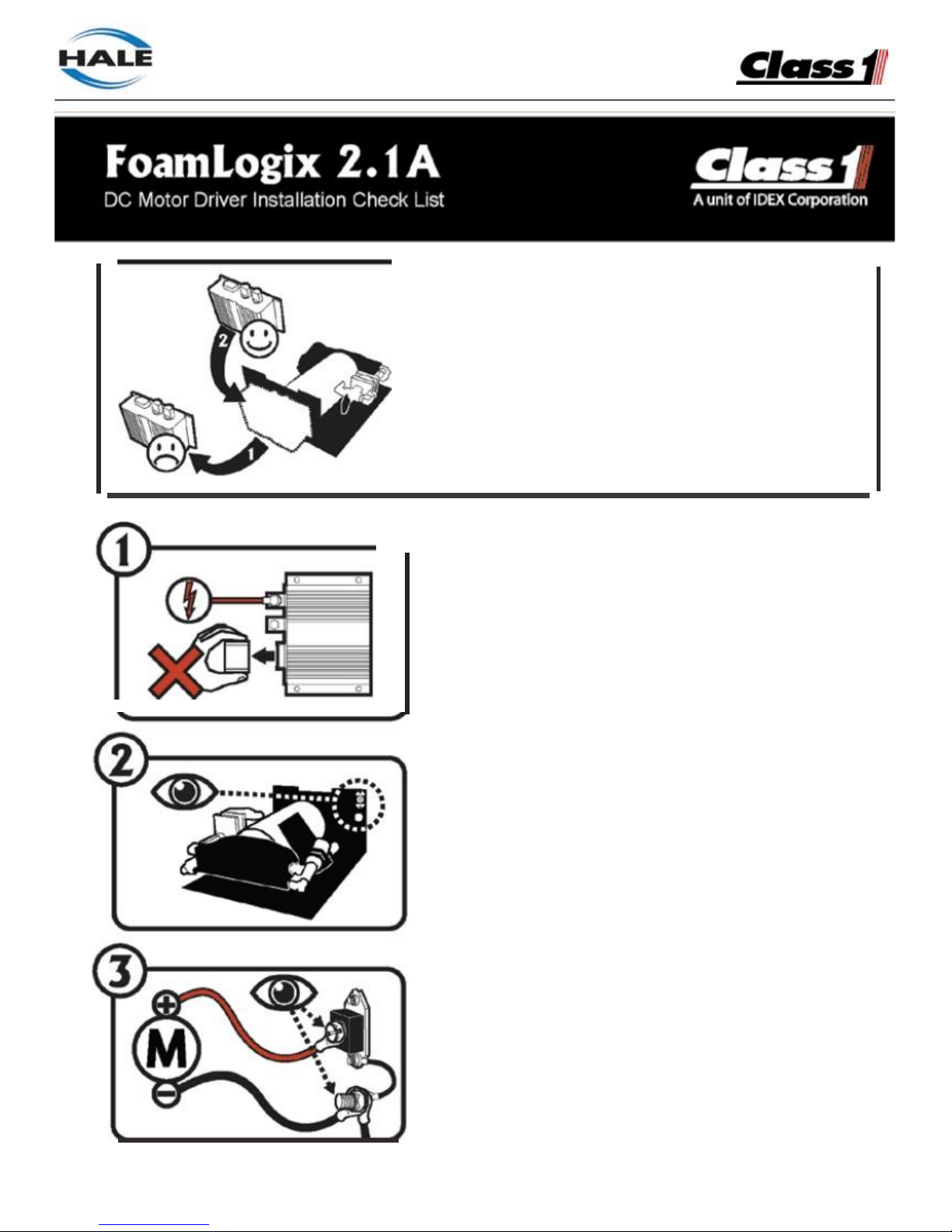
FoamLogix, Model 2.1A and 1.7AHP Class "A•
Electronic Foam Proportioning Systems
89
Please perform the following steps to verify the
Foam ogix system integrity after replacing the
DC Motor Driver.
Realice por favor los pasos siguientes para verifkar la
integridad de sistema de Foamlogix despues de
substituirel DC Motor Driver.
Never disconnect whenpower is applied.
Nunca desconecte cuando la energfa es aplicada.
Find the loca tion of the suppression diode and the
main ground.
Encuentre la localizaci6ndel diodo dela supresi6n
y
del perno de tierra principal.
Verify the motor is connected to the diode and main
ground.
Verifica el motor este conectado conel diodo
y
la tierra principal.
Page 92
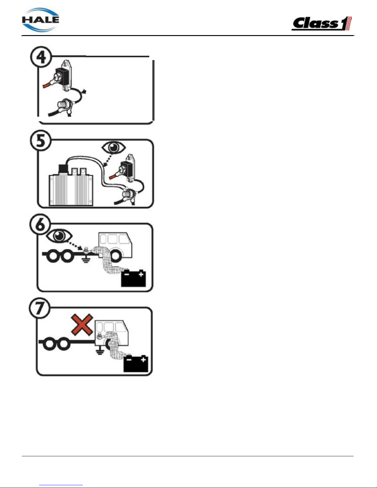
FoamLogix, Model 2.1A and 1.7AHP Class "A'
Electronic Foam Proportioning Systems
90
•
••
.®
••
•
•••
Verify the base of the diode is connected to the main
ground.
Verifica la base del diodo este conectada con la
tierra principal.
Verify two groundwires from the DC Motor Driver are
connected to the main ground.
Verifica dos alambres de tierra delconductor del
DC Motor Driver esten conectados con la tierra principal.
Verify the banery negative is connected to the
vehicle chassis.
Verifica la negativa de la baterfa este conectada
con el chasis del vehfculo.
Do not use the vehicle body as a grounding point.
No utillce elcuerpo del vehfculo como punto que
pone a tierra.
Page 93
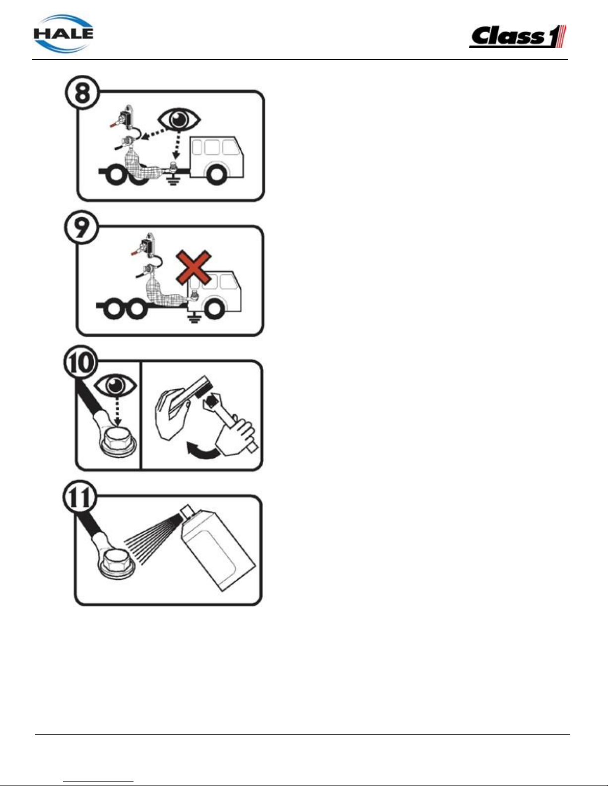
FoamLogix, Model 2.1A and 1.7AHP Class "A'
Electronic Foam Proportioning Systems
92
HALE
Verify the main ground is connected to the vehicle
chassis ground.
Verifica
la
tierra principal este conectada con la
tierra delchasis delvehiculo.
Do not use the vehicle body as a grounding point.
No utilice elcuerpo del vehfculo come punto que
pone a tierra.
Verify that all electrical connections are tightened and
do not have corrosion. Clean and tighten as necessa ry.
Verifica todas las conex iones electricas esten apretadas
y
no tenga corrosion.Limpie y apriete cuanto sea
necesario.
Recommended: Spray all electrical ground and power
connections with battery terminal protectant.
Recomendado: Rode todas las conexiones electricas
de la tierra y de energia con el terminalde la bateria
protectant.
Page 94
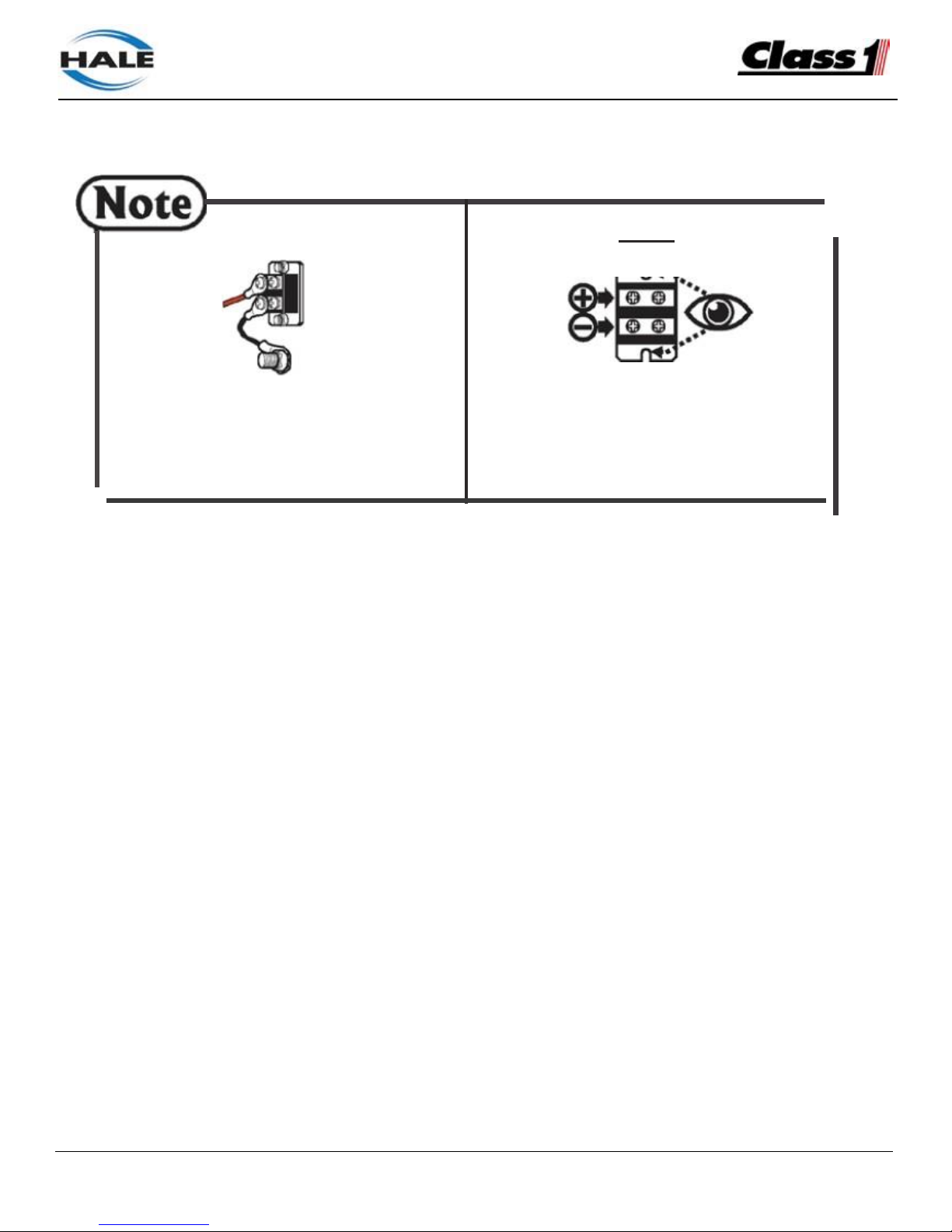
FoamLogix, Model 2.1A and 1.7AHP Class "A'
Electronic Foam Proportioning Systems
92
•
The diode may
be
similar to the one shown
above.
El diode puede ser similar a elque esta
demostrado arriba.
Verify the positive connection is toward the
mounting hole.
Verifica la conexi6n positiva est hacia el
agujero de montaje.
Page 95
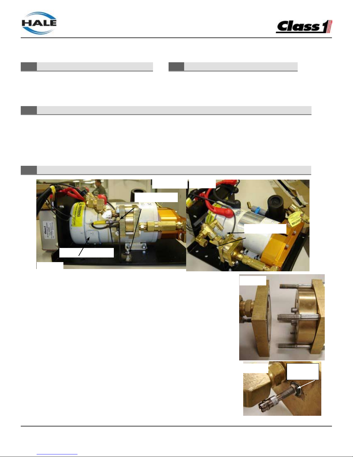
FoamLogix, Model 2.1A and 1.7AHP Class “A”
Electronic Foam Proportioning Systems
93
Foam Flow Sensor Replacement Instructions
- Sealing Washer (097-1971-00-0) - 5/16” wrench
- 119376 - Product/Service Bulletin 0017
• Shut off foam tank supply valve.
• Open bypass valve to drain foam lines and use suitable containers to collect residual foam concentrate.
• Protect eyes and skin from foam concentrate per manufacturer’s Material Safety Data Sheet or MSDS.
1. Carefully disconnect the wire harness from the old foam flow sensor.
• Connect the NEW foam flow sensor to the wire harness.
• Apply system power and verify sensor diagnostic LED is off.
• Touch end of sensor to brass housing → LED should light.
• Disconnect the wire harness from the new sensor.
• Remove system power from the FoamLogix system.
• (This test verifies that the new sensor is operating correctly.)
2. Disconnect both hoses from the 3-way bypass valve.
3. Remove the four (4) nuts on the brass flowmeter assembly with the two 7/16”
wrenches.
4. Remove the two (2) nuts on the bracket bottom with the 7/16” wrench.
5. Remove the sensor side cover of the flowmeter assembly.
• Inspect o-ring inside the cover for damage or cuts.
6. With the 5/16” wrench, loosen the small retaining nut on the foam flow sensor, and
unscrew the sensor by hand.
• Depending on the return instructions provided by the dealer or manufacturer, it may
be necessary to return the old sensor. If not, then the old sensor, nut, and seal washer
can be discarded.
7. The foam flow sensor packaging includes two (2) nuts and two (2) lock washers. Only
one nut is required for the remaining steps.
STEPS 3-4
STEP 2
Remove six nuts
Remove hoses
Remove wire harness
STEP 1
4
REPLACEMENT INSTRUCTIONS
3
SAFETY INFORMATION
• Remove system power from the FoamLogix system and relieve any trapped pressure.
2
REQUIRED TOOLS:
- 7/16” wrench (2X)
1
REPAIR KIT 119348 INCLUDES:
- Foam Flow Sensor (200-2481-00-0)
Sensor nut
& washer
STEP 5
STEP 6
Page 96
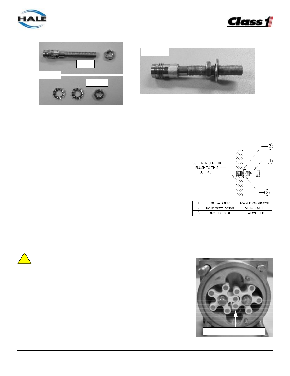
FoamLogix, Model 2.1A and 1.7AHP Class “A”
Electronic Foam Proportioning Systems
94
8. Thread the new foam flow sensor nut onto the sensor about 1/2” (12mm).
9. Thread (do NOT push) the new seal washer onto the foam flow sensor about 1/2” (12mm).
• This seal washer should be silver in color, with a black, rubber seal on the inner diameter.
10. Thread the new foam flow sensor into the brass cover by hand, so that the sensor tip is flush with the inside face of the
cover.
• DO NOT USE LOCTITE OR THREAD SEALANT ON THE
FOAM FLOW SENSOR.
• Use a straight edge or flat object to verify the flush position.
• TIP – When installing the foam flow sensor, it may be easier to lay
the brass cover on a flat surface (carefully remove o-ring), and check
for flush position after the nut is secure.
11. While holding the new foam flow sensor, lightly tighten the nut with
the 5/16” wrench to set the seal washer on the outer face of the brass
cover.
12. Verify that the sensor tip is flush with the inner surface and torque the
jam nut to a maximum 10.0 in-lb (1.1 N-m).
• Do not bend or over-tighten the sensor.
• Use a fine stone to lightly remove any flashing that might stick out after tightening the sensor nut.
13. Remove and inspect the two plastic rotors inside the flowmeter assembly for cracks, burrs, etc.
14. Inspect the inner housing for debris, metal shavings, etc. and remove as necessary.
15. Reinstall both rotors, making sure that each spins freely without binding.
•When installed, the flush end of the metal targets in the rotors must face out,
STEP 15
!
toward the foam flow sensor.
16. Reinstall the o-ring (if necessary) and reattach the brass cover and the bracket
with the six (6) nuts.
• Tighten all nuts securely and torque to a maximum 6.5 ft-lb (8.5 N-m). Use a
criss-cross torque pattern on the four brass housing nuts and bolts.
17. Reattach foam lines and foam flow sensor harness.
18. Apply system power to the FoamLogix system and recalibrate the system per the
user manual instructions.
STEPS 8-9
Keep
Discard
STEP 7
Rotor targets must face sensor
Page 97

Express Warranty
See website for product specific warranty details.
HALE PRODUCTS, INC / CLASS 1
607 NW 27th Avenue ● Ocala, FL 34475 U.S.A. Telephone: 352-629-5020
FAX: 800-533-3569
GODIVA LTD.
Charles Street ● Warwick, England CV34 5LR Phone: 44-1-926-623600
IDEX DINGLEE TECHNOLOGY (Tianjin) Co. Ltd.
No.9, 2nd Haitai Fazhan Road Huayuan Industrial Development Area (outside of ring road)
Tianjin High-Tech Industrial Park Tianjin China
Telephone: 011-86-22-8568-9800
FAX: 011-862285689808
 Loading...