

ESP Primer System
(Includes: SPV and PVG Valves)
Installation, Operation and
Service Maintenance Manual
Hale Products Inc. ◆ A Unit of IDEX Corporation
700 Spring Mill Avenue
Telephone: 610-825-6300
Web......www.haleproducts.com
◆ Conshohocken, PA 19428 U.S.A.
◆ FAX: 610-825-6440
Manual p/n: 029-0810-01-0
NOTICE !
Hale Products, Inc. cannot assume responsibility for product failure resulting from
improper maintenance or operation. Hale is responsible only to the limits stated in
the product warranty. Product specifications contained in this manual are subject
to change without notice.
All Hale products are quality components -- ruggedly designed, accurately
machined, precision inspected, carefully assembled and thoroughly tested. In
order to maintain the high quality of your unit, and to keep it in a ready condition, it
is important to follow the instructions on care and operation. Proper use and good
preventive maintenance will lengthen the life of your unit.
ALWAYS INCLUDE THE UNIT SERIAL NUMBER
IN YOUR CORRESPONDENCE.
ECN No REV CHANGE FROM BY DATE APVD
0499 A INITIAL RELEASE LwH 12/23/2006 MAL
HALE PRODUCTS, INC.
A Unit of IDEX Corporation
Conshohocken, PA 19428 USA
Manual p/n: 029-0810-01-0, Rev. -A
Printed in U.S.A.
WRITTEN BY LwH ISSUE DATE COPYRIGHT ©
CHECKED BY PW 01/05/2007
NOT TO BE REPRODUCED OR USED TO
MAKE OTHER DRAWINGS OR MACHINERY.
© Hale Products, Inc. 2007
All Rights Reserved

Table of Contents ❑
Contents Page
ESP Primer Installation, Operation and Service Guide
1 Safety Precautions................................................................................................... 7
1.1 Definitions...........................................................................................................................7
1.2 Guidelines...........................................................................................................................8
2 Introduction........................................................................................................... 11
2.1 ESP Primer Pump............................................................................................................. 11
Figure 2-1: Rotary Vane ESP Priming Pump.........................................................................11
2.2 SPV Priming Valve ...........................................................................................................12
Figure 2-2: SPV Overview .....................................................................................................12
Overview...........................................................................................................................................12
Configuration Options .......................................................................................................................13
Retrofit Kit Option.......................................................................................................................13
Universal Mount Installation Kit Option ......................................................................................13
Midship Pump Mounted Option ..................................................................................................13
Primer Mounted on Midship Pump .............................................................................................14
2.3 PVG Priming Valve...........................................................................................................14
Figure 2-3: PVG Priming Valves............................................................................................14
2.4 Lubricated ESP Primer System....................................................................................... 14
Figure 2-4: Typical ESP Lubricated System ..........................................................................15
Chart 2-5: Typical Freeze-Up Protection..............................................................................16
3 System Installation................................................................................................ 17
3.1 Primer Pump ..................................................................................................................... 17
Installation Notes ..............................................................................................................................17
Figure 3-1: Solenoid Connector Arrangement .......................................................................18
Optional Bracket Installation .............................................................................................................19
ESP System Plate Drawings ............................................................................................................ 19
3.2 Valve Installation, SPV or PVG........................................................................................ 19
Figure 3-2: Typical Hale SPV Typical System Layout ...........................................................20
SPV Placard and Pushbutton ...........................................................................................................20
Figure 3-3: SPV Pushbutton Placard Overview.....................................................................21
ESP Primer System In struction Guide
p/n: 029-0810-01-0
3

❑ Table of Contents
Contents - continued Page
3.2 Valve Installation, SPV or PVG - continued
SPV Retrofit Installation, Midship ..................................................................................................... 22
Figure 3-4: Typical SPV / Midship Pump Installation.............................................................22
Figure 3-5: SPV Retrofit Panel Placard Spacer Layout ......................................................... 23
SPV Retrofit Installation, Universal Mount........................................................................................ 25
Figure 3-6: Typical SPV / Universal Adapter Pump Installation.............................................25
Figure 3-7: Universal Mount Adapter Dimensions................................................................. 26
Figure 3-8: Universal Mount Adapter Positions ..................................................................... 26
PVG Installation................................................................................................................................ 27
Figure 3-9: PVG Panel Placard and Valve Plumbing Layout................................................. 28
3.3 Lubricated Primer Installation ...................................................................................... 29
Installation ........................................................................................................................................ 29
Figure 3-10: Typical ESP Lubricated Primer Layout................................................................ 30
Figure 3-11: Pump Fittings ...................................................................................................... 31
4 Primer Operation .................................................................................................. 33
4.1 Priming the Pump ............................................................................................................ 33
5 System Maintenance.............................................................................................. 35
5.1 General Maintenance....................................................................................................... 35
Weekly..............................................................................................................................................35
Priming System Test.................................................................................................................. 35
Monthly............................................................................................................................................. 36
Priming System Test, Dry Vacuum Test.................................................................................... 36
Figure 5-1: PVG Priming Valve Handle ................................................................................. 36
Annually............................................................................................................................................37
Clean ESP Priming Pump..........................................................................................................37
Figure 5-2: Primer Pump Parts Overview .............................................................................. 37
5.2 SPV Valve Repair .............................................................................................................39
Figure 5-3: Hale SPV Parts Overview ...................................................................................40
5.3 PVG Valve Repair ............................................................................................................42
Figure 5-4: Hale PVG Parts Overview...................................................................................42
Figure 5-5: PVG Valve Parts Breakdown ..............................................................................43
Reassembly Hints.............................................................................................................................44
4
ESP Primer System Instruction Guide
p/n: 029-0810-01-0

Table of Contents ❑
Contents - continued Page
5.4 Lubricant Specifications..................................................................................................45
Grease, for O-ring Seals...................................................................................................................45
Loctite Sealant..................................................................................................................................45
Recommended Cleaners ..................................................................................................................45
Lubricants .........................................................................................................................................45
6 Troubleshooting .................................................................................................... 47
Figure 6-1: Troubleshooting Chart......................................................................................... 47
Pump Loses Prime or Will Not Prime...................................................................................47
Primer Solenoid - 12VDC and 24VDC .................................................................................49
Switch is dead - no click is heard.........................................................................................49
Switch chatters, pops or clicks, but the motor does not work. ...........................................49
Switch stays ON (sticks) - motor keeps running. .................................................................50
Figure 6-2: 12VDC Solenoid Arrangement Troubleshooting .................................................50
Figure 6-3: 24VDC Solenoid Arrangement Troubleshooting .................................................50
Express Warranty ................................................................................................. 51
Hale Products, Inc. ..........................................................................................................................52
7 Drawing Package................................................................................................... 53
Hale ESP-12 Priming System .............................................................................................................821A
Hale ESP-24 Priming System .............................................................................................................938A
Hale PVG Valve ..................................................................................................................................480A
Hale SPV Valve, Universal Mount.......................................................................................................828A
Hale SPV Valve, Pump Mount ............................................................................................................819A
ESP Primer System Instruction Guide
p/n: 029-0810-01-0
5

❑ Table of Contents
Contents - continued Page
Notes
_______________________________________________________________________
_______________________________________________________________________
_______________________________________________________________________
_______________________________________________________________________
_______________________________________________________________________
_______________________________________________________________________
_______________________________________________________________________
_______________________________________________________________________
_______________________________________________________________________
_______________________________________________________________________
_______________________________________________________________________
_______________________________________________________________________
_______________________________________________________________________
_______________________________________________________________________
_______________________________________________________________________
_______________________________________________________________________
_______________________________________________________________________
_______________________________________________________________________
_______________________________________________________________________
_______________________________________________________________________
_______________________________________________________________________
_______________________________________________________________________
_______________________________________________________________________
_______________________________________________________________________
_______________________________________________________________________
_______________________________________________________________________
_______________________________________________________________________
_______________________________________________________________________
_______________________________________________________________________
_______________________________________________________________________
_______________________________________________________________________
6
ESP Primer System Instruction Guide
p/n: 029-0810-01-0
1 Safety Precautions
THE HALE ESP PRIMER SYSTEM, WHICH INCLUDES THE SEMI-AUTOMATIC
PRIMING VALVE (SPV) OR THE PVG PRIMER VALVE, IS DESIGNED FOR OPTI-
MUM SAFETY OF ITS OPERATORS. FOR ADDED PROTECTION, PLEASE FOLLOW THE SAFETY GUIDELINES LISTED IN THIS SECTION. ADHERE TO ALL
WARNING, DANGER, CAUTION AND IMPORTANT NOTES FOUND WITHIN THIS
MANUAL.
ALL SUPPLIED DOCUMENTATION MUST BE CAREFULLY READ, UNDERSTOOD
AND ADHERED TO STRICTLY BY ALL INSTALLERS AND OPERATORS BEFORE
ATTEMPTING INSTALLATION OR OPERATION.
WHEN DEVELOPING DEPARTMENTAL APPARATUS OPERATING PROCEDURES,
INCORPORATE THE WARNINGS AND CAUTIONS AS WRITTEN.
Safety ❑
IMPORTANT !
Hale is a registered trademark of Hale Products, Incorporated. All other brand and product
names are the trademarks of their respective holders.
1.1 DEFINITIONS
DANGER - Immediate hazard which WILL result in severe personal injury or
death if the warning is ignored.
WARNING - Hazards or unsafe practices which COULD result in severe personal injury or death if the warning is ignored.
CAUTION - Hazards or unsafe practices which COULD result in minor or moderate personal injury if the warning is ignored.
DANGER !
WARNING !
CAUTION !
ESP Primer System Instruction Guide
p/n: 029-0810-01-0
7
❑ Safety
NOTICE !
NOTICE - Practices which could result in damage to the apparatus or other
property.
1.2 GUIDELINES
NOTICE !
THE PROCEDURES IN THIS MANUAL ARE GENERAL OPERATING PROCEDURES. THEY DO NOT REPLACE THE PROCEDURES, POLICIES OR GUIDELINES ESTABLISHED BY THE AUTHORITY HAVING JURISDICTION, NOR DO
THEY REPLACE THE RECOMMENDATIONS AND PROCEDURES PROVIDED IN
THE APPARATUS MANUFACTURER'S MANUAL.
REFER TO THE PROCEDURES PROVIDED BY THE AUTHORITY HAVING JURISDICTION ON SETTING WHEEL CHOCKS (TO PREVENT ANY MOVEMENT OF THE
APPARATUS), AS WELL AS LAYOUT AND CONNECTION OF HOSES, VALVES
AND DRAIN COCKS.
❑ Use care when removing the primer system, including SPV and PVG valves,
from its packaging to prevent personal injury and/or damage to the
components.
❑ Use all mounting bolt holes provided on the primer to support the assembly.
See the appropriate plate drawing, located at the back of this manual, for
additional installation information.
❑ Installation should be performed by a trained and qualified installer, such as
your authorized service representative. Be sure the installer has sufficient
knowledge, experience and the proper tools before attempting any installation.
❑ The installer is responsible for observing all instructions and safety precau-
tions in his or her daily routine as dictated by regional safety ordinances or
departmental procedures.
CAUTION !
ALL FASTENERS USED HAVE BEEN SELECTED FOR THEIR APPLICATION.
HALE PRODUCTS DOES NOT RECOMMEND REPLACING FASTENERS WITH
ANYTHING OTHER THAN HALE PART NUMBERS PROVIDED. REPLACING WITH
A WEAKER ALTERNATIVE POSES A SERIOUS SAFETY RISK.
ALL FASTENERS MUST BE INSTALLED WITH A LOCKING ANAEROBIC ADHESIVE/SEALANT, SUCH AS LOCTITE
8
®
#246.
ESP Primer System Instruction Guide
p/n: 029-0810-01-0

Safety ❑
CAUTION - continued !
BE SURE TO WEAR SAFETY GLASSES WHEN REMOVING AND/OR INSTALLING
FORCE (PRESS) FITTED PARTS. FAILURE TO COMPLY MAY RESULT IN SERIOUS INJURY.
❑ Parts under spring tension can become projectiles and cause serious injury.
When removing or installing these parts make sure they are restrained and
spring tension is released slowly.
❑ Disconnect or turn OFF the master battery switch prior to servicing the Hale
SPV or PVG electrical components. Make sure there is NO power at the
primer solenoid before starting service procedures.
❑ Any electrical system has the potential to cause sparks during installation,
service or repair. Take care to eliminate explosive or hazardous environments during installation, service or repair.
❑ Before connecting any cord sets or wiring harnesses, inspect the seal
washer in the connector. If the seal washer is missing or damaged, water
can enter the connector causing corrosion. This could resulting in possible
system failure.
❑ DO NOT operate the system at pressures higher than the maximum rated
pressure. Always use the lowest possible relief valve settings to enhance
operator and equipment safety. Also see Section 3 “System Installation” on
page 17 for additional information.
❑ Relieve all system pressure, then drain all water from the system before
installing the primer.
❑ Use only pipe, hose and fittings which are rated at or above the maximum
pressure rating at which the water pump system operates.
❑ Use only pipe, hose and fittings from the priming pump vacuum connection
to the Hale SPV vacuum connection rated for 29 in. Hg. (737 mm) vacuum.
❑ Check all hoses for weak or worn conditions after each use. Ensure that all
connections and fittings are tight and secure.
CAUTION
MAKE SURE THE HALE SPV IS LOCATED HIGHER THAN THE PUMP BODY
ALLOWING WATER TO DRAIN FROM THE VACUUM HOSE.
❑ If there is primer lubricant in the reservoir, it is recommended to operate
lubricated priming systems weekly to cycle the fresh lubricant through the
primer.
ESP Primer System Instruction Guide
p/n: 029-0810-01-0
9

❑ Safety
Holding the primer ON for two (2) or three (3) seconds after a prime from
draft will clean out residue in the primer.
❑ DO NOT run the primer over forty-five (45) seconds. If prime is not achieved
within 45 seconds, stop and look for causes (air leaks or blocked suction
hoses).
❑ Always use caution when handling or disposing of propylene glycol.
❑ DO NOT USE ETHYLENE GLYCOL.
❑ DO NOT allow coolant to discharge to the ground. Review your departmen-
tal and/or local environmental regulations regarding the use of and disposal
of propylene gylcol coolants.
❑ Always follow the manufacturer’s recommended instructions on the label
affixed to the container.
10
ESP Primer System Instruction Guide
p/n: 029-0810-01-0
2Introduction
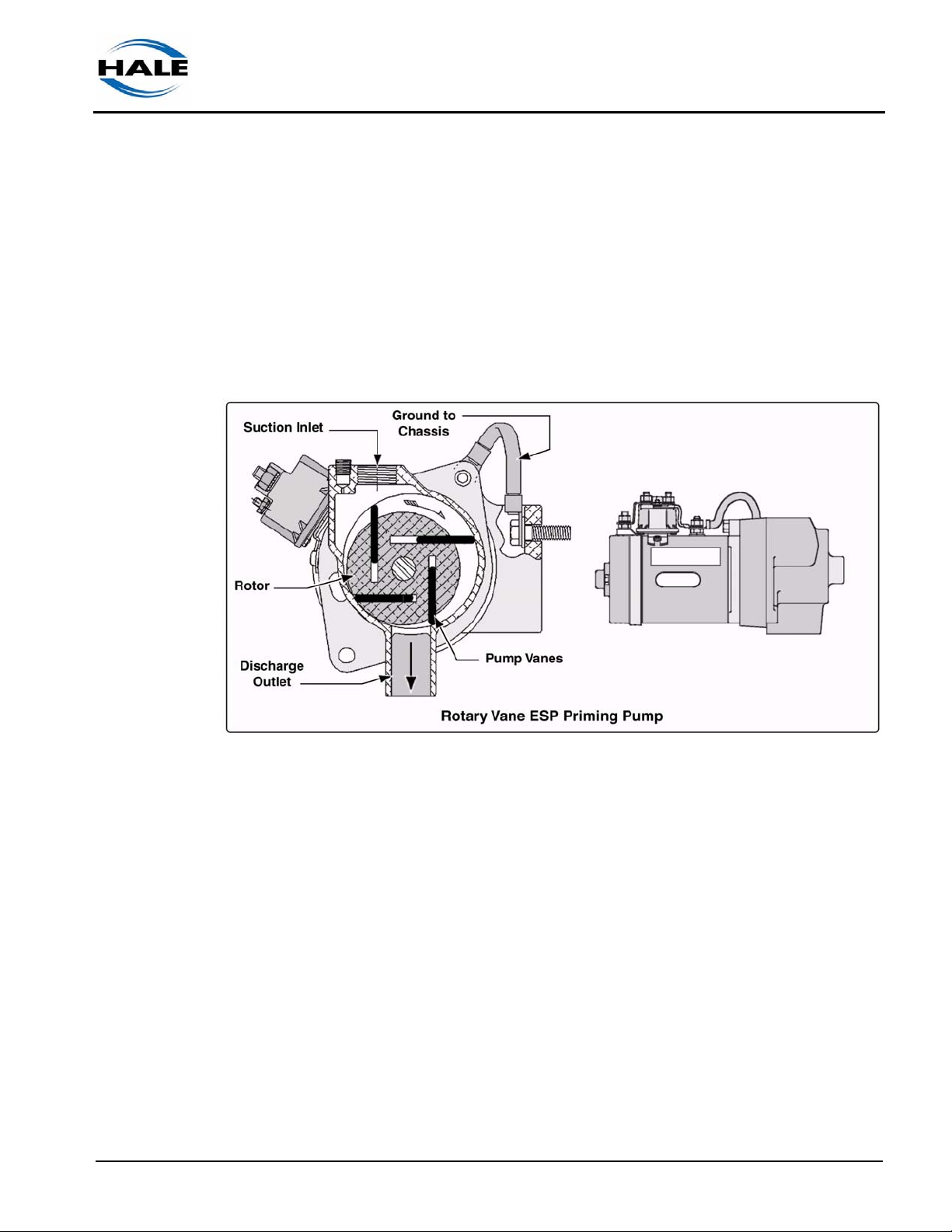
2.1 ESP PRIMER PUMP
Hale recommends and uses Rotary Vane Positive Displacement pumps
(ESP) for priming. Priming pumps are used to evacuate air in the suction
hose and pump. (See Figure 2-1: “Rotary Vane ESP Priming Pump.”)
Introduction ❑
ESP Primer System I nstruction Guide
p/n: 029-0810-01-0
Figure 2-1: Rotary Vane ESP Priming Pump
The Hale ESP series priming pump is an environmentally friendly primer
that does not require a separate lubricant reservoir.
The vanes and pump body are self-lubricating for maintenance free operation. An ESP priming pump also uses a single control to open the priming
valve and start the priming motor.
Note: For an optional “ESP Primer lubricated system,” also see heading “Lubricated ESP Primer System” on page 14.)
Hale priming valves open when the priming pump is operated allowing the
air to escape from the pump. Two priming valves offered:
a. Semi-Automatic Priming Valve (SPV / SPVR) - also see heading “SPV
Priming Valve” on page 12.
b. PVG Priming Valve - also see heading “PVG Priming Valve” on page 14.
11
❑ Introduction
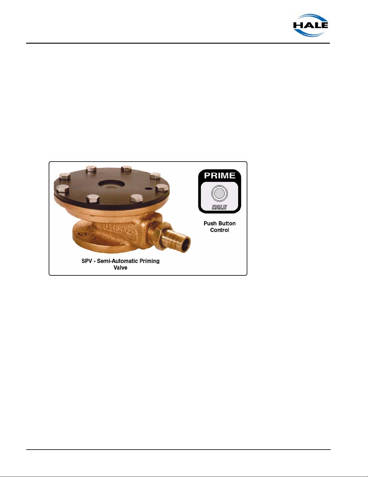
2.2 SPV PRIMING VALVE
The Hale Semi-Automatic Priming Valve (SPV) simplifies the priming opera-
tion of your pump allowing for a faster priming time and longer primer life .
The SPV is a diaphragm-operated valve that opens using the vacuum gen-
erated by the priming pump.
Easily activated by a push button control, the SPV starts the primer motor
creating a vacuum. The vacuum acts on the diaphragm in the valve causing
the port to open allowing vacuum. (See Figure 2-2: “SPV Overview.”)
12
Figure 2-2: SPV Overview
The SPV conforms to NFPA requirements for priming time and hydrostatic
test when bolted to Hale Midship series pumps. Each valve is factory tested
to 26 in. (660 mm) hg. vacuum and 600 PSIG (41 BAR)
Overview
The SPV mounts directly to the priming connection of Hale Midship series
pumps. Additionally, a universal adapter is available to mount the SPV on
Hale Booster and Volute series pumps. The installer must also supply hose
connections from the adapter to the pump priming connection.
When used on a midship fire pump, the valve mounts to the pump body with
two studs and nuts, standard strainer and seal ring.
A short length of 3/4” (19 mm) ID vacuum hose connects the SPV to the
priming pump, eliminating potential leak points in the priming hose.
ESP Primer System Instruction Guide
p/n: 029-0810-01-0

Introduction ❑
The short length of hose also allows for a faster priming time and longer
primer life by reducing the volume that must evacuated.
The priming pump motor is push-button operated, located on the pump
operator panel of the apparatus. There are NO hose connections at the
pump operator panel thus saving valuable space.
Depressing and holding the PRIME push button energizes the priming
pump motor creating a vacuum in the 3/4” (19 mm) ID hose. As sufficient
vacuum is created the diaphragm depresses the spring to OPEN the priming valve, thus creating a vacuum in the main pump body, priming the main
pump. Once primed, as indicated by water discharging to the ground from
the priming pump outlet, the push button is released to STOP the priming
pump. The SPV then CLOSES for normal pump operation.
Configuration Options
The Hale SPV is available from the factory in four (4) different configurations. A description of each follows, beginning on the next page.
Retrofit Kit Option
The retrofit kit contains the components necessary for installing the Hale
SPV on a midship fire pump. The kit contains a Hale SPV Valve assembly,
panel placard and push button switch.
Universal Mount Installation Kit Option
The Universal Mount Installation Kit contains the components necessary for
installing the Hale SPV on a volute or booster type pump. The kit contains a
Hale SPV Valve assembly, universal mounting adapter, panel placard and
push button switch.
Midship Pump Mounted Option
This option mounts the Hale SPV to the priming flange connection on a
“new” midship pump body. Components included with this option and
shipped with the midship pump are the push button switch, panel placard
and Installation Manual.
When completing the apparatus installation of the Hale SPV, the priming
pump must be mounted on the apparatus with the vacuum hose connected
in addition to the push-button switch and panel placard being installed on
the operator panel.
ESP Primer System I nstruction Guide
p/n: 029-0810-01-0
13
❑ Introduction
Primer Mounted on Midship Pump
This option mounts the Hale SPV to the priming flange connection on a
“new” midship pump body with the priming pump mounted to the pump
gearbox. When this option is ordered, the vacuum hose is connected from
the Hale SPV to the priming pump.
Components included with this option and shipped with the midship pump
are the push button switch, panel placard and Installation Manual.
When completing the apparatus installation of the Hale SPV with this option
the push-button switch and panel placard must be installed on the operator
panel.
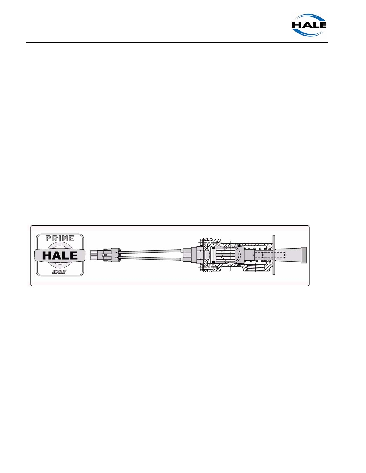
2.3 PVG PRIMING VALVE
The PVG is a combination valve and switch and is mounted on the pump
operator’s panel. (See Figure 2-3: “PVG Priming Valves.”)
Figure 2-3: PVG Priming Valves
Pulling the handle out OPENS the valve and energizes the primer motor.
Pushing the handle in de-energizes the primer motor and CLOSES the
valve.
2.4 LUBRICATED ESP PRIMER SYSTEM
The Hale ESP Priming System has a proven history of reliable fast priming
and high vacuum performance when properly maintained and operated in
accordance with the instructions found in your Pump Installation, Operation
and Service Maintenance Manual and in this guide. Under NORMAL operating conditions (standard climates) our research has found that no lubricant is required.
14
ESP Primer System Instruction Guide
p/n: 029-0810-01-0
Introduction ❑
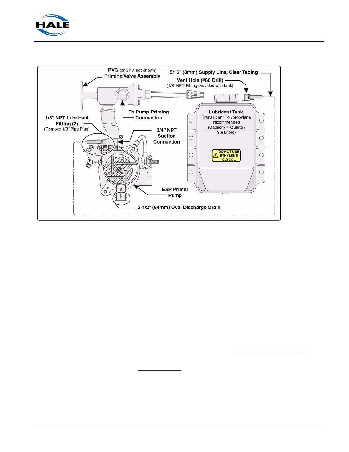
Figure 2-4: Typical ESP Lubricated System
The Hale ESP Priming System can be converted to a “lubricated system” by
installing “separate” lubricant and discharge tanks and using a Propylene
Glycol / water mixture as the lubricant. (See Figure 2-4: “Typical ESP Lubricated System.”)
Propylene Glycol is a less toxic and more environmentally-friendly coolant
and is recommended over Ethylene Glycol based antifreeze.Propylene Glycol (PG) based antifreeze provides comparable system protection to that of
conventional ethylene glycol (EG) based coolants (i.e., freeze, and corrosion protection).
Propylene glycol is readily available in automotive supply stores, under the
following brand names:
❑ Sierra Antifreeze – use a 50 – 50 mix (www.sierraantifreeze.com)
❑ RV & Marine Easy Going Antifreeze, Camco Mfg. – use pure, DO NOT
mix. (www.camco.net)
A 50/50 blend of propylene glycol coolant and water has a freezing point of
-26° F (-32° C) and is applicable under most operating conditions.
ESP Primer System I nstruction Guide
p/n: 029-0810-01-0
If a lower temperature protection is required, it can readily be achieved by
increasing the coolant. (See Chart 2-5: “Typical Freeze-Up Protection,” on
page 16.)
15
❑ Introduction
Coolant Water
50% 50% -26 (-32)
60% 40% -54 (-48)
66% 34% -76 (-60)
Freezing Point
F° (C°)
Chart 2-5: Typical Freeze-Up Protection
IMPORTANT!
IF THERE IS PRIMER LUBRICANT IN THE RESERVOIR, IT IS RECOMMENDED
TO OPERATE LUBRICATED PRIMING SYSTEMS WEEKLY TO CYCLE THE
FRESH LUBRICANT THROUGH THE PRIMER.
HOLDING THE PRIMER ON FOR TWO (2) OR THREE (3) SECONDS AFTER A
PRIME FROM DRAFT WILL CLEAN OUT RESIDUE IN THE PRIMER.
16
ESP Primer System Instruction Guide
p/n: 029-0810-01-0

3 System Installation
ESP Primer Systems are available mounted to Midship pump gearboxes or to the
pump body on new orders.
3.1 PRIMER PUMP
For the Hale 12 volt ESP Primer System installation instructions see drawing “12 Volt ESP System” on page 54. For the 24 volt ESP Primer System
installation instructions see drawing “24 Volt ESP System” on page 54.
Notes: The 12 and 24 volt drawings offer two sheets, one for mechanical installation and one for electrical.
Installation ❑
For the optional Lubricated ESP Primer System installation instructions and
drawings, see heading 3.3 “Lubricated Primer Installation” on page 29.
Installation Notes
❑ Select a mounting location that is rigid, is accessible for maintenance, is
as close as possible to the main pump and with the primer discharge
pointing down (to allow for proper drainage).
Notes:
● Mounting screws and washer are not provided by Hale.
● For competitive brand optional installation, see heading “Optional
Bracket Installation” on page 19. A bracket is available to mount the ESP
primer to a competitive pump. Contact Hale Customer Service for additional information.
❑ Use 1/2” (13 mm) tubing for Hale Booster Pumps.
❑ Use 3/4” (19 mm) tubing for Hale Midship Pumps.
❑ Use 2-1/2” (64 mm) rubber hose for primer discharge.
ESP Primer System I nstruction Guide
p/n: 029-0810-01-0
❑ Suction connection to priming valve is 3/4” NPT.
❑ A shut-off valve, i.e., Hale PVG or SPV Priming Valve, must be located in
the priming line between the primer pump and the main pump.
❑ Ground the priming pump to the truck chassis, using the ground strap
provided.
17
❑ Installation
Attach the ground strap from the truck chassis to the priming pump terminal stud to ensure a ground for the motor. See appropriate drawing,
sheet 2.
The ground strap is appropriately sized for a 12 or 24 volt DC, 300 or 150
amp load.
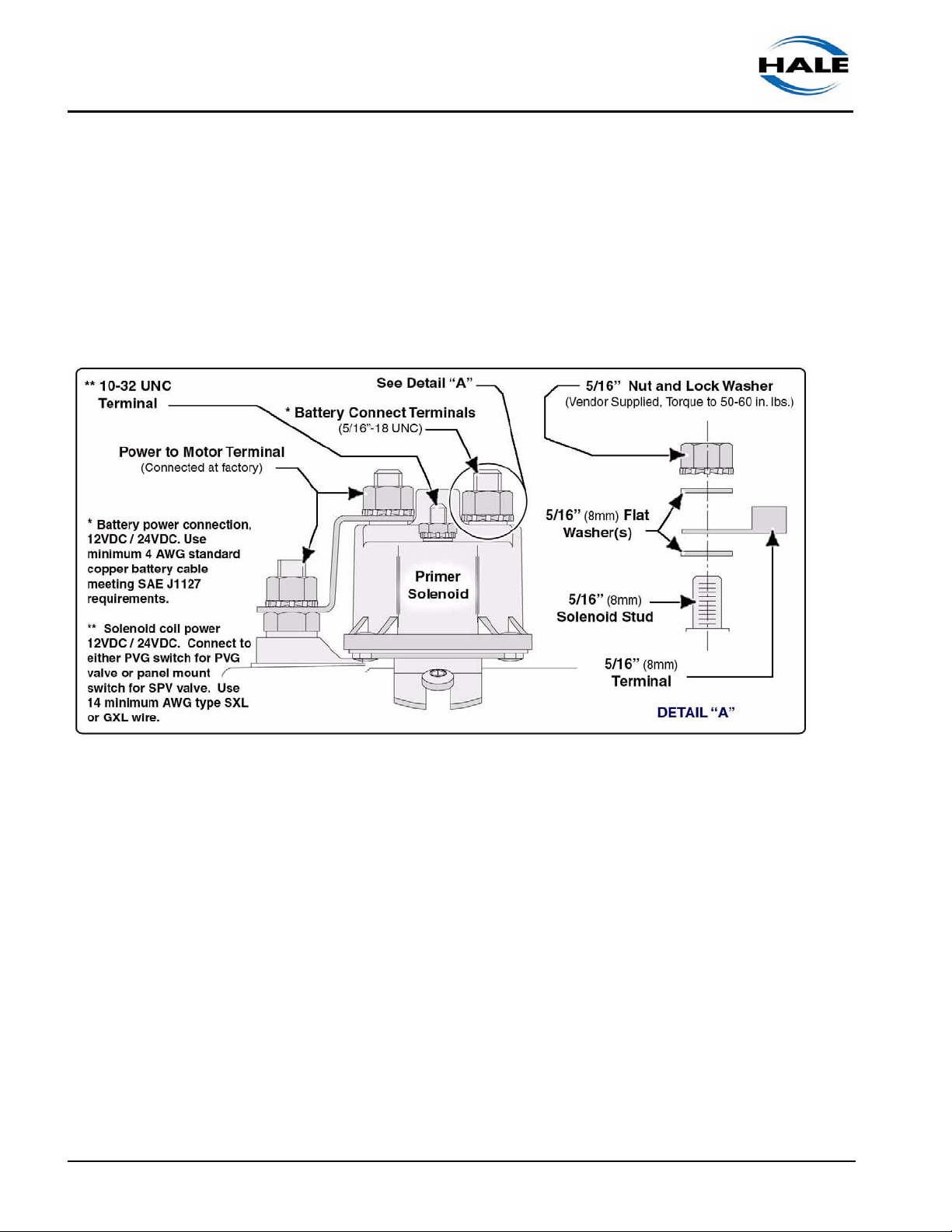
❑ To prevent damage to the solenoid plastic housing, when installing or
removing wire leads, DO NOT apply side loads to the nuts. (See Figure
3-1: “Solenoid Connector Arrangement.”)
18
Figure 3-1: Solenoid Connector Arrangement
❑ When using a terminal lug on the battery connection with a 5/16” (8 MM.)
diameter hole, the lower washer is not needed.
❑ If the hole is larger than 5/16”, washers are required both above and
below the terminal. Torque to 50 - 60 in. lbs. (6 - 7 N-m) maximum.
DO NOT overtighten to avoid stripping the stud from plastic cap.
❑ The solenoid-to-ground terminal, 10-32 UNC, is factory connected and
torqued to 15 - 20 in. lbs. (1.7 - 2 N-m).
DO NOT overtighten to avoid stripping the stud from plastic cap.
❑ For complete electrical installation instructions, see sheet 2 of drawing
“12 Volt ESP System” on page 54 or see sheet 2 of drawing “24 Volt ESP
System” on page 54.
ESP Primer System Instruction Guide
p/n: 029-0810-01-0

Installation ❑
NOTICE !
DO NOT RUN THE PRIMER OVER FORTY-FIVE (45) SECONDS. IF PRIME IS
NOT ACHIEVED WITHIN 45 SECONDS, STOP AND LOOK FOR CAUSES (AIR
LEAKS OR BLOCKED SUCTION HOSES).
Optional Bracket Installation
A mounting bracket is available to install the Hale ESP primer pump to
some competitive pumps. Contact Hale Customer Service for additional
information.
ESP System Plate Drawings
Hale ESP-12 Priming Pump, Mechanical Installation,
Sheet 1 of 2 ........................................................................................821A
Hale ESP-12 Priming Pump, Electrical Installation,
Sheet 2 of 2 ........................................................................................821A
Hale ESP-24 Priming Pump, Mechanical Installation,
Sheet 1 of 2 ........................................................................................938A
Hale ESP-24 Priming Pump, Electrical Installation,
Sheet 2 of 2 ........................................................................................938A
(Click above to view)
3.2 VALVE INSTALLATION, SPV OR PVG
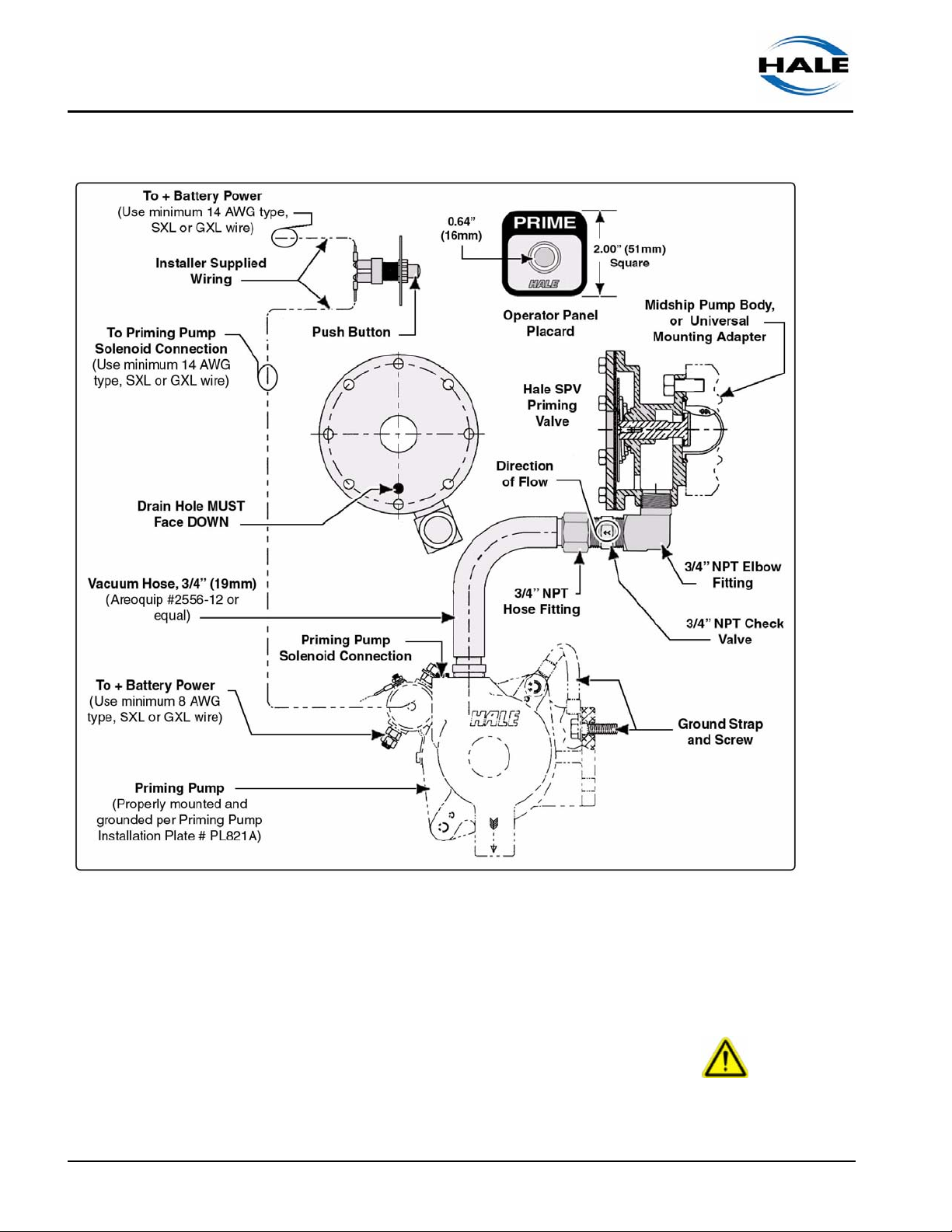
When ordered as an option on a new midship fire pump, the Hale SPV
assembly is already mounted to the pump body with the vacuum hose connected to the priming pump (when the primer is ordered mounted to the
gearbox). All that remains is to install the panel placard and push button on
the pump operator panel and make the electrical connections from the
switch to the battery and priming pump solenoid. (See Figure 3-2: “Typical
Hale SPV Typical System Layout,” on page 20.)
ESP Primer System I nstruction Guide
p/n: 029-0810-01-0
If the midship pump is ordered with the primer shipped loose, it must be
attached to the apparatus and the priming hose must be attached to the
Hale SPV or PVG hose connection (3/4” NPT).
19
❑ Installation
20
Figure 3-2: Typical Hale SPV Typical System Layout
SPV Placard and Pushbutton
WARNING !
DISCONNECT OR TURN OFF THE MASTER BATTERY SWITCH PRIOR TO
SERVICING THE HALE SPV ELECTRICAL COMPONENTS.
ESP Primer System Instruction Guide
p/n: 029-0810-01-0
Installation ❑
WARNING - continued !
MAKE SURE THERE IS NO POWER AT THE PRIMER SOLENOID BEFORE
STARTING SERVICE PROCEDURES. ALSO SEE SECTION 1 “SAFETY PRECAUTIONS” ON PAGE 7.
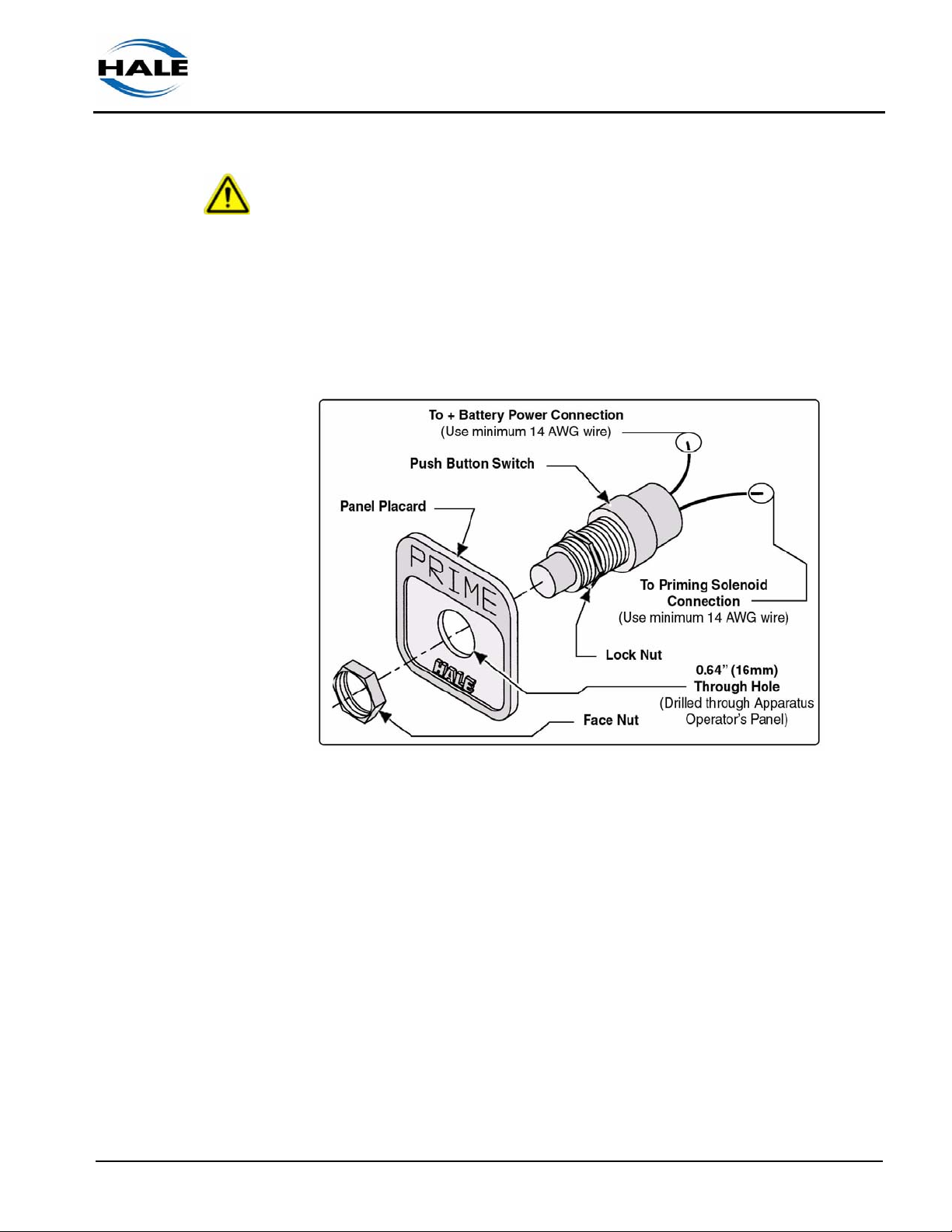
1. Carefully locate the position of the pushbutton switch on the apparatus
operator control panel. (See Figure 3-3: “SPV Pushbutton Placard
Overview.”)
ESP Primer System I nstruction Guide
p/n: 029-0810-01-0
Figure 3-3: SPV Pushbutton Placard Overview
2. Drill or punch a 0.64” (16 mm) diameter hole in the panel.
3. Remove the push button switch from the packaging and install the locknut on the mounting neck.
4. Insert the push button switch through the 0.64” (16 mm) diameter hole
from the back of the operator control panel.
5. Place the PRIME placard over the exposed end of push button switch
on outside of operator panel.
6. Install face nut on push button switch to hold the switch and placard in
place. Tighten locknut and face nut.
7. Using #10 ring terminals on the wire ends
21

❑ Installation
❑ Install minimum 14 AWG type SXL or GXL wire (SAE J1128) from one
switch terminal to the priming pump solenoid connection. Secure the
ring terminal to the push button switch using the screws provided.
(See Figure 3-3: “SPV Pushbutton Placard Overview,” on page 21.)
❑ Install minimum 14 AWG type SXL or GXL wire (SAE J1128) from the
other switch terminal to the positive battery power. Secure the ring
terminal to the push button switch using the screws provided with the
switch.
8. Test operation of the Hale SPV and priming pump. Conduct vacuum
and hydrostatic tests in accordance with department procedures,
NFPA1901 or NFPA 1911.
SPV Retrofit Installation, Midship
When installing the Hale SPV as a “retrofit” on an existing midship fire pump
use the following procedures. (See Figure 3-4: “Typical SPV / Midship
Pump Installation.”)
Figure 3-4: Typical SPV / Midship Pump Installation
1. Place the apparatus out of service in accordance with departmental
procedures.
22
ESP Primer System Instruction Guide
p/n: 029-0810-01-0

Installation ❑
WARNING !
DISCONNECT OR TURN OFF THE MASTER BATTERY SWITCH PRIOR TO
SERVICING THE HALE SPV ELECTRICAL COMPONENTS. MAKE SURE
THERE IS NO POWER AT THE PRIMER SOLENOID BEFORE STARTING SERVICE PROCEDURES.
2. Drain all water from pump body.
3. Open the pump operator panel to gain access to the existing Hale PVG.
4. Disconnect the electrical leads and vacuum hoses to the Hale PVG.
5. If the Hale PVG is mounted at the operator panel, remove the Hale PVG
and placard.
6. Install the panel placard and momentary contact push button provided
with the Hale SPV on the operator panel.
Note: To mount the pushbutton switch, a spacer is required between the placard
and the operator’s panel. Manufacture a spacer using the template in Figure 3-5:
“SPV Retrofit Panel Placard Spacer Layout” as a guide. The outer surface of the
spacer must be flat to allow proper installation of the panel placard push button
switch. Use material thickness and fastening devices that maintain a flat surface.
ESP Primer System I nstruction Guide
p/n: 029-0810-01-0
Figure 3-5: SPV Retrofit Panel Placard Spacer Layout
23

❑ Installation
7. Connect electrical leads to the pushbutton contacts.
8. Locate the priming valve flange on the midship pump. (See Figure 3-4:
“Typical SPV / Midship Pump Installation,” on page 22.) The priming
valve flange is located next to the gearbox on the midship pump.
9. Remove the 7/16”-14 screws that hold the priming flange, hose and fittings on the midship pump body. Remove the flange assembly from the
pump body.
10. Remove the strainer and seal ring from the pump body. Clean the
strainer of all debris. DO NOT discard the strainer as it must be used
with the Hale SPV.
11. Apply a light coat of thread locking compound (Loctite #290 or equivalent) to one end of the 7/16”14 x 1-3/4” long studs. Insert studs into the
pump body where the cap screws were removed then tighten studs.
12. Insert the strainer and seal ring into the pump body, then install Hale
SPV. Make sure the vacuum hose connection is facing in the downward
direction when the SPV is installed.
13. Apply a light coating of thread locking compound (Loctite #290 or equivalent) to the exposed stud threads.
Secure SPV in place using the 7/16”-14 nuts provided.
WARNING !
USE ONLY PIPE, HOSE, AND FITTINGS FROM THE PRIMING PUMP VACUUM
CONNECTION TO THE HALE SPV VACUUM CONNECTION RATED FOR 29 IN.
(737 MM) HG. VACUUM.
14. Attach the 3/4” (19 mm) ID vacuum hose from the hose connection on
the SPV to the priming pump connection. Use hose with 3/4” (19 mm)
inside diameter (ID) that is rated for 29 in. (737 mm) Hg. vacuum (e.g.,
Aeroquip #2556-12 or equivalent).
Make sure the hose is routed and properly secured in place to prevent
chaffing and abrasion.
15. Test operation of the Hale SPV and priming pump. Conduct vacuum
and hydrostatic tests in accordance with department procedures,
NFPA1901 or NFPA 1911.
24
ESP Primer System Instruction Guide
p/n: 029-0810-01-0

Installation ❑
SPV Retrofit Installation, Universal Mount
When installing the Hale SPV assembly with a universal mounting adapter
use the following procedures. (See Figure 3-6: “Typical SPV / Universal
Adapter Pump Installation.”)
ESP Primer System I nstruction Guide
p/n: 029-0810-01-0
Figure 3-6: Typical SPV / Universal Adapter Pump Installation
1. Place the apparatus out of service in accordance with departmental
procedures.
CAUTION !
MAKE SURE THE HALE SPV IS LOCATED HIGHER THAN THE PUMP BODY
ALLOWING WATER TO DRAIN FROM THE VACUUM HOSE.
2. Determine location of the SPV Universal Mounting adapter on the apparatus. When choosing a location make sure there is minimum of 5” (127
mm) clearance for hose connections.
25

❑ Installation
3. Drill two 29/64” (12 mm) holes
2-1/2” (64 mm) apart to attach
the universal mounting
adapter to a secure point on
the apparatus. (See Figure 37: “Universal Mount Adapter
Dimensions.”)
4. Select the proper mounting
adapter orientation and using
the 7/16”14 x 1.0” screws
attach the universal mounting
adapter to the apparatus.
(See Figure 3-8: “Universal
Mount Adapter Positions.”)
5. Apply a light coat of thread
locking compound (Loctite
#290 or equivalent) to one
end of the 7/16”14 x 1-3/4”
studs. Install the studs in the
horizontal holes on the universal adapter. (See Figure
3-8: “Universal Mount Adapter
Positions.”)
Figure 3-7: Universal Mount Adapter
Dimensions
6. Insert strainer and seal ring in the universal adapter, then install Hale
SPV on the universal adapter over the studs. (See Figure 3-6: “Typical
SPV / Universal Adapter Pump Installation,” on page 25.)
Figure 3-8: Universal Mount Adapter Positions
Make sure the vacuum hose connection is facing in the down direction
when the Hale SPV is installed. Additionally, the small drain hole on the
diaphragm cover will be in the down position.
26
ESP Primer System Instruction Guide
p/n: 029-0810-01-0

Installation ❑
7. Apply a light coating of thread locking compound (Loctite #290 or equal)
to the exposed stud threads. Secure the Hale SPV valve in place on the
universal mounting adapter using 7/16-14 nuts.
WARNING !
USE ONLY PIPE, HOSE, AND FITTINGS FROM THE PRIMING PUMP VACUUM
CONNECTION TO THE HALE SPV VACUUM CONNECTION RATED FOR 29 IN.
(737 MM) HG. VACUUM.
8. Attach 3/4” (19 mm) ID vacuum hose from the hose connection on the
Hale SPV to the priming pump connection. Use hose with 3/4” (19 mm)
inside diameter that is rated for 29 in. (737 mm) Hg. vacuum (e.g., Aeroquip #2556-12 or equivalent). Make sure the hose is routed and properly secured in place to prevent chaffing and abrasion.
9. Install a fitting on the side opposite the SPV on the universal adapter.
Connect a 3/4” (19 mm) inside diameter hose rated for 29 in. (737 mm)
Hg. vacuum (e.g., Aeroquip #2556-12 or equivalent) from the priming
tap on the pump body to the hose fitting on the universal mounting
adapter.
10. Test operation of the Hale SPV and priming pump. Conduct vacuum
and hydrostatic tests in accordance with department procedures,
NFPA1901 or NFPA 1911.
PVG Installation
Also see Section Drawing Package, Hale plate drawing “PVG Priming
Valve” on page 54.
1. Place the apparatus out of service in accordance with departmental
procedures.
WARNING !
ESP Primer System I nstruction Guide
p/n: 029-0810-01-0
DISCONNECT OR TURN OFF THE MASTER BATTERY SWITCH PRIOR TO
SERVICING THE HALE PVG ELECTRICAL COMPONENTS. MAKE SURE
THERE IS NO POWER AT THE PRIMER SOLENOID BEFORE STARTING SERVICE PROCEDURES.
2. Drain all water from pump body.
27

❑ Installation
3. Drill or punch one 1.032” (26 mm) and two 0.266” (7 mm) diameter
holes in the panel. (See Figure 3-9: “PVG Panel Placard and Valve
Plumbing Layout.”)
Figure 3-9: PVG Panel Placard and Valve Plumbing Layout
4. Install the PVG panel placard and valve body to the operator’s panel.
(See Figure 3-9: “PVG Panel Placard and Valve Plumbing Layout.”)
5. Secure the assembly with two (2) 1/4”-20 screws. Apply a drop of Loctite #246 to each screw.
6. Install the setscrew, with allen head facing out, into the valve body stem
until the setscrew bottoms-out. Apply a drop of Loctite #246 to the setscrew threads.
7. Install the handle and washer to the valve stud setscrew. Apply a drop
of Loctite #246 to the setscrew threads to assure the handle does not
work loose from use.
8. Install a 3/4” NPT hoes fitting into the PVG valve and connect appropriate 3/4” ID hose between the valve and the primer pump.
9. Install another 3/4” NPT x 1/2” compression hose fitting, rated at 250
PSI minimum, into the side of the PVG valve and connect hose between
the valve and the suction side of the pump. (See Figure 3-9: “PVG
Panel Placard and Valve Plumbing Layout.”)
28
ESP Primer System Instruction Guide
p/n: 029-0810-01-0

Installation ❑
10. Connect the PVG electrical connector to proper system electrical
source. For specification, see Section Drawing Package, Hale plate
drawing “PVG Priming Valve” on page 54.
3.3 LUBRICATED PRIMER INSTALLATION
Also see Figure 3-10: “Typical ESP Lubricated Primer Layout” on page 30.
To convert a Hale ESP Non-Lubricating Priming System to a Lubricated
Priming System, the following parts are required for optimum performance
and to conform to most regional environmental regulations.
❑ Separate lubricant storage tank, Hale p/n: 108-0012-00-0 (4 quart /
3.8 liter capacity).
The tank includes a 1/8” NPT x 5/16” (8 mm) tube fitting with #60 vent
hole.
❑ WARNING ! label for lubricant tank — DO NOT USE ETHYLENE
GLYCOL, provided by installer.
❑ Fluid Capacity Placard (required by NFPA) — installed in the opera-
tor’s cab, provided by installer.
❑ Separate discharge tank, with drain valve and tank breather vent, pro-
vided by installer.
❑ Applicable DOT air brake tubing or soft tubing, 5/16” (8 mm), provided
by installer.
❑ 2-1/2” (64 mm) ID rubber drain / discharge hose, provided by installer.
❑ Tube fittings, 1/8” NPT x 5/16” (8 mm) — (tank fitting provided with
Hale tank).
Installation
WARNINGS !
❑ MAKE SURE THE APPARATUS SYSTEM IS COMPLETELY SHUT-
DOWN, FLUSHED WITH CLEAN, FRESH WATER AND FULLY
DRAINED BEFORE MODIFYING AN EXISTING PRIMER SYSTEM.
ESP Primer System I nstruction Guide
p/n: 029-0810-01-0
❑ FOLLOW YOUR DEPARTMENTAL AND/OR ENVIRONMENTAL REG-
ULATIONS AND THE INSTRUCTIONS RECOMMENDED BY THE
MANUFACTURER AS STATED ON THEIR CONTAINER LABEL.
29

❑ Installation
❑ ALWAYS USE CAUTION WHEN HANDLING OR DISPOSING OF
PROPYLENE GLYCOL.
❑ DO NOT USE ETHYLENE GLYCOL.
The tank should be a translucent, polypropylene tank to allow visual inspection of the lubricant level. Order Hale p/n: 108-0012-00-0 (4 quart / 3.8 liter
capacity), which includes the 1/8” NPT x 5/16” (8 mm) tube fitting with a #60
vent hole. (See Figure 3-10: “Typical ESP Lubricated Primer Layout.”)
WARNINGS - continued !
Figure 3-10: Typical ESP Lubricated Primer Layout
1. The tank should be located within proximity of the primer pump, preferably LEVEL with or BELOW the primer pump. Select a location visible to
the operator for checking and refilling.
30
ESP Primer System Instruction Guide
p/n: 029-0810-01-0

2. Remove the 1/8” NPT
pipe plug in the top of
the primer pump and
install one 1/8” NPT x
5/16” (8 mm) tube fitting. (See Figure 3-11:
“Pump Fittings.”) Use
appropriate thread
sealant.
Note: If the tank is installed
above the primer pump and
is not a Hale tank, the fitting
installed in the top of the
lubricant tank must contain
a vent hole (#60 drill,) in the
top of the fitting to create a
vacuum break (break the
siphon and stop the flow of lubricant when priming stops).
Figure 3-11: Pump Fittings
Installation ❑
3. Run DOT air brake tubing (5/16” /8 mm) from the lubricant storage tank
to the primer pump fitting and secure the tubing (tubing clamps). (See
Figure 3-10: “Typical ESP Lubricated Primer Layout,” on page 30.)
4. Install a separate discharge collection container (tank), three (3) gallons
(11 liters) MINIMUM, to collect all discharged fluid during priming in
accordance with your departmental and/or local environmental regulations.
5. Connect a hose (2-1/2” / 64 mm) from the primer pump discharge to a
separate discharge collection container. Clamp hose using appropriate
hose clamps.
6. Install a tank vent, 1-1/2” (38 mm) MINIMUM at the top of the discharge
tank. (See Figure 3-10: “Typical ESP Lubricated Primer Layout,” on
page 30.)
7. Install a drain valve in the discharge tank to enable easy fluid drainage
and disposal, in accordance with your departmental and/or local environmental regulations.
WARNING !
ESP Primer System I nstruction Guide
p/n: 029-0810-01-0
DO NOT ALLOW COOLANT TO DISCHARGE TO THE GROUND. REVIEW
YOUR DEPARTMENTAL AND/OR LOCAL ENVIRONMENTAL REGULATIONS
REGARDING THE USE OF AND DISPOSAL OF PROPYLENE GYLCOL
COOLANTS.
31

❑ Installation
WARNING - continued !
ALWAYS FOLLOW THE MANUFACTURER’S RECOMMENDED INSTRUCTIONS
ON THE LABEL AFIXED TO THE CONTAINER.
Notes:
❑ DO NOT use water only in the lubricant tank in FREEZING climates.
❑ The propylene glycol must be the type that includes corrosion inhibi-
tors. An example would be propylene glycol antifreeze recommended
for the RV or Marine type cooling systems.
8. Make sure the vent hole in the lubricant tank fitting and discharge tank
breather vent are clean (not clogged or blocked).
9. Fill the tank with an approved propylene glycol coolant - see heading
“Lubricated ESP Primer System” on page 14.
DO NOT USE ETHYLENE GLYCOL.
10. Make sure the drain valve in the discharge collection tank is CLOSED to
prevent accidental discharge to the ground.
11. Install the Fluid Capacity Placard, required by NFPA, inside the operator’s cab. The placard must state “
the lubricant system and should include the lubricant warings listed in the
DO NOT USE ETHYLENE GLYCOL” in
section.
32
ESP Primer System Instruction Guide
p/n: 029-0810-01-0

4 Primer Operation
THE PROCEDURES IN THIS SECTION ARE GENERAL OPERATING PROCEDURES. NOT ALL PROCEDURES IN THIS SECTION MAY APPLY TO YOUR SPECIFIC OPERATIONAL REQUIREMENTS.
THESE PROCEDURES DO NOT REPLACE THE PROCEDURES, POLICIES OR
GUIDELINES ESTABLISHED BY THE AUTHORITY HAVING JURISDICTION, NOR
DO THEY REPLACE THE RECOMMENDATIONS AND PROCEDURES PROVIDED
IN THE APPARATUS MANUFACTURER'S MANUAL.
ALWAYS REFER TO THE PROCEDURES PROVIDED BY THE AUTHORITY HAVING JURISDICTION FOR OPERATING PROCEDURES, SETTING WHEEL
CHOCKS, AS WELL AS LAYOUT AND CONNECTION OF HOSES, VALVES AND
DRAIN COCKS. ALL VALVES, DRAIN COCKS AND CAPS SHOULD BE CLOSED.
Operation ❑
WARNING !
4.1 PRIMING THE PUMP
1. Position the apparatus as close to the water source as practical. The pump
can draw 100% of its rated capacity with less than a 10 foot (3.05 meters)
vertical lift and 20 feet (6 meters) of suction hose.
2. Activate the priming pump - pull the control handle, or press the push
button.
Your departmental manual for pumping should specify the correct RPM for
priming. However, in general, priming should be operated at IDLE.
Running the engine at speeds higher than 1,000 RPM during priming is not
recommended. It does not improve the priming operation but can cause
damage to the pump.
CAUTION !
IF THE DISCHARGE GAUGE READING DOES NOT INCREASE, THE INTAKE
GAUGE READING DOES NOT FALL BELOW ZERO (0), OR THE PRIMING PUMP
DOES NOT DISCHARGE WATER WITHIN 30 TO 45 SECONDS, DO NOT CONTINUE
TO RUN THE PRIMING PUMP.
ESP Primer System Instruction Guide
p/n: 029-0810-01-0
STOP THE PUMP AND CHECK FOR AIR LEAKS OR POSSIBLE PROBLEMS. SEE
SECTION 6 “TROUBLESHOOTING,” ON PAGE 47.
33

❑ Operation
3. Monitor the intake and discharge master gauges. When the pump is
primed, the intake reading falls below zero (0), and the discharge pressure
starts to increase. You may also hear or see water discharging from the
primer, indicating the pump is primed.
4. Gradually open the discharge valve until water emerges in a steady stream.
Then open the other discharge valves to the desired setting.
5. Gradually open the engine throttle until the desired pressure or flow is
achieved.
CAUTION !
DO NOT CAUSE A WHIRLPOOL AT THE STRAINER. THIS ALLOWS AIR INTO THE
PUMP CAUSING ROUGH OPERATION AND PULSATION. REPOSITION THE
STRAINER OR REDUCE FLOW.
DO NOT USE THE PRIMER TO EVACUATE AIR FROM LDH SUPPLY HOSES.
NFPA SPECIFIES AIR BLEEDS FOR THIS PURPOSE. HIGH PRESSURES CAN
DAMAGE THE PRIMER.
Note: Holding the primer ON for about one (1) or two (2) seconds while discharging
water after prime helps keep the primer clean of debris and promotes longer primer
life.
34
ESP Primer System Instruction Guide
p/n: 029-0810-01-0

5 System Maintenance
5.1 GENERAL MAINTENANCE
The following procedures are for normal use and conditions. Extreme conditions may indicate a need for increased maintenance. The procedures in this
section identify measures needed to ensure lengthened pump life and continuing dependability. Always follow local maintenance and test procedures.
Wherever there is a requirement for new parts, it is recommended to use only
Hale authorized replacement parts for optimum safety of the equipment and its
operators and to limit “downtime.”
For a parts breakdown and identification, see Section 7, “Drawing Package” on
page 53.
Maintenance ❑
READ ALL INSTRUCTIONS THOROUGHLY
BEFORE BEGINNING ANY SERVICE REPAIR.
Weekly
Priming System Test
1. Tighten all pump caps, and close all pump valves.
2. Pull the primer control while you watch for a below-zero (0) reading on the
master intake gauge.
3. Continue operation for two (2) or three (3) seconds after the primer starts
flushing water to clear any possible dirt or sludge (gum) buildup. This
buildup affects primer operation by jamming vanes which reduces primer
life.
4. Verify that the master intake gauge readings hold for approximately five (5)
minutes after you release the primer control. A drop of up to 10” Hg. during
this 5 minute period is anticipated per NFPA 1901 standards.
ESP Primer System I nstruction Guide
p/n: 029-0810-01-0
5. If air leaks are heard or the gauge bounces back to or above zero (0), the
pump or valves require service.
35

❑ Maintenance
Monthly
Priming System Test, Dry Vacuum Test
(Refer to NFPA 1901 or NFPA 1911)
1. Close all valves and drains. Cap all suction openings and the outlet of the
suction side relief valve (if so equipped).
2. Connect a test vacuum gauge or manometer to the intake test gauge connection on the pump panel.
3. Engage the priming pump until the gauge indicates
22” Hg. vacuum.
For SPV, press and hold the prime push button to
energize the priming pump motor; for PVG, pull the
primer handle.
4. Compare the readings of the test gauge and the
apparatus gauge. Note any difference.
Figure 5-1: PVG Prim-
ing Valve Handle
5. STOP the priming pump and observe the gauge.
6. If the vacuum falls more then 10” Hg. in five (5) minutes, it is an indication of
at least one air leak.
Vacuum leaks may often be detected by ear if the apparatus engine is
turned OFF.
Correct leaks immediately before returning the pump to service.
7. Test the suction hose as follows:
❑ Attach the suction hose to the pump.
❑ Place the suction tube cap on the end of the hose in place of a strainer.
❑ Close all valves and drains. Cap all suction openings and the outlet of the
suction side relief valve (if so equipped).
❑ Connect a test vacuum gauge or manometer to the intake test gauge con-
nection on the pump panel.
❑ Engage the priming pump until the gauge indicates at least 22” Hg.
36
❑ If the vacuum falls more then 10” in 5 minutes, at least one air leak.
❑ Verify the test gauge and the apparatus gauge display the same readings.
Repair and/or replace gauges that do not display the correct pressure.
ESP Primer System Instruction Guide
p/n: 029-0810-01-0

Maintenance ❑
IMPORTANT !
IF LEAKS CANNOT BE DETECTED BY FOLLOWING THE PROCEDURE, IT IS
ADVISABLE TO TEST THE PUMP HYDROSTATICALLY. TO TEST:
❑ OPEN ALL VALVES
❑ PLACE CAPS ON ALL VALVES
❑ CONNECT A POSITIVE PRESSURE SOURCE (TYPICALLY 250 PSI / 17 BAR)
❑ INSPECT THE PUMP FOR LEAKS
Annually
Clean ESP Priming Pump
Disassemble the priming pump and inspect and clean the housing and vanes.
(See Figure 5-2: “Primer Pump Parts Overview.”)
ESP Primer System I nstruction Guide
p/n: 029-0810-01-0
Figure 5-2: Primer Pump Parts Overview
1. Place apparatus out of service in accordance with your departmental
procedures.
2. Park the vehicle on a level surface. Set the parking brake and chock the
front and rear wheels in accordance with your departmental procedures.
37

❑ Maintenance
3. Match mark, tag and/or note, or photograph the orientation the mechanical
and electrical connections to the primer pump before disassembly. This
aids in proper reassembly.
4. Make sure the main power supply is deactivated, then disconnect the battery connection from the primer solenoid. (See Figure 3-1: “Solenoid Connector Arrangement” on page 18.)
5. Drain the lubrication system main tank, if included, in accordance with your
local departmental procedures and/or environmental regulations.
6. Disconnect the suction inlet, drain (and if included, the lubrication) tubing /
hoses.
7. Disassemble the pump head assembly from the primer motor - 3/8”-16
screws, ground wire and hardware. (See Figure 5-2: “Primer Pump Parts
Overview” on page 37.)
8. Slide the assembly from the motor, then separate the pump body from the
pump head being careful not to drop the rotor vanes.
9. Slide the shaft and rotor assembly from the pump head.
10. Inspect:
❑ Rotor vanes for excessive wear and scaring — replace if necessary.
❑ Inside surface the pump body for scaring or pitting.
❑ Bearings in pump head and body for excessive wear, scoring, etc.
Repair and/or replace parts as needed.
Note: Abrasives passing through the pump can damage sealing surfaces. Corrosion
and/or the breakdown of biodegradable lubricants can cause rotor vanes to stick or
break. Sand entering the pump can cause the vanes to stick or break and can damages the inside wall of the pump body. Replace defective parts.
Wherever there is a requirement for new parts, it is recommended to use only Hale
authorized replacement parts for optimum safety of the equipment and its operators
and to limit “downtime.”
11. Clean all parts of black buildup or contaminates with Safety Kleen or Stoddard Solvent.
12. Check the motor by rotating the motor (insert large screwdriver in slot) to
make sure it turns freely. Also check the rotor vane cylinder assembly for
free spin when installed in bearings.
38
ESP Primer System Instruction Guide
p/n: 029-0810-01-0

Maintenance ❑
13. Reassemble the pump making sure the vanes are inserted properly. (See
Figure 5-2: “Primer Pump Parts Overview” on page 37.)
Use a Lithium-based grease with 1% to 3% Molybdenum Disulfate and
lubricate the rotor cylinder shaft at the bearings.
IMPORTANT !
DO NOT USE A LUBRICANT ON THE ROTOR VANES AND CYLINDER SLOTS.
LUBRICANT AND COLD WATER FORM AN EVENTUAL GUMMY RESIDUE THAT
RENDERS THE PRIMING SYSTEM INOPERATIVE. A COMPLETE AND THOROUGH DISASSEMBLY AND CLEANING IS THEN REQUIRED.
14. Test the system for proper operation — see heading “Priming System Test”
on page 35.
5.2 SPV VALVE REPAIR
The Hale SPV is designed to provide trouble free service with a minimum of
preventive maintenance. Performance degradation can result from a ruptured
diaphragm or worn seat on the valve. A Hale SPV repair kit that contains a
manual, seal ring, valve and diaphragm is available from Hale Products, Inc.
Order Hale repair kit, p/n: 546-1680-00-0. Also see Figure 5-3: “Hale SPV
Parts Overview” on page 40.
1. Disconnect the vacuum hose from the hose connection on the valve body.
Have clean disposable shop rags and oil dry handy.
2. Remove the 7/16”-14 nuts that hold the valve assembly to the pump body or
universal adapter. Remove the valve assembly, strainer and seal ring from
the pump.
3. Match mark, tag and/or note, or photograph the orientation of all mechanical and electrical components and connections before disassembly. This
aids in proper reassembly.
4. Match mark the diaphragm cover and valve body for proper realignment of
the drain hole during re-assembly.
ESP Primer System I nstruction Guide
p/n: 029-0810-01-0
WARNING !
PARTS UNDER SPRING TENSION CAN BECOME PROJECTILES AND CAUSE
SERIOUS INJURY. WHEN REMOVING OR INSTALLING THESE PARTS MAKE
SURE THEY ARE RESTRAINED AND SPRING TENSION IS RELEASED SLOWLY.
39

❑ Maintenance
Figure 5-3: Hale SPV Parts Overview
5. Remove the 5/16”-18 screws that hold the diaphragm cover and diaphragm
to the valve body.
6. Carefully pry the cover and diaphragm from the valve body being careful to
not damage the diaphragm. Separate the cover and diaphragm. (See Figure 5-3: “Hale SPV Parts Overview.”)
7. Support the valve on a stable work surface to prevent accidental release of
spring tension.
8. While pressing in on the diaphragm plate unscrew the #10-24 screw. Once
the screw is removed slowly release the spring tension and remove the diaphragm plate.
9. Remove valve spring, then remove the valve from the valve body.
40
ESP Primer System Instruction Guide
p/n: 029-0810-01-0

Maintenance ❑
10. Remove vacuum hose connection fitting and service elbow from the valve.
11. Inspect all components of the valve for damage and wear. The Hale SPV
repair kit (p/n: 546-1680-00-0) contains a new diaphragm, valve and seal
ring. Always replace these components when the valve is disassembled. If
the brass seat on the valve body is damaged the SPV must be replaced.
12. For Hale recommended cleaners, see heading “Lubricant Specifications” on
page 45.
13. During re-assembly of the valve use thread locking compound (Loctite #290
or equal) to lock threads in place.
14. Apply a light coating of thread sealing compound and install the service
elbow and vacuum hose connection fitting into the valve body.
15. Insert the new valve into the valve body from the side that attaches to the
pump or universal adapter.
16. Place the small end of the compression spring over the boss in the valve
body around the valve.
WARNING !
PARTS UNDER SPRING TENSION CAN BECOME PROJECTILES AND CAUSE
SERIOUS INJURY. WHEN REMOVING OR INSTALLING THESE PARTS MAKE
SURE THEY ARE RESTRAINED AND SPRING TENSION IS RELEASED SLOWLY.
17. With the Hale SPV on a stable surface, place the diaphragm plate over the
spring and press down to compress spring. While holding diaphragm plate
down with spring compressed, install the #10-24 screw into the valve.
18. Place a new diaphragm on the valve body and align screw holes.
19. Place the diaphragm cover over diaphragm aligning match marks assuring
the cover drain hole is in the correct position when the valve is installed on
the pump.
20. Install the 5/16-18 screws to hold the cover in place.
21. Apply a light coating of grease to the seal ring then place strainer and new
seal ring into valve body. Install seal ring, strainer and valve assembly on
pump (or universal adapter) over studs.
ESP Primer System I nstruction Guide
p/n: 029-0810-01-0
Use a Lithium-based grease with 1% to 3% Molybdenum Disulfate. For a
listing, see heading “Lubricant Specifications” on page 45.
41

❑ Maintenance
22. Secure in place using 7/16”-14 nuts - tighten and torque accordingly nuts.
23. Connect the 3/4” (19 mm) ID vacuum hose from the priming pump to the
hose connection fitting on the Hale SPV assembly.
24. Before placing apparatus into operation, test operation of the Hale SPV.
Conduct vacuum and hydrostatic tests in accordance with department
procedures.
5.3 PVG VALVE REPAIR
Figure 5-4: Hale PVG Parts Overview
The Hale PVG is designed to provide trouble free service with a minimum of
preventive maintenance. Over time, performance degradation could result from
a worn O-ring seals, causing leaks, a weakened spring, or a failed electrical
switch. (See Figure 5-4: “Hale PVG Parts Overview.”)
A Hale PVG repair kit is available that contains, O-ring seals (3), and the electrical switch. Order Hale repair kit, p/n: 546-1420-00-0. (See Figure 5-5: “PVG
Valve Parts Breakdown.”)
1. Place apparatus out of service in accordance with your departmental
procedures.
2. Make sure the main power supply is deactivated, then disconnect the valve
connection from the main source.
42
ESP Primer System Instruction Guide
p/n: 029-0810-01-0

Maintenance ❑
Figure 5-5: PVG Valve Parts Breakdown
3. Drain the pump in accordance with your departmental procedures. Have
clean disposable shop rags and oil dry handy.
4. Disconnect the ESP and pump vacuum hoses from the hose connections
on the valve body.
5. Remove both 3/4” fittings in the valve body to allow visible access to the piston and spring.
Insert a screw driver into the cage opening, through the pump port, to hold
the piston from spining as you remove (unscrew) the handle. DO NOT
attempt to secure the brass stem of the piston with vise grips. If the piston
stem is nicked or scratched it will damage the O-ring seal and cause leaks.
6. Remove the PVG valve handle from the valve setscrew stem. (See Figure
5-4: “Hale PVG Parts Overview” on page 42.)
7. Remove the two 1/4”-20 screws securing the valve and placard to the operator’s panel and remove the assembly from the apparatus.
8. Stabilize the unit (in a vise) and remove the two #10-32 screws and washers
from the switch plate. (See Figure 5-5: “PVG Valve Parts Breakdown.”)
ESP Primer System I nstruction Guide
p/n: 029-0810-01-0
9. Remove the switch plate with electrical connector and set safely aside.
43

❑ Maintenance
Note: If the Switch is being replaced only, simple unthread the switch from the plate
and install the new switch.
10. Thread a 3/8”-16 screw into the piston stem, then tap the piston from the
valve body. Remove the spring.
11. Using an O-ring hook-type tool, reach into the valve body and remove the
center valve body O-ring and the piston stem O-ring, Also remove the Oring from the piston and discard all. (See Figure 5-5: “PVG Valve Parts
Breakdown” on page 43.)
12. Examine the piston and valve body bore for defects, e.g., scratches, nicks or
pitting. Repair or replace accordingly.
13. For Hale recommended cleaners, see heading “Lubricant Specifications” on
page 45.
Reassembly Hints
❑ Reassemble the PVG valve by following the preceding steps in reverse
order.
❑ Apply a light film of general purpose grease to the new O-rings and install
two within the body of the valve and one on the piston.
❑ Apply a thin film of grease to the valve piston before inserting into the valve
body.
❑ Use a Lithium-based grease with 1% to 3% Molybdenum Disulfate. For a
listing, see heading “Lubricant Specifications” on page 45.
❑ Apply Loctite #246 to all screws and an appropriate pipe sealant to the 3/4”
NPT pipe threads.
❑ If the switch is removed from the plate, install the plate with the counterbore
side facing the housing mounting bosses. (See Figure 5-4: “Hale PVG Parts
Overview” on page 42.)
❑ Before placing apparatus into operation, the system must be tested and
checked for leaks.
44
ESP Primer System Instruction Guide
p/n: 029-0810-01-0

5.4 LUBRICANT SPECIFICATIONS
Grease, for O-ring Seals
Use a Lithium-based grease with 1% to 3% Molybdenum Dissolved, i.e.,
❑ Dow Corning BR2-PLUS ❑ Lubricate-Fiske #3000
❑ Shell Super Duty Grease ❑ Imperial #777
❑ Mobile Grease Special ❑ Sunoco Moly #2EP
Note: For Hale SVS Torrent Stainless Valves see separate manual for additional
lubrication information.
Loctite Sealant
Maintenance ❑
❑ #246 High Temperature Removable Threadlock (or equivalent) -
primarily for gearbox assembly
❑ #242 Medium Strength Threadlock (or equivalent) - primarily for pump
assembly
Recommended Cleaners
❑ Safety Kleen
IMPORTANT ! The use and disposal of solvents / cleaners must be in accordance with your local environmental regulations.
®
❑ Stoddard Solvent
Lubricants
● Never-Seez®, White Food Grade with PTFE, manufactured by:
Bostik Findley, Inc.
211 Boston Street, Middleton, MA 01949-2128
web: ...................... www.bostikfindley-us.com
ESP Primer System I nstruction Guide
p/n: 029-0810-01-0
45

❑ Maintenance
Notes
______________________________________________________________________
______________________________________________________________________
______________________________________________________________________
______________________________________________________________________
______________________________________________________________________
______________________________________________________________________
______________________________________________________________________
______________________________________________________________________
______________________________________________________________________
______________________________________________________________________
______________________________________________________________________
______________________________________________________________________
______________________________________________________________________
______________________________________________________________________
______________________________________________________________________
______________________________________________________________________
______________________________________________________________________
______________________________________________________________________
______________________________________________________________________
______________________________________________________________________
______________________________________________________________________
______________________________________________________________________
______________________________________________________________________
______________________________________________________________________
______________________________________________________________________
______________________________________________________________________
______________________________________________________________________
______________________________________________________________________
______________________________________________________________________
______________________________________________________________________
______________________________________________________________________
______________________________________________________________________
______________________________________________________________________
______________________________________________________________________
46
ESP Primer System Instruction Guide
p/n: 029-0810-01-0

6 Troubleshooting
Table 6-1 lists conditions, possible causes and suggested corrective action measures. Before calling Hale Products or your Hale authorized parts service center
for assistance, eliminate problem causes using the following table.
If you cannot correct a problem, please have the following information prior to calling the Hale Customer Service for assistance. Contact Customer Service at telephone number 610-825-6300. .
Troubleshooting ❑
Condition
Pump Loses Prime or Will Not Prime.
Possible
Cause
Electric priming system.
Note: Weekly priming is
recommended to ensure
proper operation.
Inoperative priming
system or possible
clogged priming pump.
Suggested Corrective Action
• To prevent possible pump damage, DO NOT EXCEED an engine
speed of 1,000rpm!
• See Section 2.2 “SPV Priming Valve” on page 12. Also see “PVG
Priming Valve” on page 14.
Note: Using lubricant on the vanes and vane slots during disassembly
and cleaning eventually causes a gummy residue to develop, rendering
the system inoperative.
DO NOT LUBRICATE VANES AND VANE SLOTS.
• Check the priming system by performing a “Dry Vacuum Test” per
NFPA standards. If the pump holds vacuum, but primer pulls less
than 22” Hg., it could indicate excessive wear in the primmer.
• See Section 5 Maintenance, heading “Weekly” on page 35.
Also see Section 5 Maintenance, heading “Annually” on page
37.
• See Section 2.2 “SPV Priming Valve” on page 12. Also see
“PVG Priming Valve” on page 14.
• Repair and/or replace accordingly.
Note: Using lubricant on the vanes and vane slots during disassembly and
cleaning eventually causes a gummy residue to develop, rendering the system inoperative.
Suction lifts too high. • DO NOT attempt lifts exceeding 22’ (6.7 meters) except at low
Blocked or restricted
Chart continued on
next page.
ESP Primer System I nstruction Guide
p/n: 029-0810-01-0
suction strainer.
elevation.
• Remove obstruction from suction hose strainer.
• Thoroughly clean strainer screen.
Figure 6-1: Troubleshooting Chart
47

❑ Troubleshooting
Condition
Pump Loses Prime
or Will Not Prime continued.
Possible
Cause
Suggested Corrective Action
Suction connections. • Clean and tighten all suction connections.
• Check suction hose and hose gaskets for possible defects - repair
and/or replace.
Air trapped in suction
line.
• Avoid placing any part of the suction hose higher than the suction
intake.
• Suction hose should be laid out with continuous decline to fluid
supply.
• If trap in hose in unavoidable, repeated priming may be needed to
eliminate air pockets in suction hose.
Insufficient priming. • Proper priming procedures should be followed.
• Do not release the primer control before assuring a complete
prime.
• Open the discharge valve slowly during completion of prime to
ensure complete prime.
NOTICE !
DO NOT RUN THE PRIMER OVER FORTY-FIVE (45) SECONDS. IF PRIME IS NOT
ACHIEVED WITHIN 45 SECONDS, STOP AND LOOK FOR CAUSES
(AIR LEAKS OR BLOCKED SUCTION HOSES).
Pump pressure too low
when nozzle is opened.
• Prime pump again and maintain higher pump pressure while opening the discharge valve slowly.
Chart continued on
next page.
Air leaks. • Attempt to located and correct air leaks using the following proce-
dures:
• Perform “Dry Vacuum Test” on pump per NFPA standards with
22” Hg. minimum vacuum required with loss not to exceed 10”
Hg. in five (5) minutes.
• If a minimum of 22” Hg. cannot be achieved, the priming device
or system may be inoperative, or the leak is too big for the
primer to overcome (such as an open valve). The loss of vacuum indicates leakage and could prevent priming or cause loss
of prime.
• After priming shut OFF the engine. Audible detection of a leak
is often possible.
• Connect the suction hose from the hydrant or the discharge of
another pumper to pressurize the pump with water and look for visible leakage and correct. A pressure of 100 PSI (6.9 BAR / 0.7
MPa) should be sufficient. DO NOT exceed pressure limitations of
pump, accessories or piping connections.
• The suction side relief valve can leak. Plug the valve outlet connection and retest
Figure 6-1: Troubleshooting Chart
48
ESP Primer System Instruction Guide
p/n: 029-0810-01-0

Troubleshooting ❑
Condition
Switch is dead - no click is heard.
See electrical installation detail plate drawing on page 54.
For 12VDC Solenoid,
see Figure 6-2:
“12VDC Solenoid
Arrangement Troubleshooting” on page
50.
For 24VDC solenoid,
see Figure 6-3:
“24VDC Solenoid
Arrangement Troubleshooting” on page
50.
Possible
Cause
Primer Solenoid - 12VDC and 24VDC
Bad base ground. (For
24VDC - bad ground at
(
I ) terminal.)
Low voltage on switch
terminal. (For 24VDC -
bad voltage at (
terminal.)
Dead switch wire.
Bad Battery.
Hardware not properly
tightened.
Check plastic body for
cracks allowing moisture to enter.
S )
Suggested Corrective Action
• Check solenoid base screws for tightness and corrosion, especially
under the hold-down tangs - clean accordingly. Switch base must
be properly grounded to chassis.
• Continuity test and check each cable for defects, i.e., fraying, splits,
corrosion, etc. See electrical installation detail plate drawing on
page 54. Repair and/or replace accordingly.
• Check apparatus battery for full charge - service accordingly.
• Using VOM (volt ohm meter), check wires for proper voltage 12VDC requires minimum of 9.0VDC; 24VDC requires minimum
of 18.0VDC.
• Check that hardware is tight and torqued to specifications. See
mechanical installation detail plate drawing on page 54.
• Hair line cracks in the plastic body allow moisture to enter and
short the internal circuity. If suspect, replace solenoid.
Switch chatters, pops or clicks, but the motor does not work.
Chart continued on
next page.
Bad base ground. (For
24VDC - bad ground at
(
I ) terminal.)
Bad positive (+) or negative (-) cables.
Bad or weak battery.
Low voltage to switch
terminal. (For 24VDC -
bad voltage at (
S )
terminal.)
Hardware not properly
tightened.
Check plastic body for
cracks allowing moisture to enter.
Figure 6-1: Troubleshooting Chart
• Check solenoid base screws for tightness and corrosion, especially
under the hold-down tangs - clean accordingly.
• Continuity test and check each cable for defects, i.e., fraying, splits,
corrosion, etc. See electrical installation detail plate drawing on
page 54. Repair and/or replace accordingly.
• Check that each cable is tight and torqued to specifications. See
mechanical installation detail plate drawing on page 54.
• Check apparatus battery for full charge - service accordingly.
• Using VOM (volt ohm meter), check wires for proper voltage 12VDC requires minimum of 9.0VDC; 24VDC requires minimum
of 18.0VDC.
• Check that hardware is tight and torqued to specifications. See
mechanical installation detail plate drawing on page 54.
• Hair line cracks in the plastic body allow moisture to enter and
short the internal circuity. If suspect, replace solenoid.
ESP Primer System I nstruction Guide
p/n: 029-0810-01-0
49

❑ Troubleshooting
Condition
Switch stays ON (sticks) - motor keeps running.
Notes:
If problems still exists, replace solenoid and recheck all connections and batteries.
It is NOT recommended to put RTV silicone or epoxy over the solenoid connections. Use Never-Seez
Grade with PTFE or a suitable battery spray. Also see Section 5 Maintenance, heading “Lubricants” on page 45.
Positive (+) cable
touching the switch terminal on the solenoid.
Switch wire and cable
wire shorted.
Bad solenoid switch.
Possible
Cause
Suggested Corrective Action
• Check that cables are not touching each other or other objects.
• Continuity test and check each cable for defects, i.e., fraying, splits,
corrosion, etc. Repair and/or replace accordingly.
• Check that each cable is tight and torqued to specifications. See
mechanical installation detail plate drawing on page 54.
• Using VOM, check solenoid for proper opertaion, i.e., solenoid
opens and closes with the control switch. If it does not - replace
solenoid.
• Using VOM (volt ohm meter), check wires for proper voltage 12VDC requires minimum of 9.0VDC; 24VDC requires minimum
of 18.0VDC.
®, White Food
Figure 6-1: Troubleshooting Chart
Figure 6-2: 12VDC Solenoid Arrangement Troubleshooting
50
Figure 6-3: 24VDC Solenoid Arrangement Troubleshooting
ESP Primer System Instruction Guide
p/n: 029-0810-01-0

Limited Warranty
Express Warranty
EXPRESS WARRANTY: Hale Products, Inc. (HALE) hereby warrants to the original Buyer that products manufactured by Hale are free of defects in material and workmanship for two (2) years or 2,000
hours usage, whichever shall first occur. The “Warranty Period” commences on the date the original
Buyer takes delivery of the product from the manufacturer.
LIMITATIONS: Hale’s obligation is expressly conditioned on the Product being:
● Subjected to normal use and service.
● Properly maintained in accordance with Hale’s Instruction Manual as to recommended ser-
vices and procedures.
● Not damaged due to abuse, misuse, negligence, or accidental causes.
● Not altered, modified, serviced (non-routine) or repaired other than by an Authorized Ser-
vice Facility.
● Manufactured per design and specifications submitted by the original Buyer.
THE ABOVE EXPRESS LIMITED WARRANTY IS EXCLUSIVE. NO OTHER EXPRESS WARRANTIES ARE MADE. SPECIFICALLY EXCLUDED ARE ANY IMPLIED WARRANTIES INCLUDING,
WITHOUT LIMITATIONS, THE IMPLIED WARRANTIES OF MERCHANTABILITY OF FITNESS FOR
A PARTICULAR PURPOSE OR USE; QUALITY; COURSE OF DEALING; USAGE OF TRADE; OR
PATENT INFRINGEMENT FOR A PRODUCT MANUFACTURED TO ORIGINAL BUYER’S DESIGN
AND SPECIFICATIONS.
EXCLUSIVE REMEDIES: If Buyer promptly notifies HALE upon discovery of any such defect (within
the Warranty Period), the following terms shall apply:
● Any notice to HALE must be in writing, identifying the Product (or component) claimed
defected and circumstances surrounding its failure.
● HALE reserves the right to physically inspect the Product and require Buyer to return same
to HALE’s plant or other Authorized Service Facility.
● In such event, Buyer must notify HALE for a Returned Goods Authorization Number and
Buyer must return the product F.O.B. within thirty (30) days thereof.
● If determined defective, HALE shall, at its option, repair or replace the Product, or refund
the purchase price (less allowance for depreciation).
● Absent proper notice within the Warranty Period, HALE shall have no further liability or obli-
gation to Buyer therefore.
THE REMEDIES PROVIDED ARE THE SOLE AND EXCLUSIVE REMEDIES AVAILABLE. IN NO
EVENT SHALL HALE BE LIABLE FOR INCIDENTAL OR CONSEQUENTIAL DAMAGE INCLUDING, WITHOUT LIMITATION, LOSS OF LIFE; PERSONAL INJURY; DAMAGE TO REAL OR PERSONAL PROPERTY DUE TO WATER OR FIRE; TRADE OR OTHER COMMERCIAL LOSSES
ARISING, DIRECTLY OR INDIRECTLY, OUT OF PRODUCT FAILURE.
Express Limited Warranty
Hale Products, Inc., 2005
51

Hale Products Inc.
A Unit of IDEX Corporation
700 Spring Mill Avenue
Conshohocken, PA 19428 U.S.A.
Telephone..............1-610-825-6300
Fax ........................1-610-825-6440
Web ........ www.haleproducts.com

ESP Primer System
Drawing Package
Hale Products Inc. ◆ A Unit of IDEX Corporation
700 Spring Mill Avenue
Telephone: 610-825-6300
Web......www.haleproducts.com
◆ Conshohocken, PA 19428 U.S.A.
◆ FAX: 610-825-6440
Click Logo to Select
Manual p/n: 029-0810-01-0

Contents
7 Drawings...................................................................................Plate Number
12 Volt ESP System
Hale ESP-12 Priming System, Mechanical Installation Sheet 1 of 2 ........................................... 821A
Hale ESP-12 Priming System, Electrical Installation Sheet 2 of 2............................................... 821A
24 Volt ESP System
Hale ESP-24 Priming System, Mechanical Installation Sheet 1 of 2 ........................................... 938A
Hale ESP-24 Priming System, Electrical Installation Sheet 2 of 2............................................... 938A
Priming Valves, PVG / SPV
Hale PVG Valve............................................................................................................................ 480A
Hale SPV Valve, Universal Mount ................................................................................................828A
Hale SPV Valve, Pump Mount...................................................................................................... 819A
Manual p/n: 029-0810-01-0, Rev. -A
Printed in U.S.A.
© Hale Products, Inc. 2007
All Rights Reserved


Notes
________________________________________________________________________________________
________________________________________________________________________________________
________________________________________________________________________________________
________________________________________________________________________________________
________________________________________________________________________________________
________________________________________________________________________________________
________________________________________________________________________________________
________________________________________________________________________________________
________________________________________________________________________________________
________________________________________________________________________________________
________________________________________________________________________________________
________________________________________________________________________________________
________________________________________________________________________________________
________________________________________________________________________________________
________________________________________________________________________________________
________________________________________________________________________________________
________________________________________________________________________________________
________________________________________________________________________________________
________________________________________________________________________________________
________________________________________________________________________________________
________________________________________________________________________________________
________________________________________________________________________________________
________________________________________________________________________________________
________________________________________________________________________________________
________________________________________________________________________________________
________________________________________________________________________________________
________________________________________________________________________________________
________________________________________________________________________________________
________________________________________________________________________________________
________________________________________________________________________________________
________________________________________________________________________________________
________________________________________________________________________________________
________________________________________________________________________________________
________________________________________________________________________________________
________________________________________________________________________________________
________________________________________________________________________________________
________________________________________________________________________________________
________________________________________________________________________________________
________________________________________________________________________________________
________________________________________________________________________________________
________________________________________________________________________________________
________________________________________________________________________________________
________________________________________________________________________________________
________________________________________________________________________________________
________________________________________________________________________________________
________________________________________________________________________________________


Notes
_______________________________________________________________________________________________________________
_______________________________________________________________________________________________________________
_______________________________________________________________________________________________________________
_______________________________________________________________________________________________________________
_______________________________________________________________________________________________________________
_______________________________________________________________________________________________________________
_______________________________________________________________________________________________________________
_______________________________________________________________________________________________________________
_______________________________________________________________________________________________________________
_______________________________________________________________________________________________________________
_______________________________________________________________________________________________________________
_______________________________________________________________________________________________________________
_______________________________________________________________________________________________________________
_______________________________________________________________________________________________________________
_______________________________________________________________________________________________________________
_______________________________________________________________________________________________________________


Hale Products, Inc.
A Unit of IDEX Corporation
700 Spring Mill Avenue
Conshohocken, PA 19428
U.S.A.
Telephone ...................610-825-6300
Fax .. ...........................610-825-6440
Web. ............www.haleproducts.com
 Loading...