

TECHNICAL MANUAL
FOR HALE
SINGLE STAGE BOOSTER PUMPS
BY
HALE PRODUCTS, INC.
A Unit of IDEX Corporation
607 NW 27th Ave, Ocala, FL 34475
(800) 533.3569
(800) 520.3473 (FAX)
www.haleproducts.com
MANUAL P/N FSG–MNL–00184 REV A
COPYRIGHT © 2002 – 2018 BY HALE PRODUCTS, INC. ALL RIGHTS RESERVED


TABLE OF CONTENTS
Section Title Page
1. SAFETY ............................................................................................................................................. 1
1.1. PPE ............................................................................................................................................ 1
1.2. Environmental Protection ........................................................................................................ 1
1.3. Training ..................................................................................................................................... 2
1.4. Safety Summary ....................................................................................................................... 2
2. INTRODUCTION................................................................................................................................ 7
2.1. Overview .................................................................................................................................... 7
2.2. How To Use This Manual .......................................................................................................... 7
2.3. Pump Specifications And Numbering ...................................................................................... 8
2.4. Principles Of Operation ............................................................................................................ 8
2.4.1 Explanation Of Terms ......................................................................................................... 9
2.4.1.1 Atmospheric Pressure (Static Air Pressure) ............................................................... 9
2.4.1.2 Cavitation .................................................................................................................. 10
2.4.1.3 Dead Heading ........................................................................................................... 10
2.4.1.4 Impeller And Clearance Rings ................................................................................. 10
2.4.1.5 Priming Pump ........................................................................................................... 10
2.4.1.6 Relief Valve ............................................................................................................... 10
2.4.1.7 PM Relief Valve Control ............................................................................................ 11
2.4.1.8 Volute ........................................................................................................................ 11
2.4.2 Standard Booster Pump Components ............................................................................ 11
2.4.2.1 Volute
2.4.2.2 Impeller And Shaft Assembly ................................................................................... 12
2.4.2.3 Mechanical Seal ....................................................................................................... 12
2.4.2.4 Gearbox ..................................................................................................................... 13
........................................................................................................................ 12
2.5. Pump Drives ........................................................................................................................... 13
2.6. Optional Pump Components ................................................................................................. 14
2.6.1 Anodes ............................................................................................................................. 14
2.6.2 TRVs ................................................................................................................................. 15
i

TABLE OF CONTENTS – CONTINUED
Section Title Page
3. MAINTENANCE OPERATING PROCEDURES ................................................................................. 17
3.1. Repair Verification Operations .............................................................................................. 18
3.2. Vacuum Test ........................................................................................................................... 20
3.3. Pressure Test ......................................................................................................................... 22
3.4. Pumping From Draft Verification Operations ....................................................................... 23
3.4.1 Draft Limiting Factors ....................................................................................................... 25
3.5. Cavitation (Details) ................................................................................................................. 26
3.5.1 Process Of Cavitation ...................................................................................................... 26
3.5.2 Warning Signs Of Cavitation ........................................................................................... 27
3.5.2.1 Discharge Pressure ................................................................................................... 27
3.5.2.2 Vacuum Compound Gauge....................................................................................... 27
3.5.3 How To Prevent Cavitation .............................................................................................. 27
3.5.3.1 General Considerations ............................................................................................ 28
3.5.3.2 During Operations ..................................................................................................... 29
3.6. Post Operation Procedure ....................................................................................................... 30
4. PREVENTIVE MAINTENANCE ......................................................................................................... 31
4.1. Preventive Maintenance Plan And Schedule ....................................................................... 31
4.2. Maintenance Log ................................................................................................................... 33
4.3. Extreme Conditions Maintenance Guidelines ...................................................................... 34
4.3.1 Freezing Weather ............................................................................................................ 34
4.3.2 Contaminated Water ................................................................................................
4.4. Booster Pump Preventive Maintenance Procedures ........................................................... 35
4.4.1 After Each Use (Flush Pump) .......................................................................................... 35
4.4.2 Leakage Checks .............................................................................................................. 35
4.4.3 Quarterly Maintenance.................................................................................................... 36
....... 35
4.4.3.1 Check Gearbox Oil Level ........................................................................................... 36
4.4.3.2 Perform Vacuum Test ............................................................................................... 37
4.4.4 Annual Pump Maintenance ............................................................................................ 38
4.4.4.1 Performance Testing ................................................................................................. 38
4.4.4.1.1 Testing Overview ................................................................................................. 38
ii

TABLE OF CONTENTS – CONTINUED
Section Title Page
4.4.4.1.2 Testing Equipment And Materials ..................................................................... 38
4.4.4.1.3 Performance Testing Test Procedure ............................................................... 41
4.4.5 Annual Pump Maintenance ............................................................................................ 41
4.4.6 Triennium Pump Maintenance ....................................................................................... 42
4.4.6.1 Gearbox Fluid Change .............................................................................................. 42
5. CORRECTIVE MAINTENANCE (REPAIR) ....................................................................................... 43
5.1. Troubleshooting ..................................................................................................................... 43
5.1.1 PTO Or Pump Engagement Problems ............................................................................ 43
5.1.2 Pump Priming Problems ................................................................................................. 44
5.1.3 Insufficient Pump Capacity ............................................................................................. 45
5.1.4 Engine Speed Problems ................................................................................................. 45
5.1.5 Relief Valve Problems ..................................................................................................... 46
5.1.6 Gearbox Problems........................................................................................................... 46
5.1.7 Discharge Valve Problems .............................................................................................. 46
5.1.8 Cavitation......................................................................................................................... 47
5.2. Maintenance Level 1 ............................................................................................................. 48
5.3. Maintenance Level 2 ............................................................................................................. 48
5.4. Maintenance Level 3 ............................................................................................................. 48
5.5. Maintenance Impeller Renew ............................................................................................... 48
5.6. Miscellaneous Maintenance ................................................................................................. 49
5.7. General Repair Guidelines ................................................................................................
5.7.1 Match Mark Or Note Component Orientation ............................................................... 49
5.7.2 Recommended Lubricants ............................................................................................. 49
5.7.3 Cleaning And Lubrication Required For Mechanical Seal Installation ........................ 50
5.7.4 Replacement Fasteners ................................................................................................. 50
.... 49
5.7.5 Circlip/Snap Ring Installation ........................................................................................ 51
5.7.6 Thread Lock Or Sealant Compound ............................................................................... 51
5.7.7 Cleaning And Inspection Guidelines .............................................................................. 51
5.7.7.1 Recommended Cleaners ......................................................................................... 52
5.7.8 Repair Kits ....................................................................................................................... 52
iii

TABLE OF CONTENTS – CONTINUED
Section Title Page
5.7.9 Impeller Renew Kits ........................................................................................................ 52
5.7.9.1 Worn Clearance Rings And Impeller Hubs............................................................... 52
5.8. Removal And Replacement Instruction Guidelines ............................................................. 54
5.8.1 Tools Required/Suggested ............................................................................................. 54
5.8.2 General Pump Disassembly For Access Guidelines ...................................................... 55
5.8.2.1 General Pump Removal From The Apparatus ......................................................... 56
5.8.3 General Pump Disassembly Methodology ...................................................................... 58
5.8.4 Level 1 Procedures .......................................................................................................... 67
5.8.4.1 RSD Suction Head R&R ............................................................................................ 67
5.8.4.2 RSD Volute R&R ........................................................................................................ 69
5.8.4.3 AP/MBP Volute R&R ................................................................................................. 72
5.8.4.4 CBP Volute R&R ........................................................................................................ 74
5.8.4.5 MBP/RSD Inducer R&R ............................................................................................ 76
5.8.4.6 MBP/RSD Impeller R&R ........................................................................................... 81
5.8.4.7 AP Impeller R&R ........................................................................................................ 83
5.8.4.8 CBP Impeller R&R ..................................................................................................... 87
5.8.4.9 AP/CBP/MBP Mechanical Seal R&R ....................................................................... 90
5.8.4.10 RSD Mechanical Seal R&R ....................................................................................... 93
5.8.4.11 AP/CBP/MBP Pump Head R&R ............................................................................... 96
5.8.4.12 RSD Pump Head R&R ............................................................................................... 98
5.8.4.13 Pump Head R&R Bench Procedures .................................................................... 102
5.8.4.13.1 Pump Shaft Oil Seal Bench Procedure........................................................... 102
5.8.4.13.2 RSD Mechanical Seal Anti Rotation Pin Bench Procedure ........................... 103
5.8.5 Level 2 Procedures ....................................................................................................... 105
5.8.6 Level 3 Procedures ....................................................................................................... 105
5.8.7 Miscellaneous Procedures ........................................................................................... 106
5.8.7.1 Cooling System ....................................................................................................... 106
5.8.7.1.1 Cooling Tube R&R ............................................................................................ 108
5.8.7.2 Pump Clearance Ring R&R .................................................................................... 110
5.8.8 General Install On The Apparatus ............................................................................... 117
iv

TABLE OF CONTENTS – CONTINUED
Section Title Page
5.9. Gearbox ................................................................................................................................ 118
5.9.1 Gearbox R&R ................................................................................................................. 118
5.9.2 Gearbox Bench Procedures .......................................................................................... 120
5.9.2.1 Input Shaft .............................................................................................................. 121
5.9.2.1.1 Input Shaft Oil Seal (ONLY).............................................................................. 126
5.9.2.1.2 Input Shaft Bearings (ONLY) ........................................................................... 127
5.9.2.1.3 Input Shaft Endcap (ONLY) .............................................................................. 128
5.9.2.1.4 Drive Gear (Input Shaft) ................................................................................... 129
5.9.2.2 Pump Shaft ............................................................................................................. 131
5.9.2.2.1 Pump Shaft Bearings (ONLY) .......................................................................... 139
5.9.2.2.2 Pump Shaft Endcap (ONLY) ............................................................................. 139
5.9.2.2.3 Pump Gear (ONLY) ........................................................................................... 141
APPENDIX A. TIGHTENING (TORQUE) INFORMATION ................................................................ A–1
APPENDIX B. TEST EQUIPMENT AND SPECIAL TOOL INFORMATION ....................................... B–1
B.1. SPECIAL TOOL INFORMATION ............................................................................................. B–1
APPENDIX C. ANCILLARY PUMP EQUIPMENT ............................................................................ C–1
C.1. PRIMING SYSTEMS .............................................................................................................. C–1
C.1.1 Priming Pump ................................................................................................................ C–1
C.1.2 Priming Valves ............................................................................................................... C–2
C.2. TEMPERATURE CONTROL DEVICES .................................................................................... C–4
C.2.1 TRV ................................................................................................................................. C–4
C.2.2 TRV–L Kit ....................................................................................................................... C–4
C.3. ANCILLARY EQUIPMENT PREVENTIVE MAINTENANCE PROCEDURES ............................. C–5
C.3.1 Weekly Maintenance .................................................................................................... C–5
C.3.1.1 Pump Shift Warning Indicator Lights ..................................................................... C–5
C.3.1.2 Check Valves ........................................................................................................... C–5
C.3.1.3 Check And Clean Intake Strainers ......................................................................... C–5
C.3.1.4 Check All Gauges .................................................................................................... C–5
C.3.1.5 Check Pump Controls ............................................................................................. C–5
C.3.1.6 Inspect Water and Foam Tanks ............................................................................. C–5
v
FSG–MNL–00184 REVISION HISTORY
CHANGE
DATE
AFFECTED PAGES
TABLE OF CONTENTS – CONTINUED
Section Title Page
C.3.1.7 Check Roof and Bumper Turrets ........................................................................... C–5
C.3.1.8 Check Auxiliary Fire Suppression Equipment ....................................................... C–6
C.3.2 Monthly Maintenance .................................................................................................. C–6
C.3.2.1 Priming System Test (Dry Vacuum Test) ............................................................... C–6
C.3.2.2 Drive Line And Flange Bolts .................................................................................. C–7
C.3.3 Annual Maintenance .................................................................................................... C–8
C.3.3.1 Check Drain Lines to Multi-Drain .......................................................................... C–8
C.3.3.2 Tank To Pump Flow Rate Test ............................................................................... C–8
C.3.3.3 ESP Primer Maintenance....................................................................................... C–9
APPENDIX D. OPERATOR MAINTENANCE LOG .......................................................................... D–1
APPENDIX E. MANUFACTURER'S INFORMATION ....................................................................... E–1
E.1. Manufacturer's Information ................................................................................................ E–1
E.2. Warranty ............................................................................................................................... E–1
E.3. Returned Goods Procedure ................................................................................................. E–1
Revision A 8 May 2019 All – Initial Release
vi

LIST OF FIGURES
Number Title Page
Figure 1. Centrifugal Force From A Rotating Disk ........................................................................... 8
Figure 2. Single Stage Water Flow ................................................................................................... 9
Figure 3. Clearance Ring Water Flow ............................................................................................ 10
Figure 4. Parts Of The Hale Booster Pump ................................................................................... 11
Figure 5. Mechanical Seal ............................................................................................................. 12
Figure 6. Direct Engine Mount ....................................................................................................... 14
Figure 7. Hale Anode ...................................................................................................................... 14
Figure 8. Driver Compartment Indicator Lights ............................................................................ 18
Figure 9. Pump Operator Panel ..................................................................................................... 19
Figure 10. Results Of Cavitation .................................................................................................. 26
Figure 11. Low Pressure Regions ................................................................................................ 27
Figure 12. Typical Gearbox Oil Fill/Level Component Locations ............................................... 36
Figure 13. Engine Or Opposite Engine Rotation ......................................................................... 47
Figure 14. Circlips (How To Recognize And Remove Them) ...................................................... 51
Figure 15. Measuring For Worn Clearance Rings And Impeller Hubs ....................................... 53
Figure 16. Seal Removal Tool And Seal Driver Kit ...................................................................... 55
Figure 17. Caliper (Depth Rod Extended) ................................................................................... 55
Figure 18. Pump And Gearbox Assembly R&R ........................................................................... 57
Figure 19. One-Piece Volute (AP, CBP, MBP) .............................................................................. 59
Figure 20. Three-Piece Volute (RSD) ........................................................................................... 59
Figure 21. AP Pump Exploded View ............................................................................................. 61
Figure 22. CBP Pump Exploded View .......................................................................................... 62
Figure 23. MBP Pump Exploded View ......................................................................................... 63
Figure 24. RSD Pump Exploded View .......................................................................................... 64
Figure 25. Gearbox Exploded View (All Except 3.74:1 GR) ........................................................ 65
Figure 26. Gearbox Exploded View (3.74:1 GR) ......................................................................... 66
Figure 27. AP/MBP Volute R&R ................................................................................................... 72
Figure 28. MBP Inducer R&R ....................................................................................................... 77
Figure 29. RSD Inducer R&R ....................................................................................................... 77
Figure 30. MBP Impeller R&R ...................................................................................................... 82
Figure 31. AP Impeller R&R ......................................................................................................... 84
Figure 32. CBP Impeller R&R ....................................................................................................... 87
Figure 33. NORD-lock Washers Installation Details ................................................................... 89
Figure 34. Typical Mechanical Seal Detail .................................................................................. 91
Figure 35. RSD Mechanical Seal Notch ...................................................................................... 94
Figure 36. Align Slot On Seal With Pin In Pump Head ................................................................ 95
Figure 37. Pump Head (Pump Side) .......................................................................................... 100
Figure 38. Pump Head (Drive Side) ........................................................................................... 101
Figure 39. Slots Cut In Clearance Ring–Volute......................................................................... 111
Figure 40. Clearance Ring Driven Out–Volute .......................................................................... 111
vii

LIST OF FIGURES – CONTINUED
Number Title Page
Figure 41. Wrap Around Clearance Rings – Pump Heads ....................................................... 113
Figure 42. Clearance Ring Drilled Out (MPB Pump Head) ....................................................... 113
Figure 43. Clearance Ring Bent Inward And Cut Thru ............................................................. 113
Figure 44. Slots Cut In Clearance Ring - Suction Head ........................................................... 115
Figure 45. Clearance Ring Driven Out – Suction Head............................................................ 115
Figure 46. RSD Wrap Around Clearance Rings ........................................................................ 116
Figure 47. RSD Wrap Around Clearance Ring R & R ................................................................ 117
Figure 48. Pump Shaft Assembly .............................................................................................. 133
Figure 49. AP/CBP Pump Shaft ................................................................................................. 135
Figure 50. MBP/RSD Pump Shaft ............................................................................................. 136
Figure 51. Rotary Vane Positive Displacement Type Priming Pump ....................................... C–1
Figure 52. Rotor And Vanes ....................................................................................................... C–2
Figure 53. ESP Priming Pump ................................................................................................... C–2
Figure 54. PVG Priming Valve .................................................................................................... C–3
Figure 55. SPVR Priming Valve .................................................................................................. C–3
Figure 56. TRV ............................................................................................................................ C–4
Figure 57. TRV–L ........................................................................................................................ C–4
Figure 58. Engage Priming Pump .............................................................................................. C–6
Figure 59. Grade 8 Bolt Marking ............................................................................................... C–7
Figure 60. Class 10.9 Bolt Marking .......................................................................................... C–7
Figure 61. ESP Exploded View ................................................................................................... C–9
Figure 62. ESP-PVG Primer Repair Kit (P/N 546-1410-03-0) ............................................... C–10
LIST OF TABLES
Number Title Page
Table 1. Vacuum Test Tools And Consumables List .................................................................... 20
Table 2. Pressure Test Tools And Consumables List .................................................................. 22
Table 3. Additional Losses Beyond NFPA Rating Baseline ......................................................... 25
Table 4. Hose Sizes For Pump Rating Capacity ........................................................................... 28
Table 5. Lift Loss From Barometric Pressure .............................................................................. 29
Table 6. Lift Loss From Elevation ................................................................................................. 29
Table 7. Recommended Preventive Maintenance – Pump ........................................................ 31
Table 8. Recommended Preventive Maintenance – Ancillary Equipment ................................. 32
Table 9. Example Performance Test ............................................................................................ 38
Table 10. Pressure And Flow For Various Size Nozzles ................................................................. 39
viii

LIST OF TABLES – CONTINUED
Number Title Page
Table 11. Engagement SCR Table .................................................................................................. 43
Table 12. Pump Priming SCR Table ............................................................................................... 44
Table 13. Insufficient Pump Capacity SCR Table .......................................................................... 45
Table 14. Engine Speed SCR Table ................................................................................................ 45
Table 15. Relief Valve SCR Table ................................................................................................... 46
Table 16. Gearbox SCR Table ......................................................................................................... 46
Table 17. Discharge Valve(s) SCR Table ........................................................................................ 46
Table 18. Cavitation SCR Table ...................................................................................................... 47
Table 19. Rotation SCR Table ......................................................................................................... 47
Table 20. Recommended O-ring Lubricant .................................................................................... 49
Table 21. Recommended Mechanical Seal Lubricant .................................................................. 50
Table 22. Maximum Torque Values ............................................................................................... 50
Table 23. Impeller And Clearance Ring Diameters And Clearance Values.................................. 53
Table 24. Pump R&R From The Apparatus Tools And Consumables List .................................... 56
Table 25. RDS Suction Head R&R Tools And Consumables List .................................................. 67
Table 26. RSD Volute R&R Tools And Consumables List.............................................................. 70
Table 27. AP Volute R&R Tools And Consumables List ................................................................ 72
Table 28. CBP Volute R&R Tools And Consumables List .............................................................. 74
Table 29. MBP/RSD Inducer R&R Tools And Consumables List .................................................. 78
Table 30. MBP/RSD Impeller R&R Tools And Consumables List ................................................. 82
Table 31. AP Impeller R&R Tools And Consumables List ............................................................. 84
Table 32. CBP Impeller R&R Tools And Consumables List
Table 33. AP/CBP/MBP Mechanical Seal Bench Procedure Tools And Consumables List........ 90
Table 34. RSD Mechanical Seal Bench Procedure Tools And Consumables List ....................... 93
Table 35. AP/CBP/MBP Pump Head R&R Tools And Consumables List ..................................... 97
Table 36. RSD Pump Head R&R Tools And Consumables List .................................................... 99
Table 37. Pump Shaft Oil Seal Bench Procedure Tools And Consumables List ........................ 102
Table 38. Mechanical Seal Pin Bench Procedure Tools And Consumables List ....................... 104
Table 39. Gearbox Cooling Tube R&R Tools And Consumables List .......................................... 107
Table 40. Pump Clearance Ring R&R Tools And Consumables List .......................................... 110
Table 41. Input Shaft Bench Procedure Tools And Consumables List ...................................... 121
Table 42. Input Shaft Oil Seal Bench Procedure Tools And Consumables List ......................... 126
Table 43. Input Shaft Endcap Bench Procedure Tools And Consumables List ......................... 128
Table 44. Drive Gear Bench Procedure Tools And Consumables List ....................................... 130
Table 45. Pump Shaft Bench Procedure Tools And Consumables List ..................................... 131
Table 46. Pump Shaft Endcap R&R Tools And Consumables List ............................................. 139
Table 47. Pump Gear Bench Procedure Tools And Consumables List ...................................... 142
........................................................... 88
ix

ESP
Environmentally Safe Priming
gpm
Gallons Per Minute
Abbreviations And Acronyms
The abbreviations used in this manual are limited to standard (commonly used and accepted)
scientific units of measure and therefore are NOT defined or listed. The acronyms used in this
manual are defined in this listing (in numerical-alphabetical order) and are NOT defined within
the text.
AKA Also Known As
AP Attack Pump
CBP Centrifugal Booster Pump
CCW Counter Clockwise
CW Clockwise
EVT Emergency Vehicle Technician
FAST Factory Authorized Service Team
GR Gear Ratio
ID Inside Diameter
Lpm Liters Per Minute
N/A Not Applicable
NFPA National Fire Protection Act
NFPA 1901 Standard For Automotive Fire Apparatus
NFPA 1911 Standard For The Inspection, Maintenance, Testing, And Retirement Of In-
Service Automotive Fire Apparatus
NLGI National Lubrication Grease Institute
NPT Normal Pipe Thread
OEM Original Equipment Manufacturer
OD Outside Diameter
PM Panel Mounted
PMD Panel Mounted Display
PPE Personal Protection Equipment
PTO Power Take Off
R&R Removal and Replacement (Installation)
RSD Removable Side Drive
SAE Society of Automotive Engineers
SCR Symptom, Cause, Remedy (Troubleshooting Table)
SPV Semi-automatic Priming Valve
SPVR Suction Pressure Relief Valve
TRV Thermal Relief Valve
x
1. SAFETY
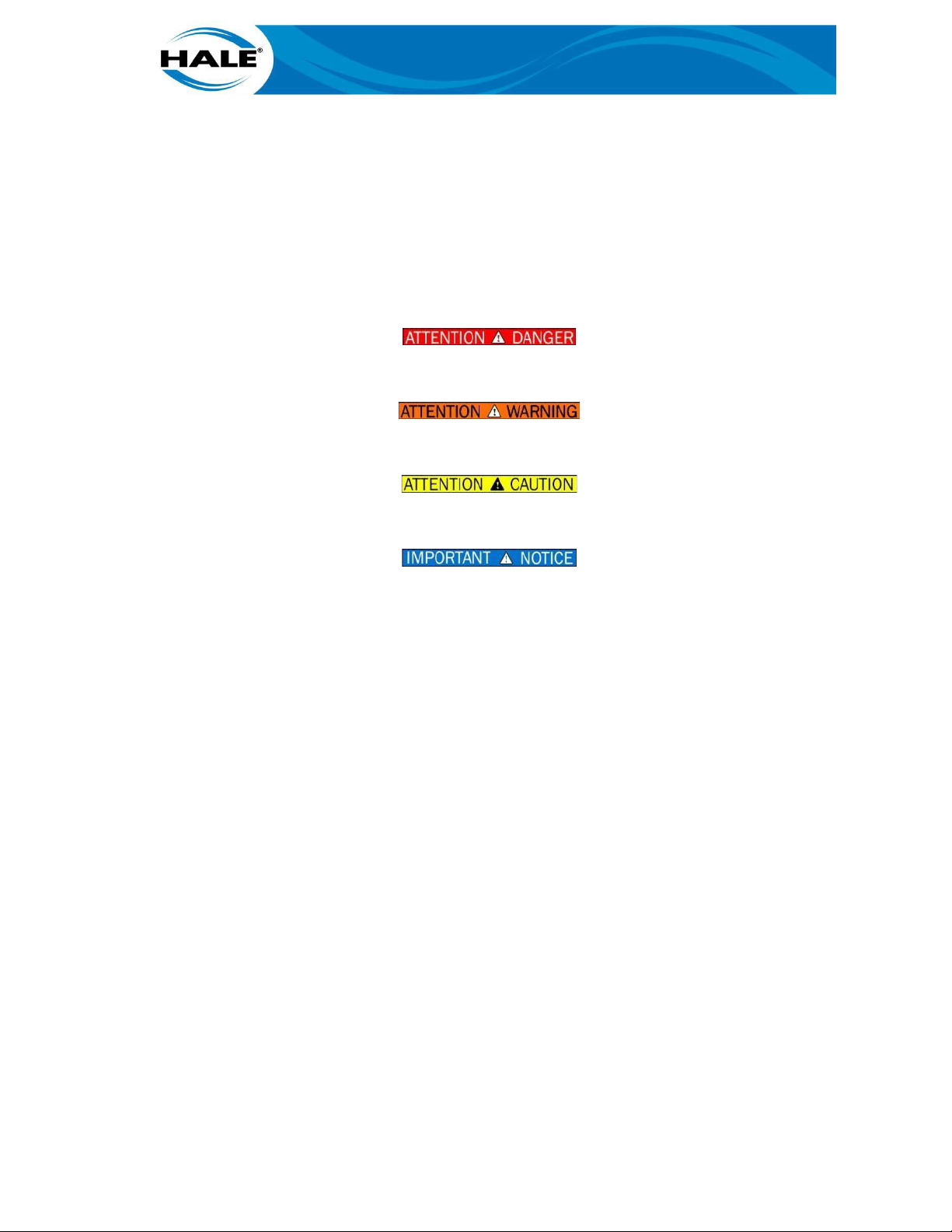
This section provides definitions for DANGERS, WARNINGS, CAUTIONS, NOTICES, and NOTES
contained herein, precautions to be taken for pump repair as well as an alphabetical summary
listing of the DANGERS, WARNINGS, CAUTIONS, and NOTICES used in this manual.
DANGERS, WARNINGS, CAUTIONS, or NOTICES that immediately precede a step apply directly to
that step and all sub steps. DANGERS, WARNINGS, CAUTIONS, or NOTICES that precede an entire procedure apply to the entire procedure. WARNINGS and CAUTIONS consist of two parts: a
heading (that identifies possible result if disregarded) and a statement of the hazard (that provides the minimum precautions). The headings used and their definitions are.
INDICATES A HAZARDOUS SITUATION, WHICH IF NOT AVOIDED WILL RESULT IN SERIOUS INJURY OR DEATH.
INDICATES A HAZARDOUS SITUATION, WHICH IF NOT AVOIDED COULD RESULT IN
SERIOUS INJURY OR DEATH.
INDICATES A POTENTIALLY HAZARDOUS SITUATION, WHICH IF NOT AVOIDED MAY
RESULT IN MINOR OR MODERATE INJURY.
ADDRESSES PRACTICES NOT RELATED TO PERSONAL INJURY.
NOTE
Highlights an essential aspect of an operating or maintenance procedure, condition,
or statement and/or provides pertinent ancillary information.
NOTES may precede or follow the step or procedure, depending upon the information and how it
pertains to the procedure/step. The headings used and their definitions are.
1.1. PPE
The following is the minimum PPE required when performing maintenance.
• Safety Glasses • Work Shoes (Steel Toe)
• Safety Gloves • Ear Protection
• General Protection • Single Use
• Chemical Resistant • Ear Muffs
1.2. Environmental Protection
Used oil from the gearbox must be disposed of in accordance with your local regulations. It is
prohibited to pour oil and other contaminants onto the ground, down sewers, drains, or into water courses. Dispose of lubricants through authorized waste disposal contractors, licensed waste
disposal sites, or to the waste reclamation trade. If in doubt, contact your Local Environmental
Agency for advice regarding disposal policies.
1

1.3. Training
AP, CBP, MBP, and RSD pumps must only be operated and maintained by trained personnel.
Training is available via the Hale Products Inc. website (www.haleproducts.com), Godiva √erified
Training (godiva.co.uk), or through your local dealer or vehicle manufacturer. The Hale website
provides a description of the course content and general information about the training, including an invitation to register with the EVT Certification Commission (www.evtcc.org) to take one
EVT exam at the Hale facility.
NOTE
Be sure to record the contact phone number and contact person’s information before
completing the form.
Complete the SESSIONS, ORGANIZATION CONTACT INFORMATION, STUDENT CONTACT INFORMATION portions of the form. Check the Captcha (provides the proof of human input) and then
click the SUBMIT button at the bottom of the page.
NOTE
Under the FAST buttons select No unless your facility is a FAST center. Do NOT click
Yes unless you know for sure you are a FAST member requiring certification or recertification (a certification is valid for 4 years).
When the Thank you for Registering page appears record the halemarketing email address (Add
this address to your email address book to prevent your response from being routed to the Junk
folder.) and call the contact phone number (recorded earlier) to arrange payment.
NOTE
Due to demand, classes fill far in advance of the scheduled dates. The ONLY way to
hold the selected dates is to pay at the time of enrollment submission.
1.4. Safety Summary
DO’S
• When installing or removing the pump, use ONLY appropriately rated lifting equipment that
has been inspected and is in good condition.
• Use/wear all required PPE when operating the pump (including for maintenance purposes).
See paragraph 1.1, PPE.
DON’TS
• Do NOT remove guards; rotating parts must be guarded against accidental contact.
• Do NOT insert items into the suction tube when pump is running.
• Do NOT disconnect discharge hoses while the unit is running.
• Do NOT loosen/unfasten/remove components while the unit is running.
The following warnings and cautions are used throughout this manual and are provided here as
a safety summary. WARNINGS or CAUTIONS within a procedure (preceding an individual step),
apply directly to that step, however WARNINGS or CAUTIONS that precede the entire procedure,
apply to the ENTIRE procedure.
2
A PRESS PRESENTS A POTENTIAL CRUSH HAZARD (FROM MOVING PARTS) AND/OR
STRIKE HAZARD (FROM EJECTED PARTS). WEAR APPROPRIATE PPE.
A PRESSURE HAZARD MAY EXIST EVEN WHEN THE PUMP IS NOT RUNNING. PRIOR
TO REMOVING HOSES OR CAPS FROM PUMP CONNECTIONS, RELIEVE PRESSURE BY
OPENING DRAINS. BLEEDER VALVES SHOULD ALSO BE USED WHEN CONNECTING
TO AN INTAKE FROM A PRESSURIZED SOURCE.
ALWAYS FOLLOW LOCAL GUIDELINES FROM THE AHJ AND THE APPARATUS MANUFACTURER.
ALWAYS FOLLOW PROPER OPERATING PROCEDURES. THE PUMP OPERATOR MUST
BE FAMILIAR WITH THE PUMP OPERATING INSTRUCTIONS AS WELL AS OTHER OPERATING GUIDELINES FOR THE APPARATUS AND ACCESSORIES.
DO NOT EXCEED OPERATING PRESSURE LIMITS OF PUMP, INSTALLED PLUMBING,
HOSE(S), OR EQUIPMENT IN USE.
DO NOT LEAVE THE CAB OR ATTEMPT TO PUMP UNTIL ALL OK TO PUMP LIGHTS IN
THE CAB ARE ILLUMINATED. SEE FIGURE 7.
OPERATORS, INSTALLERS, AND MAINTENANCE PERSONNEL MUST BE TRAINED AND
QUALIFIED FOR ALL THE ACTIVITIES THEY PERFORM.
ALWAYS USE PROPER PPE. OIL MAY BE TOXIC TO PEOPLE AND/OR THE ENVIRONMENT. CATCH AND DISPOSE OF OIL PROPERLY. IMPROPER OIL HANDLING MAY RESULT IN HEALTH RISKS AND/OR CRIMINAL PUNISHMENTS.
FAILING TO REDUCE SYSTEM PRESSURE BEFORE SYSTEM SHUTDOWN OR FLUSHING COULD RESULT IN WATER HAMMERING.
THE AP PUMP AND GEARBOX ASSEMBLIES WEIGH APPROXIMATELY 140 LBS
(64 KG). USE PROPER LIFTING DEVICE WHEN REMOVING OR INSTALLING THE PUMP
AND GEARBOX ASSEMBLY.
THE CBP PUMP AND GEARBOX ASSEMBLIES WEIGH APPROXIMATELY 100 LBS
(45 KG). USE PROPER LIFTING DEVICE WHEN REMOVING OR INSTALLING THE PUMP
AND GEARBOX ASSEMBLY.
THE MBP PUMP AND GEARBOX ASSEMBLIES WEIGH APPROXIMATELY 170 LBS
(77 KG). USE PROPER LIFTING DEVICE WHEN REMOVING OR INSTALLING THE PUMP
AND GEARBOX ASSEMBLY.
3
THE RSD PUMP AND GEARBOX ASSEMBLIES WEIGH APPROXIMATELY 225 LBS
(102 KG). USE PROPER LIFTING DEVICE WHEN REMOVING OR INSTALLING THE
PUMP AND GEARBOX ASSEMBLY.
USE PPE TO PROTECT HANDS AND FINGERS FROM SHARP EDGES. THE EDGES OF
THE BLADES ON THE INDUCER MAY BE SHARP.
A MECHANICAL SEAL IS A PRECISION ENGINEERED DEVICE. CARE MUST BE TAKEN
NOT TO DAMAGE THE MATING FACES (SEAL FORMING PORTION) OF THE SEAL. ENSURE THE FACES REMAIN ABSOLUTELY CLEAN THROUGHOUT THE ENTIRE INSTALLATION. SEAL FACES MUST BE CLEANED WITH THE ALCOHOL WIPES PROVIDED WITH
THE REPAIR KIT.
ALWAYS INSTALL NEW BEARINGS WHEN INSTALLING THE PUMP GEAR OR PUMP
SHAFT (ESPECIALLY IF METAL WAS FOUND IN THE GEAR OIL). FAILURE TO INSTALL
NEW BEARINGS MAY RESULT IN PREMATURE PUMP FAILURE OR ADDITIONAL
EQUIPMENT DAMAGE.
ALWAYS USE AND ONLY USE PAC-EASE RUBBER LUBRICANT EMULSION (OR EQUIVALENT) WHEN INSTALLING THE MECHANICAL SEAL. USING ANY OTHER LUBRICANT OR
NOT USING THE LUBRICANT MAY DAMAGE THE MECHANICAL SEAL AND SEAT.
DO NOT ALLOW PUMP GEAR TO SLIDE THRU SUPPORTS. DO NOT ALLOW THE NEW
OIL SEAL TO BE CUT ON THE KEYWAY OR PINCHED BETWEEN THE ADJACENT PUMP
SHAFT COMPONENTS OR BE DAMAGED IN ANY OTHER WAY. DAMAGING THE OIL
SEAL WILL RESULT IN AN OIL LEAK AND POSSIBLE EQUIPMENT DAMAGE AND/OR
FAILURE.
DO NOT ALLOW THE PRESSURE ON THE INTAKE GAUGE TO GO BELOW ZERO. PLACING A VACUUM ON THE WATER MAIN MAY RESULT IN SERIOUS DAMAGE TO OR FAILURE OF THE WATER MAIN.
DO NOT APPLY LOCTITE TO A SELF-LOCKING NUT. DO NOT REUSE A SELF-LOCKING
NUT. REUSING A SELF-LOCKING NUT OR ADDING LOCTITE MAY RESULT IN THE ITEM
FAILING TO BE SECURED.
DO NOT CUT THRU THE CLEARANCE RING. CUTTING THRU THE CLEARANCE RING
WILL DAMAGE THE PUMP HEAD/SUCTION HEAD/VOLUTE AND MAY RESULT IN PUMP
FAILURE.
4
DO NOT DRIVE THE CLEARANCE RING INTO THE /SUCTION HEAD/VOLUTE AT AN ANGLE OR UNEVENLY (ALL THE WAY FROM ONE SIDE AT A TIME). BENDING, WARPING,
OR CHIPPING THE CLEARANCE RING MAY RESULT IN POOR PERFORMANCE OR PUMP
FAILURE.
DO NOT INSTALL A USED COTTER PIN. A USED PIN MAY FAIL RESULTING IN DEBRIS
GOING THRU THE PUMP AND/OR LOOSENING OF THE CASTLE NUT THAT SECURES
THE IMPELLER.
DO NOT LOOSEN THE CASTLE NUT TO INSTALL THE COTTER PIN. CONTINUE TO
TIGHTEN THE CASTLE NUT UNTIL THE COTTER PIN CAN BE PUSHED THRU THE HOLE
IN PUMP SHAFT.
DO NOT LUBRICATE VANES OR VANE SLOTS. USING LUBRICANT ON THE VANES OR
VANE SLOTS DURING DISASSEMBLY, CLEANING, OR ASSEMBLY EVENTUALLY CAUSES A GUMMY RESIDUE TO DEVELOP, RENDERING THE SYSTEM INOPERATIVE.
DO NOT OPEN THE THROTTLE UNLESS THE OK TO PUMP (GREEN INDICATOR LIGHT)
IS ON. SEE FIGURE 8. FAILURE TO WAIT FOR THE ILLUMINATED GREEN INDICATOR
MAY RESULT IN EQUIPMENT DAMAGE OR FAILURE.
DO NOT OVER FILL THE GEARBOX. EXCEEDING THE OIL LEVEL MAY RESULT IN
EQUIPMENT DAMAGE.
DO NOT RUN THE PRIMER FOR MORE THAN 45 SECONDS IF PRIME IS NOT
ACHIEVED. IF PRIME IS NOT ACHIEVED IN 45 SECONDS, STOP AND LOOK FOR CAUSES (AIR LEAKS OR BLOCKED SUCTION HOSE). RUNNING THE PRIMER FOR LONGER
PERIODS WITHOUT ACHIEVING PRIME MAY RESULT IN PRIMER AND/OR PUMP DAMAGE OR FAILURE.
DO NOT STRIKE THE IMPELLER. STRIKING THE IMPELLER MAY RESULT IN IRREPARABLE DAMAGE.
DO NOT STRIKE THE INDUCER OR IMPELLER. STRIKING THE INDUCER OR IMPELLER
MAY RESULT IN IRREPARABLE DAMAGE.
DO NOT USE GREASE DURING GEARBOX/PUMP SHAFT ASSEMBLY. IN ALL OTHER
CASES IT IS ACCEPTED PRACTICE TO HOLD COMPONENTS IN PLACE OR LUBRICATE
THEM FOR EASE OF ASSEMBLY USING GREASE, HOWEVER DURING GEARBOX/PUMP
SHAFT ASSEMBLY USE ONLY GEAR OIL. GREASE IS NOT COMPATIBLE WITH THE
SYNTHETIC GEAR OIL AND MAY CAUSE DRAIN HOLES TO CLOG PREVENTING CRITICAL LUBRICATION.
5
IF A PUMP IS OPERATED WITHOUT WATER, OR WITHOUT DISCHARGING WATER, IT
MAY OVERHEAT. FAILURE TO FLOW WATER MAY DAMAGE THE MECHANICAL SEAL OR
THE DRIVE MECHANISM.
IF IN 30 TO 45 SECONDS ONE OF THE FOLLOWING (BULLETS) DOES NOT OCCUR
STOP THE PUMP AND CHECK FOR AIR LEAKS OR A POSSIBLE PUMP TROUBLE.
• THE DISCHARGE GAUGE READING INCREASES
• THE INTAKE GAUGE READING FALLS BELOW ZERO
• THE PRIMING PUMP DISCHARGES WATER TO THE GROUND
CONTINUING TO RUN THE PRIMING PUMP MAY RESULT IN PUMP FAILURE OR DAMAGE.
OIL AND GREASE (INCLUDING SKIN OILS) WILL DAMAGE THE MECHANICAL SEAL
FACE. NEVER TOUCH THE MATING FACES OF THE MECHANICAL SEAL. WEAR PROTECTIVE GLOVES TO PREVENT TOUCHING THE SEAL FACES WITH YOUR BARE HANDS.
(USE RUBBER, ACRYLIC, LATEX, ETC. – DO NOT USE CLOTH OR LEATHER.)
RUNNING THE ENGINE AT SPEEDS HIGHER THAN 1200 RPM DURING PRIMING IS
NOT RECOMMENDED SINCE IT WILL NOT IMPROVE PRIMING OPERATION AND MAY
CAUSE DAMAGE TO THE PUMP.
USE ONLY PAC-EASE RUBBER LUBRICANT EMULSION (OR EQUIVALENT) ON THE
RUBBER MECHANICAL SEAL PARTS TO EASE INSTALLATION. USING ANY OTHER LUBRICANT CAN DAMAGE THE SEAL AND SEAT.
6

2. INTRODUCTION
This section provides an overview of the Flex series pumps, drives, and their options. Additionally, the section provides how to use this manual and principles of operation (including an explanation of terms and standard components).
2.1. Overview
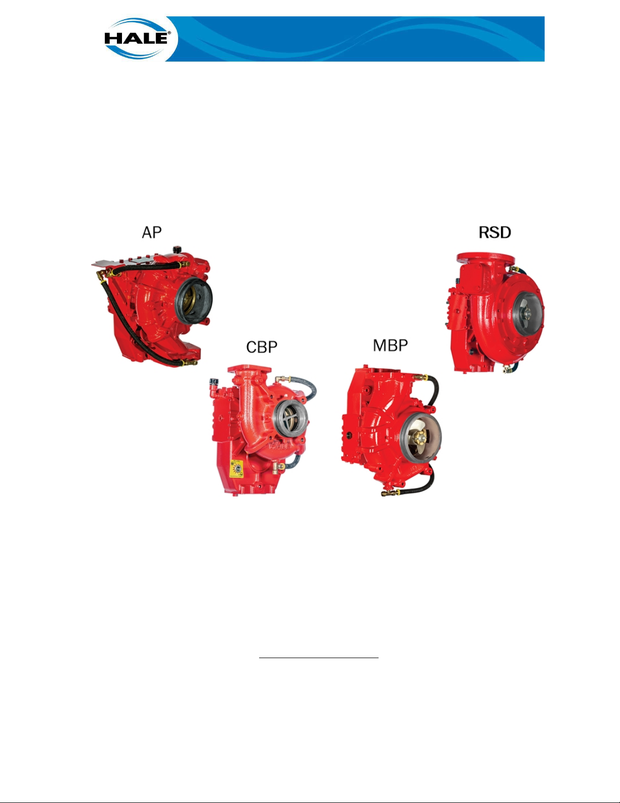
Hale Products currently produces four models of booster pumps:
• AP • MBP
• CBP • RSD
Unless otherwise indicated, these procedures will apply to all models of Hale booster pumps: Any
variations in operation or maintenance for the different models will be addressed within the context of this manual. The AP, CBP, and MBP booster pump maintenance technics are similar and
are therefore grouped in this manual. The RSD booster pump maintenance technics differ significantly and are presented separate from the AP, CBP, and MBP booster pumps.
Hale booster pumps are the favorite of fire fighters throughout the world. Booster pumps can be
used as initial attack pumps or as auxiliary pumps in conjunction with the apparatus main pump.
Covering a range of capacities from 20 gpm (75 Lpm) to 1500 gpm (5,678 Lpm), Hale booster
pumps offer the versatility, dependability, reliability, small size, and ease of operation so necessary for effective firefighting.
Hale booster pumps are of a compact size and lightweight design for easy mounting on the apparatus chassis. The pump coupled with the new aluminum gearbox allows the apparatus builder to
only supply the PTO and connecting shaft or direct engine mount a Flex series single stage
booster pump.
2.2. How To Use This Manual
This manual was developed for the purposes of FAST team and OEM support. This manual provides information and procedures to perform three levels of pump maintenance and impeller
renewal. The manual also provides information to be used to troubleshoot and R&R failed components based on the three levels of repair and impeller renew kits available from Hale Products
Inc. The repair/impeller renew kits support pump maintenance, repair, and rebuild.
This manual requires the use of the both the Hale Assembly drawings and the Parts Manual For
Hale Single Stage Booster Pumps (FSG–MNL–00185) for parts identification. Use the Parts
Manual to determine the drawing sheet (or sheets) required for reference. Then use the drawing(s) to locate the part and the item number associated with that part. The item number also
appears listed (in numerical order) in the parts table along with the part number, description, and
quantity for that item number.
The Introduction section is of interest to management for pump familiarization, visual recognition, pump identification documentation, and risk assessment information.
The Safety section is of interest to both management and maintainers as it provides precautions
for maintenance (including operation for maintenance purposes) and definitions of warnings,
cautions, and notes. This section also provides a summary of both PPE and a DANGER/ WARNING/CAUTION/NOTICE summary. The section provides a single point view of compiled hazards
and PPE in a condensed format. The appropriate DANGER, WARNING, CAUTION, or NOTICE and
PPE list also appears at each point of use throughout the manual.
7
The two Maintenance sections provide all aspects of maintaining the AP, CBP, MBP, and RSD
pumps, including sparing, preventive and corrective maintenance (which includes troubleshooting and remove and replace instructions). Notice that the use of this manual also requires
maintenance personnel to have received Hale training prior to using it. Use Hale Training Academy (Pumping And Maintenance) training (see paragraph 1.3, Training) and the two Maintenance
sections for all aspects of maintaining the pumps.
Within the two Maintenance sections, the troubleshooting provided utilizes SCR tables which
provide the list of known symptoms associated with a pump trouble/problem/failure. To use a
SCR table, locate the indicated SYMPTOM, verify the associated CAUSE (the maintainer must verify ALL the associated causes if multiple causes are listed) and then perform the associated
REMEDY (or remedies). The R&R procedures provide pump removal from the apparatus via two
separate methods: removing a pump as a complete assembly or removing only the pump portion
leaving the gearbox in the apparatus. Once removed the subsequent pump or gearbox repairs
are treated as bench procedures each covering a specific level (1, 2, 3, or renewal) of maintenance. Each level of maintenance requires the associated repair kit be utilized. Utilizing the associated repair kit ensures all the required components are available for replacement. Utilizing
the repair kits as intended prolongs pump performance and supports the manufacturer’s warranty.
Performing a procedure is NOT the ONLY key action in maintaining a pump, documentation of the
pumps Preventive Maintenance, R&R, and SYMPTOM/REMEDY history (including meaningful
tracking of when each issue occurred) is also key to maintaining each pump. A maintenance log
with meaningful entries will provide invaluable insight, time/money savings (in reduced down
time and shorted troubleshooting time), and cost savings over the life cycle of each pump.
2.3. Pump Specifications And Numbering
Hales policy is one of continuous development. Hale therefore reserves the right to amend specifications without notice or obligation. Refer to Section 2.2, Pump Specifications And Numbering,
in the Hale OIM manual (FSG–MNL–00183) for serial number locations, model number definitions, and major pump features. Refer to the Hale Products website (www.haleproducts.com) for
detailed booster pump specifications. NOTE: Using your pumps serial number and the Hale website (or Customer Service) is the best way to ensure you receive/utilize the correct replacement
parts for your pump.
2.4. Principles Of Operation
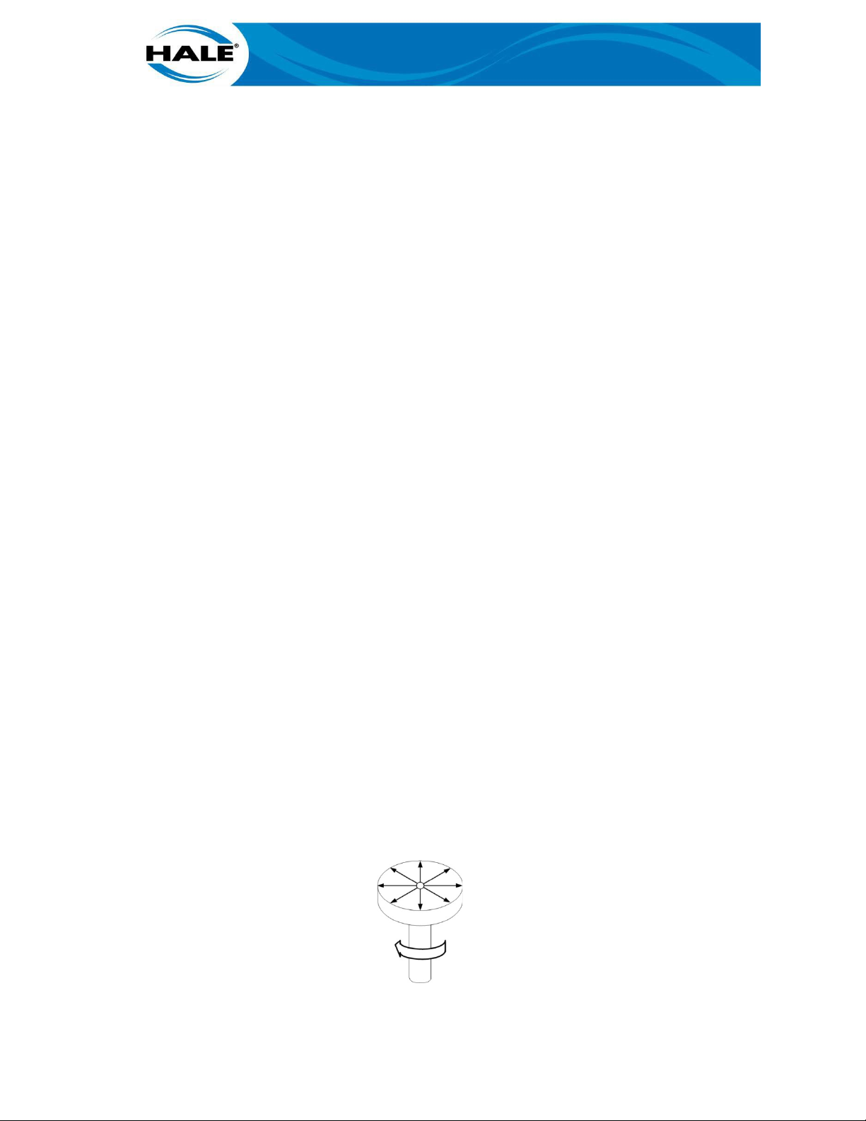
Hale booster pumps are centrifugal pumps that operate on the principle that centrifugal force is
created by a rapidly spinning disk. Figure 1 shows an amount of water has been placed at the
center of a disk. The disk is rotated and the water is thrown outward from the center to the edge
of the disk. The velocity at which the water travels from the center directly relates to the diameter
of the disk and the speed of rotation. When water is confined in a closed container (such as the
volute), the velocity is converted to pressure; pressure is therefore, dependent on the speed of
rotation.
8
Figure 1. Centrifugal Force From A Rotating Disk
There are three interrelated factors that regulate the performance of a centrifugal pump:
Speed (RPM):
If the speed of rotation increases with the flow held constant, the water pressure increases.
Pressure:
Pressure is usually expressed in psi or bar. If pressure changes and speed is constant, the flow
will change inversely (if pressure increases, flow decreases).
Flow:
Flow is usually expressed in gpm or Lpm that a pump can deliver when supplied from draft. If the
pressure is held constant, the flow will increase with an increase in the speed of rotation.
The centrifugal pump is preferred by the fire protection service due to its ability to fully utilize any
positive inlet pressure, reducing the strain on the pump.
For example, if the required discharge pressure is 120 psi (8 bar), and the inlet pressure is
45 psi (3 bar), the pump must only produce the difference in pressure of 75 psi (5 bar). This contributes to low engine and pump speeds which reduces wear on the pump. Another important
benefit is the centrifugal pump has basically only two moving parts; the impeller and the shaft.
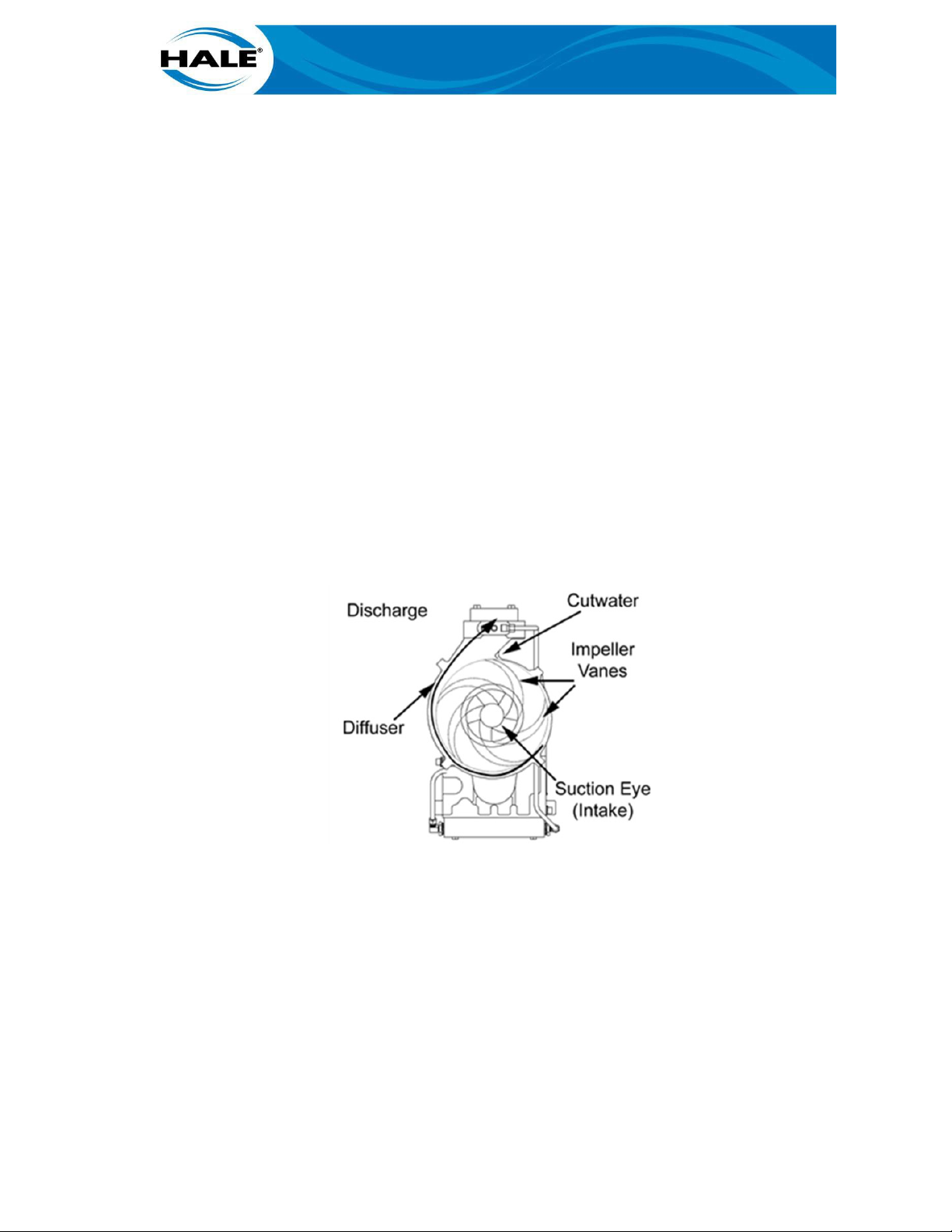
As shown on Figure 2, during operation water enters the suction eye of the impeller (intake). The
rotating impeller vanes develop discharge pressure and direct the water to the discharge opening. The cutwater is a wedge that divides the water between the volute (a single chamber diffuser) and the pump discharge.
Figure 2. Single Stage Water Flow
2.4.1 Explanation Of Terms
The following major terms are explained in sufficient detail to allow a maintainer to communicate
pumping issues or troubles with Hale Customer Service personnel. As a basic understanding of
the terms (and the principles associated with them) will assist operators (for both operations and
maintenance purposes) utilize common terminology and understand accepted principles when
communicating among each other.
2.4.1.1 Atmospheric Pressure (Static Air Pressure)
Air pressure is 14 pounds (AKA psi) at sea level. Pressure increases below sea level and decreases above sea level due to the increased or decreased volume of air pushing down at that
height. In addition to the amount of air, weather also effects air pressure. Air in a high pressure
9
area compresses and warms as it descends. The warming inhibits the formation of clouds,
meaning the sky is normally sunny in high pressure areas. But haze and fog still might form. Just
the opposite occurs within an area of low atmospheric pressure. Atmospheric pressure affects a
pumps ability to pump from draft. Higher pressures will increase a pumps performance, while
lower pressures can cause a noticeable decrease in lift.
2.4.1.2 Cavitation
The definition of cavitation is the formation of empty cavities (low-pressure bubbles) in a liquid
being moved by means of mechanical force (such as the rotation of an impeller) which is then
followed by their immediate and sudden implosion. The resulting forces can be as damaging as
striking the metal with a hammer. Cavitation within a pump may sound as if the pump were filled
with gravel or being struck with a hammer. See Section 3.5, Cavitation (Details), for more details.
2.4.1.3 Dead Heading
Operating a pump without any discharge is known as dead heading. Lack of flow causes temperatures to rise inside the pump.
2.4.1.4 Impeller And Clearance Rings
The impeller is the primary working part of a centrifugal pump. The impeller moves the water. An
impeller consists of two discs surrounding curved vanes. The vanes force water to rotate within
the discs resulting in the water being thrown outward at high velocity. The water from the impeller discharges into the volute, converting the high velocity energy into pressure.
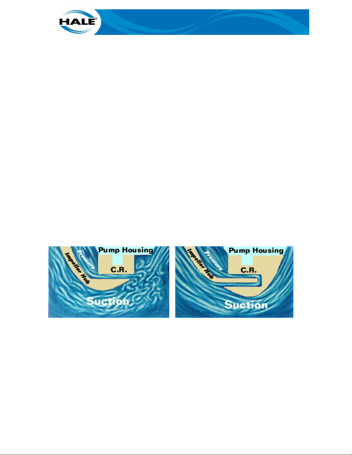
The clearance rings minimizes the amount of water that bypasses the discharge and returns to
the suction side of the impeller reducing pump performance (gpm). The wrap around clearance
ring reduces the bypass even more than the typical style ring (see Figure 3). Clearance rings are
ware items that protect the volute from experiencing the ware generated by the moving water
and especially the debris (sand, salt, etc.) when present.
Figure 3. Clearance Ring Water Flow
2.4.1.5 Priming Pump
An auxiliary pump attached to provide positive displacement of air out of the booster pump creating a vacuum which initially draws water into the pump. The type of priming pump used (by Hale)
for the AP, CBP, MBP, and RSD pumps is an electric motor driven rotary vane pump. Once the
main pump is primed and pumping, the priming pump is turned off.
2.4.1.6 Relief Valve
An automated valve with a control mechanism that maintains the pump pressure within 30 psi
when the pump discharge is gated (reduced) or closed (off). The valve maintains a set pressure
by diverting a portion of the pump discharge flow into the pump suction.
10
2.4.1.7 PM Relief Valve Control
The PM indicates a panel mounted hand-adjustable valve. When set to the desired pressure, the
relief valve will maintain the desired pump discharge pressure and limit a pressure increase to
no more than 30 psi (2 bar).
2.4.1.8 Volute
The increasing discharge path of the pump, its function is to collect the water from the impeller
and depending on its design can either increase pressure and decrease velocity or increase velocity and decrease pressure.
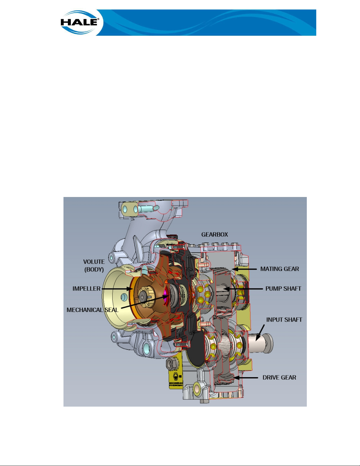
2.4.2 Standard Booster Pump Components
All Hale Flex Series single stage booster pumps (AKA the standard pump) consist of the following:
• Volute • Gearbox
• Impeller • Gears (Drive, Mating/Pump)
• Mechanical Seal • Shaft Assemblies (Input, Pump)
Figure 3 shows these standard parts of a Hale booster pump. These parts are briefly described in
the following paragraphs.
Figure 4. Parts Of The Hale Booster Pump
11
2.4.2.1 Volute
The Hale AP, CBP, and MBP single stage booster volutes (body) are a single-piece casting. Service of the impeller, clearance rings, and mechanical seal is accomplished by removing the volute from the assembled pump head and gearbox. The Hale RSD single stage booster volute is a
three-piece casting, with service of the impeller, clearance rings, and mechanical seal accomplished by removing ONLY the appropriate piece of the volute required to access the component
requiring service.
All volutes are constructed from fine grain cast iron. For areas where salt water is commonly
used, a bronze version of each booster pump is available.
The Hale Flex Series single stage booster pumps support multiple discharge port configurations.
Depending on the model, the pumps provide between 12 and 24 different configurations (including both rotations – ER or OER). Refer to the Parts Manual For Hale Single Stage Booster Pumps
(FSG–MNL–00185), Section 2,
charge Positions paragraphs) for a reference to the appropriate drawing and sheet number(s)
providing the views of the volute positions.
2.4.2.2 Impeller And Shaft Assembly
The impeller provides velocity to the water. The impeller is made of high quality bronze and is
mounted on a stainless steel shaft that is rotated by the gearbox. Water enters the rotating impeller at the intake (or eye). The vanes guide water from the intake to the discharge. Vanes curve
away from the direction of rotation so water moves toward the outer edge (see Figure 2). The
shrouds (discs) form the sides of the impeller and keep the water confined to increase acceleration and pressure. The back of the impeller houses the rotating portion of the mechanical seal.
Hale Booster Pump Illustrated Breakdowns, (Gearbox And Dis-
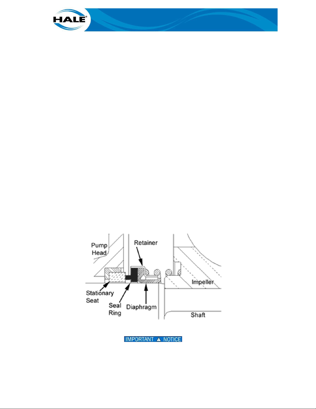
2.4.2.3 Mechanical Seal
The mechanical seal is common to all Hale booster pumps. Figure 4 shows a stationary seat is in
constant contact with a rotating seal ring to prevent leakage. The seal ring/diaphragm is specifically designed for high-temperature, low friction, self-adjusting, dependable operations.
Figure 5. Mechanical Seal
IF A PUMP IS OPERATED WITHOUT WATER, OR WITHOUT DISCHARGING WATER, IT
MAY OVERHEAT. FAILURE TO FLOW WATER MAY DAMAGE THE MECHANICAL SEAL OR
THE DRIVE MECHANISM.
12

2.4.2.4 Gearbox
The gearbox is cast aluminum and machine finished. The gearbox can be mounted in any one of
six positions. Refer to FSG–MNL–00185 (Parts Manual For Hale Single Stage Booster Pumps),
paragraph 2.1, (Gearbox Illustrated Breakdowns) for a reference to the appropriate drawing and
sheet number providing the views of the gearbox positions available.
Inside the gearbox a gear set transfers engine power from the input shaft, made of heat treated
nickel steel, to the pump shaft to turn the impeller at the appropriated speeds, which are determined by the gear ratio of the gear set selected. Hale offers a variety of pump gear ratios to accommodate a wide range of end-user and apparatus manufacturer requirements based on the
pump's intended use, horsepower and speed rating of the engine, or the torque rating of the
transmission PTO. Refer to FSG–MNL–00185 (Parts Manual For Hale Single Stage Booster
Pumps), paragraph 2.1, (Gearbox Illustrated Breakdowns) for a reference to the appropriate
drawing and sheet number providing the gear ratio listings available.
2.5. Pump Drives
The Hale Flex Series pumps support the common types of booster pump drives used on firefighting apparatus:
• The most common drive is the PTO mounted on the truck transmission or four-wheel drive
transfer case, which allows for pump and roll operation.
• Direct engine mounting via SAE#3 (or #4) flywheel housing.
Hale booster pumps are built to produce the volumes and pressures shown on their respective
performance curves and specifications (see paragraph 2.3, Pump Specifications And Numbering). However, the volumes and pressures safely obtainable are dependent on the torque capacity of the apparatus transmission or transfer case, power takeoff and the pump drive line. In most
cases, the torque rating of the PTO determines maximum pump performance.
The apparatus builder can provide various pump performance spots that will define the torque
limit of the PTO in terms of gpm and psi. When pumping continuously, care should be taken not
to overheat the PTO, transmission or transfer case.
Hale booster pumps are available for either engine rotation or opposite engine rotation PTO operation. Since some PTOs match engine rotation and some turn opposite of the engine rotation,
each pump model can be built to match the rotation of the PTO.
NOTE
Please refer to Hale Bulletin #886 and F–72 (Hale Torque Limit Chart) for further assistance in selecting the correct Flex series booster pump PTO.
Hale booster pumps are also available with an adapter that allows direct engine mount. Figure 5
shows the available flywheel housing (SAE #3 or #4) with the gearbox in the inverted configuration and the volute in the up configuration.
13
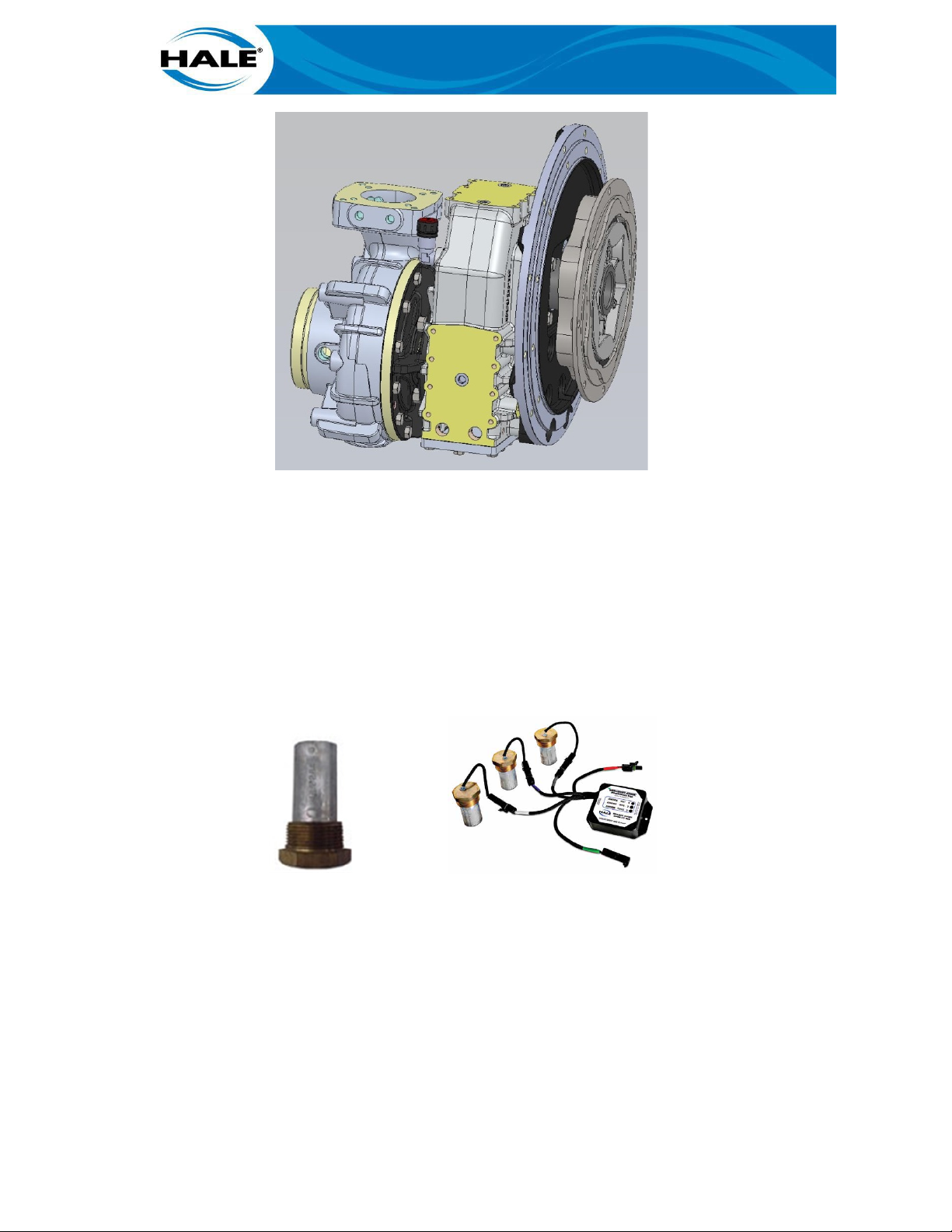
Figure 6. Direct Engine Mount
2.6. Optional Pump Components
In addition to the basic parts of Hale booster pumps described above, the following items are
available to enhance pump operation:
• Anodes
• TRVs
2.6.1 Anodes
The Hale anode system (Figure 6) helps prevent pump damage caused by galvanic corrosion.
Figure 7. Hale Anode
Galvanic action pits the pump and pump shaft material. The popularity of non-corrosive water
tanks and piping has increased this type of corrosion in today’s fire pumps. The Hale anode system is a sacrificial metal, which helps prevent corrosion. A Hale makes an anode that will fit on
any Hale truck mounted pump, regardless of age or model. The RSD uses Hale anodes designed
to be easily installed ONLY requiring four bolts and a gasket. Total time to install is just fifteen
minutes or less, yet it will provide years of protection for the pump. The anode kit is designed for
installation in the standard Hale 115 series flange opening located on the side of the RSD volute
(K port). On fabricated manifolds and similar applications, the installer is to provide 1-1/4-in NPT
openings and install anodes directly. It is recommended that one anode be installed on the suction side and one on the discharge side.
14

2.6.2 TRVs
Hale optional offers a thermal relief valve in two temperature ranges and with remote indication.
• TRV–120
• TRV–170
• TRV–L
The TRV is a thermal relief valve that acts as a thermostat and opens when the temperature of
the water in the pump exceeds 120 ℉ (TRV–120) or 170 ℉ (TRV–170) and resets (closes)
when the water cools. The RSD utilizes the standard Hale 115 series flange opening located on
the side of the volute (K port) and a flange adaptor to house the TRV. For all other Flex series
booster pumps the TRV must be installed on a fabricated manifold and similar application and
the installer is to provide 1-1/4-in NPT opening and install the TRV close to the volute discharge
port. The TRV discharge water should be directed to the ground or back to the booster tank, helping to keep the pump cool and avoiding premature wear and damage.
The TRV–L is a TRV (120 ℉ or 170 ℉) with the added feature of a remoted indicator (audible
and visual) panel to show when the TRV is open and flowing water. The indicator panel also has
an integral test switch.
15

3. MAINTENANCE OPERATING PROCEDURES
This section provides information and procedures for the operation of Hale booster pumps for
the purpose of performing maintenance. Maintenance operating procedures differ greatly from
typical operations. Typical operations are based on the pump being installed in a firefighting apparatus and include pumping from: an onboard tank, or a hydrant, or from draft. Operating procedures for maintenance purposes include pump performance verification, repair verification,
and troubleshooting and unless otherwise indicated, these instructions apply to all Hale booster
pumps.
THE PROCEDURES IN THIS SECTION PROVIDE ONLY GENERAL/MINIMAL INSTRUCTION. DO NOT REPLACE LOCAL PROCEDURES OR POLICIES OR RECOMMENDATIONS
AND PROCEDURES PROVIDED IN THE APPARATUS/TRUCK/UNIT MANUAL WITH
THESE PROCEDURES.
ALWAYS FOLLOW LOCAL GUIDELINES FROM THE AHJ AND THE APPARATUS MANUFACTURER.
ALWAYS FOLLOW PROPER OPERATING PROCEDURES. THE PUMP OPERATOR MUST
BE FAMILIAR WITH THE PUMP OPERATING INSTRUCTIONS AS WELL AS OTHER OPERATING GUIDELINES FOR THE APPARATUS AND ACCESSORIES.
A PRESSURE HAZARD MAY EXIST EVEN WHEN THE PUMP IS NOT RUNNING. PRIOR
TO REMOVING HOSES OR CAPS FROM PUMP CONNECTIONS, RELIEVE PRESSURE BY
OPENING DRAINS. BLEEDER VALVES SHOULD ALSO BE USED WHEN CONNECTING
TO AN INTAKE FROM A PRESSURIZED SOURCE.
DO NOT EXCEED OPERATING PRESSURE LIMITS OF PUMP, INSTALLED PLUMBING,
HOSE(S), OR EQUIPMENT IN USE.
OPERATORS, INSTALLERS, AND MAINTENANCE PERSONNEL MUST BE TRAINED AND
QUALIFIED FOR ALL THE ACTIVITIES THEY PERFORM.
FAILING TO REDUCE SYSTEM PRESSURE BEFORE SYSTEM SHUTDOWN OR FLUSHING COULD RESULT IN WATER HAMMERING.
IF IN 30 TO 45 SECONDS ONE OF THE FOLLOWING (BULLETS) DOES NOT OCCUR
STOP THE PUMP AND CHECK FOR AIR LEAKS OR A POSSIBLE PUMP TROUBLE.
• THE DISCHARGE GAUGE READING INCREASES
• THE INTAKE GAUGE READING FALLS BELOW ZERO
• THE PRIMING PUMP DISCHARGES WATER TO THE GROUND
CONTINUING TO RUN THE PRIMING PUMP MAY RESULT IN PUMP FAILURE OR DAMAGE.
Utilize the testing provided herein ONLY for the intended purpose. The Repair Verification Operations procedure (paragraph 3.1) is intended as the initial post repair test for a repaired booster
pump and the paragraphs description explains why. If the pump passes the Repair Verification
Operations procedure proceed with the Pumping From Draft Verification Operations procedure
(paragraph 3.4 on page 23). ALWAYS verify a repaired pumps drafting ability before returning the
pump to service.
17
The Vacuum Test (paragraph 3.2 on page 20) is intended as the initial check to determine if a
pump leaks. This test quickly and safely indicates if a leak exists however it typically ONLY indicates a leak is present and usually does NOT locate the leak (or leaks). If a pump fails the Vacuum Test utilize the Pressure Test (paragraph 3.3 on page 22) to locate the leak (or leaks).
3.1. Repair Verification Operations
Perform the following steps when a repair is completed to verify the pump is functional. This procedure is performed by pumping from a hydrant to ensure a clean, high quality water source and
to eliminate the risk of pump damage that could occur from an extended priming period which
could result from attempting to draft with an unverified pump.
NOTES
Refer to department procedures for setting wheel chocks and laying out suction and
discharge hoses.
All valves, drain cocks, and caps should be closed.
A. Prepare truck to pump.
Position truck for best hydrant hookup and discharge hose layout. 1.
Bring truck to a complete stop and come to an idle. (Never attempt to 2.
shift a moving truck from
Apply truck parking brake. 3.
Shift truck transmission into NEUTRAL. 4.
Engage pump PTO switch. 5.
Shift road transmission into proper gear (usually DRIVE). 6.
Check the indicator lights to see if pump is in gear, check speedometer, 7.
and listen as pump goes in gear.
Momentarily press accelerator to ensure shift is complete. 8.
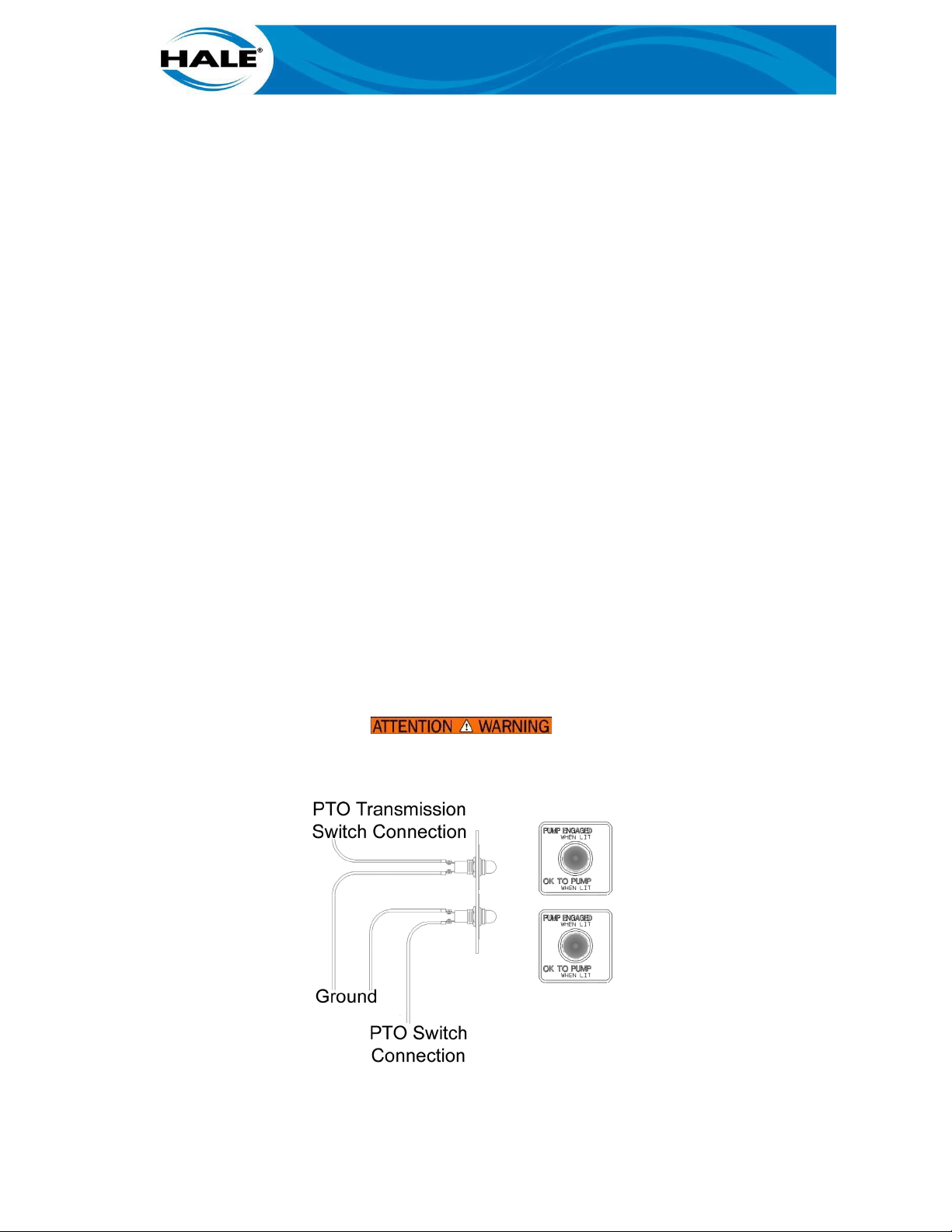
DO NOT LEAVE THE CAB OR ATTEMPT TO PUMP UNTIL ALL OK TO PUMP INDICATORS
IN THE CAB ARE ILLUMINATED. SEE FIGURE 7.
ROAD to PUMP.)
18
Figure 8. Driver Compartment Indicator Lights
ONLY after completing ALL previous steps, exit driving compartment. 9.
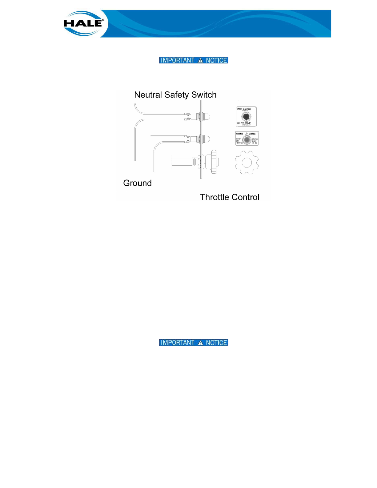
DO NOT OPEN THE THROTTLE UNLESS THE GREEN INDICATOR LIGHT IS ON.
SEE FIGURE 8.
Figure 9. Pump Operator Panel
Verify pump panel shift indicator light is on. 10.
Set wheel chocks. 11.
Complete all hose connections. 12.
B. Prepare pump to pump.
Open hydrant and bleeder valves (to bleed off air in suction hose). 1.
Open suction valve. 2.
If necessary to eliminate air pockets, prime pump. 3.
(For instructions, see paragraph 3.2, Pumping From Draft, on page 20.)
Slowly open appropriate discharge(s). 4.
Advance engine throttle gradually until master discharge gauge indicates 5.
desired pressure.
DO NOT ALLOW THE PRESSURE ON THE INTAKE GAUGE TO GO BELOW ZERO. PLACING A VACUUM ON THE WATER MAIN MAY RESULT IN SERIOUS DAMAGE TO OR FAILURE OF THE WATER MAIN.
NOTES
The master intake gauge reading must be maintained at 5 psi (0.3 bar), minimum. If
the gauge shows a vacuum the pump is attempting to draw more water than the hydrant can supply. When this occurs, reduce the pump flow to increase the pressure.
As the throttle is opened, the pressure gauge reading should increase with the engine speed. If the engine speed increases without an increase in pressure, the pump
is beginning to cavitate. Close the throttle slowly until the pressure begins to drop
and the engine returns to an idle.
19

Standard Tools
Special Tools
Consumables
If pump overheats, perform appropriate following step. 6.
a) If pump is NOT equipped with a Hale TRV valve, open appropriate valve(s) (usually
tank fill or gutter line) to provide a bypass line.
b) If pump is furnished with a Hale TRV valve, open valve to booster tank (both suc-
tion and discharge sides) to circulate water (and/or fill water tank).
C. Verify pump is operating correctly by checking ALL gauge readings.
D. Begin shutdown.
Gradually reduce throttle and pump pressure until engine is at idle speed. 1.
Close discharge(s). 2.
Ensure tank is full of water. 3.
If opened, close bypass line valve(s) or TRV. 4.
Close suction valve. 5.
Place transmission in NEUTRAL. 6.
Disengage PTO. 7.
Close hydrant. 8.
E. Disconnect all hose connections and stow hoses.
F. Make all appropriate Maintenance Log entries.
G. Perform Pumping From Draft Verification Operations procedure (see para-
graph 3.4 on page 23).
3.2. Vacuum Test
Refer to Table 1 for a list of tools and/or consumables required for this procedure.
Table 1. Vacuum Test Tools And Consumables List
PPE
(Eye, Hand, and Ear Protection)
Blanking Cap(s) (As Required)
Tachometer
30 inHg Vacuum Gauge (or Manometer)
(Use ONLY a High Quality Calibrated Gauge/
Manometer)
Shop Rag(s) (As Required)
This test is intended to ONLY test the booster pump for leaks. A known good vacuum pump is
preferred for this test. However, if the apparatus has a primer pump, that primer can be used for
this test to verify both are leak free and the primer does NOT exhibit excessive wear or damage.
If the apparatus associated primer does NOT reach a vacuum of 22 (± 2) inHg (0.745 bar) but
holds a lower vacuum, a fault in the primer is indicated. Perform the following steps to Vacuum
Test a pump.
A. Place blanking cap(s) on pump inlet(s).
B. If no apparatus primer is present, connect a known good primer or vacuum
C. Close discharge valve(s) or place blanking cap(s) on pump outlet(s).
20
pump (along with a vacuum/compound gauge) to highest discharge port.

DO NOT RUN THE PRIMER FOR MORE THAN 45 SECONDS IF PRIME IS NOT
ACHIEVED. IF PRIME IS NOT ACHIEVED IN 45 SECONDS, STOP AND LOOK FOR CAUSES (AIR LEAKS OR BLOCKED SUCTION HOSE). RUNNING THE PRIMER FOR LONGER
PERIODS WITHOUT ACHIEVING PRIME MAY RESULT IN PRIMER AND/OR PUMP DAMAGE OR FAILURE.
NOTE
NFPA 1901 recommends: The time required to prime the pump if the rated capacity
is 1250 gpm or less shall not exceed 30 seconds. If the rated capacity is 1500 gpm
or more, the time to prime the pump shall not exceed 45 seconds.
D. Run primer pump and observe vacuum/compound needle as follows.
When 22 (± 2) inHg (-0.745 bar) of vacuum is obtained, stop pri-1.
mer/vacuum pump.
Pump under test shall maintain this vacuum. 2.
a) For at least 15 seconds.
b) And NOT drop more than 2 inHg (0.07 bar) in 1 minute.
c) And NOT drop more than 10 inHg (0.33 bar) in 5 minutes.
NOTES
If pump does NOT hold at least 22 (± 2) inHg (0.745 bar) of vacuum with the blanking caps in position, a leak is present in the apparatus/pump, and a pressure test
must be performed to trace the leak.
If the apparatus/pump can NOT reach a vacuum of 22 (± 2) inHg (0.745 bar) but
holds a lower vacuum, a fault in the primer pump is indicated. NOT reaching an acceptable vacuum AND NOT being able to locate a leak may indicate excessive wear in
the primer.
Even though the apparatus meets the NFPA minimum leakage requirement, a small
air leak in the wrong spot will reduce pump performance. Preferably, your performance should exceed the minimum set by NFPA. In reality, the 10 inHg. in 5 minutes
was allotted for pump shaft packing adjustment and not for plumbing or valve leaks.
Since all Hale two stage booster pumps utilize a mechanical seal, the vacuum drop
over a 5-minute period should be insignificant.
E. If pump passes Vacuum Test.
Remove all test plates and primer. 1.
Complete maintenance log entry(ies). 2.
Return booster pump to service. 3.
F. If pump fails Vacuum Test perform Pressure Test.
(See paragraph 3.3, on page 22.)
21

Standard Tools
Special Tools
Consumables
3.3. Pressure Test
This test is to be carried out ONLY if the pump will not hold a vacuum with blanking cap(s) in position, and is intended to trace the leak(s) responsible for the loss of vacuum. This test is conducted without the pump running. Refer to Table 2 for a list of tools and/or consumables required for this procedure.
Table 2. Pressure Test Tools And Consumables List
PPE (Eye and Hand Protection) None Shop Rag(s) (As Required)
Pressurized Water Source
(50 to 100 psi)
Perform the following steps to pressure test a pump.
A. Place blanking cap(s) on pump inlet(s) and outlet(s).
B. Attach pressurized water source. (Can be attached via a blanking plate or
pump plug.)
C. Apply a water pressure of 50 – 100 psi (3.5 – 7.0 bar or 350 – 700 kPa) to
pump.
D. Check for leaks.
Visually inspect all drain/relief valves for water leakage. 1.
Visually inspect all external fittings/hoses on pump for water leakage. 2.
Visually inspect all external areas/surfaces of pump for water leakage. 3.
Visually inspect all external areas/surfaces of primer assembly for water 4.
leakage.
a) If leakage is found, replace the primer seals and O-rings. Refer to para-
graph C.3.3.3, ESP Primer Maintenance, in APPENDIX C.
b) If leakage persists, replace primer assembly.
If the pump will not achieve 22 (± 2) inHg (–0.745 bar or –74.5 kPa) of vacuum, and will not
hold what it does achieve, there is a leak. It may possibly be a fault in the primer (if apparatus is
so equipped) or the pump shaft seals.
If the apparatus priming pump was used for the Vacuum Test (or was attached to the pump during pressure testing) and no external leaks are apparent, first check the primer (ONLY if the apparatus is so equipped and the primer was attached during testing). Primer points to check are:
• Low charge on or batteries not of sufficient size.
• Electrical connectors on cable dirty or bad ground.
• Primer vanes worn.
• Priming valve not fully opening (operator error).
If a fault in the primer is NOT indicated check the pump shaft seals and the gearbox cooling tube.
Pump shaft seal and cooling tube points to check are:
• Water in the gear oil.
• Gear oil in the discharge or drain ports.
Complete all associated maintenance log entries.
22

3.4. Pumping From Draft Verification Operations
This test is ONLY conducted to verify a pump can now pump from draft when the fault repaired
prevented the failed pump from pumping from draft. Perform the following test ONLY when required to verify a pump repair has corrected a failure to pump from draft (lakes, ponds, streams
and other non-pressurized water supplies). This test is intended to be conducted under controlled conditions and NOT from a randomly available/selected water source.
NOTE
This test is intended to be conducted using a known lift under controlled conditions.
The pump can ONLY draw 100% of its rated capacity with less than a 10 ft vertical
lift. As the lift increases to above 10 ft, the pump capacity will be reduced and a conclusive test can NOT be conducted.
A. Prepare truck to pump from draft.
Position apparatus at test pit or other predetermined testing water 1.
source.
Bring truck to a complete stop. 2.
Apply truck parking brake. 3.
Shift truck transmission into NEUTRAL. 4.
Engage pump PTO. 5.
Shift road transmission into proper gear (usually DRIVE). 6.
Check indicator lights to see if pump is in gear, check speedometer, and 7.
listen as pump goes in gear.
Momentarily press accelerator to ensure shift is complete. 8.
DO NOT LEAVE THE CAB OR ATTEMPT TO PUMP UNTIL ALL OK TO PUMP LIGHTS IN
THE CAB ARE ILLUMINATED. SEE FIGURE 7.
ONLY after completing ALL previous steps, exit driving compartment. 9.
DO NOT OPEN THE THROTTLE UNLESS THE GREEN INDICATOR LIGHT IS ON.
SEE FIGURE 8. FAILURE TO WAIT FOR THE ILLUMINATED GREEN INDICATOR MAY RESULT IN EQUIPMENT DAMAGE OR FAILURE.
Verify pump panel shift indicator light is on. 10.
Open Tank-to-Pump valve. (Prevent pump from running dry as quickly as 11.
possible.)
Set wheel chocks. 12.
Complete all hose connections and close all discharges. 13.
a) Ensure intake hose is free of humps and sharp bends and no part of hose is high-
er than pump intake inlet. (Air pockets in the intake hose may cause loss of prime
or erratic pump action, and may reduce pump capacity.)
b) Ensure all intake connections are tight and all discharge valves are closed.
23

B. Prime pump.
RUNNING THE ENGINE AT SPEEDS HIGHER THAN 1200 RPM DURING PRIMING IS
NOT RECOMMENDED SINCE IT WILL NOT IMPROVE PRIMING OPERATION AND MAY
CAUSE DAMAGE TO THE PUMP.
IF IN 30 TO 45 SECONDS ONE OF THE FOLLOWING (BULLETS) DOES NOT OCCUR
STOP THE PUMP AND CHECK FOR AIR LEAKS OR A POSSIBLE PUMP TROUBLE.
• THE DISCHARGE GAUGE READING INCREASES
• THE INTAKE GAUGE READING FALLS BELOW ZERO
• THE PRIMING PUMP DISCHARGES WATER TO THE GROUND
CONTINUING TO RUN THE PRIMING PUMP MAY RESULT IN PUMP FAILURE OR DAMAGE.
Immerse intake strainer at least two feet below water surface to prevent 1.
pump from drawing air. (If whirlpools form above intake strainer the
strainer is too close to the surface of the water.)
Make sure intake strainer is far enough from the bottom to prevent sand, 2.
gravel and other foreign matter from being drawn into the pump.
NOTE
The pump is primed when the intake indication reading falls below zero, and the discharge pressure starts to increase. Water may also be heard discharging to the
ground.
If apparatus is equipped with a priming pump, activate priming pump. 3.
(Pull control handle located on pump panel.) Otherwise, slowly open appropriate discharge(s) and advance engine throttle gradually until master
discharge gauge indicates desired pressure.
Monitor intake and discharge master gauges. 4.
NOTE
As the throttle is opened, increase the pressure gauge reading with engine speed. If
the engine speed increases without an increase in pressure, the pump is nearing
cavitation.
C. Verify pump performance.
Set automatic control/relief valve per department policy. If no depart-1.
ment policy exists, refer to paragraph 3.6, Relief Valve Procedures, on
page 30.
If pump overheats, perform appropriate following step. 2.
24
a) If pump is NOT equipped with a Hale TRV valve, open appropriate valve(s) (usually
tank fill or gutter line) to provide bypass line.
b) If pump is furnished with a Hale TRV valve, open valve to booster tank (both suc-
tion and discharge sides) to circulate water (and/or fill water tank).
c) Verify pump is operating correctly by checking ALL gauge readings.

Water Temp
° F (° C)
Lift Loss In
Hd Ft (Hd M)
Water Temp
° F (° C)
Lift Loss In
Hd Ft (Hd M)
Water Temp
° F (° C)
Lift Loss In
Hd Ft (Head M)
D. Begin shutdown.
Reduce engine speed to idle. 1.
Close discharge valves. 2.
If opened, close bypass line valve(s) or TRV. 3.
Close suction valve. 4.
Place transmission in NEUTRAL. 5.
Disengage PTO. 6.
E. Disconnect all hose connections and stow hoses and strainers.
F. Make all appropriate Maintenance Log entries.
G. Return pump/apparatus to service.
3.4.1 Draft Limiting Factors
The effect of raised water temperatures when pumping from a positive pressure source (hydrant)
is negligible on fire pump performance. But when pumping from draft, elevated water temperature does have a limiting effect. Water temperatures above 90° F (32° C) will cause a noticeable
decrease in lift when drafting. (See Table 3 for additional losses beyond NFPA rating baseline.)
Another factor that can limit lift is barometric pressures below 29 inHg. It is important to be
aware of environmental conditions when drafting.
Table 3. Additional Losses Beyond NFPA Rating Baseline
60 (16) NFPA Baseline 80 (27) 0.6 (0.18) 100 (38) 1.7 (0.52)
70 (21) 0.3 (0.09) 90 (32) 1.1 (0.34) 110 (43) 2.5 (0.76)
25

3.5. Cavitation (Details)
Cavitation (see definition – paragraph 2.4.1.2 on page 10) can occur while pumping from draft,
in relay, or from a hydrant. The operator must be aware of the warning signs and correct the situation, or serious damage to the pump and impeller will occur. Figure 9 shows the results of cavitation.
Figure 10. Results Of Cavitation
Cavitation can damage the impeller and other sensitive components, impair pump performance,
and reduce flow capacity. The damage done during any one period of cavitation is not great, but
the effects are cumulative. Implosions occurring during cavitation break away or erode tiny pieces of metal from the internal parts and the pump casing. When enough metal has been chipped
away, the impeller becomes unbalanced causing a strain and vibration on bearings, bushings
and shafts.
The way to eliminate cavitation is to increase the flow to the pump, decrease the amount of water being discharged from the pump, or reduce the pressure in the pump by decreasing engine
speed.
3.5.1 Process Of Cavitation
Cavitation occurs when a centrifugal pump is attempting to discharge more water than it is receiving. It is often referred to as the pump running away from the supply.
A. When increased discharge demand exceeds the intake, bubbles form in the
low pressure region (eye) of the impeller. See Figure 10.
26

Figure 11. Low Pressure Regions
B. The pressure of the water in the pump drops as it flows from the suction
flange through the suction nozzle and into the impeller.
C. As flow from the pump increases, the vacuum at the impeller increases. As
the vacuum increases, the boiling point of water in that vacuum decreases
until it reaches a point near the impeller eye where it boils and vaporizes.
D. Once the vapor pockets, or bubbles, enter the impeller, the process begins to
reverse itself. As the vapor reaches the discharge side of the pump, it is subjected to a high positive pressure and condenses back to a liquid.
E. The sudden change from vapor to liquid generates a shock effect that dam-
ages the impeller and pump housing. Usually there are thousands of tiny vapor pockets (bubbles) rather than a few large ones. It is the collapsing (or implosion) of these bubbles that causes the characteristic sound of cavitation
that has been described as rocks tumbling in the pump.
3.5.2 Warning Signs Of Cavitation
As a pump approaches cavitation, certain warning signs appear on the gauges that monitor the
suction and discharge pressures. These signs are discussed in the following subparagraphs.
3.5.2.1 Discharge Pressure
In a properly functioning pump, an increase in RPM will increase the discharge pressure and volume. An increase in engine RPM that does not cause an increase in the pump discharge pressure, is the most reliable indication that a pump is approaching cavitation.
3.5.2.2 Vacuum Compound Gauge
The operator should not depend entirely on the vacuum (compound) gauge to indicate when a
pump is nearing cavitation: The vacuum gauge is usually tapped into the intake chamber several
inches away from the leading edge of the impeller eye where the greatest amount of vacuum occurs. The vacuum gauge does not take into account ambient temperature nor atmospheric pressure and is not accurate near zero on the vacuum scale.
3.5.3 How To Prevent Cavitation
Monitoring current operating conditions, knowing the capabilities of the equipment, and regular
inspection are the best protection against cavitation.
27

Hose Diameter
In (mm)
3
(76)
4
(102)
4.5
(114)
5
(127)
6
(152)
Dual 6
(Dual 152)
Flow
gpm (Lpm)
Lift Loss In
Head Ft (Head M)
When pumping from a hydrant, a soft sleeve has an advantage over a hard sleeve because it will
partially collapse providing an immediate indication to the operator that cavitation is imminent. A
hard sleeve indicates problems only at the intake gauge which is not the best or most reliable
indicator.
3.5.3.1 General Considerations
Consider the following to generally avoid conditions that lend themselves to cavitation.
• Regularly inspect discharge and suction hoses to check for air leaks as these can also cause
cavitation.
• Consider the size of the suction hose: Table 4 shows the NFPA pre-selected hose sizes for
each pump rating capacity. Using the appropriate-sized hose will minimize the occurrence of
cavitation.
Table 4. Hose Sizes For Pump Rating Capacity
250 (946) 5.2 (19.7)
350 (1325) 2.5 (9.5)
500 (1893) 5.0 (19.0) 3.6(51.5)
750 (2839) 11.4(43.0) 8.0 (30.0) 4.7 (17.8) 1.9 (7.2)
1000 (3785) 14.5 (55.0) 8.5 (32.0) 3.4 (12.9)
1250 (4732) 13.0 (49.0) 5.2 (19.6)
1500 (5678) 7.6 (28.7) 1.9 (7.2)
1750 (6625) 10.4 (39.4) 2.6 (9.8)
2000 (7571) 3.4 (12.9)
2500 (9464) 5.2 (19.6)
• Consider the piping within the truck: Further suction losses may result from additional suc-
tion piping added to the fire pump during assembly by the manufacturer.
• Follow the maintenance and inspection procedures.
• Cavitation can occur with large nozzle tips. Solve this problem by reducing flow.
• Cavitation can also occur when air enters the pump. The pump may be primed, however, air
leaks can cause rough operation and an increase of engine speed without an in- crease in
pressure or flow. If an air leak is suspected, discontinue pumping and refer to Section IV.
28

Barometric Reading inHg (mb)
Lift Loss In Head Ft (Head M)
Elevation Ft (M)
Lift Loss In Head Ft (Head M)
3.5.3.2 During Operations
During operations, additionally consider the following to further avoid conditions that lend themselves to cavitation. Being aware of the pumping environment can contribute greatly to avoiding
cavitation. Use Table 5 and Table 6 to help predict lift losses when operations dictate pumping
from draft.
• Do not increase the pump speed beyond the speed at which the pressure ceases to rise.
• Monitor the water temperature. NFPA standards set a baseline of 60° F (16° C). Table 3 il-
lustrates the amount of lift loss as temperatures rise. If there is a marked loss of suction capacity, the pump may be near cavitation.
NOTE
When water reaches 90° F (32° C), the operator is likely to notice a marked decrease in lift.
• Monitor barometric pressure. NFPA standards set a baseline of 29.9 inHg. See Table 5.
Table 5. Lift Loss From Barometric Pressure
29.9 (1012.53) NFPA Baselines
29.7 (1005.76) 0.2 (0.06)
29.5 (999.00) 0.5 (0.15)
29.3 (992.21) 0.7 (0.21)
29.1 (985.44) 0.9 (0.27)
28.9 (978.67) 1.1 (0.33)
28.7 (971.89) 1.4 (0.43)
• Know your elevation (especially in mountainous regions). NFPA standards set a baseline of
2,000 feet MSL. See Table 6.
NOTE
Location: The higher the elevation (height above sea level), the lower the atmospheric pressure and less lift. See Table 6.
Table 6. Lift Loss From Elevation
2,000 (609) NFPA Baseline
3,000 (914) 1.1 (0.33)
4,000 (1219) 2.2 (0.67)
5,000 (1524) 3.3 (1.00)
29

Elevation Ft (M)
Lift Loss In Head Ft (Head M)
Table 6. Lift Loss From Elevation – CONTINUED
6,000 (1828) 4.4 (1.34)
7,000 (2133) 5.5 (1.67)
8,000 (2438) 6.6 (2.01)
9,000 (2743) 7.7 (2.35)
10,000 (3048) 8.8 (2.68)
• Open the throttle gradually and, if equipped, watch the pressure gauge and the tachometer.
An increase in engine RPM without a corresponding increase in pressure indicates cavitation.
• Use a hard suction hose when pumping from draft and soft suction hose when pumping from
hydrant.
3.6. Post Operation Procedure
Perform the following steps at the end of all operations.
A. Return engine to idle.
B. Slowly close all valves.
C. Place transmission into neutral or park.
D. Drain pump (especially important in freezing weather):
Open discharge valves, remove suction tube caps, and discharge valve 1.
caps.
Open volute drain cocks or Hale multiple drain valve. If a multiple drain 2.
valve is used, all pump drain lines should be connected to this valve.
After pump is completely drained, replace all caps and close all valves. 3.
E. If any of the following was used, sea water, dirty water, alkaline water or foam
solution; flush pump with clean water.
F. Remove wheel chocks only when preparing to leave scene.
G. Fill out pump run log, indicating total pumping time and total out-of-station
time.
H. Report all pump, vehicle, and equipment malfunctions and irregularities to
proper authority.
I. Know and follow all local procedures.
30
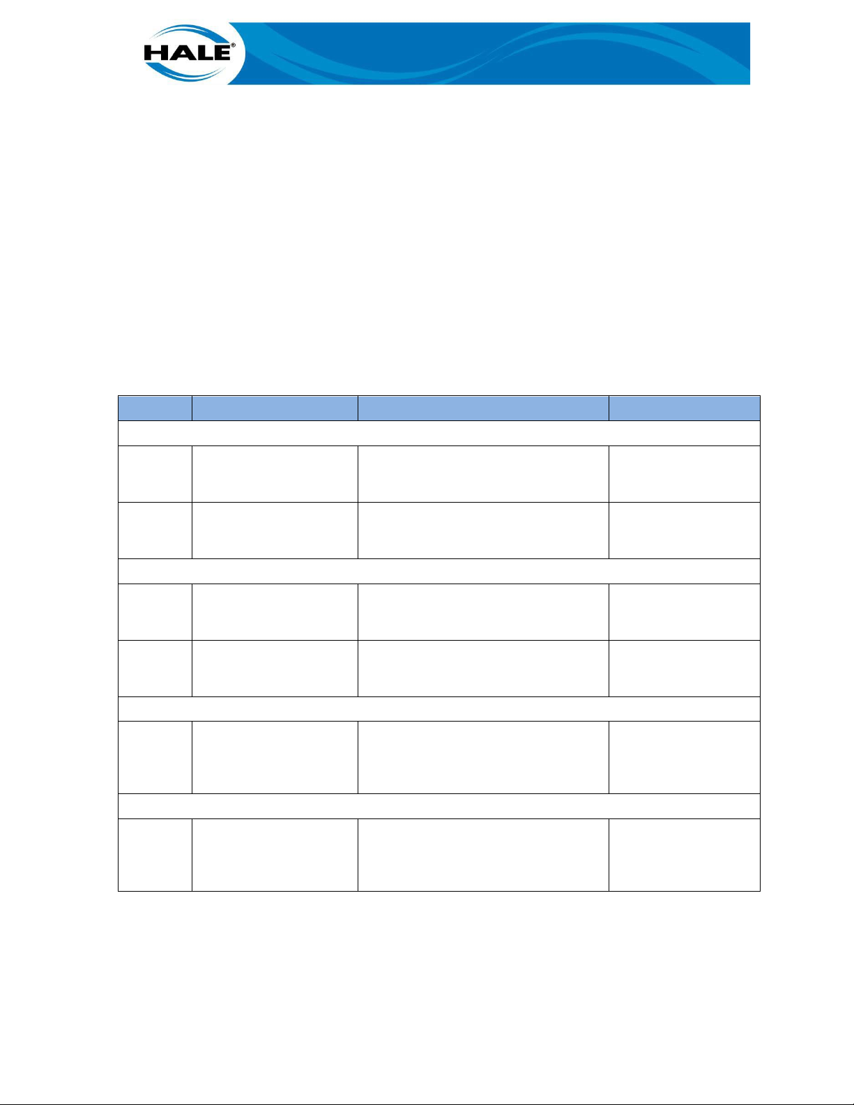
Interval
Check/Test
Action Required
Item(s) Required
After Each Use
Quarterly (Every 3 Months)
Annually (Every 12 Months)
Triennium (Every 36 Months)
4. PREVENTIVE MAINTENANCE
Regular preventive maintenance assures continued dependable operation. This section provides
recommended actions to be completed for both the booster pump and the ancillary equipment.
The pump preventive maintenance actions listed are scheduled to be completed after each use
and on a weekly, quarterly and annually basis.
4.1. Preventive Maintenance Plan And Schedule
Hale Products recommends the preventive maintenance and inspections listed in Table 7 be performed as scheduled. The booster pump requires very little care and maintenance, however, the
preventive maintenance and inspections required are important. The booster pumps do NOT require any daily, weekly, or monthly preventive maintenance. The listed preventive maintenance,
inspections and checks are required to ensure proper and economical operation and to minimize
corrective maintenance. Table 7 lists the projected preventive maintenance on a per use, quarterly, annual, and triennium basis.
Table 7. Recommended Preventive Maintenance – Pump
Flush if Contaminated Flush pump thoroughly with clean water
(See paragraph 4.4.1, Flush After Each
Use)
Leakage Checks Check for water or oil leaks (wipe off
road dirt and debris) (See paragraph
4.4.2, Leakage Checks)
Oil Level Check Check gearbox oil level using sight glass
(See paragraph 4.4.3.1, Check Gearbox
Oil Level)
Perform Vacuum Check Use installed primer to pull vacuum on
pump and valves (See 4.4.3.2, Perform
Vacuum Test)
Perform NFPA 1911 Per-
formance Level Test
Oil Change Drain oil from gearbox and refill with
Check the pump (according to the rating
in Table 9 at each capacity and compare the results to when the pump was
first placed in service.
new oil
(See paragraph 4.4.6.1, Gearbox Fluid
Change)
Supply of clean water
Shop Rags
None
None
Supply of clean water
1.25 qt Full Synthetic
Additionally, Hale Products recommends the preventive maintenance and inspections listed in
Table 8 also be performed as scheduled. Hale and OEM ancillary equipment preventive maintenance tasks take little time to accomplish and consist of leak testing, operational checks, lubrication and cleaning. The listed preventive maintenance, inspections and operational checks are
required to ensure proper and economical operation and to minimize corrective maintenance.
31

Interval
Check/Test
Action Required
Item(s) Required
Weekly
Table 8 lists the projected preventive maintenance on a weekly, monthly, quarterly, and annual
basis.
Table 8. Recommended Preventive Maintenance – Ancillary Equipment
Test Relief Valve System Operate the relief valve system to verify
it is functioning properly.
Test Pump Shift Warning
Indicator
Check Valves Verify each valve operates easily and
Check And Clean Intake
Strainers
Check Hydraulic Motor If the pump is powered by a hydraulic
Check All Gauges Check that gauges that are repeated (in
Check Pump Controls Check the pump drive controls to verify
Engage the pump and verify the indicator lights on the control panel function
properly and agree with the indicators
in the cab.
closes completely. Inspect all valve
linkages for lubricant and function.
Remove strainers. Clean strainers. Inspect strainers for any damage.
motor, check the motor for function,
filters, and fluid level. Inspect drive for
wear. Check drive for proper operation.
the cab or another panel), agree with
the gauge on the operator's panel.
Check that all gauges read within 10%
of a calibrated test gauge.
the pump can be engaged. Verify all
indicator lights work properly.
PM valve control &
onboard water
Wheel chocks
None
Supply of clean water
Shop rags
Calibrated test gauges
Onboard water
Inspect Water And Foam
Tanks
Check Roof And Bumper
Turrets
Check Auxiliary Fire Sup-
pression Equipment
32
Visually inspect water and foam tanks
for proper level, gauge readings, and
debris. If debris is present, flush tank to
protect the pump from dirty water or
foam concentrate contamination.
Verify all turrets function properly, and
no leaks are present.
Visually inspect all piping and valves on
the pump and auxiliary equipment for
corrosion or damage.
Supply of clean water
Supply of clean water
None

Table 8 Recommended Preventive Maintenance – CONTINUED
Interval
Check/Test
Action Required
Item(s) Required
Monthly
Quarterly (Every 3 Months)
Annually (Every 12 Months)
Test Priming System Dry Vacuum Test per NFPA 1901 or
NFPA 1911
Check Drive Line Bolts Inspect for missing bolts. Torque all
drive line bolts. Inspect all drive line
bolts are Grade 8 or stronger.
Lubricate Relief Valve Inspect and lubricate all relief valve
operators.
Check Drain Lines Check individual drain lines going to the
multi-drain to ensure drains empty
(providing protection from freezing).
Test Tank To Pump Flow
Rate
Compare flow rate measured to NFPA
minimum (or designed rate of pump). If
flow rate is lower, a problem exists in
the tank to pump line. The minimum
flow rate should be continuously discharged until 80% of the tank is discharged.
Inlet and outlet caps
Vacuum gauge
(or manometer)
5 min timer
Torque wrench
Brush
Grease
None
Supply of clean water
Clean ESP Primer Disassemble ESP primer and clean
mineral deposits. See paragraph
C.3.3.3, Clean ESP Primer.
Lime Scale Remover &
Soft Bristle Brush
4.2. Maintenance Log
As a minimum, use this form to record all maintenance actions: cleanings, checks, faults, tests,
parts replaced, and tear downs/major overhauls. An accurate maintenance log can provide key
insights when pump problems arise; preventing extended down times, and shorten troubleshooting.
Full page Log sheets are provided in APPENDIX D, Operator Maintenance Log, for your convenience. Always keep at least one original (unused) sheet in this manual for copying purposes. The
remaining pages may be used to start the LOG.
A sample of the Log (with only a single row of data/entry cells) is provided below. The recommended data/entries are explained in detail in the text that follows the sample.
PUMP SERIAL NUMBER:
33

DATE
HOURS
RUN
MAINTENANCE/
PROBLEM
PART(S)
USED
REASON
REPLACED
INITIALS
Use this Log to record all maintenance actions and problems (faults, part replacements, tear
downs, and major overhauls – as a minimum). Please contact Customer Services at Hale Products Inc. prior to any proposed return of either a single part, or a complete assembly.
To make the most effective Log always fill in every Log cell for each entry as follows as a minimum.
Enter the DATE: chronology, this is important as loose pages may get out-of-order.
Enter the HOURS RUN: the accumulated hour of run time is important for adjusting the recommended maintenance intervals. These intervals should be adjusted (especially if a shorter interval is suggested by the data) since an individual pumps operating environment can vary widely.
Clean verses dirty water sources, ambient operating temperature for the geographical location or
mounting location, and other key factors should be considered for planned/scheduled maintenance purposes.
Enter the MAINTENANCE/PROBLEM: enter ALL maintenance actions (especially those listed in
Table 7 although items listed in Table 8 should NOT be ignored or excluded) and problems the
pump encounters. The more complete the Log, the more time saved if/when troubleshooting is
required and good (or bad) maintenance practices become highly visible. A PUMPS HISTORY CAN
BE INVALUABLE TO A TRAINED TECHNICIAN.
Enter the PART(S) USED: enter ALL parts replaced. It is important to list not only the assemblies
and components replaced but always include the little things: hoses, connectors, fasteners,
seals, thread lock, etc. The replacement of the little things can be just as critical (or even more
critical) as the big items when it comes to maintaining a pump.
Enter the REASON REPLACED: be as specific as possible (use a cross referenced add-in page(s) if
necessary) when recording a failure, entering a % of wear for a scheduled replacement part is
recommended if attempting to adjust the scheduled interval.
Enter the INITIALS: of the person (or persons) performing/witnessing/recording the maintenance
action or problem for the associated pump.
4.3. Extreme Conditions Maintenance Guidelines
Extreme conditions occur when the pump has been operated during freezing weather or when
pumping from a water source that contains material that is harmful to the pump if not purged as
soon as possible. Extreme conditions indicate a need for increased maintenance. The procedures in this section identifies only two extreme conditions however many others exist (too numerous to list). The time and cost of the additional measures needed to ensure continued pump
life and dependability are always far exceeded by the cost savings achieved from their performance. The following procedures are general in nature, always follow local maintenance and test
procedures when they exist.
4.3.1 Freezing Weather
Drain the volute and discharge valves. If the gearbox is equipped with a water cooling line, drain
this line also. There should be drains for the gauge lines, the cooling line to the engine, and to
the relief valve (if equipped). All of these should be opened until all water is drained out, then
close the drain valves.
34

In freezing weather, drain the pump as follows.
A. Open discharge and suction valves, remove suction tube caps and discharge
valve caps.
B. Open volute drain cocks and drain valves.
C. After pump is completely drained, replace all caps and close all valves.
4.3.2 Contaminated Water
After pumping salt water, contaminated water or foam solution, or if water containing sand or
other foreign matter has been used, connect the pump to a fresh water hydrant or other source
of fresh clean fresh water and flush the contaminants out of the pump.
4.4. Booster Pump Preventive Maintenance Procedures
Perform the procedures provided in the following subparagraphs on the schedule indicated by
each subparagraph title. An additional level of subparagraphs provides separation when multiple
procedures apply to the same periodicity.
4.4.1 After Each Use (Flush Pump)
A. Connect apparatus to a fresh, clean, high quality water source.
NOTE
Do NOT perform Step G (on page 20) of the Repair Verification Operations.
B. Perform Repair Verification Operations (see paragraph 3.1 on page 18) and
flush pump for a minimum of five (5) minutes.
C. Inspect suction hose and rubber washers as well as washers in suction tube
caps.
Remove any foreign matter from hose(s) and coupling(s). 1.
Replace all worn, damaged, or dry rotted washer(s). 2.
D. Verify all discharge valves, drain valves and drain cocks are closed.
E. Tighten suction caps.
4.4.2 Leakage Checks
A. Inspect the following:
Suction hose 1.
Rubber washers 2.
Suction tube cap washers 3.
Suction hose adapters 4.
Suction strainer(s) 5.
B. Remove any foreign matter from hose(s) and coupling(s).
C. Replace all worn or damaged washer(s) and lubricate as required.
D. Verify all discharge and drain valves are closed.
E. Tighten suction caps.
35

F. If procedures call for a wet pump, open tank fill valve (removes trapped air).
Close valve after several minutes. 1.
Check apparatus for signs of leaks. 2.
4.4.3 Quarterly Maintenance
Perform the following procedure every three months.
4.4.3.1 Check Gearbox Oil Level
The gearbox is drained of oil at the factory prior to shipment. Check the gearbox oil level upon
receipt of the pump and then at least every three months. The gearbox needs to be filled with 1
to 1–1/2 qt (1.1 liter) of the gear oil listed in 5.7.2, Recommended Lubricants. (The amount depends on gearbox position.) Figure 11 shows the typical gearbox oil fill, and level component locations as the gearbox is rotated through the available positions. Check the gearbox oil level via
the plug style sight glass.
Figure 12. Typical Gearbox Oil Fill/Level Component Locations
Figure 11. Typical Gearbox Oil Fill/Level Component Locations – CONTINUED
Perform the following procedure to check the oil level in the gearbox.
A. Visually check gearbox oil level sight glass (Figure 11).
NOTE
The oil level should be the center of the sight glass.
36

B. If oil is NOT visible in sight glass, or if oil is below midpoint of sight glass, add
oil as follows.
Remove fill/vent cap (Figure 11). 1.
ALWAYS USE PROPER PPE. OIL MAY BE TOXIC TO PEOPLE AND/OR THE ENVIRONMENT. CATCH AND DISPOSE OF OIL PROPERLY. IMPROPER OIL HANDLING MAY RESULT IN HEALTH RISKS AND/OR CRIMINAL PUNISHMENTS.
DO NOT OVER FILL THE GEARBOX. EXCEEDING THE OIL LEVEL MAY RESULT IN OVER
HEATING.
Add oil (see paragraph 5.7.2), until oil is at midpoint of sight glass 2.
(See Figure 11).
NOTE
A funnel may make adding oil easier and safer.
Install fill/vent cap. 3.
C. If oil completely covers sight glass, drain excess oil as follows.
Position appropriate catch pan. 1.
Remove magnetic drain plug from gearbox. (See Figure 11) 2.
Restrict oil flow to slowly drain oil from gearbox. 3.
Simultaneously examine magnetic drain plug for the following. 4.
a) Metal fragments, if metal fragments are present on drain plug continue, otherwise
go to Step 5.
b) Remove cover plate and cooler.
c) Visually inspect for large quantities of fragments present in gearbox.
d) If large quantities of fragments are present in gearbox, remove all fragments from
gearbox and on internal components.
e) Repair or replace internal components as necessary.
f) Replace cooler and cover.
g) Remove oil fill plug, and install magnetic drain plug.
h) Fill gearbox with approved gear oil until oil level is centered in the sight glass.
i) Replace fill plug.
j) Procedure is complete; do NOT perform Step 5 or Step 6.
Slowly drain oil until oil level is centered in sight glass. 5.
Replace magnetic drain plug. 6.
4.4.3.2 Perform Vacuum Test
Verify pump maintains a vacuum as follows.
A. Close all valves.
B. Ensure all caps are in place and tightened.
37

Example Performance
Pump Rating gpm (Lpm)
CAPACITY
PRESSURE
psi (bar)
250
(946)
350
(1325)
450
(1703)
500
(1893)
750
(2839)
1000
(3785)
C. Use primer to pull vacuum of at least 22 (±2) inHg.
D. Verify apparatus maintains vacuum for 5 minutes.
NOTES
A vacuum loss of up to 2 inches per minute is the maximum loss permitted.
The above stated loss should only occur when a packing type pump seal is utilized
and all Flex Series Booster pumps utilize a mechanical type pump seal that, if operating properly, produces little or no loss.
4.4.4 Annual Pump Maintenance
Perform the following as a minimum to maintain pump dependability and optimum performance.
• Perform the yearly pump test to check performance levels. (See NFPA Standard 1911 for
more details.)
4.4.4.1 Performance Testing
The yearly standard performance test consists of checking the pump (according to the rating) at
three capacities and comparing the results to when the pump first placed in service.
4.4.4.1.1 Testing Overview
The performance test provides some measure of any performance deterioration. A pump must
be able to pump full capacity at 150 psi, 70% capacity at 200 psi and 50% capacity at 250 psi.
See Table 9.
Table 9. Example Performance Test
FULL 150
(10)
70% 200
(13)
50% 250
(17)
250
(946)
175
(662)
125
(473)
350
(1325)
245
(927)
175
(662)
450
(1703)
315
(1192)
225
(852)
500
(1893)
350
(1325)
250
(946)
750
(2839)
525
(1987)
375
(1419)
1000
(3785)
700
(2650)
500
(1893)
4.4.4.1.2 Testing Equipment And Materials
Testing is appropriately accomplished with a dead weight gauge tester, which is usually available
at the local water works, otherwise accurately testing pumper performance requires: a pitot
gauge, a calibrated 0 – 400 psi pressure gauge (with 5 psi graduations), a calibrated 0 – 200 psi
pressure gauge (with 1 psi graduations marked in 5-10 psi increments), and a vacuum gauge or
manometer. Additionally, required is a revolution counter (RPM contact or non-contact type), an
accurate timer, thermometer, and a tape measure.
Use a straight stream (smooth bore) test nozzles of accurate size and capable of the pumps gpm
with the pitot gauge. The volume pumped is then determined by referring to the discharge tables
for smooth nozzles. Preferably, nozzles will be used on a Siamese deluge gun for greatest accuracy. A stream straightener, just upstream of the nozzle is advisable.
38

Nozzle Size
1/2
5/8
3/4
7/8
1
1 1/8
1 1/4
1 3/8
Pitot Pressure
Flow (gpm)
30
35
40
45
50
55
60
62
64
66
68
70
72
74
76
78
80
85
90
95
100
105
110
115
120
NOTES
Refer to local procedures for pump testing procedures and practices.
Use a fog nozzle ONLY in conjunction with flow meters, Use ONLY a nozzle rated for
the required flows.
Conduct testing between 60 and 70 psi for most accurate results.
For pitot gauge accuracy, the pressures should be between 30 and 120 psi. Table 10 provides
nozzle flow (in gpm) and pressures (in psi) for various nozzle sizes (in inches).
Table 10. Pressure And Flow For Various Size Nozzles
41 64 92 125 163 206 254 308
44 69 99 135 176 222 275 332
47 73 106 144 188 238 294 355
50 78 112 153 199 252 311 377
53 82 118 161 210 266 328 397
55 86 124 169 220 279 344 417
58 90 130 176 230 291 360 435
58 91 132 179 234 296 366 442
59 93 134 182 238 301 371 449
60 94 136 185 241 305 377 456
61 96 138 188 245 310 383 463
62 97 140 190 248 315 388 470
63 99 142 193 252 319 394 477
64 100 144 196 255 323 399 483
65 101 146 198 259 328 405 490
66 103 148 201 262 332 410 496
66 104 150 203 266 36 415 502
68 107 154 210 274 347 428 518
70 110 159 216 282 357 440 533
72 113 163 222 289 366 452 547
74 116 167 228 297 376 464 562
76 119 171 233 304 385 476 575
78 122 175 239 311 394 487 589
80 125 179 244 319 403 498 602
81 127 183 249 325 412 509 615
39

Nozzle Size
1 1/2
1 5/8
1 3/4
1 7/8
2
2 1/4
2 1/2
3
Pitot Pressure
Flow (gpm)
30
35
40
45
50
55
60
62
64
66
68
70
72
74
76
78
80
85
90
95
100
105
110
115
120
Table 10. Pressure And Flow For Various Size Nozzles – CONTINUED
366 430 498 572 651 824 1017 1464
395 464 538 618 703 890 1098 1581
423 496 575 660 751 951 1174 1691
448 525 610 700 797 1009 1245 1793
473 555 643 738 840 1063 1313 1890
496 582 675 774 881 1115 1377 1982
518 608 705 809 920 1165 1438 2071
526 618 716 822 935 1184 1462 2105
535 628 728 835 950 1203 1485 2138
543 637 739 848 965 1222 1508 2172
551 647 750 861 980 1240 1531 2204
559 656 761 874 994 1258 1553 2236
567 666 772 886 1008 1276 1575 2268
575 675 783 898 1022 1293 1597 2299
583 684 793 910 1036 1311 1618 2330
590 693 803 922 1049 1328 1639 2361
598 702 814 934 1063 1345 1660 2391
616 723 839 963 1095 1386 1711 2465
634 744 863 991 1127 1427 1761 2536
651 765 887 1018 1158 1466 1809 2605
668 784 910 1044 1188 1504 1856 2673
685 804 932 1070 1217 1541 1902 2739
701 823 954 1095 1246 1577 1947 2803
717 841 976 1120 1274 1613 1991 2867
732 859 997 1144 1301 1647 2034 2928
Because NFPA standards specify both flow and pressure, it is usually necessary to restrict the
flow somewhat to build up the pump pressure. In normal pumping, this restriction would be
caused by the friction loss in the lines. However, depending on line loss alone would require a
large amount of hose for some tests. It is common practice to use 50 to 100 ft of hose and gate
the discharge valves as required to maintain pressure.
40

4.4.4.1.3 Performance Testing Test Procedure
The NFPA standards require a 10% reserve in pressure at the capacity being run when the apparatus is delivered.
A. Check engine speed (No load maximum). Use RPM counter. If more than
50 RPM off from original recorded RPM correct problem/RPM before testing.)
NOTE
The loss is specified to account for packing seals (the Hale Flex Series pumps use
mechanical seals) therefore the loss should NOT occur.
B. Check dry vacuum. (Check with two 10 ft lengths of correct sized suction
hose attached and using suction tube cap[s].) Use vacuum gauge. If 22(± 2)
inHG is NOT obtained (or maintained with less than 10 inHG loss in five
minutes) correct all leaks before testing.
C. Warm up apparatus prior to start of test. Run pump for 10-15 minutes at
70-80 psi before beginning performance test. (Turned on engine driven loads
including 50% loading of PTO generators.)
D. Run standard pump test in accordance with NFPA standards to check pump
performance.
NOTES
Utilize Table 3 for draft limiting factors (Lift Loss), Table 4 to determine hose sizes for
pump rating capacity, Table 5 for lift loss from barometric pressure, Table 6 for lift
loss from elevation, and Table 10 pressure and flow for various size nozzles.
Select a properly sized nozzle. Choose a nozzle, which allows a minimum flow of the
gpm being tested while maintaining a pitot reading close to 60–70 psi.
Pumps rated below 750 gpm are NOT overload tested per NFPA.
Run pump for 20 minutes at capacity. 1.
Run pump for 10 minutes at 70% capacity. 2.
Run pump for 10 minutes at 50% capacity. 3.
NOTE
If the apparatus does not reach performance levels, refer to Section 4.4.4.
E. Compare results of this test to test results for apparatus when it was deliv-
ered.
NOTE
It may be that the apparatus did not show the 10% reserve at delivery.
If the apparatus performance has dropped appreciably compared to its original performance, it needs to be serviced. (Apparatus test results should be on file with the
delivery documents. If not, they may be obtained from the apparatus manufacturer or
from the original certifying authority.)
4.4.5 Annual Pump Maintenance
Perform the following as a minimum to maintain pump dependability and optimum performance.
• Perform the yearly pump test to check performance levels. (See NFPA Standard 1911 for
more details.)
41

4.4.6 Triennium Pump Maintenance
Perform the following as a minimum to maintain pump dependability and optimum performance.
• Perform the gearbox fluid change at a minimum of every three years (36 months) or more
often if conditions indicate.
4.4.6.1 Gearbox Fluid Change
Use the lubricant listed in the paragraph 7.4.4.1.1, Recommended Gearbox Lubricants, in the
Flex Series Single Stage Booster Pump OIM (FSG–MNL–00183), when lubricating the gearbox.
Lubricate the gearbox as instructed in paragraph 7.4.4.1 Fluid Change Procedure, in the Flex Series Single Stage Booster Pump OIM (FSG–MNL–00183), according to the schedule in Table 7,
Recommended Preventive Maintenance.
42

SYMPTOM
CAUSE
REMEDY
5. CORRECTIVE MAINTENANCE (REPAIR)
This section describes the removal and replacement (as required for maintenance and repair) of
all booster pump components. To completely disassemble the pump and gearbox, follow the disassembly instructions in the order which they appear in the text. At any point in the disassembly
process, the pump may be reassembled by following the appropriate portion of the installation
instructions.
Disassembly of the pump and/or gearbox is a major undertaking that can remove a pump from
service for a considerable period of time. Gaskets must be replaced to ensure the pump is fully
operational when returned to service. It is never permissible to reassemble the pump without
installing new gaskets. Hale Products supplies repair kits designed specifically for each pump
and the gearbox. Other parts can be ordered by calling 800–533–3569 (Hale Products Customer Service). NOTE: Using your pumps serial number and the Hale website (or Customer Service) is
the best way to ensure you receive/utilize the correct replacement parts for your pump. The descriptions of the maintenance levels and how each kit supports the maintenance along with the
general contents of that kit are provided in paragraphs 5.2, Maintenance Level 1 (see page 48)
thru paragraph 5.6, Miscellaneous Maintenance (see page 49).
5.1. Troubleshooting
To troubleshoot the system, locate the SCR table listing the indicated SYMPTOM, verify the associated CAUSE (verify ALL if multiple are listed) and perform the associated REMEDY (or remedies).
The SCR tables assume a single fault and the SYMPTOM, CAUSE, and REMEDY columns have
been listed in a hierarchy order. If multiple faults exist, repeat following the table using multiple
passes unless the REMEDY is always the same and does NOT remedy the symptom. When this
occurs contact Hale Customer Service Technician Department for further assistance by calling
the Customer Service Number: 800–533–3569 with the following information.
• Pump and Gearbox ID plate (MODEL NUMBER and SERIAL NUMBER) (Refer to Section 2.2,
Pump Specifications And Numbering, in the Hale OIM manual (FSG–MNL–00183) for serial
number locations, model number definitions, and major pump features.)
• Observed symptoms and conditions under which the symptoms occur.
Therefore, treat each SYMPTOM as the result of a single CAUSE, trace through the SCR table until a single REMEDY is indicated. Perform the REMEDY, and then check the system again. Determine if the same SYMPTOM exists, a different SYMPTOM is now indicated, or no symptoms exist.
If the original symptom persists and no other symptoms are indicated, contact Hale Products at
800–533–3569 for assistance.
5.1.1 PTO Or Pump Engagement Problems
Table 11 lists the symptoms of some common problems and possible corrective measures. Before calling Hale or a Hale authorized parts service center for assistance, eliminate problem
causes using this guide.
Table 11. Engagement SCR Table
PTO Will NOT Engage
Pump Will NOT Engage
PTO Problem(s) Consult PTO Manufacturer's Instructions
Faulty Wiring Verify the indicators are functioning properly
43

5.1.2 Pump Priming Problems
SYMPTOM
CAUSE
REMEDY
Table 12. Pump Priming SCR Table
Pump Loses Prime
Or Will NOT Prime
Electric Priming System No recommended engine speed is required
to operate the electric primer. However, an
engine RPM of 1,000 will maintain the electrical system while providing enough speed
for initial pumping operation.
Defective Priming System Check the priming system by performing a
“Dry Vacuum Test” per NFPA standards. If the
pump holds vacuum, but primer pulls less
than 22 (± 2) inHg of vacuum, it could indicate excessive wear in the primer.
Suction Lift Too High Do NOT attempt lifts exceeding 22 ft.
Restricted Suction Strainer Remove obstruction from suction hose
strainer.
Suction Connections Loose
Or Dirty
Primer NOT Operated Long
Enough
Air Leaks Attempt to locate and correct air leaks using
Clean and tighten all suction connections.
Check suction hose and hose gaskets for
possible defects.
Proper priming procedures should be followed. Do not release the primer control before assuring a complete prime.
the following procedure.
1. Perform dry Vacuum Test on pump per
NFPA standards with 22 (± 2) inches minimum vacuum required with loss not to exceed 10 inches of vacuum in 5 minutes.
2. If a minimum of 22 (± 2) inches of vacuum
cannot be achieved, the priming device or
system may be defective, or the leak is too
big for the primer to overcome (such as an
open valve).
3. After priming, shut off the engine. Audible
detection of a leak is often possible.
4. Connect the suction hose from the hydrant
or the discharge of another pumper to pressurize the pump with water, and look for visible leakage and correct. A pressure of 100
psi (6.9 bar) should be sufficient. Do not exceed pressure limitations of pump, accessories, or piping connections.
5. The suction side relief valve can leak. Plug
the valve outlet connection and retest.
44

SYMPTOM
CAUSE
REMEDY
SYMPTOM
CAUSE
REMEDY
Pump Is Approaching Cavi-
Gate the discharge valves to allow pressure
5.1.3 Insufficient Pump Capacity
Table 13. Insufficient Pump Capacity SCR Table
Insufficient Pump Capacity Insufficient Engine Power Engine power check or tune up may be re-
quired for peak engine and pump performance.
Refer to rotation symptoms later in this section.
Suction Hose Diameter Is
Too Small For The Volume
Being Discharged
Restriction In The Suction
Line At The Strainer
Partial Collapse Of The Lining In The Suction Hose
Relief Valve Improperly Set If the relief valve control is set too low the
5.1.4 Engine Speed Problems
Table 14. Engine Speed SCR Table
Engine Speeds Too High
For Required Capacity Or
Pressure
Truck Transmission In
Wrong Range Or Gear
Lift Too High, Suction Hose
Too Small
Defective Suction Hose
Blockage Of Suction Hose
Strainer
Use a larger suction hose.
Shorten total length by removal of one length.
Reduce volume of discharge.
Remove any debris restricting entrance of
water at the strainer.
Damage to the outer lining may allow air in
between the outer and inner linings causing a
partial collapse. Replace the hose and retest.
relief valve will open and bypass water. Reset
the relief valve control per the procedures in
Section III. Other bypass lines (such as foam
system or in line valves) may reduce pump
capacity or pressure.
Verify the transmission is in the correct range
and/or gear. Change range or gear if required.
Higher than normal lift (10 ft) will cause
higher engine speeds, high vacuum and
rough operation. Use larger suction hose.
Bring the pump closer to the water source.
Inner line of suction hose may collapse when
drafting and is usually undetectable. Change
the suction hose on the pump; test for comparison against original hose.
Clean suction hose strainer of obstruction
and follow recommended practices for laying
suction hose.
tation
to increase. This will reduce flow.
Reduce the throttle opening to the original
pressure setting.
45
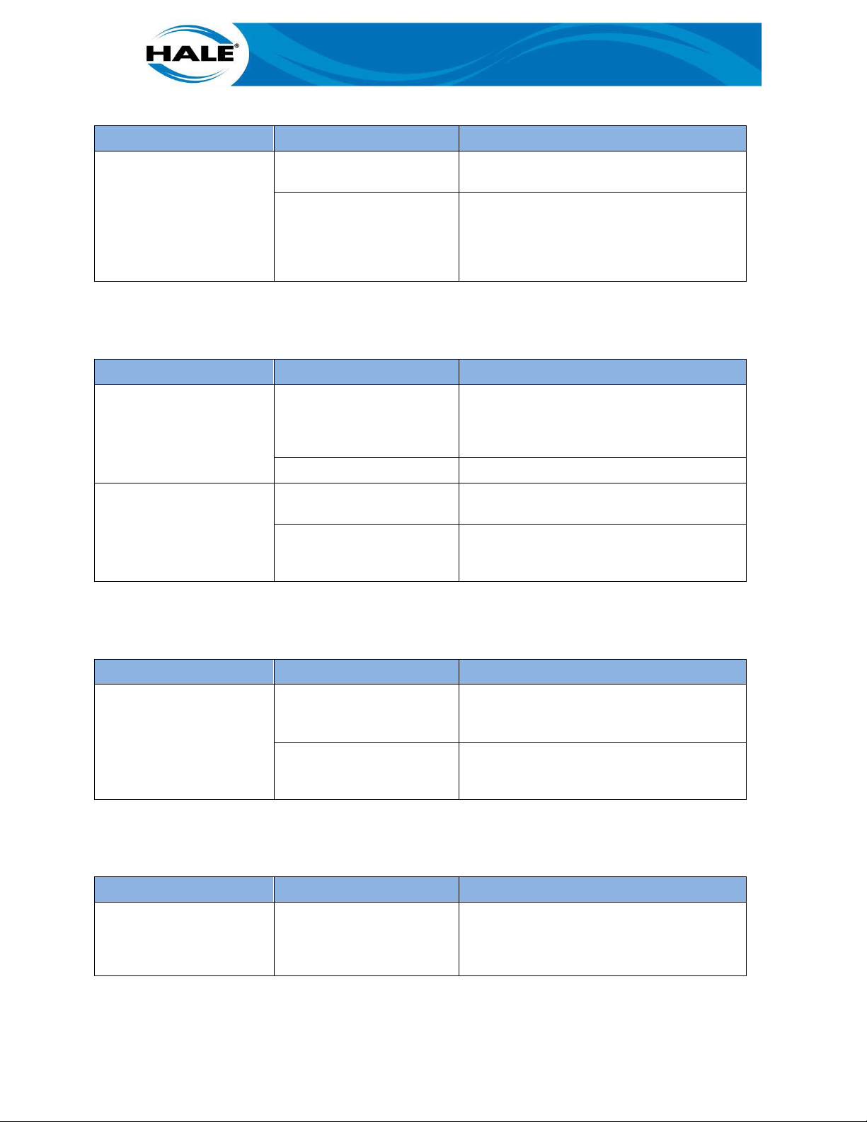
SYMPTOM
CAUSE
REMEDY
SYMPTOM
CAUSE
REMEDY
SYMPTOM
CAUSE
REMEDY
SYMPTOM
CAUSE
REMEDY
Table 14. Engine Speed SCR Table – CONTINUED
Engine Speeds Too High –
CONTINUED
Worn Pump Impeller(s)
And/or Clearance Rings
Impeller Blockage Blockage in the impeller can prevent loss of
5.1.5 Relief Valve Problems
Relief Valve Does Not Relieve Pressure When Valves
Are Closed
Relief Valve Does Not Recover And Return To Original Pressure Setting After
Opening Valves
Incorrect Setting Of Control
Valve (PMD)
Relief Valve Inoperative Refer to the relief valve manual.
Dirt In System Causing
Sticky Or Slow Reaction
Relief Valve Blocked Clean the valve with a small wire or straight-
Installation of new parts required.
both capacity and pressure. Back flushing the
pump from discharge to suction may free
blockage. Removal of the pump head may be
required (this is considered a major repair).
Table 15. Relief Valve SCR Table
Check and repeat proper procedures for setting relief valve system.
(See www.Haleproducts.com and search for
your relief valve for setup instructions.)
Refer to the relief valve manual.
en of a paper clip. Refer to the relief valve
manual.
5.1.6 Gearbox Problems
Table 16. Gearbox SCR Table
Water In Pump Gearbox Leak Coming From Above
Pump
Leaking Mechanical Seal If mechanical seal is installed, there should
5.1.7 Discharge Valve Problems
Table 17. Discharge Valve(s) SCR Table
Discharge Valves Difficult
To Operate
Lack Of Lubrication Recommended weekly lubrication of dis-
Check all piping connections and tank overflow for possible spillage falling directly on to
the pump gearbox.
be no leaks. Inspect the oil seal and replace
if necessary.
charge and suction valve, use an approved
lubricant. Refer to the valve manual for more
information.
46
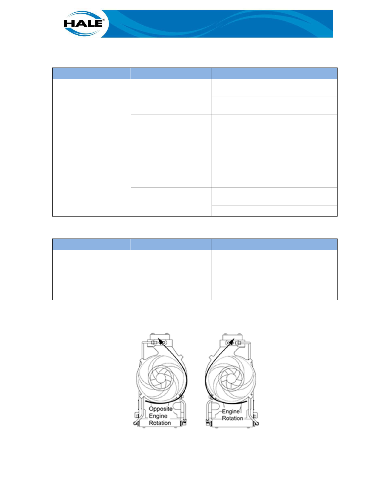
5.1.8 Cavitation
SYMPTOM
CAUSE
REMEDY
SYMPTOM
CAUSE
REMEDY
Table 18. Cavitation SCR Table
Pump Is Cavitating Discharging More Water
Than The Pump Is Taking In
Air Leak Verify air bleeder on the suction tube is not
Drafting Too High Verify lift loss, hose friction, water tempera-
Water Temperature Too
High
Table 19. Rotation SCR Table
Reduced Pressure To
60—100 psi And Reduced
Flow
Wrong Impeller Installed
See Figure 12
Increase the flow into the pump with more
and/or larger intake lines.
Gate the discharge valves to reduce flow and
maintain pressure.
open.
Locate and eliminate all air leaks during
maintenance.
ture and other lift limiting factors are reduced
or eliminated.
Locate the pump closer to the water source.
Reduce volume discharged by lowering RPM
or gating the discharge valves.
Locate a source of cooler water.
Verify the new impeller vanes are oriented
the same as the old impeller before installation. See Figure 12.
Wrong Application The pump was installed on an application for
which it was not intended i.e. front mount vs.
rear mount.
It is possible to reassemble the pump incorrectly or with the wrong parts. Always compare the
replacement parts with the original hardware. (See Figure 12.)
Figure 13. Engine Or Opposite Engine Rotation
47

Contact Hale Customer Service for further assistance by calling the Customer Service Number:
800–533–3569 with the following information.
Pump MODEL NUMBER and SERIAL NUMBER (Refer to Section 2.2, Pump Specifications And
Numbering, in the Hale OIM manual [FSG–MNL–00183] for serial number locations, model
number definitions, and major pump features.)
Observed symptoms and conditions under which the symptoms occur.
5.2. Maintenance Level 1
Maintenance Level 1 consists of basic repair. This includes support of all preventive maintenance and the most common or basic pump/gearbox repairs. This maintenance would include
preventive maintenance inspections, disassembly for cleaning or troubleshooting purposes, and
additionally repair an air/water leak resulting from gasket or seal damage. The Level 1 repair kit
ONLY supports Level 1 maintenance and contains O-rings, oil seals, gaskets, mechanical seal,
and cotter pin for basic reassembly of the pump/gearbox after replacing a failed pump seal or
gearbox oil seal. The kit contents are the recommended spare parts for the first three years (multiple kits may be required during that period) and is intended to be used whenever a Level 1
basic repair is required (repairing a water leak, minor water/oil intrusions, or a failed pump seal).
5.3. Maintenance Level 2
Maintenance Level 2 consists of intermediate maintenance or basic repairs plus wear items
(such as bearings and selected fasteners) and performance testing (typically testing beyond the
first three years). This maintenance level includes support for preventive maintenance performance testing failure and the most common or basic pump/gearbox wear items replacement.
This maintenance would include preventive maintenance performance test failures (flow rate
issues), troubleshooting, and restoration of pump performance resulting from typical wear items
(bearings, seals, gaskets/O-rings, and select fasteners). The Level 2 repair kit supports Level 1
and Level 2 maintenance and provides the contents of the Level 1 kit and the added Level 2
items. A Level 2 kit is recommended as the minimum spare parts for each five year interval of
pump life expectancy.
5.4. Maintenance Level 3
Maintenance level 3 consists of replacement gear set and shaft keys. Before attempting a level 3 repair contact with Hale Customer Service (see Section 5.1, Troubleshooting) is recommended. The Customer would need to be prepared to provide ID plate information (COMPLETE
INFORMATION FROM ALL ID PLATES) for the affected pump and gearbox.
5.5. Maintenance Impeller Renew
The combined use of a level 3 and an impeller renew kit constitutes a complete overhaul of the
pump. This maintenance level is typically considered shop maintenance, in which a complete
tear down and removal and replacement of major parts is required.
The level 3/renew kits are purposed for a complete overhaul of the pump. In addition to the entire contents of the level 2 kit, they supply bearings, retaining rings, select hardware, gaskets
(and/or O-rings), impeller(s), clearance rings, a set of drive gears, and shaft keys. Before attempting a level 3 repair contact with Hale Customer Service (see Section 5.1, TROUBLESHOOTING) is
recommended. The Customer would need to be prepared to provide ID plate information (COMPLETE INFORMATION FROM ALL ID PLATES) for the affected pump and gearbox. Be aware customer service will determine affordability/feasibility of the level 3/renew of a pump before authorizing the parts sale. Remember the combined down time, cost of parts, cost of installation
and testing may make a new pump the more cost effective solution (and includes a new warranty).
48

Dow Corning BR2-PLUS
• Imperial #777
Lubriplate Fiske #3000
• Mobil Grease Special
Shell Super Duty Grease
• Sunoco Moly #2EP
Application
Lubricant 1 /
5.6. Miscellaneous Maintenance
Miscellaneous maintenance consists of procedures to replace pump and/or gearbox components that typically do NOT fail under normal operating conditions. The procedures cover all major components that typically constitute a complete overhaul of the pump.
Before attempting a miscellaneous maintenance repair contact with Hale Customer Service (see
Section 5.1, TROUBLESHOOTING) is recommended for FAST Centers and required for an enduser. (Hale pumps require ONLY trained maintainers perform miscellaneous maintenance.) This
level of maintenance is typically considered shop maintenance, in which a complete tear down
and removal and replacement of select major parts is required. Especially when this level of
maintenance is required the repair must be conducted by a FAST Center or an OEM (supported
but NOT typical). The Customer would need to be prepared to provide ID plate information (COMPLETE INFORMATION FROM ALL ID PLATES) for the affected pump and gearbox.
Unlike level 1 or level 2 maintenance there is no kit to support a complete overhaul of the pump.
With this type of maintenance individual failed components must be ordered. The cost of individual major components and the associated labor for replacing them added to the subsequent required pump testing may be prohibitive. Miscellaneous maintenance procedures are included to
replace all major components (cooler parts, shafts, inducers, impellers, clearance rings, gears,
etc.) however when Hale Customer Service (see Section 5.1, TROUBLESHOOTING) is contacted it
will evaluate the cost associated with the requested components and advise if a replacement
pump (including a new warranty) would be more cost effective.
5.7. General Repair Guidelines
The following subparagraphs provide general guidelines to be utilized and/or followed whenever
the maintenance procedure being performed is associated with the type of information/ instructions provided in these subparagraphs.
5.7.1 Match Mark Or Note Component Orientation
As a general maintenance practice, match mark and/or note (document/record) the orientation
of a component before disconnecting or removing it.
5.7.2 Recommended Lubricants
Where grease is called for, use lithium based grease with 1 to 3% Molybdenum Disulfate. The
following lists examples of approved greases.
•
•
•
The lubricant listed in Table 20 is recommended to protect the O-ring from damage, speeds up
assembly, and to ensure continued service and operation.
Table 20. Recommended O-ring Lubricant
O-ring Synthetic Multi-Purpose Clear O-ring Lubricant
Note 1/: Or equivalent lubricant.
(Synthetic NLGI Grade 2 Heavy Duty, Multi-Purpose)
49
Application
Lubricant 1 /
Fastener Size
Fastener Material
Torque ft-lb (Nm)
Use the lubricant listed in Table 21 to protect the mechanical seals from damage, speeds up assembly, and to ensure continued service and operation.
Table 21. Recommended Mechanical Seal Lubricant
Mechanical Seal P-80 THIX Lubricant Gel (Blend of synthetic esters and water in a thixotropic
formula with a viscosity of about 10,000 cps)
Note 1/: Or equivalent lubricant.
The gearbox lubricants listed in paragraph 7.4.4.1.1, Recommended Gearbox Lubricants, in the
Flex Series Single Stage Booster Pump OIM (FSG–MNL–00183) are required to maintain the
change interval listed in Table 7, Recommended Preventive Maintenance, and to ensure continued service and operation across the required ambient temperature range of– 20 º to +50 ºC
(0 to +120 °F).
5.7.3 Cleaning And Lubrication Required For Mechanical Seal Installation
Before installing the mechanical seal, use the alcohol swabs provided by Hale Products Inc. to
clean all grease or oil from the pump shaft and pump head.
ALWAYS USE AND ONLY USE PAC-EASE RUBBER LUBRICANT EMULSION (OR EQUIVALENT) WHEN INSTALLING THE MECHANICAL SEAL. USING ANY OTHER LUBRICANT OR
NOT USING THE LUBRICANT MAY DAMAGE THE MECHANICAL SEAL AND SEAT.
5.7.4 Replacement Fasteners
Replacement studs must be metric class 8.8 (or better). Apply Loctite™ 680 (or equivalent) to
the housing side threads at the time of install (locker dries to fast to pre-apply).
Replacement screws and steel nuts must be grade 5 (or better) and grade 8 (or better) for drive
line fasteners. Apply Loctite™ 243 (or equivalent) to all threads where lock/spring washers are
NOT used.
Self-locking nuts must be grade 5 (or better), 360O nylon patch lock fasteners. Do NOT reuse
self-locking nuts. Do NOT apply Loctite.
Always remove old thread locker from used fastener threads before installation and torque as
specified in Table 22.
Table 22. Maximum Torque Values
3/8—16 Zinc-Plated Steel 50(68)
3/8—16 Stainless Steel 28(39)
7/16—14 Zinc-Plated Steel 70(95)
50
7/16—14 Stainless Steel 28(39)
M8 x 1.25 Zinc-Plated Steel (Into Aluminum) 12(16)
M10 x 1.5 Unplated Steel Nut 17(23)
M10 x 1.5 Unplated Steel Stud (Into Aluminum) 24(32)
M12 x 1.75 Unplated Steel Stud (Into Aluminum) 40(54)
M12 x 1.75 Unplated Steel Nut (Grade 8) 29(39)

As previously stated, Loctite™ or sealant was used during factory assembly for all fasteners/hardware requiring the use of a thread lock or sealant compound, remnant compound ALWAYS causes false torque reading when installing old and/or new fasteners/hardware. Therefore
ALWAYS clean both sets of threads when installation instructions specify a torque requirement.
Use a cleanout tap (followed by a compressed air/water wash out) for female threads. Use a wire
brush (or die) for male threads (followed by a compressed air/water wash off). Use of a torque
lubricant is NOT required and is allowable ONLY for fasteners/hardware that do NOT require
thread lock or sealant compound. Specific torque requirements are provided within a procedure
when required. General torque values are provided in Table 22.
5.7.5 Circlip/Snap Ring Installation
All circlips (also called snap rings) should be installed with the sharp edge in the direction of
thrust support. If you examine the circlip closely you can determine which side has the sharp
edge by rubbing the edges with your finger. The edge of one side will feel sharp and the other
side will be rounded. The different edges are caused by the punch press stamping the circlips out
of a sheet of steel. Additionally the shape of the circlip is critical and for this reason they should
never be reused once removed. The pumps utilize three types of circlips: internal, external, and
general retaining as shown on Figure 13.
Figure 14. Circlips (How To Recognize And Remove Them)
5.7.6 Thread Lock Or Sealant Compound
Loctite™ (or suitable equivalent/substitute thread locker) or sealant shall be used when directed.
Reference the procedures associated list of tools and/or consumables for the specific thread
locker or sealant required. Loctite™ (243, 680) or sealant (580) was used during factory assembly for all fasteners/hardware requiring the use of a thread lock or sealant compound, remnant
compound ALWAYS causes false torque reading when installing old and/or new fasteners/hardware. See paragraph 5.7.4, Replacement Fasteners, for thread lock or sealant compound cleaning information.
The following Loctite™ compounds were used for thread lock or sealant during factory assembly.
• Thread Lock Compounds
• Sealant
243 580
680
5.7.7 Cleaning And Inspection Guidelines
Wherever a procedure calls for cleaning and inspection, these guidelines should be followed.
A. Inspect all components for excessive or abnormal wear.
B. Wherever a requirement for new parts is indicated, obtain new components
from Hale Products Inc.
51

C. Wherever procedures call for removal of gaskets, gasket should be replaced.
Clean all gasket mating surfaces before installing new gaskets.
D. Bearings and other components should be cleaned using only recommended
solvents.
E. Bearings and seals should be inspected whenever parts are disassembled.
Look for signs of excessive and irregular wear. Replace seals with tears, that
are out-of-round, hardened, cracked, rusted, impact damaged (dents), etc.
F. Replace any hardware (including pump and input shaft keys) that shows
signs of excessive wear.
G. When inspecting impellers and clearance rings for wear, measure impeller
hub diameter and inner diameter of clearance ring. Compare these measurements to data in Table 23. If measurements indicate, obtain replacement
clearance rings and impeller.
NOTE
If either the impeller hub or clearance rings are out-of-tolerance, both rings and the
impeller must be replaced as well as the mechanical seal.
5.7.7.1 Recommended Cleaners
Hale recommends the following:
• Safety Kleen
• Stoddard Solvent
• Loctite Clean-Up Solvent (thread locker removal for hardware and clearance rings)
5.7.8 Repair Kits
Reference the applicable pump drawing REPAIR PART KITS IDENTIFICATION sheet (typically
sheet 3 of 6) for the available level 1, 2, or 3 repair kit part numbers.
5.7.9 Impeller Renew Kits
Reference the applicable pump drawing REPAIR PART KITS IDENTIFICATION sheet (typically
sheet 3 of 6) for the available impeller renew kit part number (or numbers). Refer to the following
paragraph for additional information about the need for installing an impeller renew kit.
5.7.9.1 Worn Clearance Rings And Impeller Hubs
Because clearance ring replacement requires pump disassembly, it is advisable to thoroughly
check other possible causes of low performance before assuming that clearance ring wear is at
fault.
Clearance rings limit the internal bypass of water from the discharge side of the pump back to
the suction side. The radial clearance between the impeller hub and the clearance rings is only a
few thousandths of an inch when new. In clear water, the clearance rings continue to effectively
seal for hundreds of hours of pumping. In dirty or sandy water, the impeller hub and clearance
rings will wear faster. The more wear, the greater the bypass and the lower the pump performance. Refer to Table 23.
52
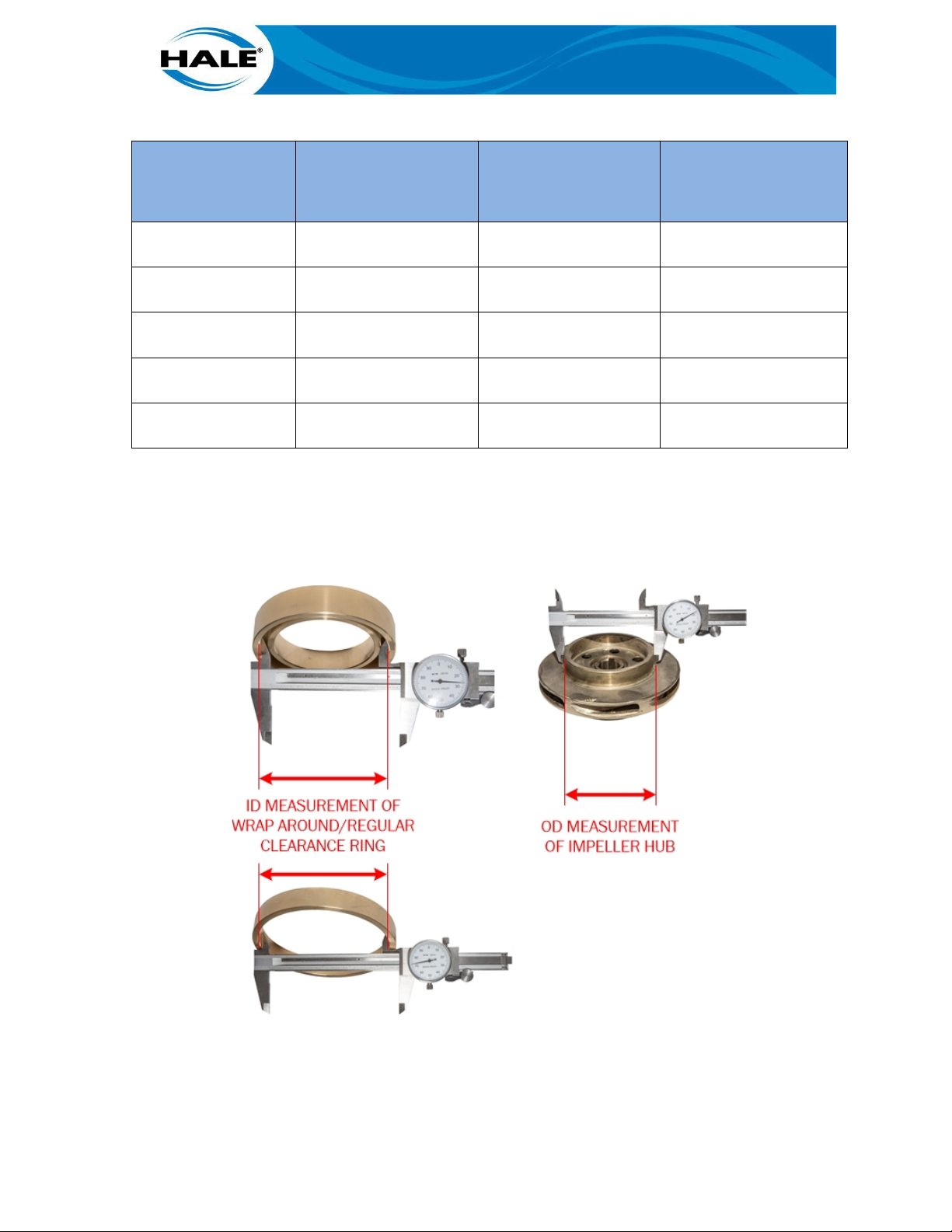
Booster
Pump
Model
Maximum
Clearance Ring
Inner Diameter
in (mm)
Minimum
Impeller Hub
Outer Diameter
in (mm)
Maximum
Acceptable
Radial Clearance
in (mm)
Table 23. Impeller And Clearance Ring Diameters And Clearance Values
AP 4.777
CBP 3.6326
MBP 5.638
RSD
(750-1250 gpm)
RSD
(1500 gpm)
(121.336)
(92.268)
(143.205)
6.022
(152.959)
6.492
(164.897)
4.760
(120.904)
3.620
(91.948)
5.620
(142.748)
5.987
(152.070)
6.419
(163.043)
0.006 — 0.0085
(0.153 — 0.216)
0.0045 — 0.0065
(0.114 — 0.165)
0.0075 — 0.01
(0.1905 — 0.254)
0.0075 — 0.01
(0.1905 — 0.254)
0.0075 — 0.01
(0.1905 — 0.254)
Often, replacement of the clearance rings will reduce the bypass and restore the pump to near
original performance. A complete restoration requires that the impeller also be replaced. Inspect
the front and back of both clearance ring IDs in several places for signs of wear. Measure the
diameter of each ring in several places. Using a caliper as shown on Figure 14, measure the ID of
each clearance ring and the OD of the impeller.
Figure 15. Measuring For Worn Clearance Rings And Impeller Hubs
53

NOTES
Do NOT measure clearance rings prior to installation, installing the ring compresses
the ring which changes the measurement.
Do NOT measure a clearance rings after removing the ring, removing the ring distorts
the ring which changes the measurement.
5.8. Removal And Replacement Instruction Guidelines
Removal and replacement instructions are provided for select components. The instructions provided describe a complete tear down of a booster pump. The tear down instructions are ordered
by the sequence required to remove and replace the target assembly/part. To reduce unnecessary work and to avoid the introduction of additional/new issues, only dismantle the parts as instructed and necessary to accomplish the target inspection and or removal and replacement.
The R&R procedures are written to provide three layers of detail. The “A” steps provide an experienced technician (who is very familiar with a Hale booster pump) a Top Level View of the steps
required to R&R the titled component. The “A” steps along with the “1” steps provide an experienced technician (who is NOT familiar with a Hale booster pump but is familiar with pumps in
general) a more detailed set of steps to R&R the titled component. Using all three levels of the
steps provides an inexperienced technician (training is require for all who work on the pumps)
very detailed steps to perform the task.
5.8.1 Tools Required/Suggested
Individual tool and consumable lists are provided for each procedure. The following tools are the
minimum required to perform maintenance/repairs on the pumps contained in this manual.
• Allen Wrenches (or Hex Socket Set)
• Ball Peen Hammer
• Bearing/Seal Driver Kit (See Figure 15.)
• By hand Push Tube
(a small section of PVC tubing to fit over/around shafts used as a special tool)
• Caliper (12 in) (See Figure 16.)
• Catch Pan (To Catch Oil)
• Center Punch
• Cutting Wheel/Grinder (Electric or Pneumatic)
• Dental Pick Set
• Drift Punch
• Funnel
• Hacksaw
• Hose Removal Tool
• Hydraulic Press
• Impact Driver
• Infrared Thermometer (Precise Non-Contact IR)
(See APPENDIX B, Test Equipment And Special Tool Information)
• Lift and Rigging Devices (Lever Hoist or Chain Hoist) and (Short Strap Or Choker)
• Non-marring Hammer
• Non-marring Pliers
• Oil Dry
• Pin Punch
• Pry Bar (2)
• Puller (Bearing/Impeller) (See APPENDIX B, Test Equipment And Special Tool Information)
54

• Pump Shaft Hydraulic Press Adapter
(a piece of 3-inch diameter, schedule 40, steel pipe, 10-inches long used as a special tool)
• Ratchet(s), Sockets, and Wrenches
• Screwdriver Set
• Seal Removal Tool (See Figure 15.)
• Shop Rags
• Snap Ring Pliers
• Torque Wrench(s) Or Torque Limiting Socket(s)
(Capable of 10, 17, 18, 19, 29, 30, 33, 40, 45, 50, 53, 59, 65, and 135 ft-lb [14, 23, 24,
26, 39, 41, 45, 54, 60, 68,72,79, 88, and 183 Nm])
(See APPENDIX B, Test Equipment And Special Tool Information)
• Wheel Chocks
• Wire Cutter
• Wire Tags
• Wooden Wedges
Figure 16. Seal Removal Tool And Seal Driver Kit
Figure 17. Caliper (Depth Rod Extended)
5.8.2 General Pump Disassembly For Access Guidelines
Before working on the pump, disconnect the suction and discharge piping and drain the volute.
Disconnect cooling tubes from the pump as required.
Label/tag and then disconnect all wiring leaving the sensor/switch/valve on the pump.
The Hale booster pump design allows two methods of pump maintenance. If only pump components require removal and replacement the maintainer may be able to repair the pump without
pump removal from apparatus depending on the apparatus configuration (pump access). See
the appropriately titled subparagraph under section 5.8.3, AP Pump Disassembly, to R&R pump
components without removing the pump from the apparatus.
55

Standard Tools
Special Tools
Consumables
If the gearbox requires internal component replacement or the apparatus configuration does
NOT allow pump access the maintenance method requires both pump and gearbox be removed
as an assembly from the apparatus. (See paragraph 5.8.2.1, AP Removal From The Apparatus.)
When AP gearbox and/or pump maintenance or repairs (which required method two, which supports gearbox component repairs or pump repairs when pump access is NOT possible) are completed, the AP pump/gearbox installation back onto the apparatus is accomplished by following
the instructions in paragraph 5.8.8, AP Install On The Apparatus.
Read and understand all the instructions before beginning any pump removal or replacement.
5.8.2.1 General Pump Removal From The Apparatus
Refer to Table 24 for a list of tools and/or consumables required for this procedure.
Table 24. Pump R&R From The Apparatus Tools And Consumables List
PPE (Eye and Hand Protection) None ** Shop Rag(s) (As Required)
PPE (For Handling Oil) Tags (Wire, Etc.)
Catch Pan (For Gear Oil)
Wheel Chocks
Lifting Device And Rigging
(Or Jack)
9/16-in Socket (8 Pt.) And Ratchet
(Or Wrench Or Adjustable Wrench)
** None for pump – see OEM/Apparatus documentation for a complete list.
THE AP PUMP AND GEARBOX ASSEMBLIES WEIGH APPROXIMATELY 140 LBS
(64 KG). USE PROPER LIFTING DEVICE WHEN REMOVING OR INSTALLING THE PUMP
AND GEARBOX ASSEMBLY.
THE CBP PUMP AND GEARBOX ASSEMBLIES WEIGH APPROXIMATELY 100 LBS
(45 KG). USE PROPER LIFTING DEVICE WHEN REMOVING OR INSTALLING THE PUMP
AND GEARBOX ASSEMBLY.
THE MBP PUMP AND GEARBOX ASSEMBLIES WEIGH APPROXIMATELY 170 LBS
(77 KG). USE PROPER LIFTING DEVICE WHEN REMOVING OR INSTALLING THE PUMP
AND GEARBOX ASSEMBLY.
THE RSD PUMP AND GEARBOX ASSEMBLIES WEIGH APPROXIMATELY 225 LBS
(102 KG). USE PROPER LIFTING DEVICE WHEN REMOVING OR INSTALLING THE
PUMP AND GEARBOX ASSEMBLY.
56
A. Prepare apparatus/vehicle for pump removal.
Place apparatus out of service in accordance with departmental proce-1.
dures.
Park vehicle on level surface. 2.

Set parking brake and chock front and rear wheels. 3.
B. Disassemble/remove all items required to access pump and gearbox. See
Figure 17.
Support pump and gearbox using appropriately sized lifting device and 1.
rigging or jack.
Match mark and tag all items/connections before removal. 2.
Remove ONLY items/connections required to access pump and gearbox. 3.
Follow all OEM provided instructions to disassemble/remove items when 4.
required to access pump and gearbox.
C. Prepare pump for removal.
Remove drain plugs (water ONLY – do NOT drain oil until instructed) and 1.
drain pump.
Place catch pan under magnetic oil drain plug. 2.
Figure 18. Pump And Gearbox Assembly R&R
Remove magnetic oil drain plug. (See Figure 17.) 3.
57

a) Using 9/16-in socket (8 point) and ratchet (set for CCW), loosen drain plug.
b) Remove drain plug.
Wait for oil flow to stop. 4.
NOTE
Check for metal accumulation on drain plug. Metal accumulation provides clues and
insight as to gearbox component health.
Clean drain plug. 5.
Install drain plug. 6.
a) Hand start drain plug.
b) Using 9/16-in socket (8 point) and ratchet (set for CW), tighten drain plug.
c) Using shop rag(s), clean drain plug area.
Examine oil for water. 7.
NOTE
Water turns the oil a milky color or settles in the bottom of the catch pan.
Dispose of oil properly. 8.
Disconnect drive shaft from drive flange. 9.
Tag and disconnect airlines, electronics, and tachometer cable as re-10.
quired.
THE AP PUMP AND GEARBOX ASSEMBLIES WEIGH APPROXIMATELY 140 LBS
(64 KG). USE PROPER LIFTING DEVICE WHEN REMOVING OR INSTALLING THE PUMP
AND GEARBOX ASSEMBLY.
Disconnect mounting brackets at pump and gearbox assembly. 11.
D. Remove pump and gearbox from apparatus. See Figure 17.
Using lifting device (or jack), lift (or lower) pump and gearbox free from 1.
apparatus.
Place pump and gearbox assembly on stable work stand so that breather 2.
and gearbox cover are exposed.
NOTE
This positioning will provide easy and safe access to the internal components.
5.8.3 General Pump Disassembly Methodology
Please review the general repair (section 5.7) and cleaning and inspection guidelines (section 5.7.7) before beginning these procedures.
The Hale Flex Series single stage booster pumps design separates the four pumps into two
groups based on the volute. The first group (the AP, CBP, and MBP) utilizes a one-piece volute
(see Figure 18) while the second (the RSD) utilizes a three-piece volute (see Figure 19). This
makes the RSD pump disassembly unique among the Hale booster pumps. The RSD three-piece
volute consists of the suction head, the body (volute), and the pump head. Additionally, the pump
is unique in that the volute provides a side discharge flange to support ancillary equipment (typically a TRV).
58

Figure 19. One-Piece Volute (AP, CBP, MBP)
Figure 20. Three-Piece Volute (RSD)
59

No matter which group requires maintenance, the Hale Flex Series single stage booster pump
design allows two methods of pump maintenance. In the first method (and the preferred method
when only pump components require removal and replacement) the maintainer may be able to
repair the pump without removing the pump and gearbox from the apparatus. Even though the
Hale pump design allows the pump component to be removed without removing the pump and
gearbox, the apparatus installation may prevent pump component removal without first removing
the pump and gearbox. This is due to limited pump access when the pump is installed on the
apparatus (as the pump is typically located between the frame rails and under other apparatus
components). Therefore use of this method depends on the apparatus configuration (pump access). If the apparatus configuration allows pump component ONLY removal, see the appropriately titled subparagraph for the pump component that requires R&R.
If the gearbox requires internal component replacement or the apparatus configuration does
NOT allow pump access the maintenance method requires the pump and gearbox be removed
from apparatus as one assembly. If the apparatus configuration does NOT allow pump component ONLY removal or if the gearbox requires repair, see paragraph 5.8.2.1, General Pump Removal From The Apparatus for generalized removal instructions.
No matter which method of removal is utilized; Figure 20 provides an exploded view of the AP
pump, Figure 21 provides an exploded view of the CBP pump, and Figure 22 provides an exploded view of the MBP pump, and Figure 23 provides an exploded view of the RSD pump to support
Level 1 maintenance procedures. Figure 24 and Figure 25 provide exploded views of the gearbox
(based on gear ratio) for support of Level 2 and/or 3 maintenance procedures. Impeller renew
and miscellaneous maintenance procedures require the combination of both the applicable
pump and applicable gearbox figures to provide adequate support. Note: Figure 25 additionally
shows the optional gearbox cooling components, which (in addition to the gearbox cover) must
be removed to replace the drive gear. The gearbox cover and the optional cooling tube must also
be removed to replace some, pump gears. Removal is required for pumps with 1.14, 1.31, 1.64,
and 1.90:1 gear ratios as the pump gear is too large to exit via the gearbox bearing bores.
Under any circumstances, do NOT remove a pump as an assembly (the entire unassembled
pump) from the gearbox. Doing so leaves the pump shaft unsupported and allows significant
damage to the internal pump components. Removing the pump as an entire assembly may result
in catastrophic damage to the clearance rings, impeller, and the mechanical seal.
Regardless of the maintenance level, read and understand all the instructions before beginning
any pump and especially a gearbox repair.
60

61
Figure 21. AP Pump Exploded View
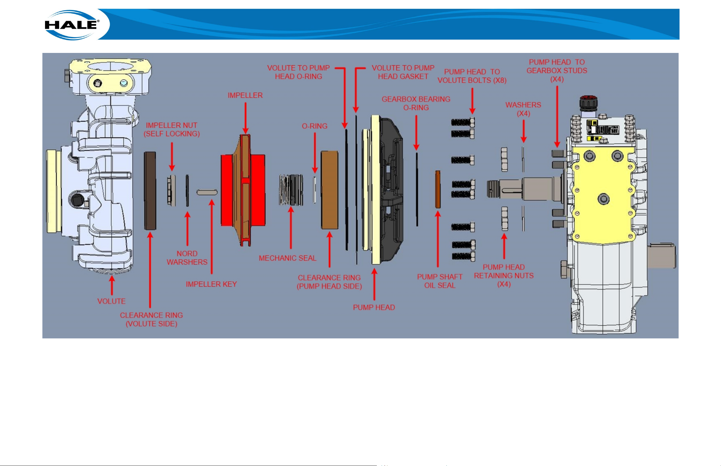
62
Figure 22. CBP Pump Exploded View
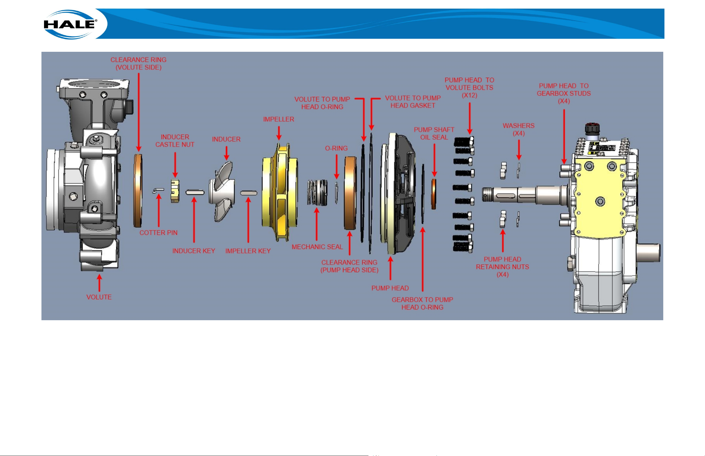
63
Figure 23. MBP Pump Exploded View

64
Figure 24. RSD Pump Exploded View
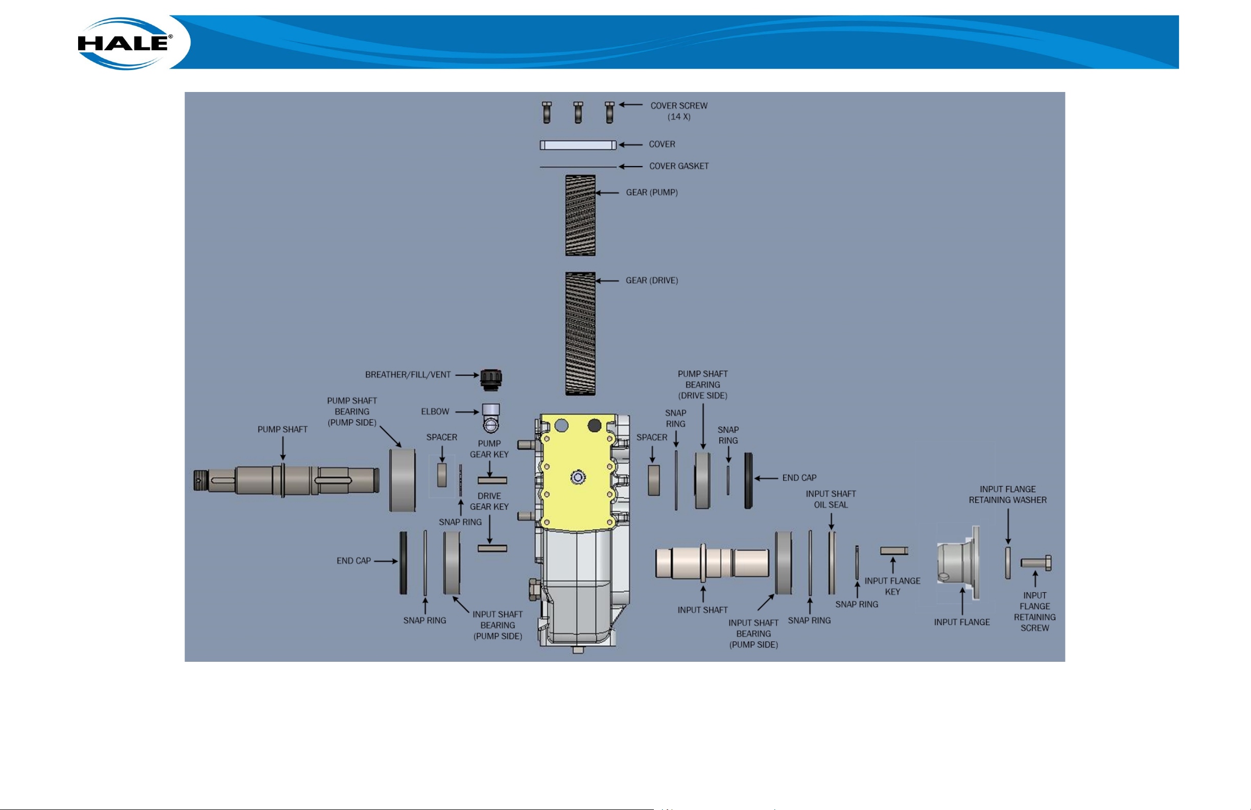
65
Figure 25. Gearbox Exploded View (All Except 3.74:1 GR)
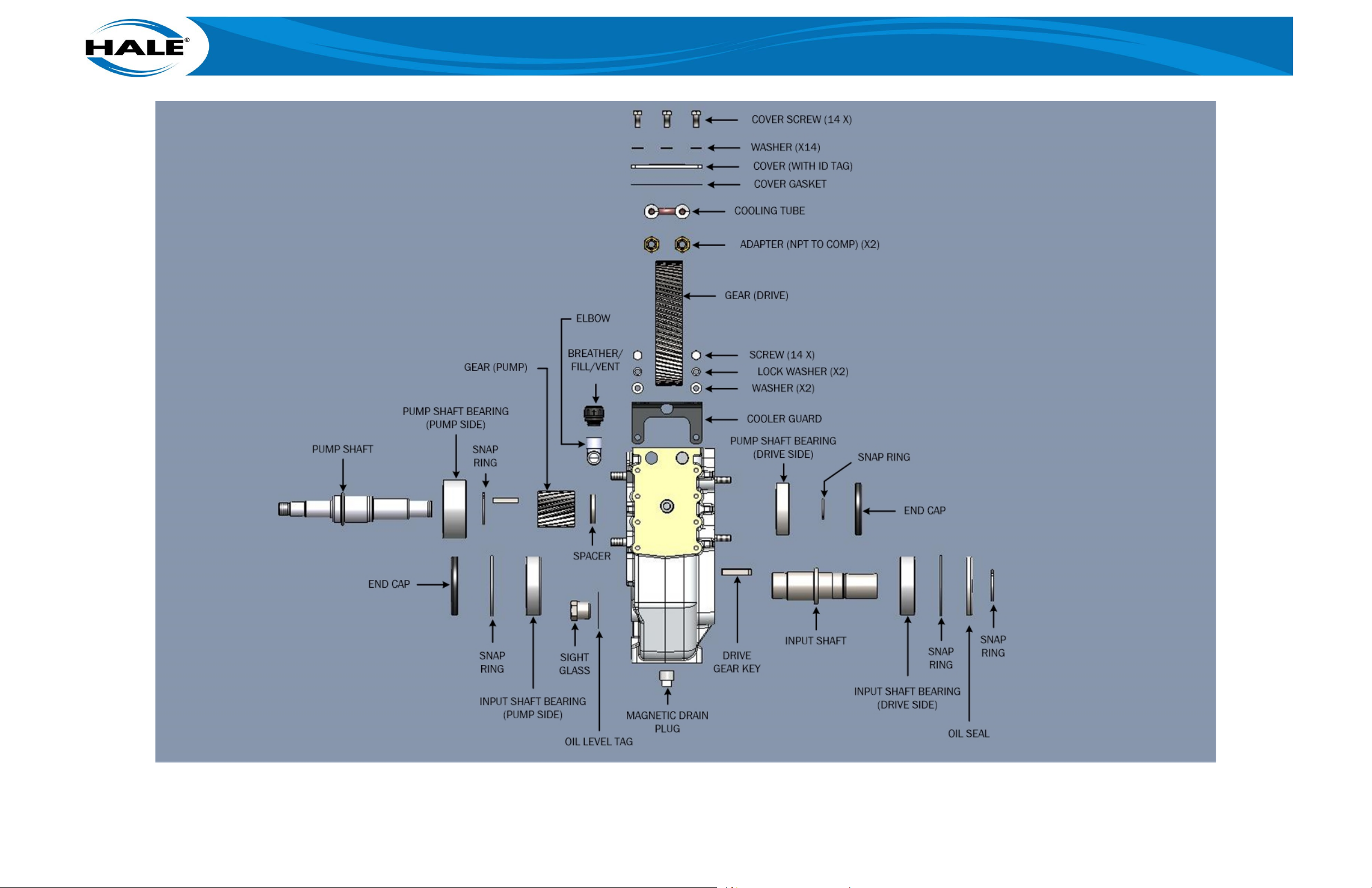
66
Figure 26. Gearbox Exploded View (3.74:1 GR)
Standard Tools
Special Tools
Consumables
5.8.4 Level 1 Procedures
If pump access permits, selected pump components (see Figure 20, Figure 21, or Figure 22) can
be removed and replaced without removing the pump and gearbox assembly from the apparatus.
Discharge and suction port hoses/plumbing may require removal before the selected pump
component R&R procedure can be performed. Follow OEM instructions/procedures to remove
and install discharge and/or suction port hoses/plumbing when required for pump component
access. The following pump components can be removed and replaced without removing the
pump and gearbox assembly from the apparatus.
• Gaskets and O-rings • Pump Shaft Oil Seal
• Mechanical Seal • Input Shaft Oil Seal
Air and/or water leaks may occur at the volute joints as a result of gasket or O-ring damage or
wear. This may be indicated by symptoms of cavitation or poor performance (see section 5.1,
Troubleshooting) or be visually noticeable as water stains or mineral deposits appearing from the
volute to pump head joint.
5.8.4.1 RSD Suction Head R&R
In addition to gasket/O-ring failure the suction head requires removal to examine or access internal pump components (suction side clearance ring, inducer, or impeller). Typically the suction
head would not require replacement unless it has been damaged by allowing the pump to freeze
with water in it or a large piece of debris was allowed into the pump by not using or maintaining
strainers.
NOTE
If the joint between the suction head and the volute appears to be leaking water or
the suction head is damaged, suction head removal is required. If a leak is indicated,
water staining will appear on the paint between the assemblies. Additionally mineral
deposits may also indicate a leak at the joint.
Refer to Table 26 for a list of tools and/or consumables required for this procedure.
Table 25. RDS Suction Head R&R Tools And Consumables List
PPE
(Eye and Hand Protection)
5/8-in Wrench
(Or Ratchet And Socket)
(Or Pass Thru Ratchet)
Hooked-end Dental Pick (or
Hose Removal Tool)
None Shop Rag(s) (As Required)
O-ring Lubricant (See Table 20)
O-RING <See FSG–PL-01487, Sheet 4, Item 30>
(Suction Head To Volute)
Gasket Scrapper Gasket <See FSG–PL-01487, Sheet 4, Item 3>
(Suction Head To Volute)
Non-marring Hammer Suction Head: (ONLY ONE REQUIRED – SELECT FROM:)
<See FSG–PL-01487, Sheet 4, Table B>
Loctite™ Clean-Up Solvent
Loctite™ 243 (Or Equivalent)
67

Perform the following to remove and replace the suction head.
NOTES
Remove any suction tube and/or piping blocking access to the pump per
OEM/equipment manufacturer instructions.
Remove any discharge piping blocking access to the pump per OEM/equipment
manufacturer instructions.
RSD Suction Head Removal
A. If pump is still in apparatus, match mark/note/tag and then disconnect suc-
tion, discharge, and cooling lines.
B. If pump is still in apparatus, tag and disconnect any electrical wiring.
C. Match mark suction head to volute to ensure proper alignment during reas-
sembly (volute position may vary).
D. If pump is still in apparatus, disconnect ONLY mounting bracket(s) required
for suction head removal.
E. Remove eight (8) 7/16 — 14 X 1.25–in screws that hold suction head to vol-
ute.
NOTE
Do NOT damage clearance ring or inducer during suction head removal.
F. Remove four (4) 7/16 — 14 X 2.63–in studs that hold suction head to volute.
G. Remove suction head from volute.
NOTE
Gentile tapping with a non-marring hammer may be required to loosen the suction
head from the volute.
H. Remove O-ring from suction head.
I. Remove all remaining gasket material from mating surfaces of volute and
suction head.
Measure suction side clearance ring (see Table 23.), replace if out-of-tolerance. If the clearance
rings have failed, perform RSD Clearance Ring R&R (see paragraph 5.8.7.2 on page 110). If the
impeller has failed, perform Impeller R&R (see paragraph 5.8.4.6 on page 81). If the mechanical
seal has failed, perform RSD Mechanical Seal R&R (see paragraph 5.8.4.10 on page 93).
RSD Suction Head Installation
A. Apply a small amount of grease to a new gasket and align gasket on suction
head.
B. Apply O-ring lubricant to a new suction head O-ring.
C. Using care NOT to damage O-ring, install O-ring on suction head.
D. Align bolt holes and match mark(s) then push suction head into volute.
68

NOTES
Unless match marking differs, place the two (2) casting bosses at the 6 o-clock position on the volute (see Figure 19) regardless of volute orientation.
Gentile tapping with a non-marring hammer may be required to seat the suction head
on the volute.
Use care NOT to damage (pinch) the O-ring if using the bolts to pull the suction head
onto the volute (especially if the suction head is angled). Additional O-ring lubricant
may be required.
E. Install fasteners.
Clean original fastener threads (or replace with the correct new fasten-1.
ers).
Apply Loctite™ 243 (or equivalent) to threads of fasteners. 2.
Install four (4) 7/16 — 14 X 2.63–in studs that hold suction head to vol-3.
ute.
Install eight (8) 7/16 — 14 X 1.25–in screws that hold suction head to 4.
volute.
Refer to Table 22 for recommended torque values for fastener size and 5.
material.
F. Connect mounting bracket(s) as noted/match marked.
G. Connect any electrical wiring according to tags.
H. Connect all suction, discharge, and cooling tubing and piping as noted/match
marked.
I. Perform paragraph 4.4.4.1.3, Performance Testing Test Procedure, to verify
repair complete and pump in working condition. Repair any leaks or problems. (See page 41.)
J. Update maintenance log entries.
K. Place apparatus in service in accordance with departmental procedures.
5.8.4.2 RSD Volute R&R
In addition to gasket/O-ring failure the pump body components require removal to examine or
access internal pump components (clearance rings, inducer, impeller, or mechanical seal). Typically, the volute would not require replacement unless it has been damaged by allowing the
pump to freeze with water in it or a large piece of debris was allowed into the pump by not using
or maintaining strainers.
The RSD volute removal does NOT require suction head removal unless required for access purposes.
NOTE
If the joint between the volute and the pump head appears to be leaking water or the
volute is damaged, volute removal is required. If a leak is indicated, water staining
will appear on the paint between the assemblies. Additionally mineral deposits may
also indicate a leak at the joint.
Refer to Table 26 for a list of tools and/or consumables required for this procedure.
69
Standard Tools
Special Tools
Consumables
Table 26. RSD Volute R&R Tools And Consumables List
PPE
(Eye and Hand Protection)
5/8-in Wrench
(Or Ratchet Wrench)
(Or Pass Thru Ratchet)
Hooked-end Dental Pick (or
Hose Removal Tool)
Adjustable Wrench (For
cooling tubing removal)
Gasket Scrapper Gasket <See FSG–PL-01487, Sheet 4, Item 3> (Two
Non-marring Hammer Volute: (ONLY ONE REQUIRED – SELECT FROM: )
Loctite™ Clean-Up Solvent
Loctite™ 243 (Or Equivalent)
None Shop Rag(s) (As Required)
O-ring Lubricant (See Table 20.)
O-RING <See FSG–PL-01487, Sheet 4, Item 30> (Two
Required)
(Suction Head To Volute) (Volute To Pump Head)
Grease (See paragraph 5.7.2, Recommended Lubri-
cants.)
Required)
(Suction Head To Volute) (Volute To Pump Head)
<See FSG–PL-01487, Sheet 4, Item 29>
Perform the following to remove and replace the volute.
NOTES
Remove any suction tube and/or piping blocking access to the pump per
OEM/equipment manufacturer instructions.
Remove any discharge piping blocking access to the pump per OEM/equipment
manufacturer instructions.
RSD Volute Removal
A. If pump is still in apparatus, match mark/note/tag and then disconnect suc-
tion, discharge, and cooling lines.
B. If pump is still in apparatus, tag and disconnect any electrical wiring.
C. Match mark volute and pump head to ensure proper alignment during reas-
sembly.
D. If pump is still in apparatus, disconnect ONLY mounting bracket(s) required
for volute removal.
E. Using 5/8-in ratchet wrench (or pass thru ratchet set CCW), remove
twelve (12) 7/16 — 14 X 1.25–in screws that hold volute to pump head.
NOTE
Do NOT damage brass clearance rings, inducer, or impeller during volute removal.
70

F. Remove volute from pump head.
NOTE
Gentile tapping with a non-marring hammer may be required to loosen the volute
from the pump head.
G. Remove all remaining gasket material from mating surfaces of volute and
pump head.
Measure clearance rings and impeller hub (see Table 23.), replace if out-of-tolerance. If the
clearance rings have failed, perform RSD Clearance Ring R&R (see paragraph 5.8.7.2 on
page 110). If the impeller has failed, perform Impeller R&R (see paragraph 5.8.4.6 on page 81).
If the mechanical seal has failed, perform RSD Mechanical Seal R&R (see paragraph 5.8.4.10 on
page 93).
RSD Volute Installation
A. Apply a small amount of grease to a new gasket and align gasket on pump
head.
B. Apply O-ring lubricant to a new pump head O-ring.
C. Using care NOT to damage O-ring, install O-ring on pump head.
D. Using care NOT to damage clearance rings or impeller, install volute onto
pump head.
NOTE
Gentile tapping with a non-marring hammer may be required to seat the volute onto
the pump head. Using the bolts to pull the volute (especially if the volute is angled)
into the pump head may damage the O-ring.
E. Install volute fasteners.
Clean original fastener threads (or replace with the correct new fasten-1.
ers).
Apply Loctite™ 243 (or equivalent) to threads of fasteners. 2.
Install twelve (12) 7/16 — 14 UNC x 1.25-in screws that hold volute to 3.
pump head.
Refer to Table 22 for recommended torque values for fastener size and 4.
material.
F. Connect mounting bracket(s) as noted/match marked.
G. Connect any electrical wiring according to tags.
H. Connect all suction, discharge, and cooling tubing and piping as noted/match
marked.
I. Perform paragraph 4.4.4.1.3, Performance Testing Test Procedure, to verify
repair complete and pump in working condition. Repair any leaks or problems. (See page 41.)
J. Update maintenance log entries.
K. Place apparatus in service in accordance with departmental procedures.
71

Standard Tools
Special Tools
Consumables
5.8.4.3 AP/MBP Volute R&R
In addition to gasket/O-ring failure the volute requires removal to examine or access internal
pump components (clearance rings, impeller, mechanical seal, etc.). See Figure 26 for AP volute
removal. Typically the volute would not require replacement unless it has been damaged by allowing the pump to freeze with water in it or a large piece of debris was allowed into the pump by
not using or maintaining strainers.
Figure 27. AP/MBP Volute R&R
Refer to Table 27 for a list of tools and/or consumables required for this procedure.
Table 27. AP Volute R&R Tools And Consumables List
PPE
(Eye and Hand Protection)
Gasket Scrapper O-ring Lubricant (See Table 20 )
Hooked-end Dental Pick
(or Hose Removal Tool)
5/8-in Wrench
(Or Ratchet Wrench)
(Or Pass Thru Ratchet)
5/8-in Torque Wrench Volute: (ONLY ONE REQUIRED – SELECT FROM: )
Loctite™ Clean-Up Solvent
Loctite™ 243 (Or Equivalent)
None Shop Rag(s) (As Required)
O-RING, <See FSG–PL–01483 Sheet 4 Item 7>
(Volute to Pump Head)
Gasket <See FSG–PL–01483 Sheet 4 Item 6>
(Volute to Pump Head)
<See FSG–PL–01483 Sheet 4 Item 1>
72

Perform the following to remove and replace the volute.
NOTES
Remove any suction tube and/or piping blocking access to the pump per
OEM/equipment manufacturer instructions.
Remove any discharge piping blocking access to the pump per OEM/equipment
manufacturer instructions.
AP/MBP Volute Removal
A. If pump is still in apparatus, match mark/note/tag and then disconnect suc-
tion, discharge, and cooling lines.
B. If pump is still in apparatus, tag and disconnect any electrical wiring.
C. Match mark volute and pump head to ensure proper alignment during reas-
sembly.
D. If pump is still in apparatus, disconnect ONLY mounting bracket(s) required
for volute removal.
E. Remove twelve (12) 7/16 — 14 X 1.25–in bolts that hold volute to pump
head.
Using 5/8-in wrench (or ratchet wrench or pass thru ratchet [set CCW]), 1.
loosen twelve (12) 7/16 — 14 X 1.25–in bolts.
Remove twelve (12) 7/16 — 14 X 1.25–in bolts. 2.
NOTE
Do NOT damage brass clearance rings or impeller during volute removal.
F. Remove volute from pump head.
G. Remove O-ring from pump head.
H. Remove all remaining gasket material from mating surfaces of volute and
pump head.
Measure clearance rings and impeller hub, replace if out-of-tolerance (see Table 23). If the
clearance rings have failed, perform Clearance Ring R&R (see paragraph 5.8.7.2 on page 110).
If the impeller has failed, perform Impeller R&R (see paragraph 5.8.4.7 on page 83). If the mechanical seal has failed, perform Mechanical Seal R&R (see paragraph 5.8.4.9 on page 90).
AP/MBP Volute Installation
A. Prepare volute for installation.
Install new O-ring. 1.
a) Lubricate O-ring. Refer to Table 20.
b) Install new O-ring on pump head into O-ring groove on pump side.
Install new gasket. (Align new gasket with pump head screw holes.) 2.
B. Using care NOT to damage clearance rings or impeller, install volute onto
pump head.
C. Install volute fasteners.
73

Standard Tools
Special Tools
Consumables
Clean original fastener threads (or replace with the correct new fasteners) 1.
and volute screw hole threads. (Loctite Clean-up Solvent)
Apply Loctite™ 243 (or equivalent) to threads of fasteners. 2.
Hand start twelve (12) 7/16 — 14 UNC x 1.25-in bolts that hold volute to 3.
pump head.
Using a 5/8-in wrench (or ratchet wrench or pass thru ratchet) tighten 4.
(CW) twelve (12) 7/16 — 14 UNC x 1.25-in bolts.
Using circular pattern, torque twelve (12) 7/16 — 14 UNC x 1.25-in bolts. 5.
Refer to Table 22 for recommended torque values for fastener size and
material.
D. Connect mounting bracket(s) as noted/match marked.
E. Connect any electrical wiring according to tags.
F. Connect all suction, discharge, and cooling tubing and piping as noted/match
marked.
G. Perform paragraph 4.4.4.1.3, Performance Testing Test Procedure, to verify
repair complete and pump in working condition. Repair any leaks or problems.
H. Update maintenance log entries.
I. Place apparatus in service in accordance with departmental procedures.
5.8.4.4 CBP Volute R&R
The primary difference between the CBP and the AP/MBP volute removal is the number of
screws that hold the volute to the pump head, the CBP uses only eight (8) 3/8-in–16 by 0.88 in
long screws instead of the twelve (12) larger screws.
NOTE
If the joint between the volute and the pump head appears to be leaking water or the
volute is damaged, volute removal is required. If a leak is indicated, water staining
will appear on the paint between the assemblies. Additionally mineral deposits may
also indicate a leak at the joint.
Refer to Table 28 for a list of tools and/or consumables required for this procedure.
Table 28. CBP Volute R&R Tools And Consumables List
PPE
(Eye and Hand Protection)
Gasket Scraper Loctite™ 243 (Or Equivalent)
9/16-in Wrench
(Or Ratchet Wrench)
(Or Pass Thru Ratchet)
None Shop Rag(s) (As Required)
Volute: (ONLY ONE REQUIRED – SELECT FROM: )
< See FSG–PL–01482 Sheet 4 Item 1>
9/16-in Torque Wrench O-ring Lubricant (See Table 20 )
74

Standard Tools
Special Tools
Consumables
Table 28. CBP Volute R&R Tools And Consumables List – CONTINUED
Hooked-end Dental Pick
(or Hose Removal Tool)
Gasket <See FSG–PL–01482 Sheet 4 Item 10>
Loctite Clean-Up Solvent
O-RING, <See FSG–PL–01482 Sheet 4 Item 9>
(Volute to Pump Head)
(Volute to Pump Head)
Perform the following to remove and replace the volute.
NOTES
Remove any suction tube and/or piping blocking access to the pump per
OEM/equipment manufacturer instructions.
Remove any discharge piping blocking access to the pump per OEM/equipment
manufacturer instructions.
CBP Volute Removal
A. If pump is still in apparatus, match mark/note/tag and then disconnect suc-
tion, discharge, and cooling lines.
B. If pump is still in apparatus, tag and disconnect any electrical wiring.
C. Match mark volute and pump head to ensure proper alignment during reas-
sembly.
D. If pump is still in apparatus, disconnect ONLY mounting bracket(s) required
for volute removal.
E. Remove eight (8) 3/8 — 16 X 7/8–in bolts that hold volute to pump head.
Using 9/16-in wrench (or socket and ratchet [set CCW]), loosen eight (8) 1.
3/8 — 16 X 7/8–in bolts.
Remove eight (8) 3/8 — 16 X 7/8–in bolts. 2.
NOTE
Do NOT damage brass clearance rings or impeller during volute removal.
F. Remove volute from pump head.
G. Remove all remaining gasket material from mating surfaces of volute and
pump head.
Measure clearance rings and impeller hub, replace if out-of-tolerance (see Table 23). If the
clearance rings have failed, perform Clearance Ring R&R (see paragraph 5.8.7.2 on page 110).
If the impeller has failed, perform Impeller R&R (see paragraph 5.8.4.7 on page 83). If the mechanical seal has failed, perform Mechanical Seal R&R (see paragraph 5.8.4.9 on page 90).
CBP Volute Installation
A. Prepare volute for installation.
Install a new gasket. 1.
Align gasket with screw holes in pump head. 2.
75

B. Using care NOT to damage clearance rings or impeller, install volute onto
pump head.
C. Install volute fasteners.
Clean original fastener threads (or replace with the correct new fasteners) 1.
and volute screw hole threads. (Loctite Clean-Up Solvent)
Apply Loctite™ 243 (or equivalent) to threads of fasteners. 2.
Hand start eight (8) 3/8 — 16 X 7/8–in bolts (with washers) that hold vol-3.
ute to pump head.
Using a 9/16-in wrench (or ratchet wrench or pass thru ratchet) tighten 4.
(CW) eight (8) 3/8 — 16 X 7/8–in bolts.
Using circular pattern, torque eight (8) 3/8 — 16 X 7/8–in bolts. 5.
Refer to Table 22 for recommended torque values for fastener size and
material.
D. Connect mounting bracket(s) as noted/match marked.
E. Connect any electrical wiring according to tags.
F. Connect all suction and discharge tubing/piping as noted/match marked.
G. Perform paragraph 4.4.4.1.3, Performance Testing Test Procedure, to verify
repair complete and pump in working condition. Repair any leaks or problems. (See page 41.)
H. Update maintenance log entries.
I. Place apparatus in service in accordance with departmental procedures.
5.8.4.5 MBP/RSD Inducer R&R
Typically, the inducer would not require replacement unless it has been damaged by allowing a
large piece of debris into the pump by not using or maintaining strainers. Long term wear can
damage an inducer to the point it must be replaced to maintain pump performance specifications.
When the MBP inducer R&R is performed without removing the volute, installing the cotter pin
may be difficult with the volute in place. The preferred method would be prior to performing this
procedure, remove the MBP volute as described in paragraph 5.8.4.3, Volute R&R (page 72).
For either pump, if the volute is removed when the inducer requires replacement, always inspect
(measure) the clearance rings and the impeller before installing the new inducer. Refer to
Table 23 for the impeller wear specifications. If the clearance rings are out-of-tolerance they require replacement, see Pump Clearance Ring R&R (paragraph 5.8.7.2 on page 110) for an MBP
or RSD. If the impeller is out-of-tolerance it requires replacement, see paragraph 5.8.4.6
(page 81), Impeller R&R for either pump. Figure 27 shows the MBP pump with the volute removed and depicts the inducer removal.
76
NOTE
For the RSD pump, if pump performance is an issue and the clearance rings/impeller
are suspect, remove the volute instead of the suction head to provide access to the
impeller and rear clearance ring. See paragraph 5.8.4.2 (on page 69).

Figure 28. MBP Inducer R&R
If the pump is a RSD, prior to performing this procedure, remove the suction head as described
in paragraph 5.8.4.1, RSD Suction Head R&R (on page 67). Figure 28 shows the RSD pump with
the suction head removed and depicts the inducer removal.
Figure 29. RSD Inducer R&R
77

Standard Tools
Special Tools
Consumables
Refer to Table 29 for a list of tools and/or consumables required for this procedure.
Table 29. MBP/RSD Inducer R&R Tools And Consumables List
PPE
(Eye and Hand Protection)
2-1/2-in Socket and
Ratchet (RSD)
1 3/4-in Socket and
Ratchet (MBP)
Torque Wrench (MBP)
110 ft-lb (149 Nm)
Torque Wrench (RSD)
210 ft-lb (285 Nm)
Cold Cut Chisel Cotter pin (Inducer Nut To Pump Shaft)
Flat Blade Screwdriver Gasket
Hammer O-RING
Torque Limiting Extension 210 ft-lb (285 Nm)
Torque Limiting Extension (110 ft-lb [149 Nm])
Puller Set
(See APPENDIX B)
Key (Inducer To Pump Shaft)
Inducer
Shop Rag(s) (As Required)
Grease (See paragraph 5.7.2 on page 49.)
O-ring Lubricant (See Table 20, page 49.)
<See FSG–PL-01486 or –01487 Sheet 5 Item 2>
<See FSG–PL-01486, Sheet 4, Item 6> (MBP)
<See FSG–PL-01487, Sheet 4, Item 22>(RSD)
<See FSG–PL-01486, Sheet 4, Item 5> (MBP)
<See FSG–PL-01487, Sheet 4, Item 9> (RSD)
MBP (Volute to Pump Head)
<See FSG–PL-01486, Sheet 4, Item 9>
RSD (Suction Head To Volute)
<See FSG–PL-01487, Sheet 4, Item 3>
MBP (Volute to Pump Head)
<See FSG–PL-01486 Sheet 4 Item 10>
RSD (Suction Head To Volute)
<See FSG–PL-01487, Sheet 4, Item 30>
Heavy Wire Cutters
Impact Driver
Pin (or Drift) Punch
Plyers
Perform the following to remove and replace the inducer.
USE PPE TO PROTECT HANDS AND FINGERS FROM SHARP EDGES. THE EDGES OF
THE BLADES ON THE INDUCER MAY BE SHARP.
Inducer Removal
A. Remove cotter pin that secures inducer nut.
Using flat blade screwdriver, pry bent portion of cotter pin so bend can be 1.
cut off or driven out of pump shaft.
Using heavy wire cutters, cut off bent portion of cotter pin. (Or using ply-2.
ers, bend cotter pin straight.)
78

Using plyers (or hammer and pin punch), pull (or drive) cotter pin out of 3.
castle nut.
B. Remove inducer nut.
If pump is a RSD. 1.
a) If using a 2-1/2-in socket and impact driver (set CCW).
i. Hold inducer (or input shaft) by hand. (Use proper PPE.)
ii. Using 2-1/2-in n socket and impact driver (set CCW), loosen castle nut.
b) If using a 2-1/2-in (or adjustable) wrench and strap wrench:
i. Hold impeller (or input shaft) with a strap wrench.
ii. Using 2-1/2-in (or adjustable) wrench, loosen (turn CCW) castle nut.
If pump is an MBP. 2.
a) If using a 1 3/4-in socket and impact driver (set CCW):
i. Hold inducer by hand. (Use proper PPE.)
ii. Using 1 3/4-in socket and impact driver (set CCW), loosen castle nut.
b) If using a 1 3/4-in (or adjustable) wrench and strap wrench:
i. Hold impeller with a strap wrench.
ii. Using 1 3/4-in (or adjustable) wrench, loosen (turn CCW) castle nut.
Remove castle nut. 3.
DO NOT STRIKE THE INDUCER OR IMPELLER. STRIKING THE INDUCER OR IMPELLER
MAY RESULT IN IRREPARABLE DAMAGE.
C. Remove inducer.
Pull inducer off pump shaft by hand if possible. 1.
If inducer can NOT be removed by hand, use wedges and puller to pull in-2.
ducer. Loosen inducer as follows:
a) Install puller (See APPENDIX B, Test Equipment And Special Tool Information) on
inducer. (See page B–1.)
b) Place 1/2-in (M12) flanged nut (flange toward pump shaft) between pump shaft
and puller drive screw (protects shaft threads).
c) Using a wrench (or socket and ratchet), tighten puller drive screw until inducer
comes loose.
d) Remove 1/2-in (M12) flanged nut and puller.
Then pull inducer off pump shaft by hand. 3.
Remove inducer/pump shaft key. 4.
79

Inspect and clean all components. See paragraph 5.7.7, Cleaning And Inspection Guidelines, on
page 51.
If volute is removed and inspection indicates any of the following require replacement.
• Clearance rings require replacement see paragraph 5.8.7.2 (page 110), Pump Clearance
Ring R&R.
• Impeller requires replacement see paragraph 5.8.4.6 (page 110), Impeller R&R.
• Mechanical seal requires replacement see paragraph 5.8.4.10 (page 93), RSD Mechanical
Seal R&R mechanical seal requires replacement see paragraph 5.8.4.9 (page 90), Mechanical Seal R&R.
• Pump shaft oil seal requires replacement see paragraph 5.8.4.13.1 (page 102), Pump Shaft
Oil Seal And O-ring.
Inducer Installation
A. Install inducer key in pump shaft keyway. (Use small amount of grease to
hold key in place.)
B. Carefully slide inducer over pump shaft, aligning inducer keyway with key.
C. Install inducer nut.
If pump is a RSD. 1.
a) If using a 2-1/2-in socket, torque limiting extension, and impact driver (set CW).
i. Hold inducer (or input shaft) by hand. (Use proper PPE.)
ii. Using 2-1/2-in n socket, torque limiting extension, and impact driver torque
castle nut.
b) If using a 2-1/2-in (or adjustable) wrench and strap wrench:
i. Hold impeller (or input shaft) with a strap wrench.
ii. Using 2-1/2-in torque wrench, torque castle nut to 210 ft-lb (285 Nm).
If pump is an MBP. 2.
a) If using a 1 3/4-in socket, torque limiting extension, and impact driver (set CW):
i. Hold inducer by hand. (Use proper PPE.)
ii. Using 1 3/4-in socket, torque limiting extension, and impact driver, torque cas-
tle nut.
b) If using a 1 3/4-in torque wrench and strap wrench:
i. Hold impeller with a strap wrench.
ii. Using 1 3/4-in torque wrench, torque castle nut to 110 ft-lb (149 Nm).
80

DO NOT INSTALL A USED COTTER PIN. A USED PIN MAY FAIL RESULTING IN DEBRIS
GOING THRU THE PUMP AND/OR LOOSENING OF THE CASTLE NUT THAT SECURES
THE IMPELLER.
DO NOT LOOSEN THE CASTLE NUT TO INSTALL THE COTTER PIN. CONTINUE TO
TIGHTEN THE CASTLE NUT UNTIL THE COTTER PIN CAN BE PUSHED THRU THE HOLE
IN PUMP SHAFT.
D. Install new cotter pin to lock inducer nut in place.
Insert new cotter pin until head of pin seats inside castle nut groove. 1.
Bend cotter pin 90° toward pump shaft. (Bend both halves toward shaft.) 2.
Using a cold cut chisel and hammer, cut cotter pin flush at mating point 3.
of castle nut and pump shaft.
Ensure cut away excess cotter pin is removed from the pump. 4.
If the pump is a RSD, after performing this procedure, install the RSD suction head (see paragraph 5.8.4.1, RSD Suction Head R&R) or the RSD volute (see paragraph 5.8.4.2 on page 69).
If the pump is an MBP, after performing this procedure, install the volute as described in paragraph 5.8.4.3, AP/MBP Volute R&R.
5.8.4.6 MBP/RSD Impeller R&R
Prior to performing this procedure, remove the volute as described in paragraph 5.8.4.3, Volute
R&R for an MBP pump or paragraph 5.8.4.2, RSD Volute R&R, for a RSD pump. Then remove the
inducer as described in paragraph 5.8.4.6, Inducer R&R. Figure 29 shows the pump with the
volute and inducer removed and depicts the impeller removal.
Typically the impeller would not require replacement for many years unless it has been damaged
by allowing the pump to freeze with water in it or a large piece of debris was allowed into the
pump by not using or maintaining strainers. Long term wear can damage an impeller to the point
it (and the clearance rings) must be replaced to maintain pump performance specifications. Refer to Table 23 for the MBP/RSD impeller wear specifications. If the impeller requires replacement always inspect (measure) the clearance rings before installing the new impeller. If the
clearance rings are out-of-tolerance they require replacement, see paragraph 5.8.7.2 (page 110)
for the MBP or RSD.
81

Standard Tools
Special Tools
Consumables
Figure 30. MBP Impeller R&R
Refer to Table 30 for a list of tools and/or consumables required for this procedure.
Table 30. MBP/RSD Impeller R&R Tools And Consumables List
PPE (Eye and Hand Protection) Puller Set
(See APPENDIX B)
Brush (For Grease) Grease (See paragraph 5.7.2, page 49)
IMPELLER
Key (Impeller To Pump Shaft)
Shop Rag(s) (As Required)
<See FSG–PL-01486, Sheet 4, Item 7> (MBP)
<See FSG–PL-01487, Sheet 4, Item 21> (RSD)
<See FSG–PL-01486 or –01487 Sheet 5 Item 3>
Perform the following to remove and replace the impeller.
MBP/RSD Impeller Removal
DO NOT STRIKE THE IMPELLER. STRIKING THE IMPELLER MAY RESULT IN IRREPARABLE DAMAGE.
A. Pull impeller off pump shaft by hand if possible.
82

B. If impeller can NOT be removed by hand, use wedges and puller to pull impel-
ler. Loosen impeller as follows:
Install puller (See APPENDIX B, Test Equipment And Special Tool Infor-1.
mation) on impeller.
Place 1/2-in (M12) flanged nut (flange toward pump shaft) between 2.
pump shaft and puller drive screw (protects shaft threads).
Using a wrench (or socket and ratchet), tighten puller drive screw until 3.
impeller comes loose.
Remove 1/2-in (M12) flanged nut and puller. 4.
Then pull impeller off pump shaft by hand. 5.
C. Remove impeller/pump shaft key.
The pump shaft keyways and the impeller and inducer keys should be inspected whenever parts
are disassembled. Look for signs of excessive and irregular wear. Replace the shaft and/or key if
inspection indicates rounding, excessive wear, or damage.
MBP/RSD Impeller Installation
A. Remove mechanical seal spring.
A. Install impeller key in pump shaft keyway. (Use small amount of grease to
hold key in place.)
B. Install mechanical seal spring.
C. Apply a heavy coating of grease to impeller ends.
NOTE
The grease protects the clearance ring during the initial pump priming to prevent the
ring from contacting the impeller.
D. Carefully slide impeller over pump shaft, aligning key with impeller keyway.
After performing this procedure, install the inducer by performing the Inducer Installation portion
of Inducer R&R procedure (see paragraph 5.8.4.5 on page 76). Then install the volute as described in Volute R&R (see paragraph 5.8.4.3 on page 72) or suction head R&R (see paragraph 5.8.4.1 on page 67). If the RSD volute was removed, perform the Installation portion of the
Volute R&R procedure. (See paragraph 5.8.4.2 on page 69.)
5.8.4.7 AP Impeller R&R
Prior to performing this procedure, remove the volute as described in paragraph 5.8.4.3, Volute
R&R. (See page 72.)
Typically the impeller would not require replacement for many years unless it has been damaged
by allowing the pump to freeze with water in it or a large piece of debris was allowed into the
pump by not using or maintaining strainers. Long term wear can damage an impeller to the point
it (and the clearance rings) must be replaced to maintain pump performance specifications. Refer to Table 23 for the AP impeller wear specifications. If the impeller requires replacement always inspect (measure) the clearance rings before installing the new impeller. If the clearance
rings are out-of-tolerance they require replacement, see paragraph 5.8.7.2 on page 110.
Figure 30 shows the pump with the volute removed and depicts the impeller removal.
83

Standard Tools
Special Tools
Consumables
Figure 31. AP Impeller R&R
Refer to Table 31 for a list of tools and/or consumables required for this procedure.
Table 31. AP Impeller R&R Tools And Consumables List
PPE (Eye and Hand Protection) 1 3/4-in Torque Limiting Socket
(110 ft-lb [149 Nm])
1 3/4-in Socket and Ratchet Puller Set (See APPENDIX B) Impeller
Cold Cut Chisel Impeller Nut, ZS-274
Flat Blade Screwdriver Cotter Pin
Brush (For Grease) Grease
Hammer
Heavy Wire Cutters
Shop Rag(s) (As Required)
<FSG–PL-01483, Sheet 4 Item 4>
<FSG–PL-01483, Sheet 4 Item 3>
(Impeller Nut To Pump Shaft)
<FSG–PL-01483, Sheet 4 Item 20>
(See paragraph 5.7.2, page 49)
Impact Driver
Pin (or Drift) Punch
Plyers
84

Perform the following to remove and replace AP pump impeller.
Impeller Removal
A. Remove cotter pin that secures impeller nut.
Using flat blade screwdriver, pry bent portion of cotter pin so bend can be 1.
cut off.
Using heavy wire cutters, cut off bent portion of cotter pin. (Or using ply-2.
ers, bend cotter pin straight.)
Using plyers (or hammer and pin punch), pull (or drive) cotter pin out of 3.
castle nut.
B. Remove impeller nut.
If using a 1 3/4-in socket and impact driver (set CCW): 1.
a) Hold impeller by hand. (Use proper PPE.)
b) Using 1 3/4-in socket and impact driver (set CCW), loosen castle nut.
If using a 1 3/4-in (or adjustable) wrench and strap wrench: 2.
a) Hold impeller with a strap wrench.
b) Using 1 3/4-in (or adjustable) wrench, loosen (turn CCW) castle nut.
Remove castle nut. 3.
DO NOT STRIKE THE IMPELLER. STRIKING THE IMPELLER MAY RESULT IN IRREPARABLE DAMAGE.
C. Remove impeller.
Pull impeller off pump shaft by hand if possible. 1.
If impeller can NOT be removed by hand, use wedges and puller to pull 2.
impeller. Loosen impeller as follows:
a) Install puller (See APPENDIX B, Test Equipment And Special Tool Information) on
impeller.
b) Place 1/2-in (M12) flanged nut (flange toward pump shaft) between pump shaft
and puller drive screw (protects shaft threads).
c) Using a wrench (or socket and ratchet), tighten puller drive screw until impeller
comes loose.
d) Remove 1/2-in (M12) flanged nut and puller.
Then pull impeller off pump shaft by hand. 3.
Remove impeller/pump shaft key. 4.
D. Inspect and clean all components. See paragraph 5.7.7, Cleaning And In-
spection Guidelines. (See page 51.)
If inspection indicates the clearance rings require replacement see para-1.
graph 5.8.7.2, AP Pump Clearance Ring R&R. (See page 110.)
If inspection indicates the impeller requires replacement see para-2.
graph 5.8.4.7, Impeller R&R. (See page 83.)
85

If inspection indicates the pump shaft oil seal requires replacement see 3.
paragraph 5.8.4.13.1, Pump Shaft Oil Seal And O-ring. (See page 102.)
If inspection indicates the mechanical seal requires replacement see 4.
paragraph 5.8.4.9, Mechanical Seal R&R. (See page 90.)
Impeller Installation
A. Remove mechanical seal spring.
B. Install impeller key in pump shaft keyway. (Use small amount of grease to
hold key in place.)
C. Install mechanical seal spring.
A. Apply a heavy coating of grease to impeller ends.
NOTE
The grease protects the clearance ring during the initial pump priming to prevent the
ring from contacting the impeller.
B. Carefully slide impeller over pump shaft, aligning key with impeller keyway.
C. Install impeller nut.
If using a torque limiting 1 3/4-in socket and impact driver (set CW): 1.
a) Hold impeller by hand. (Use proper PPE.)
b) Using torque limiting 1 3/4-in socket and impact driver (set CW), tighten castle
nut.
If using a 1 3/4-in torque wrench and strap wrench: 2.
a) Hold impeller with a strap wrench.
b) Using 1 3/4-in torque wrench, torque (turn CW) castle nut to 110 ft-lb (149 Nm).
DO NOT LOOSEN THE CASTLE NUT TO INSTALL THE COTTER PIN. CONTINUE TO
TIGHTEN THE CASTLE NUT UNTIL THE COTTER PIN CAN BE PUSHED THRU THE HOLE
IN PUMP SHAFT. LOOSENING THE CASTLE NUT MAY RESULT IN EQUIPMENT DAMAGE.
DO NOT INSTALL A USED COTTER PIN. A USED PIN MAY FAIL RESULTING IN DEBRIS
GOING THRU THE PUMP AND/OR LOOSENING OF THE CASTLE NUT THAT SECURES
THE IMPELLER RESULTING IN EQUIPMENT DAMAGE.
D. Install new cotter pin to lock impeller nut in place.
Insert new cotter pin until head of pin seats inside castle nut groove. 1.
Bend cotter pin 90° toward pump shaft. (Bend both halves toward shaft.) 2.
Using cold cut chisel and hammer, cut cotter pin flush at mating point of 3.
castle nut and pump shaft.
Ensure cut away excess cotter pin is removed from the pump. 4.
After performing this procedure, install the volute as described in the AP Volute Installation portion of paragraph 5.8.4.3, Volute R&R, on page 72.
86

5.8.4.8 CBP Impeller R&R
Prior to performing this procedure, remove the volute as described in paragraph 5.8.4.4, Volute
R&R. (See page 74.)
Typically, the impeller would not require replacement for many years unless it has been damaged
by allowing the pump to freeze with water in it or a large piece of debris was allowed into the
pump by not using or maintaining strainers. Long term wear can damage an impeller to the point
it (and the clearance rings) must be replaced to maintain pump performance specifications. Refer to Table 23 (page 53) for the impeller (and clearance rings) wear specifications. If the impeller requires replacement always inspect (measure) the clearance rings before installing the new
impeller. If the clearance rings are out-of-tolerance they require replacement, see paragraph 5.8.7.2 on page 110. Figure 31 shows the pump with the volute removed and depicts the
impeller removal.
NOTE
The CBP utilizes a self-locking impeller nut instead of a castle nut and cotter pin.
Figure 32. CBP Impeller R&R
87

Standard Tools
Special Tools
Consumables
*
*
Refer to Table 31 for a list of tools and/or consumables required for this procedure.
Table 32. CBP Impeller R&R Tools And Consumables List
PPE
(Eye and Hand Protection)
1 1/16-in Socket Puller Set
Impact Driver NORD-Lock Washer
Brush (For Grease) Self Locking Nut (CBP Impeller Nut)
Strap Wrench
Ratchet
Adjustable Wrench *
* Optional.
Torque Limiting Extension 110 ft-lb
(149 Nm)
(See APPENDIX B on page B–1)
Grease
Shop Rag(s) (As Required)
Impeller CBP
<FSG–PL-01482, Sheet 4 Item 5>
<FSG–PL-01482, Sheet 4 Item 4>
<FSG–PL-01482, Sheet 4 Item 3>
(See paragraph 5.7.2, page 49)
Perform the following to remove and replace CBP pump impeller.
Impeller Removal
A. Remove impeller nut.
If using a 1 1/16-in socket and impact driver (set CCW): 1.
a) Hold impeller by hand. (Use proper PPE.)
b) Using 1 1/16-in socket and impact driver (set CCW), loosen nut.
If using a 1 1/16-in (or adjustable) wrench and strap wrench: 2.
a) Hold impeller with a strap wrench.
b) Using 1 1/16-in (or adjustable) wrench, loosen (turn CCW) nut.
Remove nut. 3.
DO NOT STRIKE THE IMPELLER. STRIKING THE IMPELLER MAY RESULT IN IRREPARABLE DAMAGE.
B. Remove NORD-lock washers.
(Note grooves verses wedges orientation for installation purposes.)
C. Remove impeller.
Pull impeller off pump shaft by hand if possible. 1.
If impeller can NOT be removed by hand, use wedges and puller to pull 2.
impeller. Loosen impeller as follows:
a) Install puller on impeller. (See APPENDIX B, Test Equipment And Special Tool In-
formation on page B–1.)
88
 Loading...