

Owner’s
Manual
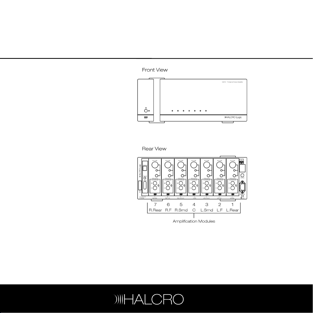
MC70
7 Channel Power Amplifier
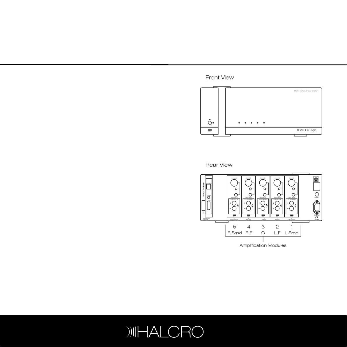
MC50
5 Channel Power Amplifier
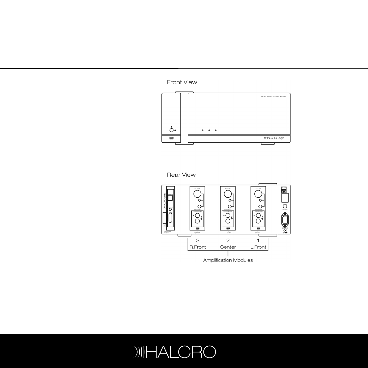
MC30
3 Channel Power Amplifier
MC20
2 Channel Power Amplifier
www.halcro.com

1
Contents
Introduction................................................3
Important Safety Information...................5
Symbols ......................................................... 5
Electrical safety............................................. 5
Protection from fluids .................................. 6
Service warnings.......................................... 6
Protection from overheating .......................7
Additional Important Safety Instructions for
US ................................................................... 8
Interference warning - US FCC Regulations
........................................................................ 9
Wiring to the Loudspeaker Terminals to
Class 2 Wiring (US Wiring Regulations)..... 9
For Consumers within the EU: .................. 10
MC20 Features ........................................11
MC30 Features .......................................12
MC50 Features .......................................13
MC70 Features........................................ 14
Installation................................................. 15
Unpacking .................................................... 15
Storing packaging .......................................15
Positioning....................................................15
Controls and Connections..................... 17
Front panel ................................................... 18
Rear panel ....................................................18
MC20/30/50/70 inputs..............................19
Connecting loudspeakers ......................... 19
Connecting an audio source..................... 21
Connecting a processor ........................... 22
Connecting the trigger .............................. 23
Connecting to a PC ................................... 23
Connecting the mains supply cable........ 23
Break-in period........................................... 23
Operation................................................. 25
Starting up................................................... 25
Shutting down ............................................ 25
Care and Maintenance.......................... 27
Cleaning....................................................... 27
Troubleshooting .....................................29
Halcro Reliabilty Assurance Service
(HRAS) ......................................................31
Installing HRAS Monitor software ............. 31
Launching HRAS Monitor ......................... 32
Setting up HRAS Monitor.......................... 32
Viewing the events log............................... 41
Shutting down HRAS Monitor .................. 42
Uninstalling HRAS Monitor........................ 42
Communications .................................... 43
Setting the IP address ............................... 43
Ethernet communications........................ 43
Serial communications.............................. 43
Service and Warranty Information ....... 47
Overview ..................................................... 47
Product warranty ....................................... 47
Exclusions to the warranty ....................... 47
Transferability.............................................. 48
Warranty verification.................................. 48
Warranty registration................................. 48
If service is required................................... 48
Transportation of products ...................... 49
Freight damage claims.............................. 49
If you have moved ..................................... 49
Thank you for choosing Halcro!............... 49
Index..........................................................51

2

3
Introduction
Congratulations on purchasing the Halcro
Logic MC20, MC30, MC50 or MC70 multichannel power amplifier.
Born from a decade of high-performance
two-channel Research and Development that
produced the world’s finest super-high-end
amplification systems, comes home theater at
the highest level.
Halcro Logic provides unprecedented levels
of leading technology, resulting in reliability and
Super-Definition performance.
Halcro Logic is used throughout the world by
home theater connoisseurs with a genuine
love and passion for home entertainment at its
best.
Halcro has enjoyed creating perfect audio
reproduction for the world's music
connoisseurs.
Please enjoy the Halcro Logic audio
experience.
If you wish to contact Halcro to give us
feedback on your purchase or for general
enquiries, please feel free to:
E-mail us at:
or phone: +61 8 8238 0807.
admin@halcro.com
Amplification for your home theater system
must meet a stringent set of requirements. It
must have a dynamic range to suit the most
explosive action, the subtlest of tender
moments and all that lies between. It must not
distract with any intrusive distortion, and it
must deliver all of this with pinpoint timing and
accuracy.
Each Halcro Logic multi-channel amplifier is a
powerhouse that responds precisely to each
of these demands, utilizing LYRUS™
technology to ensure the maximum detail and
impact is drawn from all soundtracks.
LYRUS™ amplification technology was
developed by Bruce Candy, one of the
world's leading commercial physicists and a
passionate audiophile. LYRUS™ is the only
genuine high-performance Class D
amplification technology on the world market.
It delivers very low levels of Total Harmonic
Distortion (THD), the key feature of the Halcro
range of monoblock and stereo amplifiers.

4
5
Important Safety Information
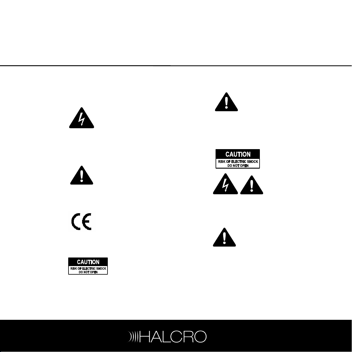
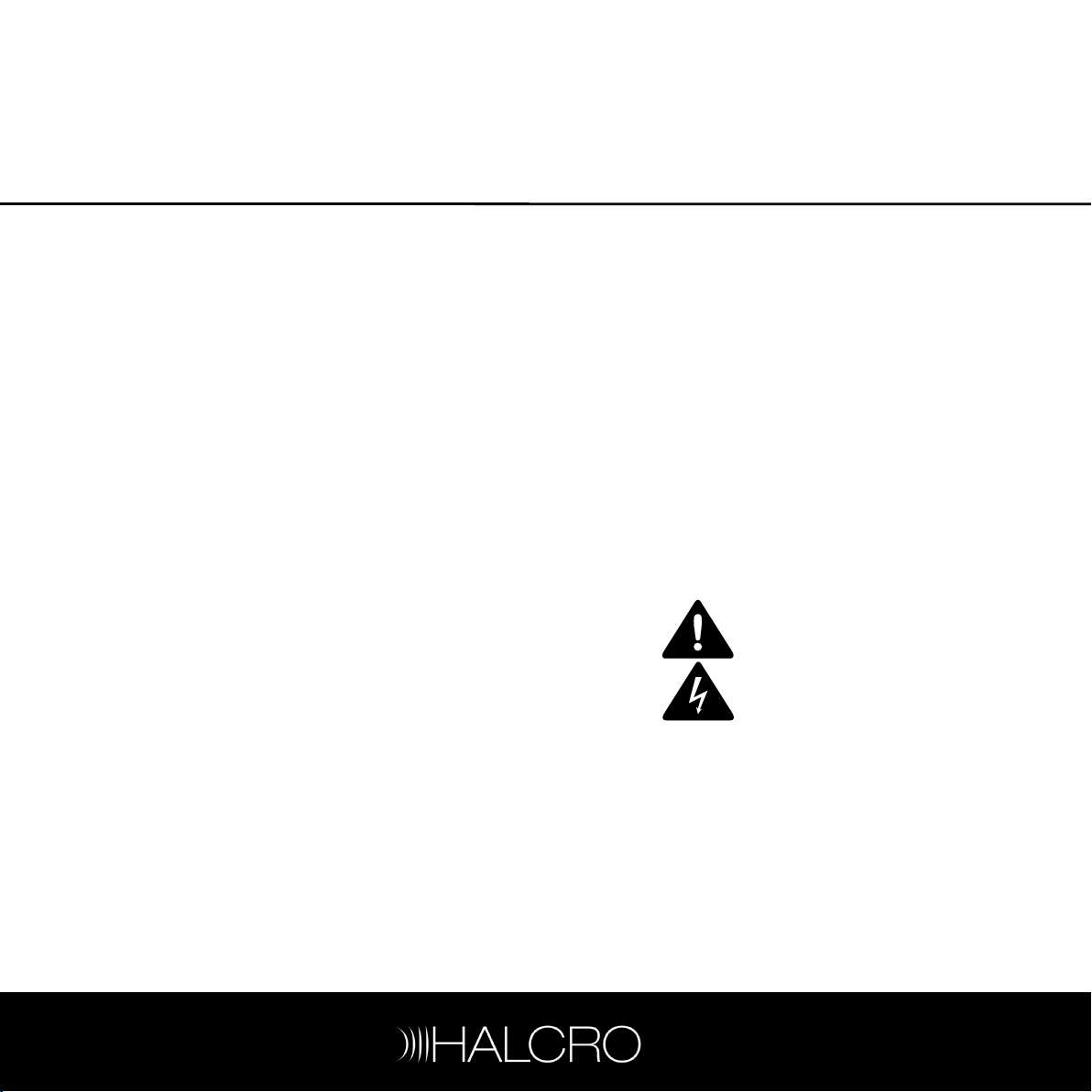
Symbols
The following symbols are used on this
equipment:
The lightning flash with
arrowhead symbol, within an
equilateral triangle, is intended to
alert the user to the presence of
uninsulated ‘hazardous voltage’
that may be of sufficient
magnitude to constitute a risk of
electric shock to a person if
exposed or contacted
The exclamation point within an
equilateral triangle is intended to
alert the user to the presence of
important operating and
maintenance (servicing)
instructions in the following
pages.
The ‘CE’ symbol indicates
compliance of this device with
the relevant directives of the
European community including
the EMC (Electromagnetic
Compatibility) and LVD (Low
Voltage Directive) standards.
Warning of electrical shock
hazard. Do not open cover
(or back). There are no user
serviceable parts inside.
Refer servicing to qualified
service personnel.
.
Electrical safety
WARNING: This product must
always be connected to a
mains socket outlet with a
protective earth connection
Only use a suitable approved mains cord
complying with European individual country
requirements in the CE Low Voltage Directive
Scheme.
DANGER: Do no
open the cover o
back, or remove any
panels, or try to
modify or repair the
MC20/30/50/70.
Opening the
MC20/30/50/70 may
expose you to
dangerous voltages
and will void the
warranty.
WARNING: The Standby/On
button does not disconnect the
unit from the mains power.
To disconnect the unit from the
mains, switch off the unit at the
mains socket outlet and
withdraw the mains plug from
the socket outlet
.
.
t
r
6
The unit should be installed in a position where
the mains plug is easily accessible. Disconnect
the unit from the mains if it is to be left unused
for a long period.
WARNING: No naked flame
sources, such as lighted
candles, should be placed on
the unit.
If naked flame sources tip over
they could resul in a fire.t
Protection from fluids
The Halcro Logic MC20/30/50/70 units are
designed for indoor use only and are not
protected against liquids. They must not be
exposed to dripping or splashing and no
objects filled with liquids, such as vases,
should be placed on them.
If liquid is accidentally spilled on the device,
immediately disconnect the unit from the
mains. Allow sufficient time for complete
evaporation before using the MC20/30/50/70
again. If the liquid is anything other than water,
do not use the device before a qualified
service technician has examined it.
Cleaning may be performed with a slightly
damp cloth that has been wrung until nearly
dry. Refer to the section on
page 27.
Cleaning
on
WARNING: To reduce the risk
of fire or electric shock, do not
expose this equipment to rain
or moisture.
Do not allow liquids to enter
the unit or contact electrical
terminals.
Service warnings
All compartments are sealed at the factory. If
the seals are broken, the warranty will be void
and all service costs will be charged to the
owner.
DANGER: Contains no use
serviceable parts. Do not
attempt to open any of the
MC20/30/50/70
compartments as this may
expose you to dangerous
voltages and will void the
warranty.
r

7
Requires F 10A L 250V fuse for continued
protection against the risk of fire. Never
bypass or use any other type of fuse. The fuse
is located on the rear panel of the multichannel power amplifier (13).
WARNING: Always replace the
fuse with the same type and
rating as specified:
F10AL250V.
Always disconnect the unit
from the mains before
touching the loudspeaker
terminals or replacing the fuse.
Protection from overheating
The MC20/30/50/70 generates a certain
amount of heat and requires ventilation. Slots
and ventilation holes are provided for
ventilation purposes, and to ensure reliable
operation of the product. To prevent fire
hazards, these openings must never be
blocked or covered.
The MC20/30/50/70 may be stacked on top
of a Halcro Logic SSP80/100 amplifier but
overheating may result if ventilation is
inadequate. Ensure there is at least 4 in
(10 cm) above the uppermost unit for
ventilation.
Follow the precautions listed below. If these
precautions are not followed, overheating or
failure may result. Overheating also shortens
the working life of all components.
• do not block the ventilation holes in the
top or bottom of the unit with any object,
including paper, cloths or curtains
• do not place the unit on a soft surface
such as a rug, or carpet with a thick pile,
into which it could sink
• avoid placing the unit in a built-in
installation place such as a bookcase or a
rack unless you can provide proper
ventilation
• do not operate the unit inside a cabinet
unless it has adequate ventilation (such
as an open back panel)
• allow at least 4 in (10 cm) on all sides of
the unit (except the bottom)
WARNING: Do not obstruct
ventilation slots in the chassis.

8
Additional Important Safety Instructions for US
The following instructions should be followed
by customers in the USA in addition to the
safety instructions in the rest of this chapter:
o Read these instructions.
o Keep these instructions.
o Heed all warnings.
o Follow all instructions.
o Do not use this apparatus near water.
o Clean only with dry cloth or according to
the cleaning instructions.
o Do not block any ventilation openings.
o Install in accordance with the
manufacturer’s instructions.
o Do not install near any heat sources such
as radiators, heat registers, stoves, or
other apparatus (including amplifiers) that
produce heat.
o Do not defeat the safety purpose of the
polarized or grounding-type plug.
A polarized plug has two blades, with one
wider than the other. A grounding type
plug has two blades and a third
grounding prong. The wide blade or the
third prong is provided for your safety. If
the provided plug does not fit into your
outlet, consult an electrician for
replacement of the obsolete outlet.
Additional instructions continued:
o Protect the power cord from being
walked on or pinched particularly at
plugs, convenience receptacles, and the
point where they exit from the apparatus.
o Only use attachments/accessories
specified by the manufacturer.
o Unplug this apparatus during lightning
storms or when unused for long periods
of time.
o Refer all servicing to qualified service
personnel.
Servicing is required when the apparatus
has been damaged in any way, such as if
the power-supply cord or plug is
damaged, liquid has been spilled, or
objects have fallen into the apparatus, if
the apparatus has been exposed to rain
or moisture, does not operate normally,
or has been dropped.

9
Interference warning - US
FCC Regulations
This equipment has been tested and found to
comply with the limits for a Class B digital
device, pursuant to part 15 of the FCC Rules.
These limits are designed to provide
reasonable protection against harmful
interference in a residential installation. This
equipment generates, uses, and can radiate
radio frequency energy and, if not installed
and used in accordance with the instructions,
may cause harmful interference to radio
communications. However, there is no
guarantee that interference will not occur in a
particular installation.
If this equipment does cause harmful
interference to radio or television reception,
which can be determined by turning the
equipment off and on, the user is encouraged
to try to correct the interference by one or
more of the following measures:
o Increase the separation between the
equipment and receiver.
o Connect the equipment into an outlet on
a circuit different from that to which the
amplifier is connected.
o Consult the dealer or an experienced
radio/TV technician for help.
Changes or modifications not expressly
approved by Halcro could void the user's
authority to operate the equipment.
Wiring to the Loudspeaker
Terminals to Class 2 Wiring
(US Wiring Regulations)
This equipment has been classified as having
a Class 2 loudspeaker output requiring wiring
to connect the output terminals to class 2
according to the National Electrical Code.
Consult a qualified installer or electrical
contractor for further information.

10
For Consumers within the European Union:
The following instructions should be followed
by customers in the EU in addition to the
safety instructions in the rest of this chapter:
o Do not dispose of this equipment in
general household waste or unsorted
municipal waste.
The crossed out wheeled bin indicated
on this equipment is an indicator that this
unit should not be disposed of in general
household waste, but recycled in
compliance with local government
regulations or environmental
requirements.
o Please dispose of this equipment via a
recycling service or centre, or by
returning the unit to the local
Minelab/Halcro distributor.
This will enable the equipment to
be disposed of in an environmentally safe
manner.
o Disposal of unwanted waste electronic
equipment in landfilled waste may
contribute to adverse long term
environmental effects due to the leaching
of contaminating and/or toxic substances
contained within some electronic
equipment.
11
MC20 Features
Features of the Halcro Logic MC20 include:
• 2-channel rack mountable or free
standing multi-channel power amplifier
• 400 watts per channel
• unbalanced and balanced voltage inputs
• mains voltage: 100-240 V AC
• remote trigger switch between On and
Standby
• full control via RS232 or ETHERNET
connection
• Command Functions:
switch between On and Standby
ability to inhibit individual amplifier
modules
amplifier module will indicate over-
temperature condition
amplifier module will indicate over-
current condition
Halcro Reliability Assurance Service
(HRAS)
12
MC30 Features
Features of the Halcro Logic MC30 include:
• 3-channel rack mountable or free
standing multi-channel power amplifier
• 400 watts per channel
• unbalanced and balanced voltage inputs
• mains voltage: 100-240 V AC
• remote trigger switch between On and
Standby
• full control via RS232 or ETHERNET
connection
• Command Functions:
switch between On and Standby
ability to inhibit individual amplifier
modules
amplifier module will indicate over-
temperature condition
amplifier module will indicate over-
current condition
Halcro Reliability Assurance Service
(HRAS)
13
MC50 Features
Features of the Halcro Logic MC50 include:
• 5-channel rack mountable or free
standing multi-channel power amplifier
• 350 watts per channel
• unbalanced and balanced voltage inputs
• mains voltage: 100-240 V AC
• remote trigger switch between On and
Standby
• full control via RS232 or ETHERNET
connection
• Command Functions:
switch between On and Standby
ability to inhibit individual amplifier
modules
amplifier module will indicate over-
temperature condition
amplifier module will indicate over-
current condition
Halcro Reliability Assurance Service
(HRAS)
14
MC70 Features
Features of the Halcro Logic MC70 include:
• 7-channel rack mountable or free
standing multi-channel power amplifier
• 350 watts per channel
• unbalanced and balanced voltage inputs
• mains voltage: 100-240 V AC
• remote trigger switch between On and
Standby
• full control via RS232 or ETHERNET
connection
• Command Functions:
switch between On and Standby
ability to inhibit individual amplifier
modules
amplifier module will indicate over-
temperature condition
amplifier module will indicate over-
current condition
Halcro Reliability Assurance Service
(HRAS)
15
Installation
Ensure you have read the Important Safety
Information on page 5, before installing your
Halcro multi channel power amplifier.
If you require assistance in the unpacking and
installation of your Halcro multi channel power
amplifier, please contact your dealer.
Storing packaging
The packaging is custom designed to prevent
damage from occurring during transport.
Store the packaging in a dry location.
Unpacking
Unpack the unit carefully, noting that all
components are present and undamaged.
Your carton should contain the following
items:
• MC20, MC30, MC50 or MC70, as
ordered
• mains supply cable (USA and EU)
• three feet (for stacking)
• Owner’s Manual and Warranty Card
• CD containing HRAS software
Positioning
We suggest that the Halcro multi channel
power amplifier be positioned as near to your
front loudspeakers as practical. The unit
houses several heat sinks that are used to
dissipate heat. The airflow to these should not
be interrupted. Ensure there is at least four
inches (ten centimeters) clearance around the
vents.
Do not connect to mains power
until all the connections are
made and checked.

16

17
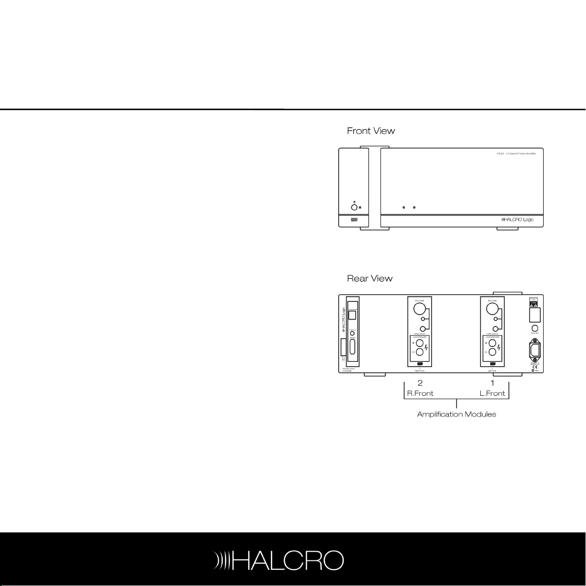
Controls and Connections
The numbers shown on the diagram below
are used throughout the manual to refer to
the individual controls and connections on the
front and rear panel. Refer to this page for a
quick reference to all controls and
connections.

18
Front panel
1 Standby/On button
Switches the multi-channel power
amplifier between Standby and ON.
2 Power LED
LED indicating the unit is in Standby
mode.
3 Amplifier s atus indicators
LEDs indicating the status of the amplifier
modules.
t
Rear panel
4 Communications card
RS232, trigger and Ethernet connections
to computers or home automation
systems or control center.
5 Ethernet connection
Connects to a PC.
6 Trigger connection
Connects to a control center such as the
Halcro Logic SSP80/100 to allow it to
control the multi-channel power amplifier.
7 RS232 connection
Interface for connection to a home
automation system or computer
network.
8 Balanced voltage input
Connects to an audio source such as a
CD player.
9 Selector switch
Selects balanced or unbalanced voltage
input.
10 Unbalanced voltage input
Connects to an audio source such as a
CD player.
11 Loudspeaker connections
Positive and negative loudspeaker
connections (maximum of seven in the
MC70).
t
12 Master On/Off swi ch
13 Fuse
14 Mains inlet socket
15 Amplification modules
Connections to up to seven (in the
MC70) amplification modules comprising
audio input and loudspeaker connections

19
MC20/30/50/70 inputs
Connect the audio source to the required
input, and make sure the selector switch is in
the correct position: up for balanced voltage
input; down for unbalanced voltage input.
Balanced voltage input:
High impedance: suitable for a standard
preamplifier or CD player for example. XLR
output.
Input impedance: 10 kohms + 10 kohms.
Unbalanced voltage input:
High impedance: suitable for a standard
preamplifier or CD player for example. RCA
output.
Input impedance: 10 kohms.
Connecting loudspeakers
There may be voltages
present at the loudspeaker
terminals which may present
an electric shock hazard if
touched. Always ensure the
unit is switched to OFF or
Standby mode when
connecting or disconnecting
loudspeakers.
,
Each amplification module is numbered and
named (15) for your convenience. To ensure
peak performance, and share the load equally
between the power supplies, we recommend
you connect the speakers as designated by
name. For example, connect the Left Front
speaker cable to 'L.Front' on your
MC20/30/50/70. (Refer to the diagram on
following page.)
Each amplification module has two
loudspeaker terminals (11):
• Positive + (red)
• Negative - (black)
To connect the loudspeakers, connect the
positive (red) terminal of the multi-channel
power amplifier to the positive (red) terminal of
the designated loudspeaker. This will ensure
correct phasing of the audio signal. We
recommend only one loudspeaker be
connected to each amplifier module. Ensure
the loudspeaker terminals are securely
tightened, but do not over-tighten to the point
of damaging the connection.
Use only loudspeaker cables with wellinsulated terminals.
DO NOT SHORT-CIRCUIT THE TERMINALS.

20
Connecting loudspeakers

Connecting an audio source
Each amplifier module has two switchselectable inputs with an associated input
socket for connection to the audio source
such as a CD player). The input sockets (8
and 10) and switch (9) are on the rear panel
and the switch must be set to the required
21
input. Make sure the speaker setup is
consistent. For example, make sure the ‘Right
Front’ speaker is connected to the ‘Right
Front’ amplification module that in turn is
connected to the ‘Right Front’ output of the
source.

22
Connecting a processor
Connect either the balanced (8) or
unbalanced (10) inputs on the multi channel
power amplifier to the processor, making sure
the speaker setup is aligned. For example,
connect module 7 (Right Rear) of the amplifier
to the corresponding ‘R.Rear’ output on the
processor. Make sure you set the selector
switch (9) on the rear panel to either balanced
or unbalanced as per you connections.

23
Connecting the trigger
Your MC20/30/50/70 can be turned on
remotely from Standby mode if it is connected
by trigger cable to a control center such as
the Halcro Logic SSP80/100. To activate the
remote On/Standby function:
o Locate a suitable trigger cable.
recommended is a maximum length of
three meters of shielded cable. Lengths
longer than this and/or the use of
unshielded cable may result in radio
interference issues.
o Connect the cable from the trigger input
(6) on the multi-channel power amplifier
to the trigger output on the control center
(SSP).
When connected by trigger
cable, the MC20/30/50/70
cannot be switched to
Standby by selecting the
Standby/On button.
If you require more information, please
contact
your dealer.
The
Connecting to a PC
The MC series of multi-channel power
amplifiers can be connected to a PC or
Network. To connect to the PC/Network:
o Locate a suitable Ethernet cable (cross-
over cable required for direct PC to MC
unit connections).
o Connect the cable from the Ethernet
input (7) on the multi-channel power
amplifier to the computer's Ethernet
adaptor.
Connecting the mains supply cable
Connect the mains supply cable into the unit's
socket (14), which is positioned, at the rear of
the unit.
Continue to read the following pages before
connecting to the mains outlet.
Break-in period
The multi-channel power amplifier electronic
break-in period is completed at the factory. A
further break-in period is not required.

24

25
Operation
Numbers in this chapter refer to the
controls and connections diagram on
page 17.
Starting up
Once the external cables are connected to
the units, ensure the Master On/Off switch
(12) is in the Off position, and then operate the
system as follows:
o Plug the mains cable into a mains
outlet.
o Turn on the mains
o Switch the Master On/Off switch on the
rear panel, to ON (12).
After a brief initialization sequence, as
displayed on the front panel LEDs, the power
LED (2) will glow red, which indicates the unit
is in Standby mode. In this mode a small
current is drawn from the mains supply, but
the unit cannot drive the loudspeakers.
o Press the Standby/On mode button (1)
once to switch between Standby and On
modes.
In ON mode, the LEDs (3) on the front panel
glow blue to show the unit is active. (When
switching from Standby to On, some amplifier
module LEDs may briefly flash red before
operating a steady blue. This is normal
operation.)
socket outlet switch.
socket
The multi-channel power amplifier is now
ready to drive your loudspeakers.
If the multi-channel power amplifier trigger
(6) is connected to a con rol center sucht
as the Halcro Logic SSP, it can be left in
Standby mode since the con rol cen er will t t
operate the amplifier when required.
Shutting down
It is safer to turn the mains power off when not
using the multi channel power amplifier for
extended periods. However the MC unit may
be left in Standby mode for periods between
active use. Select the Standby/On button to
toggle between Standby and On.
To turn the unit off, switch the master On/Off
switch (12), and then switch off and/or
disconnect from the mains at the socket
outlet.
The multi-channel power amplifier has a very
short warm up period when turned on again.
If the unit is connected via the
trigger input (6) to a control
center (SSP the unit cannot
be switched to Standby mode
using the Standby/On button
),

26

27
Care and Maintenance
The multi channel power amplifiers have been
designed for indoor use only. Under no
circumstances should the amplifier be allowed
to get wet. The only maintenance required is
to ensure the unit is kept clean.
Cleaning
Halcro takes no responsibility for any damage
caused through careless or improper cleaning
techniques.
WARN NG: Never use flammable
I
p oducts when cleaning the
r
MC20/30/50/70 as this may
damage the surface finish of the
product.
Please read the following procedures very
carefully:
o Before cleaning, disconnect the unit from
the mains supply.
Use only extremely soft cloths.
o Use a soft dry cloth to remove any dust.
o Add 0.5 fl oz (15 ml) of very mild
household dishwashing detergent to a
one-gallon (four-liter) bucket of tepid
water.
o Immerse the soft cloth in the bucket of
water and then wring the cloth out
thoroughly until the cloth is nearly dry.
o Use the slightly damp cloth to clean the
unit surfaces.
Never clean any electrical fittings or
terminals with the damp cloth.
o After using the slightly damp cloth, wipe
over the surfaces with a soft dry cloth.
o Allow the amplifier to air for at least one
hour before turning the power back on.
If you are unsure about the cleaning of the
amplifier and require more information, please
ask your dealer or contact Halcro at:
service@halcro.com

28

Troubleshooting
Symptom Remedy
NO sound and NO lights Ensure the master switch is On and the mains cable is plugged
into the multi-channel power amplifier.
Ensure the mains cable is plugged into a working wall socket.
(Try testing the wall socket with another appliance.)
Check the fuse.
NO sound and a RED Light Press the Standby / ON button to select ON.
29
NO sound and all lights are
BLUE
NO sound or sound missing
from one or more
loudspeakers, the power light
is BLUE and one or more amp
lights FLASH RED
NO sound or sound missing
from one or more
loudspeakers, the power light
is BLUE and one or more amp
lights are RED
NO sound or sound missing
from one or more
loudspeakers, the power light
is BLUE, and one or more amp
lights are OFF
Ensure the input selector switch is set to the correct input.
Ensure loudspeaker cables are correctly connected (both ends).
Ensure the input cables are correctly connected (both ends).
Try a different audio source.
Try a different loudspeaker.
Amplifier module is too hot. Wait for it to cool and try again.
Speaker terminals short-circuited.
Major failure in amplifier module.
Check, using HRAS, if any modules have been set to OFF (see
page 40). If so, reset the modules to ON as required.

30

Halcro Reliabilty Assurance Service (HRAS)
31
The Halcro Reliability Assurance Service
(HRAS) is an optional feature that may be
installed on a computer connected to your
home entertainment network. If installed and
running, HRAS monitors the performance of
the system. It can be set up to alert your
dealer, installer, or yourself by E-mail if any
amplification module fails, without disruption to
your listening pleasure. An event log can also
be maintained by HRAS for troubleshooting
purposes.
HRAS is an optional featu e, and the
r
perfo mance of the mul i-channel power r t
amplifier is not compromised if the service
is not installed.
HRAS can dramatically reduce the time taken
to correct faults. The system runs in the
background with no operator actions
required.
Installing HRAS Monitor software
To install and run HRAS, you must have a
personal computer (PC) with:
• Microsoft Windows
• CD ROM drive
The person ins alling the HRAS software t
must have administrator rights on the PC.
For automatic E-mailing of faults an Internet
connection is required.
®
2000 or later
To install HRAS Monitor on your computer:
o Insert the HRAS CD into your computer
CD drive.
The installation program starts and runs
automatically.
If the installation does not start
automatically, use Windows® Explorer to
view the contents of the CD, then doubleclick the file Setup.exe.
When prompted:
o Click Next (twice), to continue the
installation.
The default destination folder is shown as
C:\Program Files\Halcro\HRAS,
recommend you use this folder unless there is
a valid reason to use a different name and
path.
o Click Next to accept the destination
folder and continue.
o Click Install to install the software.
The installation process takes
only a few moments, at the end
of which a shortcut icon is placed
on the Desktop for easy start up:
When the installation is complete an
Shield Wizard
the installation has been successful.
To launch the application:
o Ensure the
checkbox is ticked.
o Click Finished.
window is displayed, confirming
Launch the Program
and we
Install

32
Launching HRAS Monitor
To launch the application at times other than
during installation:
o Double-click the shortcut icon on the
Desktop.
Note that for users of Windows
Service Pack 2, the following warning
message may appear the first time the
application is launched:
This is a normal warning that appears when
you try to install any program that wishes to
use the communication ports.
o Click Unblock to start the application if
this warning is displayed.
A welcome screen appears for a
few moments, and then an icon
appears on the Windows taskbar to
indicate the HRAS Monitor is active:
®
XP with
If the computer is connected to the Internet,
and an event such as a fault occurs, the fault
is logged, and E-mails are automatically sent
to the recipients listed on the HRAS Monitor
E-mail notification
computer is not connected to the Internet, the
event is logged.
page (see page 35). If the
Setting up HRAS Monitor
To view the
and set up the system:
o Double-click the icon in the
taskbar, OR:
o Right-click the icon and select
Open
The
HRAS Monitor
two pages: one to register devices, and the
other to set E-mail options. A menu bar at the
top offers further functions, including Help in
using the software.
The Edit/Delete/Show Properties and
Show Web Page buttons shown in the
illus ration only become available after at
device is registered and selected in the
Halcro Devices list.
HRAS Monitor
from the menu.
window is displayed. It has
window
The HRAS Monitor application runs in the
background, with no operator actions
required.

33
Registering devices
Devices must be registered with HRAS
Monitor before they can be monitored.
Currently, the only devices monitored by
HRAS are the MC series of multi-channel
power amplifiers.
It is possible to register devices manually (see
page 35), but it is generally easier and quicker
to allow the software to do this automatically.
To allow HRAS Monitor to find and register
devices:
o Make sure HRAS Monitor is running and
the
HRAS Registration
o Make sure your multi-channel power
amplifier is turned on and connected to
the network (as described previously).
o On the
Sear
HRAS Registration
ch Network button.
page is displayed.
page, click the

34
The software begins a search for devices
connected to the network and displays the
results. The name, IP address and status
information should appear automatically.
o Make sure the checkbox in the HRAS
column is checked (click in the box if not)
if you want the device to be monitored.
You can still regis er a device even if it is
t
not to be monitored by HRAS.
When a device is registered and selected,
buttons become available on the right of the
window for editing, deleting or showing
properties of the device. These functions are
also available from the
described on page 39.
Device
menu, and are

Manually registering a device
To register a device manually instead of
allowing the HRAS Monitor to search for
connected components:
o Click Register Device… on the
Registration
The
Register Device
Enter a device name and its IP address in the
boxes, and ensure the check box is ticked if
you want the device to be monitored.
o Click Register to register the device and
return to the
The device should now appear on the list.
page.
dialog is displayed.
HRAS Registration
page.
HRAS
Setting up E-mail notification
HRAS Monitor can send E-mails to up to three
recipients if problems occur with your system.
To setup the E-mail addresses:
o Click the
the
The
E-mail Notification Setup
displayed:
The top section of this page determines
whether E-mail notification is enabled or
disabled.
o To enable E-mail notification, make sure
Enable is checked, as shown:
E-mail Notification Setup
HRAS Monitor
window.
tab on
page is
35

36
To setup which events should trigger an
E-mail (normally failure of an output channel
only).
o Click Select Events.
o Select the checkbox for desired settings
and click OK or simply click OK to accept
the default.
The E-mail Server section of the
Notification
connection details.
o Enter the IP address of your Internet
o Enter “25” at the Port of SMTP server
o Enter the username you use for your
o Enter your full E-mail address.
page sets up your Internet
Service Provider (ISP) (contact your
Internet Service Provider if you are not
sure of the address).
field.
E-mail program to log on to your ISP.
E-mail

37
The bottom section of this page allows you to
enter up to three E-mail addresses. If a
problem occurs with your system, these
E-mail recipients will receive notification of the
problem. Typically the major recipient would
be the Halcro service department, but you
may wish to send an E-mail to the installer,
your Halcro dealer, or even your own E-mail
address.
o Enter at least one E-mail address.
Customizing settings
If you wish, you can customize the E-mail
settings, as follows:
o Click the Advanced… button to view the
Advanced E-mail Settings
o At the top, check the box and insert your
name and telephone details if you want
them included in the E-mail.
o In the bottom section, check the box and
insert the installer’s details if you want
them included in the E-mail.
o Click OK to save the changes, or Cancel
to lose them.
The
E-mail Notification
again.
If you wish, you can send a test E-mail to the
recipient(s) listed at the bottom of this screen.
To do this:
o Click Send Test E-mail.
dialog.
page is displayed
We recommend you telephone the
recipient(s) to confirm they have received the
test E-mail, which will confirm the E-mail setup
is correct. Note: Some Internet service
providers may block the 'alert' E-mails sent by
HRAS.

38
Setting HRAS options
To check or change the HRAS setup options:
o Select Options from the
The
Options
o If a period other than the default is
required, select it from the pull-down list.
o Make sure “Always enable HRAS for
newly discovered devices” is checked, to
ensure any new devices are added
automatically.
o Make sure “Enable logging of HRAS
events” is checked, to ensure events are
logged to aid in troubleshooting.
dialog is displayed.
The oldest events in the log are
automatically deleted when the events log
has reached its set maximum capacity.
o Make sure “Run HRAS Monitor when
Windows
your system is monitored whenever the
computer is turned on.
o Click OK to save the changes, or Cancel
to lose them.
®
starts” is checked, to ensure
Tools
menu.

39
Modifying device properties
To view or monitor a device’s properties:
o On the
the device concerned.
o Click Edit (or select
menu).
The
Edit
o View or change the details as required.
o Click OK to save the changes or Cancel
to lose them.
More details can be viewed by clicking on
Show Web Page.
HRAS Registration
Edit
dialog is displayed.
page, highlight
from the
Device
Viewing or changing device properties
To view or change the properties of a
registered device:
o On the
the device concerned.
o Click the Show Properties… button (or
select from the
The
Prope ties
window has two pages:
Configuration
HRAS Registration
Device
r
window is displayed. This
menu.
General
.
page, highlight
and

40
General
This page indicates the model and serial
number of the device highlighted on the
Registration
and status (on or off) of each of the channels.
In the bottom section the amplifier channel
numbers or PS (power supply) are shown in
red if there is a fault in the respective channel
or power supply.
o Click a button in this section to view more
information of the condition of the
channel or power supply unit.
Configuration
This page can be used to turn individual
amplifier channels on or off. The default is for
all channels to be turned on. To turn one or
more channels off:
o Click the Off button for the channel(s) you
want to turn off.
The Apply button becomes active when you
make a change.
o Click Apply to apply the change to the
device.
o Click Close to close and return to the
HRAS Registration
Clicking Close without clicking Apply first
will lose the changes
window, and shows the mode
page.
.
HRAS

41
Viewing the events log
The events log keeps a record of events
pertaining to the system monitored by the
HRAS application. It is a normal Windows
function.
To view the events log:
o View the
double-clicking the HRAS icon on the
Taskbar.
o Select
menu.
The
Event Viewer
o Click
HRAS Monitor
Event Viewer
window is displayed.
Application
.
window by
from the
®
Tools
To view the HRAS events:
o Click
o Scroll through the list to the HRAS
To view further information on an event:
o Double-click on the event.
The
Source
name.
application events.
Event Properties
to sort the list by application
dialog is displayed.

42
Shutting down HRAS Monitor
To exit the HRAS Monitor
program, right click the HRAS
application icon in the Windows
Taskbar, and then select
from the menu.
Note that closing the HRAS
Monitor window does not shut down the
application. If the icon is present on the
Toolbar, the HRAS Monitor is still running.
Exit
®
Uninstalling HRAS Monitor
If you need to uninstall HRAS Monitor for any
reason, proceed as follows:
o Shut down the HRAS Monitor if it is
running (refer to previous section).
o Click the Windows
o Select
Settings / Control Panel / Add or
Remove Programs
A list of installed programs is displayed.
®
Start button.
.
To remove the application:
o Scroll through the list to find and select
HRAS Monitor
o Click Remove.
o Click Yes on the warning dialog to
confirm you do wish to uninstall the
program.
o Close the window.
.
As with any other software, do
not try to uninstall the program
by just deleting it.
It is important to remove it as
described above, or your
computer’s operating system
could become unstable.

43
Communications
The Halcro MC series have can be controlled
and monitored via a personal computer (PC).
A serial and an Ethernet port are available for
this purpose.
Each port has two modes of operation: plain
ASCII and pseudo-binary. In ASCII mode
commands and messages are sent as plain
text. In pseudo-binary mode commands and
messages are encoded.
Setting the IP address
The IP address can be manually setup or
automatically assigned by a DHCP server on
the network, depending on the DHCP state of
the amplifier.
If DCHP is set to ‘never’ an IP address and
netmask must be assigned via the serial port.
If DHCP is set to ‘auto’ and an IP address has
been assigned manually; you must reset the
IP address to 0.0.0.0 then the DHCP sever will
assign a new address at next start up.
If DHCP is set to ‘always’ a new IP address will
be obtained at start up.
If an IP address is set by DHCP the easiest
way to determine the number is to use the
Halcro HRAS software. This will communicate
with any Halcro equipment on the network via
UDP and report the IP addresses found. For
more information on HRAS software please
see page 31.
Ethernet communications
The multi-channel amplifiers can be
connected to an Ethernet network. There are
three modes of communication which
operate on different ports:
• port 60001 is Pseudo-binary on TCP/IP
• port 60002 is ASCII on TCP/IP
• port 60003 is UDP/IP
HyperTerminal can be used to communicate
with a multi-channel power amplifier.
The commands are the same as for the serial
communications.
Serial communications
Almost any terminal program can be used on
a PC to communicate with a multi-channel
power amplifier. Windows provides a tool
called HyperTerminal, which can be used for
this purpose.
The settings for serial communications are:
Speed: 38400 bps
Data bits: 8
Parity: None
Stop bits: 1
Flow control: Hardware
When first connected to the amplifier via the
serial port, communications are in pseudobinary mode.

44
The commands are as follows:
*m=xx set amplifier enable
bitmask to hex value
*m? print current amplifier
enable mask in hex
*p0 power off (standby)
*p1 power on
*s? status query
LF LF LF exit to ASCII mode
The status message is in the form:
*S!:M0xRxxxxxxxPxVxxxxAxxxxxxxTxxxxx
xxCxxxxxxxDxxxxxxxFxxxxxxxHxxxxxxx
where:
*S!: indicates a message sent
from the amplifier as a
result of an error.
*S?: Indicates a message sent
as a response to a request
for status query.
M0x indicates model number,
M01 = MC20, M02 =
MC30, M03 = MC50 and
M04 = MC70.
Rxxxxxxxx indicates serial number of
amplifier
Px indicates power status, 1 =
On, 0 = Standby
Vxxxx indicates the status of the
power supplies in the order
–5V, +12V, +72Va, +72Vb.
0= off, 1 = on
Axxxxxxx indicates which amplifier
modules are active, 0 = not
active, 1 = active
Txxxxxxx indicates the temperature
status amplifier modules, 1
= OK, 0 = Over
temperature
Cxxxxxxx indicates the load status of
amplifier modules, 1 = OK, 0
= Over current
Dxxxxxxx indicates the operational
status of the amplifier
modules, 1 = OK, 0 = Faulty
Fxxxxxxx indicates the operational
status of the fans, 1 = OK 0
= Faulty
Hxxxxxxx indicates the time in
minutes the amplifier has
been in power On mode.
This does not include time
spent in standby.

45
To enter ASCII mode press return three times
to send three line feeds. Once in ASCII mode
you cannot return to pseudo-binary mode
without disconnecting and reconnecting. The
ASCII commands are as follows:
help print list of commands
version print firmware version
information
status print status information
on enter full-power mode
standby enter standby mode
off enter standby mode
serial print amplifier serial number
model print amplifier model
hours print total hours run
enable print current amplifier
enable mask in hex
enable xx set amplifier enable
bitmask to hex value
set print settings
set ethernet <addr> print or set IP
address
set ip <addr> print or set IP address
set netmask <addr> print or set netmask
set broadcast <addr> print or set
broadcast address
set gateway <addr> print or set gateway
set dhcp <state> print or
enable/disable DHCP
net show active settings
net reload apply new settings
exit disconnect
Valid states for DHCP are: always, never auto.
Once a change to the network settings has
been made, such IP address or DHCP state,
the command ‘net reload’ must be issued for
these changes to take effect.

46

47
Service and Warranty Information
Overview
All Halcro products are designed and built to
world-class standards of quality, reliability, and
performance. Since so much care has gone
into our products, we are able to offer a
strong warranty that protects your investment
in Halcro products for years to come. It is our
expressed desire that your Halcro products
work flawlessly and that you enjoy music,
movies, and audio/video entertainment
without interruption or compromise to
performance.
It is the goal of Halcro Customer Service to
provide efficient and timely service to Halcro
owners and to our dealers. In the event of a
technical problem or failure, we will work with
you and your authorized Halcro dealer to
minimize down time and provide expedient
service to remedy the situation. We suggest
that your Halcro dealer be the first point of
contact should you experience any problems.
Solutions are often simple and can be handled
in the field.
Please do not attempt to open up sealed
compartments on any Halcro products.
Product warranty
Halcro warrants the MC20, MC30, MC50 and
MC70 multi-channel power amplifiers to be
free from defects in materials and
workmanship for a period of three years from
the original date of purchase. During the
warranty period, Halcro will remedy all such
defects without charge for parts or labor.
Exclusions to the warranty
This warranty does not extend to damage
resulting from improper installation or setup,
misuse, neglect, or abuse. Changes in the
appearance of the product resulting from
normal wear and tear, moisture, or
atmospheric conditions are not warranted.
The warranty shall be void and of no effect if
any of the following occur:
• the defect has resulted from improper,
unreasonable, or negligent use
• the defect is a result of accident,
tampering, alteration, or modification
• the defect is a result of improper
installation or setup by a third party
• the unit's serial number has been
removed, altered, or made illegible
• Halcro is not liable for incidental or
consequential damage of any kind
• Halcro does not warrant system design
or installation

48
Transferability
Transferability means that the warranty stays
with the product from the date of original
purchase through the full warranty period,
regardless of who owns the product.
The Halcro warranty is transferable, providing
that the original sales receipt or proof of
purchase is supplied to both subsequent
owners and to Halcro when ownership
changes.
Warranty verification
It is the owner's responsibility to show proof or
purchase verifying that the unit to be serviced
is within the warranty period. Proof of
purchase options include:
• copy of sales receipt showing name of
original owner, dealer, and purchase date
• copy of credit card voucher or cancelled
check accompanied by owner's record
of purchase date and serial number
Warranty registration
While not required for service, we request that
you register your Halcro product as soon as
you purchase it. Please use the Halcro
Product Warranty Registration form that is
provided or request a copy from your Halcro
dealer.
If service is required
We suggest that you work with your
authorized Halcro dealer when the need for
technical service, training, or applications
advice arises.
service or repair, your product should be
shipped to Halcro or your authorized Halcro
dealer to be returned to the factory for
service.
the following conditions must be met:
To qualify for free warranty service,
• the unit must be returned to Halcro or its
authorized repair center in the original
packing materials
This will ensure the safety of the
equipment. If you have misplaced or
damaged the original packaging, you can
purchase new packaging through your
dealer or directly from Halcro.
• the unit must be accompanied by a copy
of the Halcro Product Warranty
Registration card and the original sales
receipt
• shipments to Halcro must include a
Return Authorization number
To obtain this authorization, please ask
your dealer or email Halcro directly (see
contact information below).
• Halcro cannot be responsible for any
damage caused to your equipment
during shipping due to improper
packaging
If the packaging material needs to be
replaced on its arrival at the factory, the
owner will be informed of the
replacement cost.
If your Halcro product requires

49
Transportation of products
Halcro pays freight one-way to return product
once warranty repair is completed. Halcro
requests prepaid shipment to the factory or to
a designated repair center or service agency.
We are not equipped to accept freight collect
shipments.
Halcro is not liable for freight, courier, or other
charges incurred in transporting a unit to and
from a dealership, service center, or the
factory unless written approval and
instructions are issued in advance. Such
documents must include the Halcro Return
Authorization number, a detailed description
of the situation, and signature of authorized
Halcro representative.
Freight damage claims
If a unit being returned to Halcro is damaged
in shipment, Halcro will contact the carrier for
inspection. The carrier will contact the shipper
regarding the claim. Halcro is not liable for
damage or delays caused in shipment to or
from Halcro facilities.
If you have moved
In the event that you have changed locations
since your original Halcro purchase, we will
happily direct you to your nearest authorized
Halcro dealer upon request.
Thank you for choosing Halcro!
We trust you will enjoy the performance of
your Halcro equipment long past the warranty
period. Thank you for choosing Halcro!

50

Index
51
7.1 output, 21
Audio input, 21
Balanced voltage input, 19
Break-in, 23
CE mark, 5
Communications, 43
Computer requirements, 31
Control center, 21
Customizing settings, 37
Device properties, 39
Electronics break-in, 23
E-mail, 3, 31
notification, 32, 35
EMC, 5
Ethernet, 43
EU, 10
Events viewer, 41
Fault finding, 29
FCC rules, 9
Feedback, 3
Fuse, 7
Halcro SSP, 21
HRAS, 31
customizing, 37
device registration, 33
E-mail notification, 35
events log, 41
installing, 31
launching, 32
manual registration, 35
monitor, 32
options, 38
setting up, 32
shut down, 42
starting, 32
uninstalling, 42
Impedance, 19
Interference, 9
Introduction, 3
IP address, 43
LED, 25
Lightning, 8
Lights, 29
Liquids, 6
Location of components, 18
LVD, 5
Master On/Off switch, 25
MC20, 11
MC30, 12
MC50, 13
MC70, 14
Naked flames, 6
On mode, 25
Operation, 25
Overheating, 7
Packaging, 15, 31
replacement, 31
Packing list, 15
Polarized plug, 8
RCA output, 19
Register devices, 33, 35
Return authorization, 48
Safety, 5
Service
warnings, 28
Servicing, 8
Software, 31
SSP, 21
Standby mode, 25
Start up, 25
Symbols, 5

52
Test E-mail, 37
Troubleshooting, 29
Unbalanced voltage input, 19
Uninstall, 42
Unpacking, 15
US warnings, 8
Ventilation, 7
Voided warranty, 47
Warm up, 25
Warranty, 47
XLR output, 19

53

54
Copyright and acknowledgements
This product is manufactured by Extraordinary Technology (Hi-Fi) Pty Ltd trading as Halcro and
Halcro Audio (USA) Inc
Halcro Logic and Lyrus are trademarks of Extraordinary Technology (Hi-Fi) Pty Ltd,
Australia.
Microsoft
®
and Windows® are trademarks of Microsoft Corporation, USA.
Halcro Logic MC20/30/50/70 Owner’s Manual Revision 2.1, © Halcro 2005
 Loading...