

Page 1
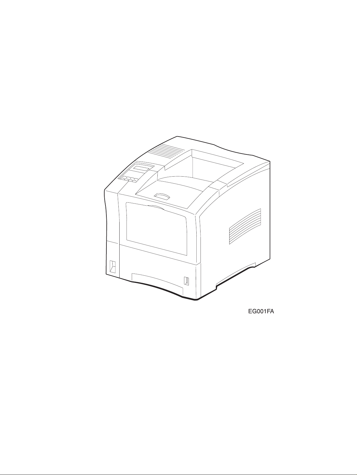
HAKUBA
26PPM Laser Printer
Base Engine Technical Manual
Version 1.0
Page 2

NOTICE
The information in this guide is subject to change without notice.
XEROX INTERNATIONAL PARTNERS SHALL NOT BE LIABLE FOR TECHNICAL OR EDITO-
RIAL ERRORS OR OMISSIONS CONTAINED HEREIN; NOR FOR INCIDENTAL OR CONSEQUENTIAL DAMAGES RESULTING FROM THE FURNISHING, PERFORMANCE, OR USE OF
THIS MATERIAL.
This guide contains information protected by copyright. No part of this guide may be photocopied or reproduced in any form without prior written consent from Xerox International Partners.
Page 3

FEDERAL COMMUNICATIONS COMMISSION NOTICE
This equipment has been tested and found to comply with the limits for a Class B digital device,
pursuant to Part 15 of the FCC Rules. These limits are designed to provide reasonable protection against harmful interference in a commercial installation. This equipment generates, uses,
and can radiate radio frequency energy and, if not installed and used in accordance with the
instruction, may cause harmful interference to radio communications. However there is no guarantee that interference will not occur in a particular installation. If this equipment does cause
harmful interference to radio or television reception, which can be determined by turning the
equipment off and on, the user is encouraged to try to correct the interference by one or more of
the following measures:
• Re–orient or relocate the receiving antenna
• Increase the separation between the equipment and receiver
• Connect the equipment into an outlet on a circuit different from that to which the receiver is
connected
• Consult the dealer or an experienced radio/television technician for help.
The user may find the following booklet prepared by the Federal
Communications Commission helpful:
“How to Identify and Resolve Radio-TV Interference Problems”. This booklet is available from
the U.S. Government Printing Office, Washington D.C. 20402, Stock No. 004-000-00345-4.
Modifications
Changes or modifications to this equipment not expressly approved
by Xerox International Partners may void the user's right to
operate the equipment.
Page 4

CANADIAN NOTICE
This digital apparatus does not exceed the Class B limits for radio noise emissions from digital
apparatus set out in the Radio interference regulations of the Canadian Department of Communications.
AVIS CANADIEN
Cet appareil numerique est conforme aux limites émission de bruits radioélectriques pour les
appareils de classe B stipulés das le réglement sur le brouillage radioéletrique du Ministére des
Communcations du Canada.
EUROPEAN NOTICE
This equipment has been tested and determined to be compliant with VDE requirements for a
Class B device.
HINWEIS
Hiermit wird bescheinigt, dass der Asama Laserdrucker, in bereinstimmung mit den Betimmun-
ngen der Vfg 104ß
Der Deutschen Bundespost wurde das Inverkehrbringen dieses Gertëes angqeigt und die Bere-
chtigung zur berprufung der Serie auf Einhaltung der Bestimmungen eingeräumt.
XEROX INTERNATIONAL PARTNERS
984 funkenstört ist.
Page 5

CLASS 1 LASER PRODUCT
This Laser Printer is certified to comply with laser product performance standards set by the
U.S. Department of Health and Human Services as a Class 1 laser product. This means that this
is a class of laser product that does not emit hazardous laser radiation; this is possible only
because the laser beam is totally enclosed during all modes of customer operation.
The laser and output of the laser scanning unit produces a beam that, if looked into, could
cause eye damage. Service procedures must be followed exactly a written without change.
When servicing the machine or laser module, follow the procedures specified in the manual and
there will be no hazards from the laser.
Use of Controls, adjustments, or performance of procedures other than those specified herein
may result in a hazardous radiation exposure.
Page 6
Unpacking the Base Engine
Be sure to carry the Base Engine by two or more persons taking care to hold it horizontally.
Be sure to take great care for persons not to hurt when carrying it.
Open the package and check the Base Engine for damage in transit.
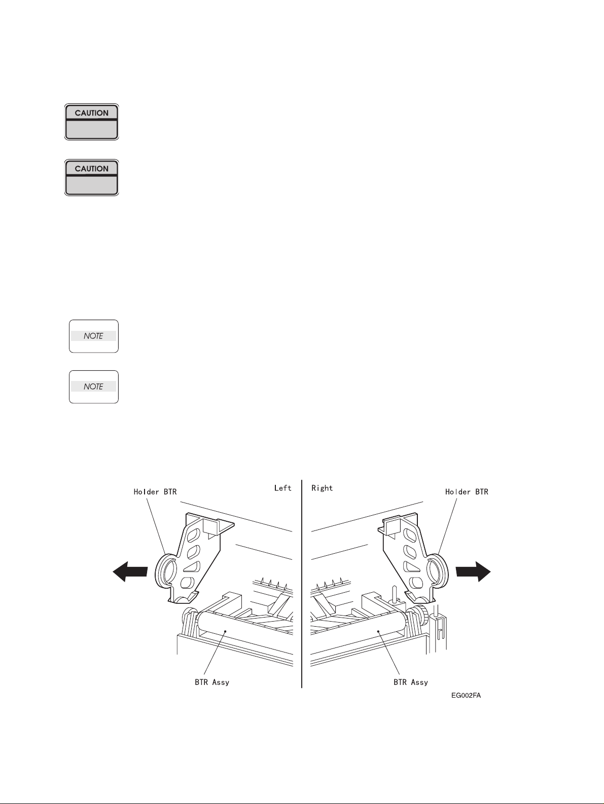
Remove the Holder BTR from the Base Machine after unpacking procedure of Base Engine.
Removal procedure of the Holder BTR is as follows.
1. Open the
2. Catch in the handle of the Holder BTR:L.And pull out the Holder BTR:L from the Base Machine to your
side with diagonal and upper direction.
3. Catch in the handle of the Holder BTR:R.And pull out the Holder BTR:R from the Base Machine to your
side with diagonal and upper direction.
Cover Assy Front
Take care not to give a damage to the Roll surface of the Roll Assy BTR when do the
following procedure.
Holding the Base Machine when do the following procedure.
(PL1.1.9).
Page 7

Contents
Introduction
About this Manual
Safety Information
. . . . . . . . . . . . . . . . . . . . . . . . . . . . . . . . . . . . . . . . . . . . . . . . . . . . . . . . . . . . . . . ix
. . . . . . . . . . . . . . . . . . . . . . . . . . . . . . . . . . . . . . . . . . . . . . . . . . . . . . . . . .x
. . . . . . . . . . . . . . . . . . . . . . . . . . . . . . . . . . . . . . . . . . . . . . . . . . . . . . . . xi
Service Section
1. The Service Flowchart
2. The Fault Isolation Procedure (FIP) Flowchart
3. Primary FIPs: Error Codes
4. Primary FIPs: Printer Performance Problems
5. Primary FIPs: Image Quality Problems
6. Secondary FIPs
. . . . . . . . . . . . . . . . . . . . . . . . . . . . . . . . . . . . . . . . . . . . . . . . . . 6-1
7. Diagnostic Tool and Test Pattern Mode
8. Diagnostic Mode
. . . . . . . . . . . . . . . . . . . . . . . . . . . . . . . . . . . . . . . . . . . . . . . . . 8-1
9. Adjustment Mode
10. Removal and Replacement Procedures
11. Locating P/J Connectors
12. Parts List
. . . . . . . . . . . . . . . . . . . . . . . . . . . . . . . . . . . . . . . . . . . . . . . . . . . . . . . 12-1
. . . . . . . . . . . . . . . . . . . . . . . . . . . . . . . . . . . . . . . . . . . . 7
. . . . . . . . . . . . . . . . . . . . . . . . . . . . . . . . . . . . . . . 3-1
. . . . . . . . . . . . . . . . . . . . . . . . . . . . . . . . . . . . . . . . . . . . . . . . 9-1
. . . . . . . . . . . . . . . . . . . . . . . . . . . . . . . . . . . . . . . . 11-1
. . . . . . . . . . . . . . . . . . . . 2-1
. . . . . . . . . . . . . . . . . . . . . 4-1
. . . . . . . . . . . . . . . . . . . . . . . . . . . 5-1
. . . . . . . . . . . . . . . . . . . . . . . . . . . 7-1
. . . . . . . . . . . . . . . . . . . . . . . . . . 10-1
Technical Reference Section
13. Principles of Operation
14. Wiring Diagrams and Signal Information
15. Printer Specifications
. . . . . . . . . . . . . . . . . . . . . . . . . . . . . . . . . . . . . . . . . 13-1
. . . . . . . . . . . . . . . . . . . . . . . . . . . . . . . . . . . . . . . . . . . 15-1
Optional Equipment Technical Manuals
Option Feeder
Envelope Feeder
Duplex
. . . . . . . . . . . . . . . . . . . . . . . . . . . . . . . . . . . . . . . . . . . . . . . . . . . . . . . . . . . . . DUP-1
Offset Catch Tray
. . . . . . . . . . . . . . . . . . . . . . . . . . . . . . . . . . . . . . . . . . . . . . . . . . . . . TRAY-1
. . . . . . . . . . . . . . . . . . . . . . . . . . . . . . . . . . . . . . . . . . . . . . . . . . . ENV-1
. . . . . . . . . . . . . . . . . . . . . . . . . . . . . . . . . . . . . . . . . . . . . . . . . . . OCT-1
. . . . . . . . . . . . . . . . . . . . . . . . 14-1
HAKUBA 26PPM Laser Printer - Base Engine Technical Manual vii
Version 1.0
Page 8

Blank Page
viii HAKUBA 26PPM Laser Printer - Base Engine Technical Manual
Version 1.0
Page 9

Introduction
This manual contains technical and service information for the HAKUBA 26ppm (page per minute) Laser
Printer. The information is based on and validated using the basic model printer. Expect some minor discrepancies in physical appearance, hardware count, and electrical readings due to engineering modifications and manufacturing changes during the life of the product.
The information in this manual is presented with the assumption that the OEM customer has designed their
PWB ESS (Controller) to implement service diagnostics exactly as described in the Video Interface Specifications and in this manual.
This manual serves as both a technical reference manual and as a guideline for OEM clients who wish to
prepare their own service manual. Other uses are prohibited.
This manual is prepared for use in the United States by Xerox International Partners, Technical Services
Group. This manual is copyrighted. No portion may be copied, reproduced, submitted to, or read by XIP
external customers without the prior consent of XIP.
HAKUBA 26PPM Laser Printer - Base Engine Technical Manual ix
Version 1.0
Page 10

About this Manual
Symbols Used in This Manual
NOTE: A Note indicates an operating or maintenance procedure, practice, or condition that is necessary
to accomplish a task efficiently.
CAUTION: A Caution indicates an operating or maintenance procedure, practice, or condition
that, if not strictly observed, could result in damage to, or destruction of, equipment.
WARNING: A Warning indicates an operating or maintenance procedure, practice, or condi-
tion that, it not strictly observed, could result in injury or loss of life.
Additional documentation for HAKUBA
• User Manual
The manual that describes how to operate and maintain the HAKUBA 26ppm Laser Printer
• Performance Data
The FX internal OEM document that provides detailed HAKUBA 26ppm performance information
• Interface Specifications
The FX internal OEM document that provides detailed HAKUBA 26ppm video interface specification
data
• Spare Parts List
The XIP internal document that provides part numbers for the HAKUBA 26ppm printer
x HAKUBA 26PPM Laser Printer - Base Engine Technical Manual
Version 1.0
Page 11

Safety information
Follow these safety instructions to prevent accidents while servicing the HAKUBA 26ppm Laser Printer.
Always be aware of the potential dangers that are present when you are working with electrical or mechanical equipment.
Power supply and electrical components
Before starting any service procedure, switch off the printer power and unplug the power cord from the wall
outlet. If you must service the printer with power applied, be aware of the potential for electrical shock.
WARNING: Do not touch any electrified component unless you are instructed to do so by a
service procedure
Mechanical components
Hand crank to inspect sprockets and gears. Do not try to hand crank the printer while the Motor Assy is
running.
HAKUBA 26PPM Laser Printer - Base Engine Technical Manual xi
Version 1.0
Page 12

ROS Assy
WARNING: This printer uses a laser as part of the printing process. The laser beam is a very
powerful, straight, narrow beam of light that produces extreme heat at its focal
point. The laser beam in the Asama printer is invisible. Although you cannot see
the beam, it can still cause severe damage. Direct eye exposure to the laser beam
may cause eye injury or blindness.
To avoid permanent eye damage, follow these directions:
• Before starting any service procedure, switch off the printer power and unplug the power cord from
the wall outlet.
• Do not disassemble the ROS Assy or any laser component displaying a Laser Warning Sticker.
• Use caution when you are working around the ROS Assy or if you are performing laser related repair
procedures.
• The HAKUBA 26ppm Laser Printer is equipped with two safety switches; the Switch Assy I/L Front
(the switch that breaks the 24V circuit when the Cover Assy Front opens) and the Switch Assy I/L
Rear (the switch that breaks the 3.3V circuit for the Motor Assy Exit when the Cover Rear opens).
The Switch Assy I/L Front supplies the power to all internal components. The Switch Assy I/L Rear
supplies the power to the Motor Assy Exit. It is extremely dangerous to cheat the Switch Assy I/L
while the CRU is removed.
Safety Components
Make sure fuses, interlock switches, covers and panels are all functioning properly after you have reinstalled or replaced them.
xii HAKUBA 26PPM Laser Printer - Base Engine Technical Manual
Version 1.0
Page 13

Sections 1 The Service Flowchart
Technical Services
1. Service Flowchart
1.1 Identify the Problem
1.2 Clean the Printer
1.3 Final Checkout
. . . . . . . . . . . . . . . . . . . . . . . . . . . . . . . . . . . . . . . . . . . . . . . . . . . . . . . . . . 1-4
. . . . . . . . . . . . . . . . . . . . . . . . . . . . . . . . . . . . . . . . . . . . . . . . . . . . . . . . 1-2
. . . . . . . . . . . . . . . . . . . . . . . . . . . . . . . . . . . . . . . . . . . . . . . . . . . . . . 1-3
. . . . . . . . . . . . . . . . . . . . . . . . . . . . . . . . . . . . . . . . . . . . . . . . . . . . . . . . . 1-3
HAKUBA 26PPM Laser Printer - Base Engine Technical Manual 1-1
Version 1.0
Page 14

Technical Services
1. Service Flowchart
First identify the following phenomena when any problems occur.
E Occurrence of Error/Status Code
E Problem of image quality
E Problem of printer performance
Go to the section corresponding to the problem.
1-2 HAKUBA 26PPM Laser Printer - Base Engine Technical Manual
Version 1.0
Page 15

Technical Services
1.1. Identify the Problem
1. Verify that the reported problem does exist.
2. Check for any error codes.
3. Execute three test prints.
4. Take note of any print quality problems in the three test prints.
5. Take note of any mechanical or electrical abnormalities that are present.
6. Take note of any unusual noise or smell coming from the printer.
7. When you have identified the problem, go to the next block that is listed in the Service Flowchart.
1.2. Clean the Printer
1. Switch OFF the printer power.
2. Disconnect the AC power cord from the wall outlet.
3. Disconnect the power cord from the printer.
4. Open the Cover Assy Front.
5. Remove the CRU.
Cover the CRU with a dark cloth and store it away from strong light.
6. Inspect for and remove any foreign matter such as paper clips, staples, scraps of paper, paper dust, or
toner from the interior of the printer.
7. Clean the interior with a lint–free cloth, dampened slightly with cold water.
8. Clean the rubber rollers with a lint-free cloth, dampened slightly with cold water. Use a clean, lint-free
cloth to dry the rollers.
CAUTION: Use only water to clean the interior of the printer. Do not use
chemical solvents or cleaners.
Do not use any type of oil or lubricant on printer parts.
Solvents, cleaners, and oils may damage printer components.
9. Clean the Laser Scanner window with a soft, dry, lint-free cloth.
10. Use canned air to clean the BTR.
Do not touch the BTR with your fingers.
Do not clean the BTR with a brush or a damp cloth.
11. While cleaning, inspect the interior of the printer for damaged wires, loose connections, toner leakage,
and worn or damaged part.
12. If the CRU appears excessively dirty or obviously damaged, replace it with a new one.
13. When you have finished cleaning the printer, go to the next block that is listed in the Service Flowchart.
HAKUBA 26PPM Laser Printer - Base Engine Technical Manual 1-3
Version 1.0
Page 16

Technical Services
1.3. Final Checkout
1. Reinstall all of the covers that you removed while servicing the printer.
2. Check that the original error code is gone and there are no new error codes displayed.
3. Execute a series of test prints.
The printer generates the test prints without jamming and without any print image defects.
4. Take note of any mechanical or electrical abnormalities that are present.
The printer runs through the entire print cycle without any obvious problems.
5. Take note of any unusual noise or smell coming from the printer.
During the print cycle there are no unusual noises or smells coming from the printer.
6. The call is completed.
Clean up your work area, and return the printer to the customer.
1-4 HAKUBA 26PPM Laser Printer - Base Engine Technical Manual
Version 1.0
Page 17

Fault Isolation Procedures
Section 2 The Fault Isolation Procedure (FIP) Flowchart Contents
2. The FIP Flowchart
. . . . . . . . . . . . . . . . . . . . . . . . . . . . . . . . . . . . . . . . . . . . . . . . . . . . . . . . 2-2
General Notes on Using FIPs
FIP Flowchart
. . . . . . . . . . . . . . . . . . . . . . . . . . . . . . . . . . . . . . . . . . . . . . . . . . . . . . . . . . . . . . 2-4
. . . . . . . . . . . . . . . . . . . . . . . . . . . . . . . . . . . . . . . . . . . . . . . 2-3
HAKUBA 26PPM Laser Printer - Base Engine Technical Manual 2-1
Version 1.0
Page 18

Fault Isolation Procedures
2. The FIP Flowchart
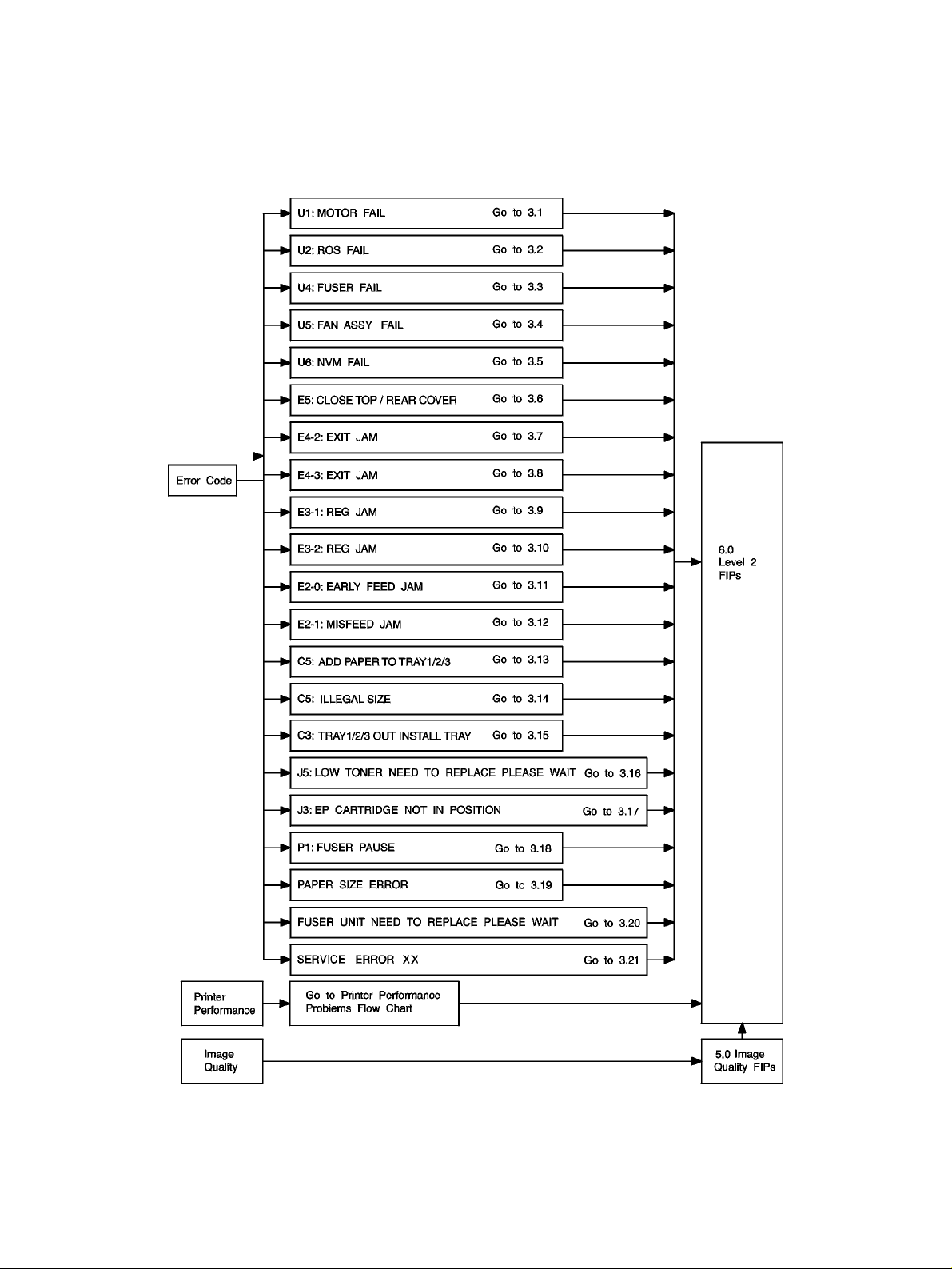
If you used the Service Flowchart, it should have directed you to this section. Now, follow the FIP Flowchart to analyze your printer problem.
How to Use the FIP Flowchart
1. If you have an error code displayed on the screen of the Diagnostic Tool; go to the ERROR CODE
box.
2. If you have a printer operation problem; go to the PRINTER PERFORMANCE box.
3. If you have a print image problem; go to the IMAGE QUALITY box.
4. Follow the arrow leading from your problem box to the individual FIP (Fault Isolation Procedure) that
corresponds to your error code, printer operation problem, or print image problem.
5. Follow the instructions presented in the FIP.
How to Follow a FIP
1. Each numbered step in a FIP instructs you to perform a certain action or procedure.
2. The instruction is followed by a question.
3. If your response to the question is Yes, then follow the instructions for a Yes reply.
4. If your response to the question is No, then follow the instructions for a No reply.
5. FIPs often ask you to take voltage readings at certain test points within the printer.
Appendices D and E contain information on signal names and test point locations.
6. FIPs often ask you to replace a printer component.
Section 9 Removal/Replacement provides you detailed procedures for removing and replacing all
major parts of the Asama printer.
2-2 HAKUBA 26PPM Laser Printer - Base Engine Technical Manual
Version1.0
Page 19

Fault Isolation Procedures
General Notes on Using FIPs
1. FIPs assume there is no malfunction in printer controller. If you are unable to fix a problem using the
FIPS, we recommend that you replace the printer controller.
2. FIPs use new and "known good" components as troubleshooting tools. We recommend you carry a
spare CRU, PWBA HKB MCU, and PWB ESS.
3. Unless indicated otherwise, the instruction "switch ON main power" means for you to switch ON printer
power, and let the printer proceed through power-on diagnostics and warm-up until it is on-line and
ready to print.
4. Conventions used to represent connectors:
P/J XX means a Plug and its corresponding Jack, are connected.
PXX means a Plug is disconnected. (Unless this plug is soldered to a PWB).
JXX means a Jack is disconnected. (Unless this jack is soldered to a PWB).
5. When you are instructed to take a voltage reading between "P/J A–B and P/J X–Y", place the red
probe (+) of your meter on pin B of P/J A, and place the black probe (–) of your meter on pin Y of P/J X.
6. When you are instructed to take voltage readings between "P/J X and P/J Y" (without specified pin
numbers), check all voltage carrying pins. Refer to the Wiring/Connection Diagrams for signals and pin
numbers.
7. When you are instructed to take a voltage reading, the black probe (–) is generally connected to a pin
that is either RTN (Return) or SG (Signal Ground). You can substitute any RTN pin or test point in the
printer, and you can use FG (Frame Ground) in place of any SG pin or test point.
8. Unless a FIP instructs you otherwise; before measuring voltages make sure the printer is switched
ON, the CRU and Cassette Assy are installed, and the Cover Assy Front and Cover Assy Rear are
closed (Interlock Switch is actuated).
9. All voltage values given in the FIPs are approximate values. Actual measured voltages may vary
somewhat from the given values.
10. FIPs may instruct you to remove or replace a component. Refer to Section 10 Removal and Replacement, for information on how to remove and reinstall a component.
11. When a FIP instructs you to replace a component, and that component is part of a larger assembly,
you should replace the entire assembly.
HAKUBA 26PPM Laser Printer - Base Engine Technical Manual 2-3
Version 1.0
Page 20
Fault Isolation Procedures
FIP Flowchart
2-4 HAKUBA 26PPM Laser Printer - Base Engine Technical Manual
Version1.0
Page 21

Primary FIPs:Error Codes
Section 3 Primary FIPs: Error Codes Contents
3.
Primary FIPs: Error Codes
3.1 U1:MOTOR FAIL . . . . . . . . . . . . . . . . . . . . . . . . . . . . . . . . . . . . . . . . . . . . . . . . . . . . . . . . . . . . . 3-8
3.2 U2:ROS FAIL . . . . . . . . . . . . . . . . . . . . . . . . . . . . . . . . . . . . . . . . . . . . . . . . . . . . . . . . . . . . . . . . 3-9
3.3 U4:FUSER FAIL . . . . . . . . . . . . . . . . . . . . . . . . . . . . . . . . . . . . . . . . . . . . . . . . . . . . . . . . . . . . . 3-10
3.4 U5:FAN ASSY FAIL . . . . . . . . . . . . . . . . . . . . . . . . . . . . . . . . . . . . . . . . . . . . . . . . . . . . . . . . . . 3-12
3.5 U6:NVM FAIL . . . . . . . . . . . . . . . . . . . . . . . . . . . . . . . . . . . . . . . . . . . . . . . . . . . . . . . . . . . . . . . 3-13
3.6 E5:CLOSE TOP/REAR COVER . . . . . . . . . . . . . . . . . . . . . . . . . . . . . . . . . . . . . . . . . . . . . . . . . 3-14
3.7 E4-2:EXIT JAM. . . . . . . . . . . . . . . . . . . . . . . . . . . . . . . . . . . . . . . . . . . . . . . . . . . . . . . . . . . . . . 3-15
3.8 E4-3:EXIT JAM. . . . . . . . . . . . . . . . . . . . . . . . . . . . . . . . . . . . . . . . . . . . . . . . . . . . . . . . . . . . . . 3-18
3.9 E3-1:REG JAM . . . . . . . . . . . . . . . . . . . . . . . . . . . . . . . . . . . . . . . . . . . . . . . . . . . . . . . . . . . . . . 3-20
3.10 E3-2:REG JAM . . . . . . . . . . . . . . . . . . . . . . . . . . . . . . . . . . . . . . . . . . . . . . . . . . . . . . . . . . . . . 3-23
3.11 E2-0:EARLY FEED JAM. . . . . . . . . . . . . . . . . . . . . . . . . . . . . . . . . . . . . . . . . . . . . . . . . . . . . . 3-25
3.12 E2-1:MISFEED JAM . . . . . . . . . . . . . . . . . . . . . . . . . . . . . . . . . . . . . . . . . . . . . . . . . . . . . . . . . 3-27
3.13 C5:ADD PAPER TO TRAY 1/2/3 . . . . . . . . . . . . . . . . . . . . . . . . . . . . . . . . . . . . . . . . . . . . . . . 3-30
3.14 C5:ILLEGAL SIZE . . . . . . . . . . . . . . . . . . . . . . . . . . . . . . . . . . . . . . . . . . . . . . . . . . . . . . . . . . 3-31
3.15 C3:TRAY 1/2/3 OUT INSTALL TRAY . . . . . . . . . . . . . . . . . . . . . . . . . . . . . . . . . . . . . . . . . . . . 3-32
3.16 J5:LOW TONER NEED TO REPLACE PLEASE WAIT . . . . . . . . . . . . . . . . . . . . . . . . . . . . . . 3-33
3.17 J3:EP CARTRIDGE NOT IN POSITION. . . . . . . . . . . . . . . . . . . . . . . . . . . . . . . . . . . . . . . . . . 3-34
3.18 P1:FUSER PAUSE . . . . . . . . . . . . . . . . . . . . . . . . . . . . . . . . . . . . . . . . . . . . . . . . . . . . . . . . . . 3-35
3.19 PAPER SIZE ERROR. . . . . . . . . . . . . . . . . . . . . . . . . . . . . . . . . . . . . . . . . . . . . . . . . . . . . . . . 3-36
3.20 FUSER UNIT NEED TO REPLACE PLEASE WAIT . . . . . . . . . . . . . . . . . . . . . . . . . . . . . . . . 3-37
3.21 SERVICE ERRORS . . . . . . . . . . . . . . . . . . . . . . . . . . . . . . . . . . . . . . . . . . . . . . . . . . . . . . . . . 3-38
. . . . . . . . . . . . . . . . . . . . . . . . . . . . . . . . . . . . . . . . . . . . 3-3
HAKUBA 26PPM Laser Printer - Base Engine Technical Manual 3-1
Version 1.0
Page 22

Primary FIPs:Error Codes
3. Level 1 FIPs: Error Codes
The FIP Flowchart should have directed you to this section.
Before entering the Error Code FIPs, make sure:
1. Is the printer plugged into a recommended AC wall outlet?
2. Is the AC power provided at the wall outlet within recommended specifications?
3. Is the AC power cord connected to the printer.
4. Is the AC power cord in good condition; not frayed or broken?
5. Is the printer properly grounded through the AC wall outlet?
6. Is the printer located in an area where the temperature and humidity are moderate and stable?
7. Is the printer located in an area that is free of dust?
8. Is the printer located in an area away from water outlets, steamers, electric heaters, volatile gases, or
open flames?
9. Is the printer shielded from the direct rays of the sun?
10. Does the printer have recommended space around all sides for proper ventilation?
11. Is the printer sitting on a level and stable surface?
12. Is recommended paper stock being used in the printer?
13. Does the customer use the printer as instructed in the HAKUBA User Manual?
14. Are consumables, such as the CRU, replaced at recommended intervals?
3-2 HAKUBA 26PPM Laser Printer - Base Engine Technical Manual
Version 1.0
Page 23

Code
--
Message
Cause
Primary FIPs:Error Codes
HAKUBA Error Codes
Results
-------------
How to Clear the Code
(If you cannot clear the code, go to
the appropriate error code FIP, or to
the option service manual)
U1
--
U1:MOTOR
FAIL
U2
--
U2:ROS FAIL
U4
--
U4:FUSER FAIL
There is a problem with the Motor Assy Main.
1. The rotation speed of the Motor Assy Main is
less than specified rpm and the state of a printer
does not turn READY, after the Motor Assy
Main started rotating 1.3 seconds passed.
2. The fail is detected during the Fan on operation.
There is a problem with the ROS Assy.
1. /BD signal intervals are longer than specified
value after ROS Motor start rotating.
2. After the interval of transmitting /BD signal
reaches the specified value, the interval is
longer than the specified value.
3. When the laser power does not reach the specified value.
There is a problem with the Fuser Assy.
1. Fuser Assy temperature is does not reach the
temperature even after 110 seconds passed.
2. Fuser Assy temperature gets lower than [Set
Temp. 125
°C
], in printing.
3. Fuser Assy temperature gets higher than [Set
Temp. 220
°C
].
Motor Assy Main, Laser Scanner,
and Fuser Assy controls stop at end
of print cycle.
-------------
Switch OFF Main Power.
Switch ON Main Power.
Motor Assy Main, Laser Scanner,
and Fuser Assy controls stop at end
of print cycle.
-------------
Switch OFF Main Power.
Switch ON Main Power.
Motor Assy Main, Laser Scanner,
and Fuser Assy controls stop at end
of print cycle.
-------------
Switch OFF Main Power.
Switch ON Main Power.
4. The thermistor disconnection is detected.
5. The heat lamp continuously turns on for 10 seconds during the Standby Mode.
U5
--
U5:Fan Assy
FAIL
There is a problem with the Fan Assy.
1. The Fan Motor stops rotating after the printer
power is turned on.
Motor Assy Main, Laser Scanner,
and Fuser Assy controls stop at end
of print cycle.
-------------
Switch OFF Main Power.
Switch ON Main Power.
U6
--
U6:NVM FAIL
There is a problem with NVRAM.
1. An NVRAM read error occurred immediately
when you switched ON main power.
2. A write error occurred when you tried to write to
NVRAM.
Motor Assy Main, Laser Scanner,
and Fuser Assy controls stop at end
of print cycle.
-------------
Switch OFF Main Power.
Switch ON Main Power.
3. The overflow of the Task Table.
HAKUBA 26PPM Laser Printer - Base Engine Technical Manual 3-3
Version 1.0
Page 24

Primary FIPs:Error Codes
HAKUBA Error Codes continued
Code
--
Message
Cause
Results
-------------
How to Clear the Code
(If you cannot clear the code, go to the
appropriate error code FIP, or to the
option service manual)
E5
--
CLOSE TOP /
REAR
COVER
E5
--
FACE UP TRY
OPEN
E4
--
E4-2:EXIT
JAM
E4
--
E4-3:EXIT
JAM
The Cover Assy Front and/or the Cover Rear are/
is open.
Motor Assy Main, Laser Scanner, and
Fuser Assy controls stop immediately.
-------------
Close the open cover.
The Cover Assy Rear Face Up is open. Motor Assy Main, Laser Scanner, and
Fuser Assy controls stop immediately.
-------------
Close the open cover.
There is a paper jam for the standard cut paper at
the Sensor Exit.
1. The Sensor Photo:Exit does not turn OFF
within the specified time after the Sensor Photo:
Exit turning ON.
2. The Sensor Photo:Exit turns ON immediately
Motor Assy Main, Laser Scanner, and
Fuser Assy controls stop immediately.
-------------
Open the Cover Assy Front or Rear.
Remove the jammed paper.
Close the Cover Assy Front or Rear.
after the power is turned on or when the Cover
Assy Front is close.
There is a paper jam at the Sensor Exit.
The paper of Universal or Custom does not actu-
ate the Sensor Photo:Exit within the specified time
from the Sensor Photo Regi OFF timing.
Motor Assy Main, Laser Scanner, and
Fuser Assy controls stop immediately.
-------------
Open the Cover Assy Front or Rear.
Remove the jammed paper.
Close the Cover Assy Front or Rear.
E3
--
E3-1:REG
JAM
There is a paper jam between the Sensor
Photo:Regi and the Sensor Exit in the Fuser Assy.
The paper does not actuate the Sensor Exit of the
Fuser Assy within the specified time after the Sensor Photo:Regi activated.
Motor Assy Main, Laser Scanner, and
Fuser Assy controls stop immediately.
-------------
Open the Cover Assy Front.
Remove the jammed paper.
Close the Cover Assy Front.
E3
--
E3-2:REG
JAM
There is a paper jam at the Regi position.
The Sensor Photo:Regi turns ON immediately
after the power is turned ON or when the Cover
Assy Front is close.
Motor Assy Main, Laser Scanner, and
Fuser Assy controls stop immediately.
-------------
Open the Cover Assy Front.
Remove the jammed paper.
Close the Cover Assy Front.
3-4 HAKUBA 26PPM Laser Printer - Base Engine Technical Manual
Version 1.0
Page 25

Code
--
Message
Cause
Primary FIPs:Error Codes
HAKUBA Error Codes continued
Results
-------------
How to Clear the Code
(If you cannot clear the code, go to the
appropriate error code FIP, or to the
option service manual)
E2
--
E2-0:EARLY-
FEED JAM
E2
--
E2-1:MIS-
FEED JAM
C5
--
C5:ADD
PAP ER T O
TRAY1/2/3
C5
--
C5:ILLEGAL
SIZE
There is a paper jam at the Sensor Photo:Regi.
The paper actuates the Sensor Photo:Regi too
early.
There is a paper jam at the Sensor Photo:Regi.
The paper does not reach the Sensor Photo:Regi
within the specified time.
Tray 1/2/3 is out of paper.
The Sensor Photo:No Pap1/2/3 on the PWBA
Feeder (PL3.1.36) is actuated.
The paper fed from the Tray 1/2/3 is different from
the NVM set size.
Motor Assy Main, Laser Scanner, and
Fuser Assy controls stop immediately.
-------------
Open the Cover Assy Front.
Remove the jammed paper.
Close the Cover Assy Front.
Motor Assy Main, Laser Scanner, and
Fuser Assy controls stop immediately.
-------------
Open the Cover Assy Front.
Remove the jammed paper.
Close the Cover Assy Front.
The printer completes only the current
print cycle.
-------------
ADD the paper to the Tray 1/2/3.
The printer completes only the current
print cycle.
-------------
Replace the stacked paper and reload
the correct size paper.
C3
--
C3:TRAY1
OUT INSTALL
TRAY
Tray 1 is not installed or installed not in the position.
Motor Assy Main, Laser Scanner, and
Fuser Assy controls stop immediately.
-------------
Reinstall Tray 1 completely.
HAKUBA 26PPM Laser Printer - Base Engine Technical Manual 3-5
Version 1.0
Page 26

Primary FIPs:Error Codes
HAKUBA Error Codes continued
Code
--
Message
Cause
Results
-------------
How to Clear the Code
(If you cannot clear the code, go to the
appropriate error code FIP, or to the
option service manual)
J5
--
J5:LOW
TONER NEED
TO REPLACE
PLEASE
WAIT
J5
--
J5:LOW
TONER NEED
TO REPLACE
READY TO
PRINT
J3
--
EP
CARTRIDGE
NOT IN POSI-
TION
P1
--
FUSER
PAUSE
The CRU is nearing end of life and needs to be
replaced soon.
Displays warning message.
-------------
Replace the CRU.
The CRU is nearing end of life and needs to be
replaced soon.
Displays warning message.
-------------
Replace the CRU.
The CRU is not installed or installed not in the
position.
Motor Assy Main, Laser Scanner, and
Fuser Assy controls stop immediately.
-------------
Reinstall the CRU, or install a new
CRU.
The printer received a SET PAUSE command. The ROS Motor and the Fuser Assy
controls stop after printing is completed.
-------------
Turn the Main Power OFF and ON.
--
PAPER SIZE
ERROR
The size of the paper loaded in the cassette is different than paper size that is stored in NVRAM.
In Duplex mode: The size of the paper loaded in
the cassette is not supported in Duplex Mode.
The printer completes the current print
cycle.
-------------
Rewrite the NVRAM using ADJUSTMENT MODE MENU.
3-6 HAKUBA 26PPM Laser Printer - Base Engine Technical Manual
Version 1.0
Page 27

Code
--
Message
Cause
Primary FIPs:Error Codes
HAKUBA Error Codes continued
Results
-------------
How to Clear the Code
(If you cannot clear the code, go to the
appropriate error code FIP, or to the
option service manual)
--
FUSER UNIT
NEED TO
REPLACE
PLEASE
WAIT
--
FUSER UNIT
NEED TO
REPLACE
READY TO
PRINT
The Fuser Assy is nearing end of life and better to
be replaced soon.
The Fuser Assy is nearing end of life and better to
be replaced soon.
Displays warning message.
-------------
Replace the Fuser Assy.
Displays warning message.
-------------
Replace the Fuser Assy.
HAKUBA 26PPM Laser Printer - Base Engine Technical Manual 3-7
Version 1.0
Page 28

Primary FIPs:Error Codes
3.1 U1:MOTOR FAIL
There is a problem with the Motor Assy Main.
Step Actions and Questions Yes No
1
2
3
INITIAL ANALYSIS
Inspect the following components.
• Motor Assy Main (PL8.1.14)
• PWBA HKB26 MCU (PL10.1.13)
• Gear Assy Drive (PL8.1.13)
• PWBA HKB PS (PL10.1.17)
Are they compatible with your printer version, correctly
installed, not damaged, deformed, or contaminated?
MOTOR ASSY MAIN ANALYSIS
Use MAIN MOTOR TEST to check the Motor Assy Main
(PL8.1.14).
Does the Motor Assy Main run?
MOTOR ASSY MAIN (PL8.1.14) ANALYSIS
1. Remove the Motor Assy Main from the Gear Assy Drive
(PL8.1.13). Do not unplug the Motor Assy Main from the
PWBA HKB26 MCU (PL10.1.13).
2. Use MAIN MOTOR TEST to check the Motor Assy Main.
Does the Motor Assy Main run?
Go to step 2. Replace the
problem components.
Replace the
PWBA HKB26
MCU
(RRP10.1.7).
Replace the
Gear Assy
Drive
(RRP8.1.3).
Go to step 3.
Go to step 4.
4
5
6
3-8 HAKUBA 26PPM Laser Printer - Base Engine Technical Manual
MOTOR ASSY MAIN (PL8.1.14) ANALYSIS
Check the voltage between P/J291-9 <=> P/J291-6, P/J291-8
<=> P/J291-5 and P/J291-7 <=> P/J291-4.
Is there +24VDC between P/J291-9 <=> P/J291-6, P/J291-8
<=> P/J291-5 and P/J291-7 <=> P/J291-4 on the Motor Assy
Main?
PWBA HKB26 MCU (PL10.1.13) ANALYSIS
Check the voltage between P/J29-1 <=> P/J29-4, P/J29-2 <=>
P/J29-5 and P/J29-3 <=> P/J29-6.
Is there +24VDC between P/J29-1 <=> P/J29-4, P/J29-2 <=>
P/J29-5 and P/J29-3 <=> P/J29-6 on the PWBA HKB26
MCU?
PWBA HKB PS (PL10.1.17) ANALYSIS
Check the voltage between P/J281-1 <=> P/J281-4, P/J281-2
<=> P/J281-5 and P/J281-3 <=> P/J281-6 on the PWBA LVPS
Is there +24VDC between the each P/J281-1 <=> P/J281-4,
P/J281-2 <=> P/J281-5 and P/J281-3 <=> P/J281-6 on the
PWBA HKB26 MCU?
Replace the
Motor Assy
Main
(RRP8.1.7).
Replace the
PWBA HKB26
MCU
(RRP10.1.7).
Replace the
PWBA HKB26
MCU
(RRP10.1.7).
Go to step 5.
Go to step 6.
Replace the
PWBA HKB
PS
(RRP10.1.7).
Version 1.0
Page 29

Primary FIPs:Error Codes
3.2 U2:ROS FAIL
There is a problem with the ROS Assy.
Step Actions and Questions Yes No
1
2
3
INITIAL ANALYSIS
Inspect the following components.
• ROS Assy (PL8.1.9)
• PWBA HKB26 MCU (PL10.1.13)
• PWBA HKB PS (PL10.1.17)
• CRU (PL8.1.1)
• Harness Assy ROS (J21-J211, J212, J213) (PL8.1.7)
• Harness Assy VDO (J22-J233) (PL8.1.8)
Are they compatible with your printer version, correctly
installed, not damaged, deformed, or contaminated?
NVRAM ANALYSIS
Check the parameter using ADJUSTMENT MODE MENU.
Is the parameters set correctly?
ROS MOTOR ANALYSIS
1. Check the ROS Motor using ROS MOTOR TEST.
2. If you cannot hear the ROS Motor running, unplug P/J29
(Motor Assy Main).
Can you hear the ROS Motor running before the U2 code
appears?
Go to step 2. Replace the
problem components.
Go to step 3. Set correct
paramete.r
Go to step 4. Go to 6.3
ROS Assy
Failure.
4
HAKUBA 26PPM Laser Printer - Base Engine Technical Manual 3-9
Version 1.0
LD DIODE ANALYSIS
1. Disconnect P/J22 and P/J21 on the PWBA HKB26 MCU
(PL8.1.13).
2. Close the Cover Assy Front (PL1.1.9).
3. Switch ON Main Power.
4. Check the voltage between P21-5 and P21-6.
Is there +5 VDC between P21-5 and P21-6?
Go to 6.3
ROS Assy
Failure.
Go to 6.1
PWBA HKB
PS Failure
(+3.3 VDC).
Page 30

Primary FIPs:Error Codes
3.3 U4:FUSER FAIL
There is a problem with the Fuser Assy.
Step Actions and Questions Yes No
1
2
INITIAL ANALYSIS
Inspect the following components.
• Fuser Assy (PL6.1.7)
• Harness Assy Fuser-M (J271, J11, J27, J262) (PL6.1.12)
• PWBA HKB26 MCU (PL10.1.13)
• PWBA HKB PS (PL10.1.17)
• Switch Assy I/L Front (PL10.1.12)
• Switch Assy I/L Rear (PL10.1.7)
• Sensor Photo Exit in the Fuser Assy (PL6.1.7)
Are they compatible with your printer version, correctly
installed, not damaged, deformed, or contaminated?
SWITCH ASSY I/L FRONT (PL10.1.12) ANALYSIS
Check the Switch Assy I/L Front function using SENSOR/
SWITCH CHECH.
Does the Switch Assy I/L Front function correctly and
increment the Sensor Check number each time you actuate it?
Go to step 2. Replace the
problem components.
Go to step 3. Replace the
Switch Assy I/
L Front
(RRP10.1.12)
3
4
5
6
3-10 HAKUBA 26PPM Laser Printer - Base Engine Technical Manual
SWITCH ASSY I/L REAR (PL10.1.7) ANALYSIS
Check the Switch Assy I/L Rear function using SENSOR/
SWITCH CHECH.
Does the Switch Assy I/L Rear function correctly and
increment the Sensor Check number each time you actuate it?
HARNESS ASSY FUSER-M (J271, J11, J27, J262)
(PL6.1.12) ANALYSIS
Is there continuity between J271 and J11?
HEATER ASSY ANALYSIS
Does U4 appear after POWER–ON?
(Answer YES if there is a momentary Fuser Assy Warm-Up
Sequence)
HEAT ROD ANALYSIS
Let the Heat Rod cool down.
Does the Heat Rod glow when power is switched ON?
Go to step 4. Replace the
Switch Assy I/
L Rear
(RRP10.1.5).
Go to step 5. Replace the
Harness Assy
Fuser-M
(J271, J11,
J27, J262)
(RRP6.1.4).
Go to 6.5
Temperature
Sensor Failure.
Go to step 6. Go to 6.4
Go to step 6.
Heat Rod
Failure.
Version 1.0
Page 31

Primary FIPs:Error Codes
3.3 U4:FUSER FAIL continued
Step Actions and Questions Yes No
7
8
9
10
Does the Heat Rod switch ON and OFF after Power–On
Sequence?
HEAT ROD ANALYSIS
Is there proper VAC between P/J11-1 and P/J11-2?
PWBA HKB PS (PL10.1.17) ANALYSIS
Perform this check within 65 seconds after switching power
ON. After specified seconds, PWBA HKB PS shuts down due
to a no–load condition.
Is there +3.3VDC between P/J281-10 and P/J28-8 on the
PWBA HKB PS?
HEAT ROD ACTUATOR SIGNAL ANALYSIS
Disconnect P/J28 on the PWBA HKB26 MCU (PL10.1.13).
Is there 0VDC between P/J 28-12 and P/J 28-8 on the
PWBA HKB26 MCU during Power–ON sequence, and does
the voltage rise to +3.3VDC when the sequence finishes?
Go to step 8. Go to step 9.
Go to 6.5
Temperature
Sensor Failure.
Go to step 10. Go to 6.1
Go to 6.1
PWBA HKB
PS Failure
(+3.3 VDC).
Replace the
PWBA HKB
PS
(RRP10.1.7).
LVPS Failure
(+3.3VDC).
Replace the
PWBA HKB26
MCU
(RRP10.1.7).
HAKUBA 26PPM Laser Printer - Base Engine Technical Manual 3-11
Version 1.0
Page 32

Primary FIPs:Error Codes
3.4 U5:FAN ASSY FAIL
There is a problem with the Fan Assy.
Step Actions and Questions Yes No
1
2
3
INITIAL ANALYSIS
Inspect the following components.
• Fan Assy (PL9.1.7)
• PWBA HKB26 MCU (PL10.1.13)
• PWB ESS (PL10.1.2)
Are they compatible with your printer version, correctly
installed, not damaged, deformed, or contaminated?
FAN ASSY (PL9.1.7) ANALYSIS
Can you hear or see the Fan Assy spinning when you
power-on the printer?
FAN ASSY SIGNAL ANALYSIS
Check the voltage between P/J28-13 and P/J28-8 on the
PWBA HKB26 MCU (PL10.1.13) while the U5 code is displayed.
Is there +3.3VDC between P/J28-13 and P/J28-8?
Go to step 2. Replace the
problem components.
Go to step 3. Go to 6.16
Fan Assy Failure.
Replace the
Fan Assy
(RRP9.1.2).
Replace the
PWBA HKB26
MCU
(RRP10.1.7).
3-12 HAKUBA 26PPM Laser Printer - Base Engine Technical Manual
Version 1.0
Page 33

Primary FIPs:Error Codes
3.5 U6:NVM FAIL
There is a problem with NVRAM.
Step Actions and Questions Yes No
1
2
3
4
5
INITIAL ANALYSIS
Inspect the following component.
• PWBA HKB26 MCU (PL10.1.13)
Is it compatible with your printer version, correctly
installed, not damaged, deformed, or contaminated?
Does U6 appear after you switch ON Main Power? Go to step 5. Problem cor-
Switch Main Power OFF and ON several times.
Does U6 still appear when you switch ON Main Power
again?
PWBA HKB26 MCU (PL10.1.13) ANALYSIS
Enter DIAGNOSTIC MODE MENU.
Can you enter DIAGNOSTIC MODE MENU?
NVRAM ANALYSIS
Enter ADJUSTMENT MODE MENU and check the parameters
for each value of NVRAM Code.
Are all parameters set correctly?
Go to step 2. Replace the
problem component.
rected.
Go to step 4. Problem
solved.
Go to step 5. Replace the
PWBA HKB26
MCU
(RRP10.1.7).
(If U6 continues, go to
6.20 Electrical Noise).
Replace the
PWBA HKB26
MCU
(RRP10.1.7).
Go to step 6.
6
HAKUBA 26PPM Laser Printer - Base Engine Technical Manual 3-13
Version 1.0
PWBA HKB26 MCU (PL10.1.13) ANALYSIS
1. Enter correct parameters.
2. Switch OFF Main Power.
3. Switch ON Main Power.
Does U6 still appear?
Replace the
PWBA HKB26
MCU
(RRP10.1.7).
Problem
solved.
Return to Service Flowchart.
Page 34

Primary FIPs:Error Codes
3.6 E5:CLOSE TOP / REAR COVER
An Interlock Switch is not actuated.
Step Actions and Questions Yes No
1
2
3
INITIAL ANALYSIS
Inspect the following components.
• PWBA HKB26 MCU (PLPL10.1.13)
• PWBA LVPS (PL10.1.17)
• Switch Assy I/L Rear (PL10.1.7)
• Cover Rear (PL1.2.5)
Are they compatible with your printer version, correctly
installed, not damaged, deformed, or contaminated?
SWITCH ASSY I/L REAR (PL10.1.7) ANALYSIS
1. Check the Switch Assy I/L Rear using SENSOR/SWITCH
CHECK.
2. Open and close the Cover Rear (PL1.2.5).
Does the Switch Assy I/L Rear function correctly and
increment the Sensor Check number on the screen each
time you actuate it?
SWITCH ASSY I/L REAR (PL10.1.7) ANALYSIS
Check the voltage between P/J30-2 and P/J30-1.
Is there +24VDC between P/J30-2 and P/J30-1 with the
Cover Rear (PL1.2.5) closed?
Go to step 2. Replace the
problem components.
Go to step 3. Replace the
Switch Assy I/
L Rear
(RRP10.1.5).
Replace the
Cover Rear
(PL1.2.5).
Replace the
PWBA HKB26
MCU
(RRP10.1.7).
3-14 HAKUBA 26PPM Laser Printer - Base Engine Technical Manual
Version 1.0
Page 35

Primary FIPs:Error Codes
3.7 E4-2:EXIT JAM
There is a paper jam in the exit area of the paper path.
Step Actions and Questions Yes No
1
INITIAL ANALYSIS
Inspect the following components.
• PWBA HKB26 MCU (PL10.1.13)
• Cassette Assy (PL2.1.1)
• Switch Size on the PWBA Feeder (PL3.1.36)
• Fuser Assy (PL6.1.7)
• PWBA LVPS (PL10.1.17)
• Motor Assy Exit (PL7.1.21)
• Actuator Full Stack (PL7.1.2)
• Sensor Photo:Exit (PL7.1.17)
• Feeder Assy (PL3.1.19)
• Option Feeder Assy (PL11.1.1)
• Sensor Photo: Face Control Paper (PL3.1.13)
• Motor Assy (PL2.2.22)
Are they compatible with your printer version, correctly
installed, not damaged, deformed, or contaminated?
Go to step 2. Replace the
problem components.
2
3
4
5
HAKUBA 26PPM Laser Printer - Base Engine Technical Manual 3-15
Version 1.0
Does the error code appear immediately after you switch
ON Main Power?
Is there paper jammed at the Sensor Exit in the Fuser
Assy (PL6.1.7)?
DECURL ROLL of the FUSER ASSY (PL6.1.7) ANALYSIS
Check the rotation of Decurl Roll using MAIN MOTOR TEST.
Inspect the Decurl Roll operation.
Does the Decurl Roll rotate smoothly?
DECURL ROLL of the FUSER ASSY (PL6.1.7) ANALYSIS
Open the Cover Rear (PL1.2.5) and cheat the interlock switch.
Generate a test print to check the Decurl Roll.
Does the paper pass through the Decurl Roll without problems?
Go to step 3. Go to step 4.
Remove the
paper.
Go to step 5. Replace the
Go to step 6. Replace the
Go to step 7.
Fuser Assy
(RRP6.1.3).
Fuser Assy
(RRP6.1.3).
Page 36

Primary FIPs:Error Codes
3.7 E4-2:EXIT JAM continued
Step Actions and Questions Yes No
6
7
8
SENSOR EXIT of the FUSER ASSY (PL6.1.7) ANALYSIS
1. Check the Sensor Exit of the Fuser Assy using SENSOR/
SWITCH CHECK.
2. Manually feed a sheet of paper into the Fuser Assy, then
remove the sheet of paper.
Does the Exit Actuator move freely and without binding
and does the Sensor Exit function correctly and increment
the Sensor Check number on the screen each time you
actuate the
ACTUATOR CST (PL21.1.19) ANALYSIS
Remove the Cassette Assy (PL2.1.1). Inspect the combination
of the Actuator CST.
Does the combination of the Actuator CST show the correct combination for the paper size present in the cassette?
ROLL ASSY MID 1, MID 2 and MID3 (PL7.1.7 and PL7.1.11)
ANALYSIS
Check the operation of the Roll Assies MID.
Does the Roll Assies MID function normally?
ensor?
S
Go to step 7. Replace the
Fuser Assy
(RRP6.1.3).
Go to 6.12
Paper Size
Sensor Failure.
Go to step 10. Go to step 9.
Replace the
Cassette
Assy.
9
3-16 HAKUBA 26PPM Laser Printer - Base Engine Technical Manual
MOTOR ASSY EXIT (PL7.1.21) ANALYSIS
Check the voltage between P/J32-1 and frame ground.
Is there +24VDC between P/J32-1 and frame ground?
Replace the
Motor Assy
Exit
(RRP7.1.7).
Replace the
PWBA HKB26
MCU
(RRP10.1.7).
Version 1.0
Page 37

Primary FIPs:Error Codes
3.7 E4-2:Exit JAM continued
Step Actions and Questions Yes No
10
11
ACTUATOR FULL STACK (PL7.1.2) ANALYSIS
Fill the Exit Tray with paper.
Does the paper lift the Actuator Full Stack, and does the
Actuator expose the photo-sensing point of the Sensor
Photo:Exit (PL7.1.16)?
SWITCH ASSY I/L REAR (PL10.1.7) ANALYSIS
Use SENSOR/ SWITCH CHECK to check the function of the
Switch Assy I/L Rear.
Open and close the Cover Rear (PL1.2.5).
Does the Switch Assy I/L Rear function correctly and
increment the Sensor Check number on the screen each
time you actuate it?
Go to step 11. Replace the
Actuator Full
Stack
(RRP7.1.2) or
replace the
Sensor
Photo:Exit
(RRP7.1.5).
Replace the
PWBA HKB26
MCU
(RRP10.1.7).
Replace the
Cover Rear
(PL1.2.5).
HAKUBA 26PPM Laser Printer - Base Engine Technical Manual 3-17
Version 1.0
Page 38

Primary FIPs:Error Codes
3.8 E4-3:Exit JAM
There is a paper jam between the sensor Photo Regi and the Sensor Photo Exit.
Step Actions and Questions Yes No
1
2
3
4
INITIAL ANALYSIS
Inspect the following components.
• PWBA HKB26 MCU (PL10.1.13)
• P/H Assy (PL5.1.4)
• Switch Size on the PWBA Feeder (PL3.1.36)
• Fuser Assy (PL6.1.7)
• PWBA LVPS (PL10.1.17)
• Motor Assy Exit (PL7.1.21)
• Actuator Full Stack (PL7.1.2)
• Sensor Photo:Exit (PL7.1.17)
Are they compatible with your printer version, correctly
installed, not damaged, deformed, or contaminated?
Does the error code appear immediately after you switch
ON Main Power?
Is there paper jammed at the Sensor Exit in the Fuser
Assy (PL6.1.7)?
DECURL ROLL of the FUSER ASSY (PL6.1.7) ANALYSIS
Check the rotation of Decurl Roll using MAIN MOTOR TEST.
Remove the CRU (PL8.1.1) and inspect the Decurl Roll operation.
Go to step 2. Replace the
problem components.
Go to step 3. Go to step 4.
Remove the
paper.
Go to step 5. Replace the
Go to step 7.
Fuser Assy
(RRP6.1.3).
Does the Decurl Roll rotate smoothly?
5
3-18 HAKUBA 26PPM Laser Printer - Base Engine Technical Manual
DECURL ROLL of the FUSER ASSY (PL6.1.7) ANALYSIS
Open the Cover Rear (PL1.2.5) and cheat the interlock switch.
Generate a test print to check the Decurl Roll.
Does the paper pass through the Decurl Roll without problems?
Go to step 6. Replace the
Fuser Assy
(RRP6.1.3).
Version 1.0
Page 39

Primary FIPs:Error Codes
3.8 E4-3:Exit JAM continued
Step Actions and Questions Yes No
6
7
8
9
SENSOR EXIT in the FUSER ASSY (PL6.1.7) ANALYSIS
1. Check the Sensor Exit in the Fuser Assy using SENSOR/
SWITCH CHECH.
2. Manually feed a sheet of paper into the Fuser Assy, then
remove the sheet of paper.
Does the Exit Actuator move freely and without binding
and does the Sensor Exit function correctly and increment
the Sensor Check number on the screen each time you
actuate the
ROLL ASSY MID 1, MID 2 and MID3 (PL7.1.7 and PL7.1.11)
ANALYSIS
Check the operation of the Roll Assis MID.
Does the Roll Assis MID function normally?
MOTOR ASSY EXIT (PL7.1.21) ANALYSIS
Check the voltage between P/J32-1 and frame ground.
Is there +24VDC between P/J32-1 and frame ground?
ACTUATOR FULL STACK (PL7.1.2) ANALYSIS
Fill the Exit Tray with paper.
Does the paper lift the Actuator Full Stack, and does the
Actuator expose the photo-sensing point of the Sensor
Photo:Exit (PL7.1.16)?
ensor?
S
Go to step 7. Replace the
Fuser Assy
(RRP6.1.3).
Go to step 9. Go to step 8.
Replace the
Motor Assy
Exit
(RRP7.1.7).
Go to step 10. Replace the
Replace the
PWBA HKB26
MCU
(RRP10.1.7).
Actuator Full
Stack
(RRP7.1.2) or
replace the
Sensor
Photo:Exit
(RRP7.1.5).
10
HAKUBA 26PPM Laser Printer - Base Engine Technical Manual 3-19
Version 1.0
SWITCH ASSY I/L REAR (PL10.1.7) ANALYSIS
1. Use SENSOR/ SWITCH CHECK to check the function of
the Switch Assy I/L Rear.
2. Open and close the Cover Rear (PL1.2.5).
Does the Switch Assy I/L Rear function correctly and
increment the Sensor Check number on the screen each
time you actuate it?
Replace the
PWBA HKB26
MCU
(RRP10.1.7).
Replace the
Cover Rear
(PL1.2.5).
Page 40

Primary FIPs:Error Codes
3.9 E3-1:REG JAM
There is a paper jam between the Sensor Photo Regi and the Sensor Exit of the Fuser Assy.
Step Actions and Questions Yes No
1
2
INITIAL ANALYSIS
Inspect the following components.
• Clutch Regi (PL 5.1.19)
• Sensor Photo:Regi (PL5.1.12)
• Actuator Regi (PL5.1.10)
• Roll Regi Metal (PL5.1.5)
• Roll Regi Rubber (PL5.1.7)
• BTR Assy (PL6.1.2)
• CRU (PL8.1.1)
• Harness Assy Regi (J43-J431, NJ432) (PL5.1.28)
• Harness Assy Conn (J23-J231) (PL10.1.10)
• PWBA Conn (PL10.1.11)
• PWBA HKB26 MCU (PL10.1.13)
• PWBA HKB PS (PL10.1.17)
• Gear Assy Drive (PL8.1.13)
Are they compatible with your printer version, correctly
installed, not damaged, deformed, or contaminated?
Is the paper that is loaded in the paper tray wrinkled or
damaged?
Go to step 2. Replace the
problem components.
Replace with
fresh, dry
paper.
Go to step 3.
3
4
5
3-20 HAKUBA 26PPM Laser Printer - Base Engine Technical Manual
Is there a sheet of paper at the Actuator Regi when the E3
code appears?
PAPER SIZE ANALYSIS
1. Check the size of paper currently loaded.
2. A paper jam can occur if the paper used is larger or smaller
than the maximum or minimum size specified for this printer.
Does the paper size meet specifications?
GEAR ASSY DRIVE (PL8.1.13) ANALYSIS
1. Use MAIN MOTOR TEST to check the Gear Assy Drive
function.
2. Open the Cover Assy Front (PL1.1.9).
3. Remove the CRU (PL8.1.1).
4. Actuate the Switch Assy I/L Front (PL10.1.12).
Do the transmission gears rotate correctly against those
of the Roll Assy Turn (PL3.1.1), the Feeder Assy
(PL3.1.19), Clutch Regi (PL5.1.19)?
Remove the
jammed
paper.
Go to step 5. Load paper
Go to step 7. Go to step 6.
Go to step 4.
that meets
specifications.
Version 1.0
Page 41

Primary FIPs:Error Codes
3.9 E3-1:REG JAM continued
Step Actions and Questions Yes No
6
7
8
9
CLUTCH REGI (PL5.1.19) ANALYSIS
Check the voltage between P/J43-1 and P/J43-2.
Is there +24VDC between P/J43-1 and P/J43-2?
ROLL REGI METAL (PL 5.1.5) and ROLL REGI RUBBER
(PL5.1.7) ANALYSIS
1. Open the Cover Assy Front (PL1.1.9).
2. Remove the CRU (PL8.1.1).
3. Actuate the Switch Assy I/L Front (PL10.1.12).
4. Check the rotation of the Roll Regi Metal and Roll Regi Rub-
ber using MAIN MOTOR TEST.
Does the Roll Regi Metal and Roll Regi Rubber rotate
properly?
SENSOR PHOTO: REGI (PL5.1.12) ANALYSIS
1. Use SENSOR/ SWITCH CHECK to check the Sensor
Photo:Regi.
2. Use a sheet of paper to actuate the sensor.
Does the Sensor Photo: Regi function correctly and increment the Sensor Check number on the screen each time
you actuate it?
HARNESS ASSY REGI (J43-J431, J432) (PL5.1.28) ANALYSIS
1. Disconnect the Harness Assy Regi (J43-J431, J432) from
the PWBA Conn (PL10.1.11).
Go to step 7. Go to 6.2
PWBA HKB
PS Failure
(+24VDC).
Go to step 8. Replace the
P/H Assy
(RRP5.1.1).
Go to step 11. Go to step 9.
Go to step 10. Replace the
Harness Assy
Regi (J43J431, J432).
2. Check the continuity between J43-3 <=> J432-3, J43-4 <=>
J432-2 and J43-5 <=> J432-1.
Is there the continuity between J43-3 <=> J423-3, J43-4
<=> J432-2 and J43-5 <=> J432-1?
10
HAKUBA 26PPM Laser Printer - Base Engine Technical Manual 3-21
Version 1.0
PWBA CONN (PL10.1.11) ANALYSIS
1. Disconnect the Harness Assy Conn (J23-J231) (PL10.1.10)
from the PWBA HKB26 MCU (PL10.1.13).
2. Check the continuity between P231-7 <=> P41-3, P231-6
<=> P41-5 and P231-10 <=> P43-4.
Is there the continuity between J231-7 <=> J41-3, J231-6
<=> J41-5 and J231-10 <=> J43-4?
Replace the
PWBA HKB26
MCU
(RRP10.1.7).
Replace the
PWBA Conn
(RRP10.1.5).
Page 42

Primary FIPs:Error Codes
3.9 E3-1:REG JAM continued
Step Actions and Questions Yes No
11
12
13
14
15
DRUM SHUTTER of the CRU (PL8.1.1) ANALYSIS
Does the Drum Shutter open when you install the CRU?
BTR ASSY (PL6.1.2) ANALYSIS
1. Remove the CRU, so you can inspect the BTR Assy.
2. Check the rotation of the BTR Assy.
Does the BTR Assy rotate smoothly?
BTR CHUTE ASSY (PL6.1.1) ANALYSIS
Inspect the BTR Chute Assy.
Is the BTR Chute Assy clean and free of contamination?
HEAT & PRESSURE ROLL of the FUSER ASSY (PL6.1.7)
ANALYSIS
Check the rotation of the Heat and Pressure Rolls using MAIN
MOTOR TEST.
Are the Heat and Pressure Rolls rotating normally?
DECURL ROLL of the FUSER ASSY (PL6.1.7) ANALYSIS
1. Open the Cover Rear (PL1.2.5) and cheat the Switch Assy I/
L Rear (PL10.1.7).
Go to step 12. Replace the
CRU
(PL8.1.1).
Go to step 13. Replace the
BTR Assy
(RRP6.1.1).
Clean or
replace the
BTR Assy
(RRP6.1.1) or
Chute Assy
Trans
(RRP6.1.2).
Go to step 15. Replace the
Go to step 16 Replace the
Go to step 14.
Fuser Assy
(RRP6.1.3).
Fuser Assy
(RRP6.1.3)
2. Execute a test print to check the Decurl Roll.
Does the paper pass through the Decurl Roll without problems?
16
17
3-22 HAKUBA 26PPM Laser Printer - Base Engine Technical Manual
ACTUATOR EXIT of the Fuser Assy (PL6.1.7) ANALYSIS
Does the Exit Actuator move smoothly when a sheet of
paper strikes it?
SENSOR EXIT of the Fuser Assy (PL6.1.7) ANALYSIS
Check the Sensor Exit function using SENSOR/SWITCH
CHECK.
Does the Sensor Exit function correctly and increment the
Sensor Check number on the screen each time you actuate it?
Go to step 17. Replace the
Fuser Assy
(RRP6.1.3).
Replace the
PWBA HKB26
MCU
(RRP10.1.7).
Replace the
Fuser Assy
(RRP6.1.3).
Version 1.0
Page 43

Primary FIPs:Error Codes
3.10 E3-2:REG JAM
There is a paper jam at the Regi position.
Step Actions and Questions Yes No
1
2
3
4
INITIAL ANALYSIS
Inspect the following components.
• Sensor Photo:Regi (PL5.1.12)
• Actuator Regi (PL5.1.10)
• PWBA Conn (PL10.1.11)
• PWBA HKB26 MCU (PL10.1.13)
• PWBA HKB PS (PL10.1.17)
• Gear Assy Drive (PL8.1.13)
Are they compatible with your printer version, correctly
installed, not damaged, deformed, or contaminated?
Is the paper that is loaded in the paper tray wrinkled or
damaged?
Is there a sheet of paper at the Actuator Regi when the E3
code appears?
SENSOR PHOTO REGI (PL5.1.12) ANALYSIS
1. Use SENSOR/ SWITCH CHECK to check the Sensor
Photo: Regi.
2. Use a sheet of paper to actuate the sensor.
Does the Sensor Regi function correctly and increment
the Sensor Check number on the screen each time you
actuate it?
Go to step 2. Replace the
problem components.
Replace with
fresh, dry
paper.
Remove the
jammed
paper.
Go to step 5. Replace the
Go to step 3.
Go to step 4.
Sensor Photo:
Regi
(RRP5.1.5).
5
HAKUBA 26PPM Laser Printer - Base Engine Technical Manual 3-23
Version 1.0
HARNESS ASSY REGI (J43-J431, J432) (PL5.1.28) ANALYSIS
1. Disconnect the Harness Assy Regi (J43-J431, J432) from
the PWBA Conn (PL10.1.11).
2. Check the continuity between J43-3 <=> J432-3, J43-4 <=>
J432-2 and J43-5 <=> J432-1.
Is there the continuity between J43-3 <=> J423-3, J43-4
<=> J432-2 and J43-5 <=> J432-1?
Go to step 6. Replace the
Harness Assy
Regi (J43J431, J432).
Page 44

Primary FIPs:Error Codes
3.10 E3-2:REG JAM continued
Step Actions and Questions Yes No
6
PWBA CONN (PL10.1.11) ANALYSIS
1. Disconnect the Harness Assy Conn (J23-J231) (PL10.1.10)
from the PWBA HKB26 MCU (PL10.1.13).
2. Check the continuity between P231-7 <=> P41-3, P231-6
<=> P41-5 and P231-10 <=> P43-4.
Is there the continuity between J231-7 <=> J41-3, J231-6
<=> J41-5 and J231-10 <=> J43-4?
Replace the
PWBA HKB26
MCU
(RRP10.1.7).
Replace the
PWBA Conn
(RRP10.1.5).
3-24 HAKUBA 26PPM Laser Printer - Base Engine Technical Manual
Version 1.0
Page 45

Primary FIPs:Error Codes
3.11 E2-0:EARLY FEED JAM
There is a paper jam at the Sensor Photo:Regi.
The paper arrives at the Sensor Photo:Regi too early.
Step Actions and Questions Yes No
1
Inspect the following components.
• Chute CST(PL5.1.27)
• Chute Bottom Lower (PL5.1.26)
• Sensor Photo:Regi (PL5.1.12)
• Actuator Regi (PL5.1.10)
• Spring Sensor Regi (PL5.1.11)
• Clutch Regi (PL5.1.19)
• Roll Regi Metal (PL5.1.5)
• Roll Regi Rubber (PL5.1.7)
• Roll Assy (PL2.2.8) of the Cassette Sub-Assy (PL2.2.1)
• Option Feeder Assy (PL11.1.1)
• Gear Assy Drive (PL8.1.13)
• PWBA Conn (PL10.1.11)
• PWBA HKB26 MCU (PL10.1.13)
• PWBA HKB PS (PL10.1.17)
• Harness Assy Regi (J43-J431, J423) (PL5.1.28)
• Harness Assy Conn (J23-J231) (PL10.1.10)
Are they compatible with your printer version, correctly
installed, not damaged, deformed, or contaminated?
Go to step 2. Replace the
problem component.
2
3
HAKUBA 26PPM Laser Printer - Base Engine Technical Manual 3-25
Version 1.0
Is a piece of paper or foreign object actuating the Sensor
Photo:Regi (PL5.1.12)?
ROLL ASSY (PL2.2.8) and the CLUTCH ASSY FRICTION
(PL2.2.7) of the CASSETTE SUB-ASSY (PL2.2.1) ANALYSIS
1. Remove the CRU (PL8.1.1).
2. Actuate the Switch Assy I/L Front (PL10.1.12).
3. Observe the paper feed from the Feeder Assy using MAIN
MOTOR TEST.
Is only one sheet of paper fed from the Feeder Assy?
Remove the
piece of paper
or foreign
object.
Go to step 4. Replace the
Go to step 3.
Roll Assy
(PL2.2.8) and
the Clutch
Assy Friction
(PL2.2.7).
Page 46

Primary FIPs:Error Codes
3.11 E2-0:EARLY FEED JAM continued
Step Actions and Questions Yes No
4
5
6
ACTUATOR CST (PL21.1.19) ANALYSIS
Remove the Cassette Assy (PL2.1.1). Inspect the combination
of the Actuator CST.
Does the combination of the Actuator CST show the correct combination for the paper size present in the cassette?
ACTUATOR REGI (PL5.1.10) ANALYSIS
Does the Actuator Regi expose the sensing point of the
Sensor Photo:Regi (PL5.1.12) when a sheet of paper
strikes the actuator, and does the Actuator Regi block the
sensing point of the Sensor Photo:Regi when there is no
paper striking the actuator?
SENSOR PHOTO:REGI (PL5.1.12) ANALYSIS
Use SENSOR/SWITCH CHECK to check the Sensor Photo
Regi.
Does the Sensor Photo:Regi function correctly and increment the Sensor Check number on the screen each time
you actuate it?
Go to step 5. Replace the
loaded paper
to the proper
one.
Go to step 6. Replace the
Actuator Regi
(RRP5.1.3).
Replace the
PWBA HKB26
MCU
(RRP10.1.7).
Go to 7.7
Sensor
Photo:Regi
Failure.
3-26 HAKUBA 26PPM Laser Printer - Base Engine Technical Manual
Version 1.0
Page 47

Primary FIPs:Error Codes
3.12 E2-1:MISFEED JAM
There is a paper jam at the Sensor Photo:Regi. The paper does not reach the Sensor Photo:Regi within the specified
time.
Step Actions and Questions Yes No
1
Inspect the following components.
• Cassette Assy (PL21.1.1)
• Feeder Assy (PL3.1.19)
• Clutch Assy Feed (PL3.1.37)
• Sensor Photo: Face Control Paper (PL3.1.13)
• Motor Assy (PL2.2.22)
• Clutch Assy Turn (PL3.1.2)
• Roll Assy Turn (PL3.1.1)
• Chute CST (PL5.1.27)
• Chute Bottom Lower (PL5.1.26)
• Sensor Photo:Regi (PL5.1.12)
• Actuator Regi (PL5.1.10)
• Spring Sensor Regi (PL5.1.11)
• Clutch Regi (PL5.1.19)
• Roll Regi Metal (PL5.1.5)
• Roll Regi Rubber (PL5.1.7)
• Roll Assy (PL2.2.8) of the Cassette Sub-Assy (PL2.2.1)
• Option Feeder Assy (PL11.1.1)
• Gear Assy Drive (PL8.1.13)
• PWBA Feeder (PL3.1.36 or PL11.2.36)
• PWBA Side 1 (PL 9.1.19)
• PWBA Conn (PL10.1.11)
• PWBA HKB26 MCU (PL10.1.13)
• PWBA HKB PS (PL10.1.17)
• Harness Assy Regi (J43-J431, J423) (PL5.1.28)
• Harness Assy Feeder (J33-J331) (PL9.1.13)
• Harness Assy Size M (J51-P511) (PL9.1.20)
• Harness Assy Conn (J23-J231) (PL10.1.10)
Go to step 2. Replace the
problem component.
2
HAKUBA 26PPM Laser Printer - Base Engine Technical Manual 3-27
Version 1.0
Is the paper that is loaded in the paper tray wrinkled or
damaged?
Replace with
fresh, dry
paper.
Go to step 3.
Page 48

Primary FIPs:Error Codes
3.12 E2-1:MISFEED JAM continued
Step Actions and Questions Yes No
3
4
5
6
Is there a sheet of paper before the Actuator Regi when
the E2-1 code appears?
PAPER SIZE ANALYSIS
1. Check the size of paper currently loaded.
2. A paper jam can occur if the paper used is larger or smaller
than the maximum or minimum size specified for this printer.
Does the paper size meet specifications?
GEAR ASSY DRIVE (PL8.1.13) ANALYSIS
1. Use MAIN MOTOR TEST to check the Gear Assy Drive
function.
2. Open the Cover Assy Front (PL1.1.9).
3. Remove the CRU (PL8.1.1).
4. Actuate the Switch Assy I/L Front (PL10.1.12).
Do the transmission gears rotate correctly against those
of the Roll Assy Turn (PL3.1.1), the Feeder Assy
(PL3.1.19), Clutch Regi (PL5.1.19)?
PLATE ASSY BOTTOM (PL2.1.2) ANALYSIS
Inspect the Plate Assy Bottom to be lifted up smoothly by manual.
Remove the
jammed
paper.
Go to step 5. Load paper
Go to step 6. Replace the
Go to step 9. Go to step 7.
Go to step 4.
that meets
specifications.
Gear Assy
Drive
(RRP8.1.3).
Is the Plate Assy Bottom lifted up smoothly?
7
3-28 HAKUBA 26PPM Laser Printer - Base Engine Technical Manual
MOTOR ASSY (PL2.2.22) ANALYSIS
1. Pull out the Cassette Assy and remove the loaded paper
remaining minimum sheets that does not actuate the Actua-
tor N/P (PL3.1.6).
2. Reinstall the Cassette Assy and execute test print.
Is the Plate Assy Bottom lifted up by the Motor Assy and a
sheet of paper fed normally?
Go to step 9. Go to step 8.
Version 1.0
Page 49

Primary FIPs:Error Codes
3.12 E2-1:MISFEED JAM continued
Tray 1 is out of paper.
Step Actions and Questions Yes No
8
9
10
SENSOR PHOTO:FACE CONTROL PAPER (PL3.1.13)
ANALYSIS
1. Pull out the Cassette Assy.
2. Check the Sensor Photo: Face Control Paper using SENSOR/SWITCH CHECK.
3. Shield and expose the sensing point of the Sensor Photo:
Face Control Paper by lifting up and down the Support Assy
Nudger (PL3.1.22) manually.
Does the Sensor Photo: Face Control Paper function cor-
rectly and increment the Sensor Check number on the
screen each time you actuate it?
FEEDER ASSY (PL3.1.19) ANALYSIS
1. Pull out the Cassette Assy.
2. Inspect the rotation of the Feeder Assy using MAIN MOTOR
TEST.
Does the Feeder Assy rotate normally?
CLUTCH ASSY FEED (PL3.1.37) ANALYSIS
Check the continuity between P/J651-4 and P/J651-1.
Is there the continuity between P/J651-4 and P/J651-1?
Go to step 9. Replace the
Sensor
Photo:Face
Control Paper
(RRP3.1.4).
Go to step 11. Go to step 10
Go to step 11. Replace the
Clutch Assy
Feed
(RRP3.1.8).
11
12
HAKUBA 26PPM Laser Printer - Base Engine Technical Manual 3-29
Version 1.0
ROLL ASSY TURN (PL3.1.1)
Inspect the Spring Extension (PL3.1.3) and Rolls of the Roll
Assy Turn.
Do the Rolls contact properly respectively?
CLUTCH ASSY TURN (PL3.1.2) ANALYSIS
Check the continuity between P/J641-4 and P/J641-1.
Is there the continuity between P/J641-4 and P/J641-1?
Go to step 12. Replace the
Roll Assy
Tur n (PL3.1.1)
Replace the
PWBA Feeder
(PL3.1.2)
Replace the
Clutch Assy
Tur n (PL3.1.2)
Page 50

Primary FIPs:Error Codes
3.13 C5:ADD PAPER TO TRAY 1/2/3
Tray 1 is out of paper.
Step Actions and Questions Yes No
1
2
3
Inspect the following components.
• Actuator N/P (PL3.1.6)
• Sensor Photo:No Pap1 on the PWBA Feeder (PL3.1.36)
• PWBA HKB26 MCU (PL10.1.13)
Are they compatible with your printer version, correctly
installed, not damaged, deformed, or contaminated?
Load paper in the Tray 1.
Does the C5 still appear?
SENSOR PHOTO:NO PAP1 on the PWBA FEEDER
(PL3.1.36) ANALISIS
Check the function of the Sensor Photo:No Pap1 using SENSOR/SWITCH CHECK.
Does the Sensor Photo:No Pap 1 function correctly and
increment the Sensor Check number on the screen each
time you actuate it?
Go to step 2. Replace the
problem components.
Go to step 3. Problem is
solved.
Replace the
PWBA HKB26
MCU
(RRP10.1.7).
Replace the
PWBA Feeder
(RRP3.1.7).
3-30 HAKUBA 26PPM Laser Printer - Base Engine Technical Manual
Version 1.0
Page 51

Primary FIPs:Error Codes
3.14 C5:ILLEGAL SIZE
The standard exit paper tray is the state of full stack.
Step Actions and Questions Yes No
1
2
3
Inspect the following components.
• Cassette Assy (PL2.1.2)
Are they compatible with your printer version, correctly
installed, not damaged, deformed, or contaminated?
Adjust the Guide Assy End with the end of paper stack properly.
Does the error C5 still displayed?
ACTUATOR CST (PL21.1.19) ANALYSIS
Remove the Cassette Assy (PL2.1.1). Inspect the combination
of the Actuator CST.
Does the combination of the Actuator CST show the correct combination for the paper size present in the cassette?
Go to step 2. Replace the
problem components.
Go to step 3. Problem is
solved.
Replace the
PWBA HKB26
MCU
(RRP10.1.7).
Replace the
Cassette
Assy.
HAKUBA 26PPM Laser Printer - Base Engine Technical Manual 3-31
Version 1.0
Page 52

Primary FIPs:Error Codes
3.15 C3:TRAY 1/2/3 OUT INSTALL TRAY
The Tray 1 is not installed or installed not in the position.
Step Actions and Questions Yes No
1
2
3
Inspect the following components.
• Cassette Assy (PL2.1.2)
• Motor Assy (PL2.2.22)
• Connector (PL2.2.25)
• Harness Assy N/MOT (PL3.1.39)
• PWBA Feeder (PL3.1.36)
• PWBA Size 1 (PL9.1.19)
• PWBA HKB26 MCU (PL10.1.13)
Are they compatible with your printer version, correctly
installed, not damaged, deformed, or contaminated?
Reinstall the Cassette Assy correctly.
Does the error C5 still displayed?
HARNESS ASSY N/MOT(PL3.1.39) ANALYSIS
1. Disconnect the Harness Assy N/MOT.
2. Check the continuity between J67-5 <=> J671-1, J67-3 <=>
J671-4, and J67-1 <=> J671-7.
Go to step 2. Replace the
problem components.
Go to step 3. Problem is
solved.
Replace the
PWBA HKB26
MCU
(RRP10.1.7).
Replace the
Harness Assy
N/MOT
(PL3.1.39).
Is there the continuity between J67-5 <=> J671-1, J67-3
<=> J671-4, and J67-1 <=> J671-7?
3-32 HAKUBA 26PPM Laser Printer - Base Engine Technical Manual
Version 1.0
Page 53

Primary FIPs:Error Codes
3.16 J5:LOW TONER NEED TO REPLACE PLEASE WAIT
The Toner Sensor is actuated while warming up.
Step Actions and Questions Yes No
1
2
3
Inspect the following components.
• CRU (PL8.1.1)
• Toner Sensor (PL5.1.1)
• Harness Assy Toner Sensor (J42-J421) (PL5.1.32)
• Harness Assy Conn (J23-J231) (PL10.1.10)
• PWBA Conn (PL10.1.11)
• PWBA HKB26 MCU (PL10.1.13)
Are they compatible with your printer version, correctly
installed, not damaged, deformed, or contaminated?
Replace the CRU with new one.
Does the J5 error still appear?
HARNESS ASSY TONER SENSOR (J42-J421) (PL5.1.32)
ANALYSIS
Check the continuity between J42-1 <=> J421-4, J42-3 <=>
J421-2, and J42-4 <=> J421-1.
Is there the continuity between J42-1 <=> J421-4, J42-3
<=> J421-2, and J42-4 <=> J421-1?
Go to step 2 Replace the
problem components
Go to step 3. Problem is
solved.
Go to step 4. Replace the
Harness Assy
Toner Sensor
(PL5.1.32)
4
5
HAKUBA 26PPM Laser Printer - Base Engine Technical Manual 3-33
Version 1.0
PWBA CONN (PL10.1.11) ANALYSIS
1. Disconnect J42 and J231 from the PWBA Conn.
2. Check the continuity between P42-4 <=> P231-9, P42-3
<=> P231-11, and P42-1 <=> P231-11.
Is there the continuity between P42-4 <=> P231-9, P42-3
<=> P231-11, and P42-1 <=> P231-11?
Harness Assy Conn (J23-J231) (PL10.1.10) ANALYSIS
1. Disconnect J231 from the PWBA Conn and J23 from the
PWBA HKB26 MCU.
2. Check the continuity between J23-8 <=> J231-9, J23-6 <=>
J231-11, and J23-5 <=> J231-12.
Is there the continuity between J23-8 <=> J231-9, J23-6
<=> J231-11, and J23-5 <=> J231-12?
Go to step 5. Replace the
PWBA Conn
(RRP10.1.5)
Replace the
PWBA HKB26
MCU
(RRP10.1.7)
Replace the
Harness Assy
Conn (J23J231)
Page 54

Primary FIPs:Error Codes
3.17 J3:EP CARTRIDGE NOT IN POSITION
The CRU is not installed or installed not in the position.
Step Actions and Questions Yes No
1
2
3
Inspect the following components.
• CRU (PL8.1.1)
• Sensor Assy CRU (PL8.1.6)
• Harness Assy CRU SNS (J25-J251) (PL8.1.2)
• PWBA HKB26 MCU (PL10.1.13)
Are they compatible with your printer version, correctly
installed, not damaged, deformed, or contaminated?
Reinstall the CRU.
Does the J3 error still appear?
HARNESS ASSY CRU SNS (J25-J251) (PL8.1.2) ANALYSIS
1. Disconnect J25 from the PWBA HKB26 MCU and J251 from
the Sensor Assy CRU.
2. Check the continuity between J25-1 <=> J251-4, and J25-2
<=> J251-3.
Is there the continuity between J25-1 <=> J251-4, and J252 <=> J251-3?
Go to step 2 Replace the
problem components
Go to step 3. Problem is
solved.
Replace the
PWBA HKB26
MCU
(RRP10.1.7).
Replace the
Harness Assy
CRU SNS.
3-34 HAKUBA 26PPM Laser Printer - Base Engine Technical Manual
Version 1.0
Page 55

Primary FIPs:Error Codes
3.18 P1:FUSER PAUSE
The printer received a SET PAUSE command.
Step Actions and Questions Yes No
1
2
Inspect the following components.
• PWBA HKB26 MCU (PL10.1.13)
Are they compatible with your printer version, correctly
installed, not damaged, deformed, or contaminated?
Turn the Main Power OFF and ON.
Does the P1 error still appear?
Go to step 2 Replace the
problem components
Replace the
PWBA HKB26
MCU
(RRP10.1.7).
Problem is
solved.
HAKUBA 26PPM Laser Printer - Base Engine Technical Manual 3-35
Version 1.0
Page 56

Primary FIPs:Error Codes
3.19 PAPER SIZE ERROR
The size of the paper loaded in the paper tray is different than the paper size stored in NVRAM.
Step Actions and Questions Yes No
1
2
Inspect the following components.
• Feeder Assy (PL3.1.19)
• Roll Regi Metal (PL5.1.5)
• Roll Regi Rubber (PL5.1.7)
• Sensor Photo:Regi (PL5.1.12)
• Clutch Assy Feed (PL3.1.37)
• Clutch Assy Turn (PL3.1.2)
• Option Feeder Assy (PL11.1.1)
• Cassette Assy (PL2.1.1)
• Switch Size on the PWBA Size1 (PL9.1.19)
• PWBA HKB26 MCU (PL9.1.13)
• Harness Assy Feeder (PL9.1.13)
• PWBA HKB PS (PL10.1.17)
ACTUATOR CST (PL21.1.19) ANALYSIS
Remove the Cassette Assy (PL2.1.1). Inspect the combination
of the Actuator CST.
Does the combination of the Actuator CST show the correct combination for the paper size present in the cassette?
Go to step 2 Replace the
problem components
Go to step 3. Replace the
Cassette
Assy.
3
4
5
3-36 HAKUBA 26PPM Laser Printer - Base Engine Technical Manual
SWITCH SIZE on the PWBA SIZE 1 (PL3.1.36) ANALYSIS
Inspect the Switch Size as you insert the Cassette Assy into
the Feeder.
Does the Switch Size reflect a switch combination that
corresponds to the size of the paper loaded in the Cassette Assy?
ACTUATOR REGI (PL5.1.10) ANALYSIS
Does the Actuator Regi expose the sensing point of the
Sensor Photo:Regi when a sheet of paper strikes the actuator, and does the Actuator Regi shield the sensing point
of the Sensor Regi when there is no paper striking the
actuator?
SENSOR PHOTO:REGI (PL5.1.12) ANALYSIS
Use SENSOR/SWITCH CHECK to check the Sensor
Photo:Regi.
Does the Sensor Photo:Regi function correctly and increment the displayed SENSOR CHECK number each time
you actuate it?
Go to step 4. Go to 6.12
Switch Size
Failure.
Go to step 5. Replace the
Actuator Regi
(RRP5.1.3)
Replace the
PWBA HKB26
MCU
(RRP10.1.7).
Go to 6.7
Sensor Photo
Regi Failure
Version 1.0
Page 57

Primary FIPs:Error Codes
3.20 FUSER UNIT NEED TO REPLACE PLEASE WAIT
The Fuser Assy is nearing end of life and better to be replaced soon.
Step Actions and Questions Yes No
1
2
3
Inspect the following components.
• Fuser Assy (PL6.1.7)
• PWBA HKB26 MCU (PL10.1.13)
Are they compatible with your printer version, correctly
installed, not damaged, deformed, or contaminated?
Replace the Fuser Assy with new one.
Does the message still appear?
Turns the Main Power OFF and ON.
Does the message still appear?
Go to step 2. Replace the
problem component.
Go to step 3. Problem is
solved.
Replace the
PWBA HKB26
MCU
(RRP10.1.7)
Problem is
solved.
HAKUBA 26PPM Laser Printer - Base Engine Technical Manual 3-37
Version 1.0
Page 58

Primary FIPs:Error Codes
3.21 SERVICE ERROR
The system controller has a software fault.
Step Actions and Questions Yes No
1
2
Service Error codes include the following:
Service Error 02 - Controller software error.
Service Error 03 - Controller CPU error.
Service Error 04 - IPDS fonts not found.
Service Error 09 - Incorrect controller hardware revision.
Service Error 10 - Task communications error.
Service Error 11 - USB NVRAM error.
Service Error 12 - Twinax/Coax interface, code download
error.
Service Error 13 - FLASH memory failure.
Service Error 14 - PCL/XL software error.
Service Error 15 - Unkown engine type.
Service Error 16 - Network interface hardware-configuration
error.
Service Error 17 - Network Card 1 - initialization timeout error.
Service Error 18 - Network Card 2 - initialization timeout error.
For some of the service errors, pressing the Next button may
display additional information. Record all information displayed. This may assist in determining the problem.
Question the operators to find out everything you can about
the jobs that were being printed. Ascertain the setup features
requested, was there more that one job sent, etc. Record all
information.
Go to step 3 Go to step 5
Switch the printer power off. Wait 30 seconds, switch the
printer power on. The printer displays ready.
3
4
5
3-38 HAKUBA 26PPM Laser Printer - Base Engine Technical Manual
Have the customer send a different print job.
The print job completed correctly.
Have the customer send the job(s) that caused the original
problem.
The print job completed correctly.
Replace the System Controller PWB.
Switch the printer power on. The printer displays ready.
Go to step 4. Go to step 5.
Problem
resolved.
Retain all
information for
future reference.
Go to step 3. Escalate the
Go to step 5.
problem to the
proper level.
Be sure to
pass on all
recorded infomation.
Version 1.0
Page 59

Primary FIPs:Printer Perfomance Problems
Section 4 Primary FIPs:Printer Performance Problems Contents
4.Primary FIPs:Printer Performance Problems
4.1 Inoperative Printer . . . . . . . . . . . . . . . . . . . . . . . . . . . . . . . . . . . . . . . . . . . . . . . . . . . . . . . . . 4-4
4.2 Erratic Operation . . . . . . . . . . . . . . . . . . . . . . . . . . . . . . . . . . . . . . . . . . . . . . . . . . . . . . . . . . 4-7
4.3 Inoperative Drive Components. . . . . . . . . . . . . . . . . . . . . . . . . . . . . . . . . . . . . . . . . . . . . . . . 4-8
. . . . . . . . . . . . . . . . . . . . . . . . . . . . . . . 4-2
HAKUBA 26PPM Laser Printer - Base Engine Technical Manual 4-1
Version 1.0
Page 60

Primary FIPs:Printer Perfomance Problems
Primary FIPs:Printer Performance Problems
4.
Before entering the Printer Performance Problem FIPs, make sure:
1. Is the printer plugged into a recommended AC wall outlet?
2. Is the AC power provided at the wall outlet within recommended specifications?
3. Is the AC power cord connected to the printer.
4. Is the AC power cord in good condition; not frayed or broken?
5. Is the printer properly grounded through the AC wall outlet?
6. Is the printer located in an area where the temperature and humidity are moderate and stable?
7. Is the printer located in an area that is free of dust?
8. Is the printer located in an area away from water outlets, steamers, electric heaters, volatile gases, or
open flames?
9. Is the printer shielded from the direct rays of the sun?
10. Does the printer have recommended space around all sides for proper ventilation?
11. Is the printer sitting on a level and stable surface?
12. Is recommended paper stock being used in the printer?
13. Does the customer use the printer as instructed in the HAKUBA User Manual?
14. Are consumables, such as the CRU, replaced at recommended intervals?
4-2 HAKUBA 26PPM Laser Printer - Base Engine Technical Manual
Version 1.0
Page 61
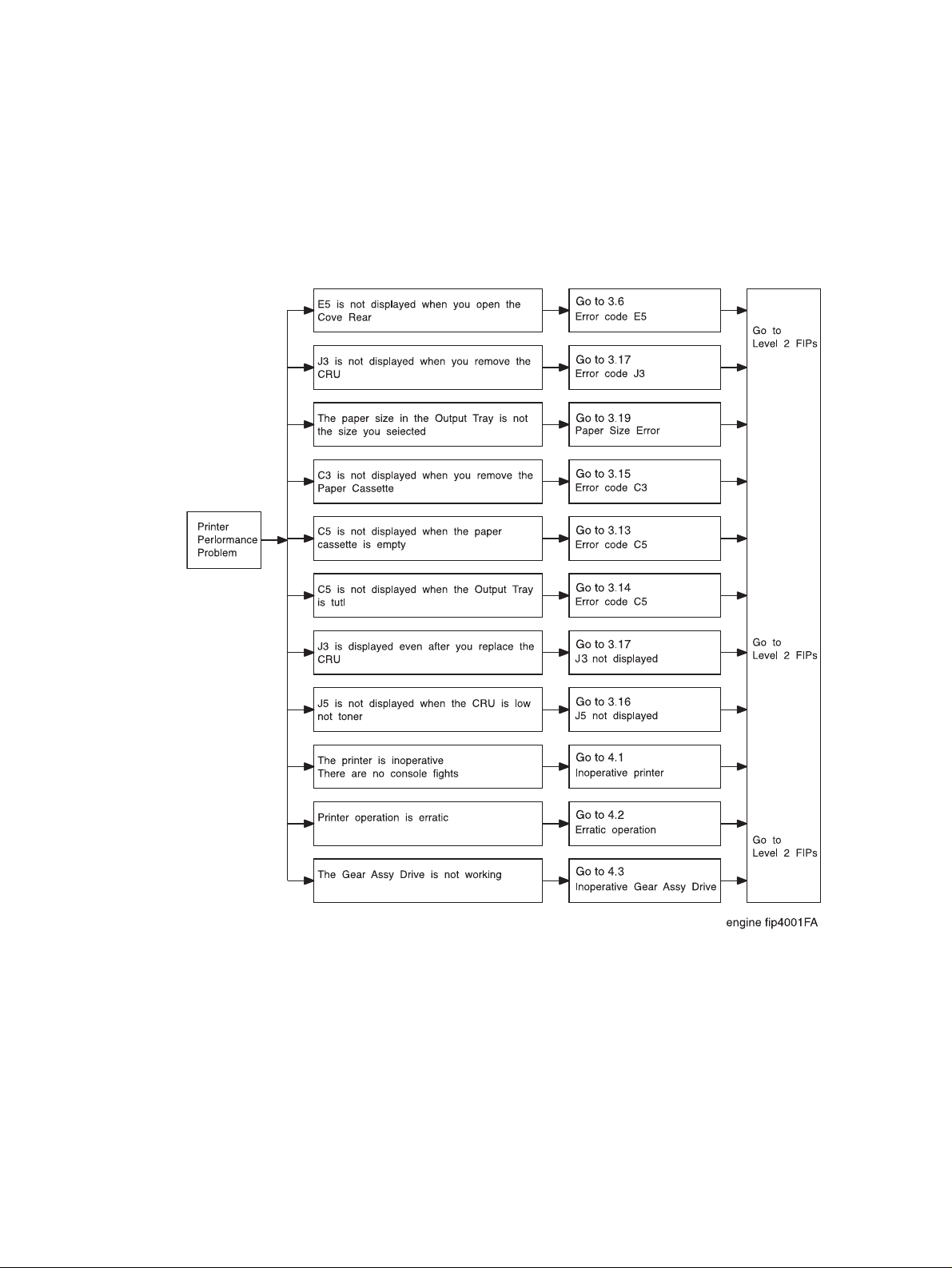
Primary FIPs:Printer Perfomance Problems
Printer Performance Problems Flow Chart
The FIP Flowchart should have directed you to this section. Start at your problem box, then follow the
arrow leading to the individual FIP that corresponds to that problem.
HAKUBA 26PPM Laser Printer - Base Engine Technical Manual 4-3
Version 1.0
Page 62

Primary FIPs:Printer Perfomance Problems
4.1 Inoperative Printer
Step Actions and Questions Yes No
1
2
3
INITIAL ANALYSIS
Inspect the following components.
• Co0ntrol Assy Panel (PL1.1.6)
• PWB ESS (PL10.1.2)
• PWBA HKB PS (PL10.1.17)
• PWBA HKB26 MCU (PL10.1.13)
• PWBA HVPS (PL10.1.20)
• Fan Assy (PL9.1.7)
• Solenoid Pick Up (PL4.1.23)
• Clutch Regi (5.1.19)
• Clutch Assy Feed (PL3.1.37)
• Clutch Assy Turn (PL3.1.2)
• Motor Assy Main (PL8.1.14)
• Sensor Assy Toner (PL5.1.1)
CONTROL ASSY PANEL (PL1.1.6) ANALYSIS
1. Disconnect P/J 362 on the PWBA ESS.
2. Switch ON the Main Power.
Does the Fan Assy function normally?
PWB ESS (PL10.1.2) ANALYSIS
1. Unplug the interface cable between the PWB ESS and the
PWBA HKB26 MCU.
Go to step 2. Replace the
problem components.
Replace the
Control Assy
Panel
(RRP1.1.5).
Replace the
PWB ESS
(RRP10.1.1).
Go to step 3.
Go to step 4.
2. Switch ON the Main Power.
Does the Fan Assy function normally?
4
4-4 HAKUBA 26PPM Laser Printer - Base Engine Technical Manual
PWBA HKB PS (PL10.1.17) ANALYSIS
1. Disconnect P/J28 on the PWBA HKB26 MCU.
2. Switch ON the Main Power.
3. Read voltage within 30 seconds after switching on the Main
Power.
Are the following voltages present on the pins of J28?
Is there +3.3VDC between J28-10 and J28-8?
Is there+5VDC between J28-7 and J28-8?
Is there +24VDC between J28-1 and J28-8?
Is there +24VDC between J28–2 and J28-8?
Is there +24VDC between J28-1 and J28-8?
Go to step 5. Replace the
PWBA HKB
PS
(RRP10.1.9).
Version 1.0
Page 63

Primary FIPs:Printer Perfomance Problems
4.1 Inoperative Printer continued
Step Actions and Questions Yes No
5
6
7
8
9
PWBA HVPS(PL10.1.20) ANALYSIS
Unplug P/J11 on the PWBA HVPS.
Switch ON Main Power.
Does the Fan function normally?
FAN ASSY (PL9.1.7) ANALYSIS
Unplug P/J283 on the PWBA HKB26 MCU.
Switch ON Main Power.
Check the voltage between P283-1 and P283-3.
Is there +24VDC between P283-1 and P283-3?
CLUTCH ASSY FEED (PL3.1.37) ANALYSIS
Disconnect P/J65 from the PWBA Feeder.
Switch ON Main Power.
Does the Fan function normally?
CLUTCH ASSY TURN (PL3.1.2) ANALYSIS
Disconnect P/J64 from the PWBA Feeder.
Switch ON Main Power.
Does the Fan function normally?
MOTOR ASSY (PL2.2.22) ANALYSIS
Disconnect P/J67 from the PWBA Feeder.
Switch ON Main Power.
Does the Fan function normally?
Replace the
PWBA HVPS
(RRP10.1.11)
Replace the
Fan Assy
(RRP9.1.2)
Replace the
Clutch Assy
Feeder
(RRP3.1.8)
Replace the
Clutch Assy
Turn
(PL3.1.2)
Replace the
Motor Assy
(RRP2.2.4)
Go to step 6
Go to step 7
Go to step 8
Go to step 9
Go to step 10
10
11
12
HAKUBA 26PPM Laser Printer - Base Engine Technical Manual 4-5
Version 1.0
SOLENOID PICK UP (PL4.1.23) ANALYSIS
Disconnect P/J44 from the PWBA Feeder.
Switch ON Main Power.
Does the Fan function normally?
CLUTCH REGI (PL5.1.19) ANALYSIS
Disconnect P/J43 from the PWBA Feeder.
Switch ON Main Power.
Does the Fan function normally?
MOTOR ASSY MAIN (PL8.1.14) ANALYSIS
Disconnect P/J 29 from the PWB HKB MCU.
Switch ON Main Power.
Does the Fan function normally?
Replace the
Solenoid Pick
Up
(RRP4.1.8)
Replace the
Clutch Regi
(RRP5.1.9)
Replace the
Motor Assy
Main
(RRP8.1.4)
Go to step 11
Go to step 12
Go to step 13
Page 64

Primary FIPs:Printer Perfomance Problems
4.1 Inoperative Printer continued
Step Actions and Questions Yes No
13
14
TONER SENSOR (PL5.1.1) ANALYSIS
Disconnect P/J 42 from the PWBA Conn.
Switch ON Main Power.
Does the Fan function normally?
ROS ASSY (PL8.1.9) ANALYSIS
Unplug P/J21 from the PWBA HKB26 MCU.
Switch ON Main Power
Does the Fan function normally?
Replace the
Toner Sensor
(RRP5.1.11)
Replace the
ROS Assy
(RRP8.1.2)
Go to step 14
Replace the
PWBA HKB26
MCU
(RRP10.1.7)
4-6 HAKUBA 26PPM Laser Printer - Base Engine Technical Manual
Version 1.0
Page 65

Primary FIPs:Printer Perfomance Problems
4.2 Erratic Operation
Step Actions and Questions Yes No
1
2
3
4
5
INITIAL ANALYSIS
Inspect the following components.
• PWBA HKB26 MCU (PL10.1.3)
• PWBA HVPS (PL10.1.20)
• PWBA HKB PS (PL10.1.17)
Are they compatible with your printer version, correctly
installed, not damaged, deformed, or contaminated?
Does the printer enter a print cycle? Go to step 3 Go to step 4
Enter DIAGNOSTIC MODE MENU.
Can you enter the DIAGNOSTIC MODE MENUE?
Does the printer RESET while it is making a test print? Go to 6.22
Install a new PWBA HKB26 MCU.
Does erratic operation still occur?
Go to step 2 Replace the
problem components
Go to step 5 Replace the
PWBA HKB26
MCU
(RRP10.1.7)
Go to step 5
Electrical
Noise
Replace the
PWB ESS
(RRP10.1.1)
Problem
solved
HAKUBA 26PPM Laser Printer - Base Engine Technical Manual 4-7
Version 1.0
Page 66

Primary FIPs:Printer Perfomance Problems
4.3 Inoperative Drive Components
Step Actions and Questions Yes No
1
2
3
INITIAL ANALYSIS
Inspect the following components.
• Gear Assy Drive (PL8.1.13)
• Motor Assy Main (PL8.1.14)
• PWBA HKB PS (PL10.1.17)
• PWBA HKB26 MCU (PL10.1.13)
Are they compatible with your printer version, correctly
installed, not damaged, deformed, or contaminated?
GEAR ASSY DRIVE (PL8.1.13) ANALYSIS
Use MAIN MOTOR TEST to check the Gear Assy Drive function.
Do the Gear Assy Drive rotate smoothly?
MOTOR ASSY MAIN (PL8.1.14) ANALYSIS
Use MAIN MOTOR TEST to check the Motor Assy Main function.
Does the Motor Assy Main function correctly?
Go to step 2 Replace the
problem components
Go to step 3 Replace the
Gear Assy
Drive
(RRP8.1.3)
Replace the
PWBA HKB26
MCU
(RRP10.1.7)
Go to 7.16
Drive Components Failure
4-8 HAKUBA 26PPM Laser Printer - Base Engine Technical Manual
Version 1.0
Page 67

Blank Page
Primary FIPs:Printer Perfomance Problems
HAKUBA 26PPM Laser Printer - Base Engine Technical Manual 4-9
Version 1.0
Page 68

Primary FIPs:Printer Perfomance Problems
4-10 HAKUBA 26PPM Laser Printer - Base Engine Technical Manual
Version 1.0
Page 69

Primary FIPs:Image Quality Problems
Section 5 Primary FIPs:Image Quality Problems Contents
5.1 Light (Undertoned) Prints . . . . . . . . . . . . . . . . . . . . . . . . . . . . . . . . . . . . . . . . . . . . . . . . . . . . . . . 5-5
5.2 Blank Prints . . . . . . . . . . . . . . . . . . . . . . . . . . . . . . . . . . . . . . . . . . . . . . . . . . . . . . . . . . . . . . . . . 5-7
5.3 Black Prints . . . . . . . . . . . . . . . . . . . . . . . . . . . . . . . . . . . . . . . . . . . . . . . . . . . . . . . . . . . . . . . . . 5-9
5.4 Vertical Band Deletions . . . . . . . . . . . . . . . . . . . . . . . . . . . . . . . . . . . . . . . . . . . . . . . . . . . . . . . 5-10
5.5 Vertical Linear Deletions. . . . . . . . . . . . . . . . . . . . . . . . . . . . . . . . . . . . . . . . . . . . . . . . . . . . . . . 5-11
5.6 Horizontal Band Deletions . . . . . . . . . . . . . . . . . . . . . . . . . . . . . . . . . . . . . . . . . . . . . . . . . . . . . 5-12
5.7 Vertical Streaks . . . . . . . . . . . . . . . . . . . . . . . . . . . . . . . . . . . . . . . . . . . . . . . . . . . . . . . . . . . . . 5-14
5.8 Horizontal Steaks . . . . . . . . . . . . . . . . . . . . . . . . . . . . . . . . . . . . . . . . . . . . . . . . . . . . . . . . . . . 5-15
5.9 Spot Deletions . . . . . . . . . . . . . . . . . . . . . . . . . . . . . . . . . . . . . . . . . . . . . . . . . . . . . . . . . . . . . . 5-16
5.10 Spots . . . . . . . . . . . . . . . . . . . . . . . . . . . . . . . . . . . . . . . . . . . . . . . . . . . . . . . . . . . . . . . . . . . . 5-17
5.11 Residual Image . . . . . . . . . . . . . . . . . . . . . . . . . . . . . . . . . . . . . . . . . . . . . . . . . . . . . . . . . . . . 5-18
5.12 Background . . . . . . . . . . . . . . . . . . . . . . . . . . . . . . . . . . . . . . . . . . . . . . . . . . . . . . . . . . . . . . . 5-19
5.13 Skewed Image . . . . . . . . . . . . . . . . . . . . . . . . . . . . . . . . . . . . . . . . . . . . . . . . . . . . . . . . . . . . . 5-20
5.14 Damaged Prints . . . . . . . . . . . . . . . . . . . . . . . . . . . . . . . . . . . . . . . . . . . . . . . . . . . . . . . . . . . . 5-21
5.15 Unfused Image . . . . . . . . . . . . . . . . . . . . . . . . . . . . . . . . . . . . . . . . . . . . . . . . . . . . . . . . . . . . 5-22
5.16 Misregistered Image . . . . . . . . . . . . . . . . . . . . . . . . . . . . . . . . . . . . . . . . . . . . . . . . . . . . . . . . 5-23
HAKUBA 26PPM Laser Printer - Base Engine Technical Manual 5-1
Version 1.0
Page 70

Primary FIPs:Image Quality Problems
Blank Page
5-2 HAKUBA 26PPM Laser Printer - Base Engine Technical Manual
Version 1.0
Page 71

Primary FIPs:Image Quality Problems
Image Quality Problems
The FIP Flowchart or a Level 1 FIP should have directed you to this section.
Before entering the Image Quality FIPs, make sure:
1. Is the printer plugged into a recommended AC wall outlet?
2. Is the AC power provided at the wall outlet within recommended specifications?
3. Is the AC power cord connected to the printer.
4. Is the AC power cord in good condition; not frayed or broken?
5. Is the printer properly grounded through the AC wall outlet?
6. Is the printer located in an area where the temperature and humidity are moderate and stable?
7. Is the printer located in an area that is free of dust?
8. Is the printer located in an area away from water outlets, steamers, electric heaters, volatile gases, or
open flames?
9. Is the printer shielded from the direct rays of the sun?
10. Does the printer have recommended space around all sides for proper ventilation?
11. Is the printer sitting on a level and stable surface?
12. Is recommended paper stock being used in the printer?
13. Does the customer use the printer as instructed in the HAKUBA User Manual?
14. Are consumables, such as the CRU, replaced at recommended intervals?
HAKUBA 26PPM Laser Printer - Base Engine Technical Manual 5-3
Version 1.0
Page 72

Primary FIPs:Image Quality Problems
Use Letter–size or A4 paper when troubleshooting an image quality problem.
Image Quality FIPs assume there is no malfunction of the printer controller. Use Printing Test Mode to
determine whether an image quality problem is being caused by the printer engine or by the printer controller. The printer engine generates the test print. If the test print is normal, but the regular prints have a
image quality problem, the problem may be with the printer controller.
If you are unable to solve the image problem using the Image Quality FIPs, we recommend that you
replace the printer controller with a known good controller. If the problem still persists, we recommend you
replace each component listed in Initial Analysis of the problem FIP, one by one, until you solve the problem.
5-4 HAKUBA 26PPM Laser Printer - Base Engine Technical Manual
Version 1.0
Page 73

engine fip5001FA
Primary FIPs:Image Quality Problems
5.1 Light (Undertoned) Prints
PROBLEM
The overall image density is too light.
INITIAL ANALYSIS
1. Inspect the following components. Are they compatible with your printer
version, correctly installed, not damaged, deformed, or contaminated?
• CRU • HVPS
•Spring Clip •BTR Assy
• Chute Trans Assy • ROS Assy
• PWB HKB26 MCU • Harness Assy Conn (J23-J231)
• PWBA HKB PS • Fuser Assy
• Harness Assy Fuser-M (J271, J11, J27, J262)
• Cover Assy Front
2. Inspect the printer paper path. Is it clear of foreign matter such as staples,
paper clips, and paper scrap?
Step Actions and Questions Yes No
1
2
3
4
PAPER CONDITIONS
Is there moisture in the paper?
DRUM GROUND
Check the Drum Ground Path:
Drum>Drum Shaft Pin>Spring Clip > Frame.
Is the Drum Ground Path complete?
LASER BEAM PATH
Inspect the laser beam path, between the ROS Assy and the
Drum, for contamination or obstructions.
Is the laser beam path free of obstacles?
BTR ASSY
Inspect the BTR Assy for contamination.
Is the BTR free of contamination?
Load fresh,
dry paper.
Go to step 3 Re-establish
Go to step 4 Remove
Go to step 5 Replace the
Go to step 2
the Drum
Ground Path
obstructions
or contamination.
BTR Assy
HAKUBA 26PPM Laser Printer - Base Engine Technical Manual 5-5
Version 1.0
Page 74

Primary FIPs:Image Quality Problems
5.1 Light (Undertoned) Prints continued
Step Actions and Questions Yes No
5
6
IMAGE TRANSFER PROCESS FAILURE
Generate a test print and switch OFF printer power halfway
through the print cycle.
Remove the CRU and inspect the toner image on the drum.
Was the image on the drum transferred completely to the
paper?
CRU FAILURE
Install a new CRU.
Is the problem solved?
Go to step 6 Go to 6.19
HVPS Failure
Problem
solved
Return to Initial Analysis
5-6 HAKUBA 26PPM Laser Printer - Base Engine Technical Manual
Version 1.0
Page 75

Primary FIPs:Image Quality Problems
5.2 Blank Prints
PROBLEM
The entire print is blank.
INITIAL ANALYSIS
1. Inspect the following components. Are they compatible with your printer
version, correctly installed, not damaged, deformed, or contaminated?
• CRU • PWBA HVPS
•BTR Assy •ROS Assy
• P/H Assy • PWBA HKB26 MCU
• Harness Assy Conn (J23-J231)
• PWBA HKB PS
• Fuser Assy • Cover Assy Front
• Harness Assy Fuser (J271, J11, J27, J262)
2. Inspect the printer paper path. Is it clear of foreign matter such as staples,
paper clips, and paper scrap?
Step Actions and Questions Yes No
1
2
3
4
DRUM GROUND
Check the Drum Ground Path:
Drum>Drum Shaft Pin >Spring Clip > Frame.
Is the Drum Ground Path complete?
LASER BEAM PATH
Inspect the laser beam path, between the ROS Assy and the
Drum, for contamination or obstructions.
Is the laser beam path free of obstacles?
BTR ASSY
Inspect the BTR Assy for contamination.
Is the BTR free of contamination?
IMAGE TRANSFER PROCESS FAILURE
Generate a test print and switch OFF printer power halfway
through the print cycle.
Remove the CRU and inspect the image on the drum.
Was the image on the drum transferred to the paper?
Go to step 2 Re-establish
the Drum
Ground Path
Go to step 3 Remove
obstructions
or contamination.
Go to step 4. Replace the
BTR Assy
Go to step 5 Go to 6.19
PWBA HVPS
Failure
HAKUBA 26PPM Laser Printer - Base Engine Technical Manual 5-7
Version 1.0
Page 76

Primary FIPs:Image Quality Problems
5.2 Blank Prints continued
Step Actions and Questions Yes No
5
CRU FAILURE
Install a new CRU.
Is the problem solved?
Problem
solved
Return to Initial Analysis
5-8 HAKUBA 26PPM Laser Printer - Base Engine Technical Manual
Version 1.0
Page 77

Primary FIPs:Image Quality Problems
5.3 Black Prints
PROBLEM
The entire print is black.
INITIAL ANALYSIS
1. Inspect the following components. Are they compatible with your printer
version, correctly installed, not damaged, deformed, or contaminated?
• CRU • PWBA HVPS
•Spring Clip •ROS Assy
• PWBA HKB26 MCU • Harness Assy HVPS (J26-J261)
2. Inspect the printer paper path. Is it clear of foreign matter such as staples,
paper clips, and paper scrap?
Step Actions and Questions Yes No
1
2
3
HVPS CR
Use a sheet of paper to cover the laser beam window.
Generate a test print.
Is the problem still present?
ROS ASSY FAILURE
Use a sheet of paper to cover HALF of the laser beam window.
Generate a test print.
Is the problem still present only
CRU FAILURE
Install a new CRU.
Is the problem solved?
on the uncovered half?
Go to step 2 Go to 6.19
PWBA HVPS
Failure
Go to step 3 Go to 6.3
ROS Assy
Failure
Problem
solved
Return to Initial Analysis
HAKUBA 26PPM Laser Printer - Base Engine Technical Manual 5-9
Version 1.0
Page 78

Primary FIPs:Image Quality Problems
5.4 Vertical Band Deletions
PROBLEM
There are areas of the image that are extremely light or missing entirely.
These missing areas form wide bands that run vertically along the page, in
the direction of paper travel.
INITIAL ANALYSIS
1. Inspect the following components. Are they compatible with your printer
version, correctly installed, not damaged, deformed, or contaminated?
• CRU • PWBA HKB26 MCU
•Fuser Assy •BTR Assy
• ROS Assy
engine fip5002FA
2. Inspect the printer paper path. Is it clear of foreign matter such as staples,
paper clips, and paper scrap?
Step Actions and Questions Yes No
1
2
3
4
PAPER CONDITIONS
Is there moisture in the paper?
Is the paper wrinkled?
LASER BEAM PATH
Inspect the laser beam path, between the ROS Assy and the
Drum, for contamination or obstructions.
Is the laser beam path free of obstacles?
BTR Assy
Inspect the BTR Assy for contamination.
Is the BTR free of contamination?
CRU FAILURE
Install a new CRU.
Is the problem solved?
Replace with
fresh, dry
paper
Go to step 3 Remove
Go to step 4 Replace the
Problem
solved
Go to step 2
obstructions
or contamination.
BTR Assy.
Return to Initial Analysis
5-10 HAKUBA 26PPM Laser Printer - Base Engine Technical Manual
Version 1.0
Page 79

engine fip5003FA
Primary FIPs:Image Quality Problems
5.5 Vertical Linear Deletions
PROBLEM
There are areas of the image that are extremely light or missing entirely.
These missing areas form narrow lines running vertically along the pages, in
the direction of paper travel.
INITIAL ANALYSIS
1. Inspect the following components. Are they compatible with your printer
version, correctly installed, not damaged, deformed, or contaminated?
• CRU • PWBA HKB26 MCU
• BTR Assy • BTR Chute Assy
• Heat Roll • Pressure Roll Assy
• Fuser Assy • ROS Assy
2. Inspect the printer paper path. Is it clear of foreign matter such as staples,
paper clips, and paper scrap?
Step Actions and Questions Yes No
Go to step 2 Remove
obstructions
or contamination.
Go to step 3 Replace the
BTR Assy
Problem
solved
Go to step 5 Replace the
Return to Initial Analysis
Go to step 4
Heat Roll
Remove
obstructions
or contamination from the
paper path.
1
2
3
4
5
LASER BEAM PATH
Inspect the laser beam path, between the ROS Assy and the
Drum, for contamination or obstructions.
Is the laser beam path free of obstacles?
BTR Assy
Inspect the BTR Assy for contamination.
Is the BTR free of contamination?
CRU FAILURE
Replace the CRU with a new one.
Is the problem solved?
HEAT ROLL DAMAGE
Inspect the Heat Roll for scratches, objects, or contamination.
Is the Heat Roll free of scratches and contamination?
PAPER PATH
Inspect the paper path, between feed and exit, for contamination or obstructions.
Is the paper path free of obstructions?
HAKUBA 26PPM Laser Printer - Base Engine Technical Manual 5-11
Version 1.0
Page 80

Primary FIPs:Image Quality Problems
5.6 Horizontal Band Deletions
PROBLEM
There are areas of the image that are extremely light or missing entirely.
These missing areas form wide bands that run horizontally across the page,
parallel with the direction of paper travel.
INITIAL ANALYSIS
1. Inspect the following components. Are they compatible with your printer
version, correctly installed, not damaged, deformed, or contaminated?
• CRU • PWBA HKB26 MCU
• PWBA HVPS • Spring Clip
• BTR Assy • BTR Chute Assy
• Heat Roll • Pressure Roll Assy
engine fip5004FA
• Fuser Assy • ROS Assy
2. Inspect the printer paper path. Is it clear of foreign matter such as staples,
paper clips, and paper scrap?
Step Actions and Questions Yes No
PAPER CONDITIONS
1
2
3
4
Table continued
Is there moisture in the paper?
Is the paper wrinkled?
DRIVE COMPONENTS FAILURE
Use MAIN MOTOR TEST to check the Gear Assy Drive.
Are the Drive Assy gears turning the CRU gear?
BTR Assy
Inspect the BTR Assy for contamination.
Is the BTR free of contamination?
IMAGE TRANSFER PROCESS FAILURE
Generate a test print and switch OFF printer power halfway
through the print cycle.
Remove the CRU and inspect the toner image on the drum.
Was the image on the drum transferred completely to the
paper?
Replace with
fresh, dry
paper
Go to step 3 Go to 6.11
Go to step 4 Replace the
Go to step 5 Go to 6.19
Go to step 2
Drive Components Failure
BTR Assy
PWBA HVPS
Failure
5-12 HAKUBA 26PPM Laser Printer - Base Engine Technical Manual
Version 1.0
Page 81

Primary FIPs:Image Quality Problems
5.6 Horizontal Band Deletions continued
Step Actions and Questions Yes No
6
7
8
CRU FAILURE
Replace the CRU with a new one.
Is the problem solved?
HEAT ROLL DAMAGE
Do the band deletions occur at intervals of approximately
104 mm?
PRESSURE ROLL DAMAGE
Do the band deletions occur at intervals of approximately
94 mm?
Problem
solved
Clean or
replace the
Heat Roll
Clean or
replace the
Pressure Roll
Assy
Go to step 7
Go to step 8
Return to Initial Analysis
HAKUBA 26PPM Laser Printer - Base Engine Technical Manual 5-13
Version 1.0
Page 82

Primary FIPs:Image Quality Problems
5.7 Vertical Streaks
PROBLEM
There are black lines running vertically along the page.
INITIAL ANALYSIS
1. Inspect the following components. Are they compatible with your printer
version, correctly installed, not damaged, deformed, or contaminated?
• CRU • PWBA HKB26 MCU
• PWBA HVPS • Spring Clip
• BTR Assy • BTR Chute Assy
• Heat Roll • Pressure Roll Assy
• Fuser Assy • ROS Assy
engine fip5005FA
2. Inspect the printer paper path. Is it clear of foreign matter such as staples,
paper clips, and paper scrap?
Step Actions and Questions Yes No
1
2
3
4
5
LASER BEAM PATH
Inspect the laser beam path, between the ROS Assy and the
Drum, for contamination or obstructions.
Is the laser beam path free of obstacles?
BTR Assy
Inspect the BTR Assy for contamination.
Is the BTR free of contamination?
INCOMPLETE DISCHARGE PROCESS
Remove the CRU and leave the Cover Assy Front open.
Cheat the Switch Assy I/L Front and run MAIN MOTOR TEST.
Does the BTR function normally?
CRU FAILURE
Replace the CRU with a new one.
Is the problem solved?
HEAT ROLL DAMAGE
Do the streaks occur at intervals of approximately 104
mm?
Go to step 2 Remove
obstructions
or contamination.
Go to step 3 Replace the
BTR Assy
Go to Step 4 Replace the
BTR Chute
Assy
Problem
solved
Replace the
Heat Roll
Go to step 5
Return to Initial Analysis
5-14 HAKUBA 26PPM Laser Printer - Base Engine Technical Manual
Version 1.0
Page 83

Primary FIPs:Image Quality Problems
5.8 Horizontal Streaks
PROBLEM
There are black lines running horizontally across the page.
INITIAL ANALYSIS
1. Inspect the following components. Are they compatible with your printer
version, correctly installed, not damaged, deformed, or contaminated?
• CRU • PWBA HKB26 MCU
• PWBA HVPS • Spring Clip
• BTR Assy • BTR Chute Assy
• Heat Roll • Pressure Roll Assy
• Fuser Assy • ROS Assy
• Harness Assy Conn (J23-J231)• PWBA HKB PS
engine fip5006FA
2. Inspect the printer paper path. Is it clear of foreign matter such as staples,
paper clips, and paper scrap?
Step Actions and Questions Yes No
1
2
3
4
5
6
DRUM GROUND
Check the Drum Ground Path:
Drum>Drum Shaft Pin>Spring Clip > Frame.
Is the Drum Ground Path complete?
ROS Assy
Use a sheet of paper to cover the laser beam window.
Generate a test print.
Is the problem still present?
BTR Assy
Inspect the BTR Assy for contamination.
Is the BTR free of contamination?
CRU FAILURE
Replace the CRU with a new one.
Is the problem solved?
HEAT ROLL Assy
Inspect the Heat Roll for scratches, objects, or contamination.
Is the Heat Roll free of scratches and contamination?
NOISE
Go to 6.20 Electrical Noise for possible noise problem.
Go to step 2 Re-establish
the Drum
Ground Path
Go to step 3 Go to 6.3
ROS Assy
Failure
Go to step 4 Replace the
BTR Assy
Problem
solved
Go to step 6 Replace the
Go to step 5
Heat Roll
HAKUBA 26PPM Laser Printer - Base Engine Technical Manual 5-15
Version 1.0
Page 84

Primary FIPs:Image Quality Problems
5.9 Spot Deletions
PROBLEM
There are areas of the image that are extremely light or missing entirely.
These missing areas form spots that are localized to small areas of the page.
INITIAL ANALYSIS
1. Inspect the following components. Are they compatible with your printer
version, correctly installed, not damaged, deformed, or contaminated?
• CRU • BTR Assy
• Fuser Assy • Pressure Roll Assy
•Heat Roll
2. Inspect the printer paper path. Is it clear of foreign matter such as staples,
engine fip5007FA
paper clips, and paper scrap?
Step Actions and Questions Yes No
1
2
3
4
5
PAPER CONDITIONS
Is there moisture in the paper?
Is the paper wrinkled?
BTR Assy
Inspect the BTR Assy for contamination.
Is the BTR free of contamination?
CRU FAILURE
Replace the CRU with a new one.
Is the problem solved?
HEAT ROLL DAMAGE
Do the spot deletions occur at intervals of approximately
62.0mm?
PRESSURE ROLL DAMAGE
Do the spot deletions occur at intervals of approximately
61.0mm?
Replace with
fresh, dry
paper.
Go to step 3 Replace the
Problem
solved
Replace the
Heat Roll
Replace the
Pressure Roll
Assy
Go to step 2
BTR Assy
Go to step 4
Go to step 5
Return to Initial Analysis
5-16 HAKUBA 26PPM Laser Printer - Base Engine Technical Manual
Version 1.0
Page 85

Primary FIPs:Image Quality Problems
5.10 Spots
PROBLEM
There are spots of toner randomly scattered across the page.
INITIAL ANALYSIS
1. Inspect the following components. Are they compatible with your printer
version, correctly installed, not damaged, deformed, or contaminated?
• CRU • Fuser Assy
• Heat Roll • Pressure Roll Assy
•BTR Assy
engine fip5008FA
2. Inspect the printer paper path. Is it clear of foreign matter such as staples,
paper clips, and paper scrap?
Step Actions and Questions Yes No
1
2
3
4
BTR Assy
Inspect the BTR Assy for contamination.
Is the BTR free of contamination?
CRU FAILURE
Replace the CRU with a new one.
Is the problem solved?
HEAT ROLL DAMAGE
Do the spots occur at intervals of approximately 104mm?
PRESSURE ROLL DAMAGE
Do the spots occur at intervals of approximately 94mm?
Go to step 2 Replace the
Problem
solved
Replace the
Heat Roll
Replace the
Pressure Roll
Assy
BTR Assy
Go to step 3
Go to step 4
Return to Initial Analysis
HAKUBA 26PPM Laser Printer - Base Engine Technical Manual 5-17
Version 1.0
Page 86

Primary FIPs:Image Quality Problems
5.11 Residual Image
PROBLEM
There are ghost images appearing on the page. The images may be either
ghosts of the previous page or parts of the page currently being printed.
INITIAL ANALYSIS
1. Inspect the following components. Are they compatible with your printer
version, correctly installed, not damaged, deformed, or contaminated?
• CRU • BTR Assy
• Heat Roll • Pressure Roll Assy
• Fuser Assy
engine fip5009FA
2. Inspect the printer paper path. Is it clear of foreign matter such as staples,
paper clips, and paper scrap?
Step Actions and Questions Yes No
1
2
3
4
5
PAPER CONDITIONS
Is there moisture in the paper?
Is the paper wrinkled?
BTR Assy
Inspect the BTR Assy for contamination.
Is the BTR free of contamination?
CRU FAILURE
Replace the CRU with a new one.
Is the problem solved?
HEAT ROLL DAMAGE
Do the images occur at intervals of approximately
62.0mm?
PRESSURE ROLL DAMAGE
Do the images occur at intervals of approximately
61.0mm?
Replace with
fresh, dry
paper.
Go to step 3 Replace the
Problem
solved
Go to step 5 Replace the
Replace the
Pressure Roll
Assy
Go to step 2
BTR Assy
Go to step 4
Heat Roll
Return to Initial Analysis
5-18 HAKUBA 26PPM Laser Printer - Base Engine Technical Manual
Version 1.0
Page 87

engine fip5010FA
Primary FIPs:Image Quality Problems
5.12 Background
PROBLEM
There is toner contamination on all or part of the page. The contamination
appears as a very light gray dusting.
INITIAL ANALYSIS
1. Inspect the following components. Are they compatible with your printer
version, correctly installed, not damaged, deformed, or contaminated?
• CRU • HVPS
• Spring Clip • PWBA HKB26 MCU
• Harness Assy Conn • PWBA HKB PS
• ROS Assy • Fuser Assy
2. Inspect the printer paper path. Is it clear of foreign matter such as staples,
paper clips, and paper scrap?
Step Actions and Questions Yes No
1
2
3
HVPS CR
Use a sheet of paper to cover the laser beam window.
Generate a test print.
Is the problem still present?
CRU
Install a new CRU.
Is the background still on the page?
FUSER GROUND PATH
Inspect the Fuser Ground Path within the Fuser Assy and from
the Fuser Assy to the Frame Ground.
Is the Fuser Ground Path functioning correctly?
Go to step 2 Go to 6.19
PWBA HVPS
Failure
Problem
solved
Return to Initial Analysis
Go to step 3
Re-establish a
fuser ground
path.
HAKUBA 26PPM Laser Printer - Base Engine Technical Manual 5-19
Version 1.0
Page 88

Primary FIPs:Image Quality Problems
5.13 Skewed Image
PROBLEM
The printed image is not parallel with the sides of the page.
INITIAL ANALYSIS
1. Inspect the following components. Are they compatible with your printer
version, correctly installed, not damaged, deformed, or contaminated?
• CRU • BTR Assy
• BTR Chute Assy • P/H Assy
• Roll Assy MBF • Feeder Assy
• Cassette Assy • Plate Assy Bottom
• Main Tray • Retard Pad
engine fip5011FA
• ROS Assy
2. Inspect the printer paper path. Is it clear of foreign matter such as staples,
paper clips, and paper scrap?
Step Actions and Questions Yes No
1
2
3
4
PAPER FEED
Are the paper cassettes installed correctly, and is the
paper correctly loaded into the cassette?
CRU
Install a new CRU.
Is the image still skewed?
PAPER PATH
Inspect the paper path, between the feed tray and the exit tray,
for contamination or obstructions.
Is the paper path free of obstructions?
PAPER PATH ROLLS
Inspect the rolls along the paper path, between the feed tray
and the exit tray, for contamination, scratches, or damage.
Are the paper path rolls free of contamination, scratches,
or damage?
Go to step 2 Reload the
paper and
reinstall the
cassettes.
Go to step 3 Problem
solved
Go to step 4 Remove
obstructions
or contamination from the
paper path.
Return to Initial Analysis
Replace the
damaged roll.
5-20 HAKUBA 26PPM Laser Printer - Base Engine Technical Manual
Version 1.0
Page 89

Primary FIPs:Image Quality Problems
5.14 Damaged Prints
PROBLEM
The printed page comes out of the printer either wrinkled, creased, or torn.
INITIAL ANALYSIS
1. Inspect the following components. Are they compatible with your printer
version, correctly installed, not damaged, deformed, or contaminated?
• Fuser Assy • Pressure Roll Assy
•Heat Roll
2. Inspect the printer paper path. Is it clear of foreign matter such as staples,
paper clips, and paper scrap?
engine fip5012FA
Step Actions and Questions Yes No
1
2
3
4
5
6
PAPER CONDITIONS
Is there moisture in the paper?
Is the paper wrinkled?
HEAT ROLL DAMAGE
Inspect the Heat Roll for scratches, objects, or contamination.
Is the Heat Roll free of scratches and contamination?
PRESSURE ROLL DAMAGE
Inspect the Pressure Roll for scratches, objects, or contamination.
Is the Heat Roll free of scratches and contamination?
SKEWED IMAGE
Inspect the print.
Is the print image skewed?
PAPER PATH
Inspect the paper path, between the feed tray and the exit tray,
for contamination or obstructions.
Is the paper path free of obstructions?
PAPER PATH ROLLS
Inspect the rolls along the paper path, between the feed tray
and the exit tray, for contamination, scratches, or damage.
Are the paper path rolls free of contamination, scratches,
or damage?
Replace with
fresh, dry
paper.
Go to step 3 Replace the
Go to step 4 Replace the
Go to 8.13
Skewed
Image
Go to step 6 Remove
Return to Initial Analysis
Go to step 2
Heat Roll
Pressure Roll
Assy
Go to step 5
obstructions
or contamination from the
paper path.
Replace the
problem roller
Assy
HAKUBA 26PPM Laser Printer - Base Engine Technical Manual 5-21
Version 1.0
Page 90

Primary FIPs:Image Quality Problems
5.15 Unfused Image
PROBLEM
The printed image is not fully fused to the paper. The image easily
rubs off.
INITIAL ANALYSIS
1.Inspect the following components. Are they compatible with your
printer version, correctly installed, not damaged, deformed, or contaminated?
•PWBA HKB26 MCU • Fuser Assy
•Heat Roll • Pressure Roll Assy
•PWBA HKB PS
engine fip5013FA
2.Inspect the printer paper path. Is it clear of foreign matter such as
staples, paper clips, and paper scrap?
Step Actions and Questions Yes No
1
2
3
4
PAPER CONDITIONS
Is there moisture in the paper?
Is the paper wrinkled?
CAP ENVELOP
Open the Cover Rear.
Inspect the Cap Envelop (PL1.2.7).
Is the Cap Envelop (PL1.2.7) set properly?
HEAT ROLL
Inspect the Heat Roll for scratches, objects, or contamination.
Is the Heat Roll free of scratches and contamination?
PRESSURE ROLL
Inspect the Pressure Roll for scratches, objects, or contamination.
Is the Pressure Roll free of scratches and contamination?
Replace with
fresh, dry
paper.
Go to step 3 Recover the
Go to step 4 Replace the
Go to step 5 Replace the
Go to step 2
NIP of the
Fuser Assy
Heat Roll
Pressure Roll
Assy
FUSER Assy
5
5-22 HAKUBA 26PPM Laser Printer - Base Engine Technical Manual
Inspect the contact between the Heat and Pressure Rolls.
Are the Heat and Pressure Rolls contacting correctly?
Return to Initial Analysis
Replace the
Fuser Assy
Version 1.0
Page 91

Primary FIPs:Image Quality Problems
5.16 Misregistered Image
PROBLEM
The printed image is not centered on the page or is bleeding off of the page.
INITIAL ANALYSIS
1. Inspect the following components. Are they compatible with your printer
version, correctly installed, not damaged, deformed, or contaminated?
• CRU • BTR Assy
• BTR Chute Assy • P/H Assy
• Roll Assy MBF • Feeder Assy
• Cassette Assy • Plate Assy Bottom
engine fip5014FA
• Main Tray • Retard Pad
• ROS Assy
2. Inspect the printer paper path. Is it clear of foreign matter such as staples,
paper clips, and paper scrap?
Step Actions and Questions Yes No
1
2
PAPER CONDITIONS
Is there moisture in the paper?
Is the paper wrinkled?
SKEWED IMAGE
Inspect the print.
Is the print image skewed?
REGISTRATION ADJUSTMENT
Generate a test print. Inspect the print.
Replace with
fresh, dry
paper.
Go to 8.13
Skewed
Image
Go to step 4 Check the
3
Is the test print misregistered?
Go to step 2
Go to step 3
application
software
printer settings.
Replace the
PWB ESS.
CONFIGURATION MODE
Attach the Diagnostic Commander to the printer and enter
4
HAKUBA 26PPM Laser Printer - Base Engine Technical Manual 5-23
Version 1.0
Configuration Mode (Appendix B).
Check NV codes 03 through 08, and 0D through 0I.
Are the NV codes set at the default values?
Go to step 5 Set the NV
values to the
default values, and
return to step
3.
Page 92

Primary FIPs:Image Quality Problems
5.16 Misregistered Image continued
Step Actions and Questions Yes No
5
6
PAPER PATH
Inspect the paper path, between the feed tray and the exit tray,
for contamination or obstructions.
Is the paper path free of obstructions?
PAPER PATH ROLLS
Inspect the rolls along the paper path, between the feed tray
and the exit tray, for contamination, scratches, wear, or damage.
Are the paper path rolls free of contamination, scratches,
wear, or damage?
Go to step 6 Remove
obstructions
or contamination from the
paper path.
Return to Initial Analysis
Replace the
problem roller
Assy
5-24 HAKUBA 26PPM Laser Printer - Base Engine Technical Manual
Version 1.0
Page 93

Secondary FIPs
Section 6 Secondary FIPs Contents
6.1 PWBA HKB PS Failure (+3.3VDC) . . . . . . . . . . . . . . . . . . . . . . . . . . . . . . . . . . . . . . . . . . . . . . . 6-4
6.2 PWBA HKB PS Failure (+24VDC) . . . . . . . . . . . . . . . . . . . . . . . . . . . . . . . . . . . . . . . . . . . . . . . . 6-5
6.3 ROS Assy Failure. . . . . . . . . . . . . . . . . . . . . . . . . . . . . . . . . . . . . . . . . . . . . . . . . . . . . . . . . . . . . 6-6
6.4 Heat Rod Failure . . . . . . . . . . . . . . . . . . . . . . . . . . . . . . . . . . . . . . . . . . . . . . . . . . . . . . . . . . . . . 6-8
6.5 Temperature Sensor Failure . . . . . . . . . . . . . . . . . . . . . . . . . . . . . . . . . . . . . . . . . . . . . . . . . . . . 6-10
6.6 Sensor Exit Failure . . . . . . . . . . . . . . . . . . . . . . . . . . . . . . . . . . . . . . . . . . . . . . . . . . . . . . . . . . . 6-11
6.7 Sensor Photo: Regi Failure . . . . . . . . . . . . . . . . . . . . . . . . . . . . . . . . . . . . . . . . . . . . . . . . . . . . 6-12
6.8 Sensor Photo:No Pap 1 Failure . . . . . . . . . . . . . . . . . . . . . . . . . . . . . . . . . . . . . . . . . . . . . . . . . 6-13
6.9 Sensor Photo: Exit Failure . . . . . . . . . . . . . . . . . . . . . . . . . . . . . . . . . . . . . . . . . . . . . . . . . . . . . 6-15
6.10 Sensor Assy CRU Failure . . . . . . . . . . . . . . . . . . . . . . . . . . . . . . . . . . . . . . . . . . . . . . . . . . . . 6-16
6.11 Drive Components Failure . . . . . . . . . . . . . . . . . . . . . . . . . . . . . . . . . . . . . . . . . . . . . . . . . . . . 6-17
6.12 Paper Size Sensor Failure . . . . . . . . . . . . . . . . . . . . . . . . . . . . . . . . . . . . . . . . . . . . . . . . . . . . 6-20
6.13 Solenoid Pick Up Failure . . . . . . . . . . . . . . . . . . . . . . . . . . . . . . . . . . . . . . . . . . . . . . . . . . . . . 6-21
6.14 Clutch Assy Feed Failure . . . . . . . . . . . . . . . . . . . . . . . . . . . . . . . . . . . . . . . . . . . . . . . . . . . . . 6-22
6.15 Clutch Assy Turn Failure . . . . . . . . . . . . . . . . . . . . . . . . . . . . . . . . . . . . . . . . . . . . . . . . . . . . . 6-23
6.16 Fan Assy Failure . . . . . . . . . . . . . . . . . . . . . . . . . . . . . . . . . . . . . . . . . . . . . . . . . . . . . . . . . . . 6-24
6.17 Toner Sensor Failure . . . . . . . . . . . . . . . . . . . . . . . . . . . . . . . . . . . . . . . . . . . . . . . . . . . . . . . . 6-25
6.18 Exit Failure . . . . . . . . . . . . . . . . . . . . . . . . . . . . . . . . . . . . . . . . . . . . . . . . . . . . . . . . . . . . . . . . 6-26
6.19 PWBA HVPS Failure . . . . . . . . . . . . . . . . . . . . . . . . . . . . . . . . . . . . . . . . . . . . . . . . . . . . . . . . 6-27
6.20 Electrical Noise. . . . . . . . . . . . . . . . . . . . . . . . . . . . . . . . . . . . . . . . . . . . . . . . . . . . . . . . . . . . . 6-28
HAKUBA 26PPM Laser Printer - Base Engine Technical Manual 6-1
Version 1.0
Page 94

Secondary FIPs
Blank Page
6-2 HAKUBA 26PPM Laser Printer - Base Engine Technical Manual
Version 1.0
Page 95

Secondary FIPs
Secondary FIPs
The 5.2 FIP Flowchart or a Level 1 FIP should have directed you to this section.
Before entering Level 2 FIPs, make sure:
1. Is the printer plugged into a recommended AC wall outlet?
2. Is the AC power provided at the wall outlet within recommended specifications?
3. Is the AC power cord connected to the printer.
4. Is the AC power cord in good condition; not frayed or broken?
5. Is the printer properly grounded through the AC wall outlet?
6. Is the printer located in an area where the temperature and humidity are moderate and stable?
7. Is the printer located in an area that is free of dust?
8. Is the printer located in an area away from water outlets, steamers, electric heaters, volatile gases, or
open flames?
9. Is the printer shielded from the direct rays of the sun?
10. Does the printer have recommended space around all sides for proper ventilation?
11. Is the printer sitting on a level and stable surface?
12. Is recommended paper stock being used in the printer?
13. Does the customer use the printer as instructed in the HAKUBA User Manual?
14. Are consumables, such as the CRU, replaced at recommended intervals?
HAKUBA 26PPM Laser Printer - Base Engine Technical Manual 6-3
Version 1.0
Page 96

Secondary FIPs
6.1 PWBA HKB PS Failure (+3.3 VDC)
Step Actions and Questions Yes No
1
2
INITIAL ANALYSIS
Inspect the following components.
• PWBA HKB26 MCU (PL10.1.13)
• PWBA HKB PS (PL10.1.17)
Are they compatible with your printer version, correctly
installed, not damaged, deformed, or contaminated?
PWBA HKB PS (PL10.1.17) ANALYSIS
Switch ON Main Power.
Take the following readings within 65 seconds after switching
ON Main Power.
Is there +3.3VDC between J282-1 and J282-2?
Go to step 2 Replace the
problem components
Replace the
PWBA HKB26
MCU
(RRP10.1.7)
Replace the
PWBA HKB
PS
(RRP10.1.9)
6-4 HAKUBA 26PPM Laser Printer - Base Engine Technical Manual
Version 1.0
Page 97

Secondary FIPs
6.2 LVPS Failure (+24VDC)
Step Actions and Questions Yes No
1
2
3
INITIAL ANALYSIS
Inspect the following components.
• PWBA HKB PS (PL10.1.17)
• PWBA HKB26 MCU (PL10.1.13)
Are they compatible with your printer version, correctly
installed, not damaged, deformed, or contaminated?
PWBA HKB PS (PL10.1.17) ANALYSIS
Switch ON Main Power.
Take the following readings within 65 seconds after switching
ON Main Power.
Is there +24VDC between P1–1 and P1–2 on the PWBA
HKB PS?
SWITCH ASSY I/L FRONT (PL10.1.12) ANALYSIS
Actuate the Switch Assy I/L Front.
Is there +5VDC between P288-1 and P288-2 on the PWBA
HKB 5VDC (PL10.1.14)?
Deactuate the Switch Assy I/L Front.
Is there +0VDC between P288-1 and P288-2 on the PWBA
HKB 5VDC?
Go to step 2 Replace the
problem components
Go to step 3 Replace the
PWBA HKB
PS
(RRP10.1.9)
Replace the
PWBA HKB26
MCU
(RRP10.1.7)
Replace the
PWBA HKB
5VDC
(RRP10.1.8)
HAKUBA 26PPM Laser Printer - Base Engine Technical Manual 6-5
Version 1.0
Page 98

Secondary FIPs
6.3 ROS Assy Failure
Step Actions and Questions Yes No
1
2
3
INITIAL ANALYSIS
Inspect the following components.
• PWBA HKB26 MCU (PL10.1.13)
• PWBA HKB PS (PL10.1.17)
• PWBA HKB 5VDC (PL10.1.14)
• ROS Assy (PL8.1.9)
• Harness Assy ROS (J21-J211, J212, J213) (PL8.1.7)
• Harness Assy VDO (J22-J223) (PL8.1.8)
Are they compatible with your printer version, correctly
installed, not damaged, deformed, or contaminated?
PWBA HKB PS (PL10.1.17) ANALYSIS
Switch ON Main Power.
Is there +5VDC between P281-7 and P281-8 on the on the
PWBA HKB 5VDC?
ROS MOTOR POWER SUPPLY ANALYSIS
Disconnect P/J21 from the PWBA HKB26 MCU.
Switch ON Main Power.
Determine the print resolution of the printer, and take the corresponding voltage readings between P21-11 and P21-10 on
the PWBA HKB26 MCU.
Is there +24VDC between P21-11 and P21-10?
Go to step 2 Replace the
problem components
Go to step 3 Replace the
PWBA HKB
PS
(RRP10.1.9)
Go to step 4 Replace the
PWBA HKB26
MCU
(RRP10.1.7)
4
5
6
6-6 HAKUBA 26PPM Laser Printer - Base Engine Technical Manual
SOS PWB POWER SUPPLY ANALYSIS
Is there +5VDC between P21-7 and P21-9 on the PWBA
HKB26 MCU?
Replace the PWBA HKB26 MCU.
Is the problem still present?
HARNESS ASSY ROS (J21-J211, J212, J213) (PL8.1.7)
ANALYSIS
Is there continuity (0Ω) between all wires on J21 and
J212?
Is there continuity (0Ω) between all wires on J21 and
J211?
Is there continuity (0Ω) between all wires on J21 and
J213?
Go to step 5 Replace the
PWBA HKB
5VDC
(RRP10.1.8)
Go to step 6 Problem
solved
Go to step 7 Replace the
Harness Assy
ROS (J21J211, J212,
J213)
Version 1.0
Page 99

Secondary FIPs
6.3 ROS Assy Failure continued
Step Actions and Questions Yes No
7
HARNESS ASSY VDO (J22-J223) (PL8.1.8) ANALYSIS
Is there continuity (0Ω) between all wires on J22 and
J223?
Replace the
ROS Assy
(RRP8.1.5)
Replace the
Harness Assy
VDO (J22J223)
HAKUBA 26PPM Laser Printer - Base Engine Technical Manual 6-7
Version 1.0
Page 100

Secondary FIPs
6.4 Heat Rod Failure
Step Actions and Questions Yes No
1
2
3
INITIAL ANALYSIS
Inspect the following components.
• Fuser Assy (PL6.1.7)
• Harness Assy Fuser-M (J271, J11, J27, J262) (PL6.1.12)
• PWBA HKB26 MCU (PL10.1.13)
• PWBA HKB PS (PL10.1.17)
• PWBA HVPS (PL10.1.20)
• ROS Assy (PL8.1.9)
Are they compatible with your printer version, correctly
installed, not damaged, deformed, or contaminated?
HEAT ROD ANALYSIS
Unplug the AC line from the wall outlet.
Disconnect P/J11 on the PWBA HKB PS.
Is there continuity between J11-1 and J11-2?
PWBA HKB PS (PL10.1.17) ANALYSIS
Perform these checks within 70 seconds after Fuser Warm-up
has finished. After 70 seconds, the LVPS shuts down.
Is there +3.3VDC between P282-1 and P282-2 on the
PWBA HKB PS?
Go to step 2 Replace the
problem components
Go to step 3 Go to step 7
Go to step 4 Replace the
PWBA HKB
PS
(RRP10.1.9)
4
5
Table continued
6-8 HAKUBA 26PPM Laser Printer - Base Engine Technical Manual
HEAT ROD ACTUATOR SIGNAL ANALYSIS
Disconnect P/J28 from the PWBA HKB26 MCU.
Perform these checks when the Fuser Assy has cooled to
room temperature.
Is there 0VDC between P28-12 and P28-8 on the PWB HKB
MCU when you actuate the Switch Assy I/L Front
(PL10.1.12)?
Is there +5VDC between P28-12 and P28-8 on the PWB
HKB MCU when you deactuate the Switch Assy I/L Front
(PL10.1.12)?
HEAT ROD TEMPERATURE ANALYSIS
Disconnect P/J27 from the PWBA HKB26 MCU.
Is there the continuity between J24-2 and J27-1?
Replace the
PWBA HKB
PS
(RRP10.1.9)
Go to 6.5
Temperature
Sensor Failure
Go to step 5
Go to step 6
Version 1.0
 Loading...