

Page 1
®
SMD Rework Station
●
Thank you for purchasing the Hakko 850D SMD Rework
Station. This unit features digital control and display of hot
air temperature.
Please read this manual before operating the Hakko 850D.
Keep this manual readily accessible for reference.
●
TABLE OF CONTENTS
PACKING LIST / SPECIFICATIONS..................................................... 1
SAFETY INSTRUCTIONS.................................................................... 2
PART NAMES ....................................................................................... 3
PREPARATION: ASSEMBLY AND ELECTRICAL CONNECTION ....... 4
OPERATION ......................................................................................... 5
PARAMETERS / INITIAL RESETTING ................................................ 7
USE ...................................................................................................... 8
MAINTENANCE / INSPECTION ........................................................ 10
ERROR MESSAGES ......................................................................... 11
TROUBLESHOOTING ....................................................................... 12
OPTIONAL NOZZLE .......................................................................... 13
PARTS LIST / STATION ...................................................................... 15
HANDPIECE ................................................................ 17
WIRING DIAGRAM ............................................................................ 18
Page 2
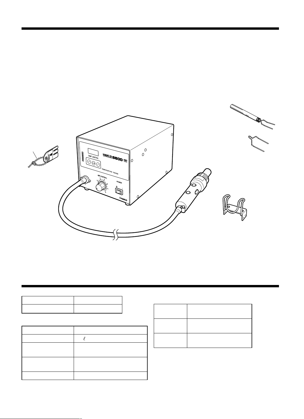
PACKING LIST
Hakko 850D station .............................................. 1
Handpiece holder .................................................1
Control card......................................................... 1
Card chain ............................................................ 1
FP pick-up ............................................................1
FP pick-up wire .................................................... 1
Instruction manual ................................................ 1
Card chain
Control
card
Hakko 850D station
* This product does not include a nozzle. A large
selection of nozzles is available for the Hakko 850D.
Select the nozzle or nozzles suitable for the work
to be performed.
FP pick-up
FP pick-up wire
SPECIFICATIONS
Name
Power consumption
● Station
Power consumption
Capacity
Control temperature
Outer dimensions
(l × w × h)
Weight (w/o cord)
Hakko 850D
120V-410W
30 W
23 /min (max.)
100 – 450°C/212 – 842°F
(sensor)
263 × 160 × 148 mm
(10.4 × 6.3 × 5.8 in.)
4.7 kg (10.36 lb.)
Handpiece
Handpiece holder
● Handpiece
Power
consumption
Total length
(w/o cord)
Weight
(w/o cord)
* This product is ESD-protected.
* Specifications and design subject to change without notice.
120V-380W
200 mm (7.9 in.)
200 g (0.44 lb.)
1
Page 3
SAFETY INSTRUCTIONS
WARNING
Warnings and cautions are placed at critical points in this manual to direct the operator's
attention to significant items. They are defined as follows:
WARNING: Failure to comply with a WARNING may result in serious injury or death.
CAUTION: Failure to comply with a CAUTION may result in injury to the operator,
or damage to the items involved. Two examples are given below.
NOTE : A NOTE indicates a procedure or point that is important to the process being describe.
EXAMPLE : AN EXAMPLE is given to demonstrate a particular procedure, point or process.
● Be sure to comply with following WARNINGS and CAUTIONS for your safety.
WARNING
● Be sure not to operate the unit with any combination of temperature and air flow settings that
makes the thermal protector trip (the heater lamp turns off during use). This could damage the unit.
CAUTION
When the power is ON, the temperature of the hot air and the nozzle ranges from 100 to 450°C
(212 to 842°F). To avoid injury to personnel or damage to items in the work area, observe the
following:
● Do not direct the hot air toward personnel or touch the metal parts near the nozzle.
● Do not use the product near combustible gases or flammable materials.
● Advise those in the work area that the unit can reach very high temperatures and should be
considered potentially dangerous.
● Turn the power OFF when no longer using the Hakko 850D or when leaving it unattended.
● Before replacing parts or storing the unit, allow the unit to cool and then turn the power OFF.
● To prevent accidents and failures, be sure to take the following precautions:
● Do not strike the handpiece against hard surfaces or otherwise subject it to physical shock.
● Be sure the unit is grounded. Always connect power to a grounded receptacle.
● Do not disassemble the pump.
● Do not modify the unit.
● Use only genuine Hakko replacement parts.
● Do not bend or damage the control card. If the card does become damaged, do not force the
card into the station slot.
● Do not wet the unit or use the unit with wet hands.
● Remove power cord by holding the plug – not the wires.
● After using, do not turn the power OFF until “P-S” is displayed on the temperature display.
● Make sure the work area is well ventilated.
● The Hakko 850D is not intended for use by children or infirm persons without supervision.
● Children should be supervised to ensure that they do not play with the Hakko 850D.
2
Page 4
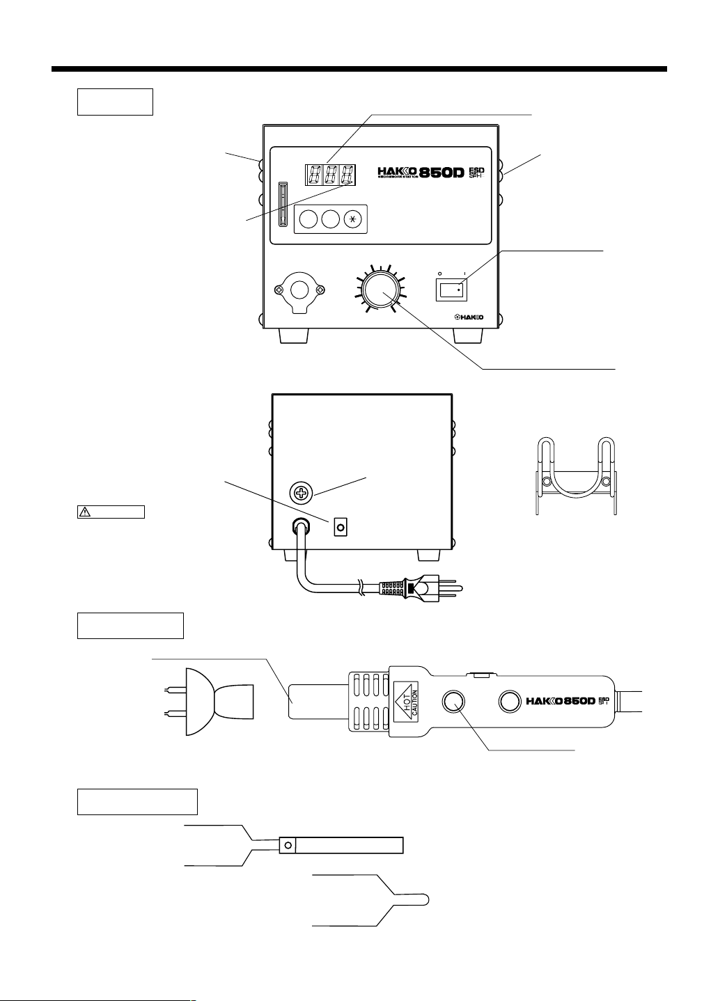
PART NAMES
Station
Handpiece holder
mounting screw
Heater
indicator lamp
Jack for optional
foot-switch
TEMP CONTROL
UP
DOWN
Temperature setting section
AIR CONTROL
4
3
2
1
TEMPERATURE RANGE 100-450°C
5
6
8
212-842°F
POWER
7
®
Airflow control knob
Fuse
Handpiece holder
mounting screw
Power switch
CAUTION
This jack is for the footswitch only. Do not
connect any other device.
Handpiece
Sensor (internal)
Nozzle (not included)
Accessories
Handpiece holder
S
Start button
FP pick-up with (S) wire
(Width of wire 14mm (0.55in.))
FP pick-up wire (L)
3
(Width of wire 30mm (1.18in.))
Page 5
PREPARATION: ASSEMBLY AND ELECTRICAL CONNECTION
Preparation: Assembly and Electrical Connection
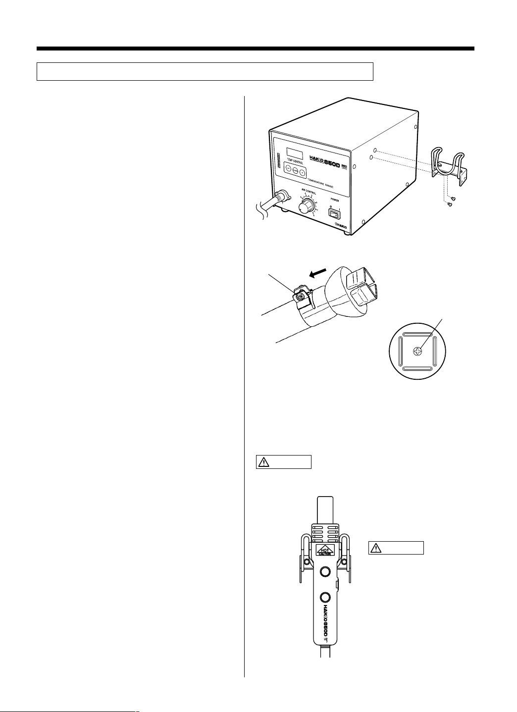
A. Station Assembly
● Attach the handpiece holder.
Remove the handpiece holder mounting screw
from the side of the station. Attach the
handpiece holder to the station. (Figure 1)
(The handpiece holder can be installed on
either the left or right side.)
(Figure 1)
Tighten the nozzle
mounting screw.
B. Handpiece Assembly
● Attach the nozzle.
Loosen the nozzle mounting screw. Attach the
nozzle as shown in the drawing.
(Figure 2)
C. Electrical Connection and
Power ON
1. Place the handpiece on the holder. (Figure
4)
2. Plug the power cord into a grounded wall
socket.
3. Turn the power switch ON.
Inside screw
(Figure 2)
(Figure 3)
When installing an optional
nozzle to the Hakko 850D, do
not remove this inside screw.
CAUTION
This product is ESD-protected. Be sure to use a grounded
wall socket.
CAUTION
S
When not in use, place the
handpiece on the holder.
(Figure 4)
4
Page 6
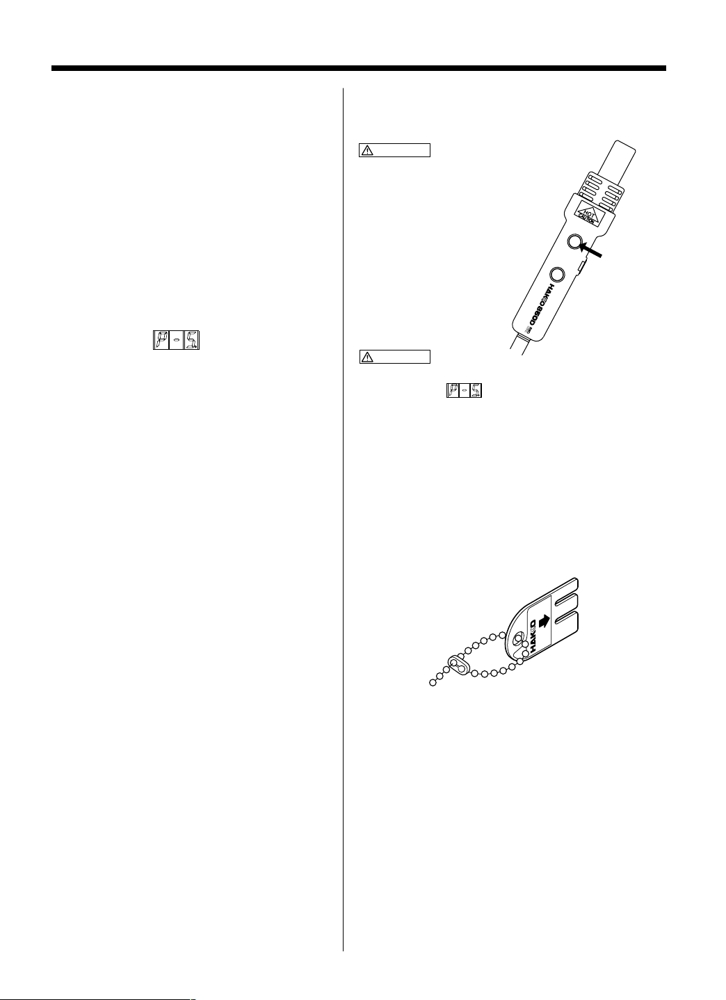
OPERATION
S
●Air Blow
1. Start
Press the Start button on the handpiece (or
the foot-switch) to start the flow of air. The
hot air blows from the tip of the nozzle, and
the temperature is controlled according to
the temperature setting.
2. Stop
Press the Start switch again. Power to the
heater is shut off and cooling begins. When
the temperature falls to 200°C (392°F), the
air stops blowing and the temperature
display reads
NOTE:
If power is turned off after use, there will be no cooldown. Automatic cool-down is only initiated by the
second activation of the Start switch.
.
CAUTION
Do not stop the hot air by turning
the power switch OFF.
CAUTION
To avoid damage to the equipment, do not turn the power
switch OFF until
appears on the display.
●Control card
Each Hakko 850D comes with a small card,
which inserts in the control slot in the front of
the unit. This card is used when entering data
for the process control functions. Any Hakko
850D card can be used with any Hakko 850D
SMD rework station.
Using the control card
The control card is used when a value is to be
changed or data are to be entered. The Hakko
850D will operate normally with the card
inserted. Remove the control card to lock the
data.
5
Page 7

Setting/Changing the Temperature
CAUTION
The temperature setting range is 100 – 450°C (212 – 842°F).
● Attempt to enter a value outside the setting range will cause the display to begin flashing the HUNDREDS digit again.
Reenter a correct value.
● Both the display temperature and the temperature setting are the temperature at the sensor. (Even with the same
temperature setting, the temperature of the hot air differs depending on the nozzle size.)
Example: Change the temperature setting from 300 to 450°C.
1. Insert the control card into the slot in the
front of the unit.
2. Press the on temperature setting
section for more than one second.
●The station goes into temperature setting
mode and the HUNDREDS digit flashes on
the display, indicating that the HUNDREDS
digit can be entered.
NOTE: It can be flashing even though no card in the
unit, but the temperature cannot be set.
3. Enter the HUNDREDS digit.
●Use the UP and
buttons to select the
DOWN
desired value for the HUNDREDS digit.
Only 1, 2, 3, or 4 can be selected. (In °F
mode, 2, 3, 4, 5, 6, 7, and 8 can be
selected). When the desired value is
displayed, press the button. The TENS
digit begins to flash.
Press and hold the button
for more than one second.
DOWN
Press the or button.
Press the button once.
UP
4. Enter TENS digit.
●Use the UP and
buttons to select the
DOWN
desired value for the TENS digit. Any value
from 0 to 9 can be selected. When the
desired value is displayed, press the
button. The UNITS digit begins to flash.
5. Enter the UNITS digit.
●Select the desired value for the UNITS digit
in the same manner as for the TENS digit.
●Press the button.
●The temperature setting is stored in
memory. Heater control begins after the
new temperature setting is displayed.
Remove the control card.
CAUTION
If the power is turned OFF before the temperature
setting procedure is completed, the new setting value
will not be stored in memory.
DOWN
Press the or button.
Press the button once.
Press the button once.
UP
6
Page 8

PARAMETERS / INITIAL RESETTING
●Entering the Parameters
°C (Celsius) or °F (Fahrenheit)
Temperature Display
The Hakko 850D has the following three parameters:
1) °C or °F temperature display selection
2) Power save time (select 30 or 60 minutes)
3) Sensor temperature display
Once the station enters parameter mode, set the
parameters in the order shown below. After all the
parameters have been set, normal operation will be
resumed.
1. Turn the power switch OFF .
2. Insert the control card into the slot in the unit.
3. Press and hold down the UP and
the temperature setting section simultaneously and
then turn the power switch ON.
3. Continue holding down both buttons until the display
shows
When the display shows
is in the parameter input mode.
●Pressing the UP or
to be displayed alternately.
F
●Press the button to select the scale. The power
save time may now be entered.
(for Celsius) or
C
DOWN
F
or
C
button will cause
buttons on
DOWN
(for Fahrenheit).
, the station
F
or
C
Power Save Time
The power save function automatically turns
off the hot air when it has blown continuously for a specified amount of time. Power to
the heater is turned off and then the air is
stopped after the handpiece cools.
Sensor Temperature Display
CAUTION
If the power is turned OFF before the parameter
setting procedure is completed, the new setting
values will not be stored in memory.
●Initial Reset
Turn the power switch ON while simultane-
ously pressing the
buttons on the temperature setting section.
The station will be reset to the following
initial values:
7
UP, DOWN
, and
●When the station enters power save time setting
mode, either
minutes or 60 minutes can be selected.
●Pressing the UP or
60
to be displayed alternately.
●Press the button to enter your selection. The
sensor temperature may now be displayed.
●No data entry is required.
The value displayed is the temperature currently
detected by the sensor.
●To end parameter input mode, press the button.
After displaying the temperature setting for two
seconds, the station returns to normal operation.
°C/°F selection
Power save time
Temperature setting
30
60
or
is displayed. Either 30
button will cause
DOWN
°C
30 minutes
300°C
30
or
Page 9

USE
● QFP Desoldering
1. Set the temperature and adjust the air
flow control knob.
Set the temperature (refer to page 6) and
adjust the air flow control knob to desired
temperature and the level.
WARNING
If the thermal protector is tripped (the heater lamp
turns off during use), reduce the temperature setting
or increase the air flow. Be sure not to operate the
unit with temperature and air flow settings that
makes the thermal protector trip. This could damage
the unit.
2. Place the FP pick-up under the IC lead.
Slip the FP pick-up wire under the IC lead.
(Refer to the photo shown.)
If the width of the IC does not match the size
of the FP pick-up, adjust the width of the
pick-up by squeezing the wire. In case of
PLCC or small components such as chip
resistors, desolder by using tweezers, etc.
TEMP CONTROL
UP
DOWN
AIR CONTROL
3
2
1
4
TEMPERATURE RANGE 100-450°C
5
8
212-842°F
POWER
6
7
®
Airflow control knob
3. Heating
Hold the handpiece so that the nozzle is
located directly over, but not touching the IC,
and allow the hot air to melt the solder. Be
careful not to touch the leads of the IC with
the nozzle.
4. Remove the IC.
Once the solder has melted, remove the IC
by lifting the FP pick-up.
5. Remove any remaining solder.
After removing the IC, remove remaining
solder with a soldering iron and wick or
desoldering tool.
8
Page 10

USE
● QFP Soldering
1. Apply the solder paste.
Apply the proper quantity of solder paste
and install the SMD on the PWB.
2. Preheat the SMD.
Preheat the SMD as shown in the photo.
3. Soldering
Heat the lead frame evenly.
4. Cleaning
When soldering is completed, clean the
residual flux from the board with an
appropriate cleaner.
NOTE:
Soldering with hot air has many advantages, such
as the inherent ability to pre-heat the component
being replaced. As with any soldering process,
however, there is always the possibility of forming
solder balls, bridges between leads, and inadequate
solder joints. Always inspect the finished solder
joints for structural and electrical integrity.
9
Page 11

MAINTENANCE / INSPECTION
●Broken Heater or Sensor
(1) Open the handpiece.
1. Remove the three screws holding the
handpiece together.
2. Move the tube downward.
3. Remove the pipe from the protruding
portion of the handle.
CAUTION
Quartz glass and heat insulation are inside the pipe.
Be careful not to drop or lose these items.
4. Disconnect the heater sensor connector
and remove the heater.
(2) Measure the resistance value.
1. Measure the resistance value (a) of the
sensor. The correct value is 0 Ω.
2. Measure the resistance value (b) of the
heater. The correct values are approximately 33 Ω (±10%) (100-120 V), 85 Ω
(±10%) (220-240 V) at room temperature.
If the resistance value is incorrect, replace the
part.
(Refer to the instructions included with the
replacement part.)
Heater connector
Sensor connector
a
b
10
Page 12

ERROR MESSAGES
When the error detection software in the Hakko 850D detects an error, a message is
displayed to alert the operator. See “Troubleshooting” for procedures to correct the error.
Sensor Error
Heater Error
This error occurs when there is the possibility of a
sensor failure (or a failure in the sensor circuit).
flashes and the power is shut down.
This error occurs when the temperature of the hot air
is falling even though the heater is on. flashes
to indicate the possibility of a heater failure.
11
Page 13

TROUBLESHOOTING
WARNING
● Before checking the inside of the Hakko 850D or replacing parts, be sure to
disconnect the power plug. Failure to do so may result in electric shock.
● The unit does not operate
when the power switch is
turned ON.
● flashes, indicating a
sensor error.
● flashes, indicating a
heater error.
CHECK
ACTION
CHECK
ACTION
CHECK
ACTION
: Is the fuse blown?
: Investigate why the fuse blew and then
replace the fuse. If the cause can not be
determined, replace the fuse. If the fuse
blows again, send the unit in for repair.
: Is the sensor broken?
: See the procedure for checking a potentially
broken sensor.
: Is the heater broken?
: See the procedure for checking a potentially
broken heater.
12
Page 14

OPTIONAL NOZZLE
NOTE
The size in Name/Specification
indicates the size of IC package.
QFP SOP
PLCC SOJ
A
B
C
Air flow
D
No.
C 0.8 (0.03)
D 1.8 (0.07)
Except for
A1189B,
A1191,
A1192
C 1.0 (0.04)
D 1.8 (0.07)
A1189B
C 1.0 (0.04)
D 2.0 (0.08)
A1191
mm (inch)
C 0.8 (0.03)
D 2.0 (0.08)
A1192
A1124B Single ø2.5
(0.09)
ø2.5 (I.D.)
(0.09)
A1129B QFP 28 x 28
(1.1 x 1.1)
29
(1.14)
A:29.7 (1.17)
29 (1.14)
B:29.7 (1.17)
A1134 SOP 7.5 x 18
(0.3 x 0.7)
19
(0.75)
7.2 (0.28)
A1139B PLCC 12.5 x 7.3
(0.49 x 0.29)
(18 Pins)
A1125B QFP 10 x 10
(0.39 x 0.39)
10
(0.39)
A:10.2 (0.4)
B:10.2 (0.4)
10
(0.39)
A1130 Single ø4.4
(0.17)
ø4.4 (I.D.)
(0.17)
A1135B PLCC 17.5 x 17.5
(0.68 x 0.68)
(44 Pins)
15
(0.59)
A:18.5 (0.73)
B:18.5 (0.73)
15 (0.59)
A1140B PLCC 11.5 x 11.5
(0.45 x 0.45)
(28 Pins)
A1126B QFP 14 x 14
(0.55 x 0.55)
15
(0.59)
A:15.2 (0.6)
B:15.2 (0.6)
15
(0.59)
A1131 SOP 4.4 x 10
(0.17 x 0.39)
10
(0.39)
4.8
(0.19)
A1136B PLCC 20 x 20
(0.78 x 0.78)
(52 Pins)
A:21 (0.83)
19 (0.75)
B:21 (0.83)
A1141B PLCC 11.5 x 14
(0.45 x 0.55)
(32 Pins)
A1127B QFP 17.5 x 17.5
(0.68 x 0.68)
A:19.2 (0.76)
B:19.2 (0.76)
19
(0.75)
A1132 SOP 5.6 x 13
(0.22 x 0.51)
5.7
(0.22)
A1137B PLCC 25 x 25
(0.98 x 0.98)
(68 Pins)
19
(0.75)
A:26 (1.02)
24 (0.94)
B:26 (1.02)
A1142B Bent Single
1.5 x 3 (0.06 x 0.12)
A1128B QFP 14 x 20
(0.55 x 0.78)
19
(0.75)
A1133 SOP 7.5 x 15
(0.3 x 0.59)
15
(0.59)
A1138B PLCC 30 x 30
(1.18 x 1.18)
(84 Pins)
24
(0.94)
A1180B BQFP 17 x 17
(0.67 x 0.67)
21
(0.83)
7.2
(0.28)
29 (1.14)
15
(0.59)
A:15.2 (0.6)
B:21.2 (0.83)
16
(0.63)
A:31 (1.22)
B:31 (1.22)
29
(1.14)
6.9
(0.27)
A1181B BQFP 19 x 19
(0.75 x 0.75)
16
(0.63)
13
A: 9 (0.35)
B:14 (0.55)
16
(0.63)
A:19.2 (0.76)
B:19.2 (0.76)
6.9
(0.27)
10 (0.39)
A1182B BQFP 24 x 24
(0.94 x 0.94)
21 (0.83)
10
A:13 (0.51)
B:13 (0.51)
21
(0.83)
A:24.2 (0.95)
B:24.2 (0.95)
(0.39)
With screws
10 (0.39)
A1183 SOJ 15 x 8
(0.59 x 0.31)
8
(0.31)
A:15 (0.59)
B:13 (0.51)
16
(0.63)
15
(0.59)
A1184B SOJ 18 x 8
(0.71 x 0.31)
45°
10 (0.39)
1.5
(0.06) (I.D.)
3 (0.12) (I.D.)
19
(0.75)
13.6
(0.54)
A:18.2 (0.72)
B:18.2 (0.72)
13.6
(0.54)
A1185B TSOL 13 x 10
(0.51 x 0.39)
10
11.9
(0.47)
(0.39)
Page 15

A1186B TSOL 18 x 10
(0.71 x 0.39)
18.2 (0.72)
A1187B TSOL 18.5 x 8
(0.73 x 0.31)
11.7
(0.46)
18.5 (0.73)
A1188B PLCC 9 x 9
(0.35 x 0.35)
(20 Pins)
10
(0.39)
10
(0.39)
10
(0.39)
A:11 (0.43)
B:11 (0.43)
A1189B PLCC 34 x 34
(1.34 x 1.34)
(100 Pins)
33.5 (1.32)
A:36.5 (1.44)
33.5 (1.32)
B:36.5 (1.44)
A1190 Dual Single
2.5 x 9.5
Pitch (0.09 x 0.37)
ø2.5 (I.D)
(0.09)
A1191 SIP 25L (0.98)
26 (1.02)
A1257B SOP 11 x 21
(0.43 x 0.83)
11.7 (0.46)
A1262B QFP 12 x 12
(0.47 x 0.47)
12
(0.47)
A:12.2 (0.48)
12 (0.47)
B:12.2 (0.48)
A1325 Dual Single
ø1.5 x 5-10
(0.06 x 0.2-0.39)
Adjustable Pitch
A1192 SIP 50L (1.97)
2 (0.08)
A1258B SOP 7.6 x 12.7
(0.3 x 0.5)
21
(0.83)
A1263B QFP 28 x 40
(1.1 x 1.57)
52.5 (2.07)
8.2 (0.32)
39 (1.54)
2 (0.08)
11.7
(0.46)
29
(1.14)
A:27.7 (1.09)
B:39.7 (1.56)
5 (0.2)
A1203B QFP 35 x 35
(1.38 x 1.38)
A:35.2 (1.39)
30.6 (1.20)
A1259B SOP 13 x 28
(0.51 x 1.1)
B:35.2 (1.39)
13.5 (0.53)
A1264B QFP 40 x 40
(1.57 x 1.57)
A:40.2 (1.58)
39 (1.54)
10 (0.39)
B:40.2 (1.58)
A1214B SOJ 10 x 26
(0.39 x 1.02)
30.6 (1.20)
A1260B SOP 8.6 x 18
(0.34 x 0.71)
29
(1.14)
A1265B QFP 32 x 32
(1.26 x 1.26)
39
(1.54)
12 (0.47)
8.7 (0.34)
31
(1.22)
25.9 (1.02)
19
(0.75)
31
(1.22)
A:32.2 (1.27)
B:32.2 (1.27)
A1215B QFP 42.5 x 42.5
(1.67 x 1.67)
40 (1.57)
A:42.5 (1.67)
40 (1.57)
B:42.5 (1.67)
A1261B QFP 20 x 20
(0.78 x 0.78)
21
(0.83)
A:20.2 (0.8)
B:20.2 (0.8)
21 (0.83)
5 (0.2)
The pitch
between the
two nozzles
is adjustable.
10 (0.39)
ø1.5 (I.D.)
(0.06)
Screw
14
Page 16

PARTS LIST / STATION
*Spare or repair parts do not include mounting screws, if they are not
listed on the description. Screws must be ordered separately.
Item No.
1
2
3
4
5
6
7
8
9
Part No.
B2732
B2462
B2463
B2317
B1084
B1028
B2388
B2730
B2047
Part Name
P.W.B./display
P.W.B./heat control
Radiation sheet
Insulation sheet
Switch
Knob
Control card
Chassis
Membrane sheet
1
Pan head screw
with washer
(w/Spring washer)
(M3 x 6) (5)
Description
100-120 V With triac
With screw
With display window,
membrane sheet,
rubber foot
2
Pan head screw
with washer
(w/Spring washer)
(M3 x 6) (4)
7
9
6
21
Hexagonal socket
set screw
(M3 x 3)
Pan head screw
with washer
(w/Spring, Plain washer)
(M3 x 8)
3
8
16
14
15
Truss screw
(Zn · black)
(M4 x 5) (16)
Pan head screw
with washer
(w/Spring washer)
17
(M4 x 10) (4)
18
Pan head screw
with washer
4
(w/Spring washer)
(M4 x 6)
External tooth
lock washer
(nominal size 4)
11
12
13
Pan head screw
A
I
R
C
O
N
T
R
O
L
with washer
(w/Spring, Plain washer)
(M3 x 6) (2)
Part No.
Item No.
*If you need item no. 21. Exhaust nozzle, contact your
Hakko representative.
B2733
10
B1041
11
B1257
12
B1319
13
B2731
14
B2480
15
B2472
16
B2473
17
B2477
18
B2734
19
B1204
20
Part Name
Transformer
Description
120 V
Fuse holder
Fuse 250V-5A (U)
100-120 V
Power cord, 3 core & American plug
Cover
Air pump
110-120 V, With high nut,
nylon band, double-side tape
Sound-proof tank
Silicone tube
8 x 5 x 130 mm
(0.3 x 0.2 x 5.1 in.)
Handpiece holder
Tube connector
Rubber foot
With silicone tube assembly
4 ea.
10
Option
External tooth
lock washer
(nominal size 3)
5
Plain washer
polycarbonate
(nominal size 5) (4)
20
19
Option
Item No.1Part No.
B1649
1
Part Name
Foot switch
Footswitch
(sold separately)
Description
15
Truss screw
(M4 x 18) (4)
16
Page 17

PARTS LIST / HANDPIECE
*Spare or repair parts do
not include mounting
screws, if they are not
listed on the description.
Screws must be ordered
separately.
5
4
1
2
6
Item No.
1
2
3
4
5
6
7
8
9
10
Part No.
B2452
A1434
B2735
B2456
B2457
B2458
B1354
B2736
B2635
B2634
Part Name
Pipe
Heating element
Handle
Packing
Terminal board
Fixing for terminal
Cord stopper
Cord asse’y
Clamp
Protective spring
Description
With glass pipe, mica
100-120 V
With screws, buttons, knob
With screws
120 V
With silicone hose,
protective spring
120 V only
120 V only with nylon strap
Tapping screw
(Fluted point)
(M2.6 x 6) (3)
9
7
8
Pan head screw
(Zn · black)
(M3 x 10) (2)
Tapping screw
(M2.6 x 10) (2)
10
3
Tapping screw
(M3 x 12) (3)
17
Page 18

WIRING DIAGRAM
Pump
Fuse
Power cord
Power switch
2
1
P.W.B./Triac
P.W.B./Display
1
CN3
12
CN4
1
Transformer
11
1
CN4
2
1
CN3
3
AC15V
CN7
12
1111
CN6
P.W.B./Heat control
CN1
CN5
241
1
Jack for foot switch
Handpiece
Terminal board
SW2
GRAY
BLUE
WHITE
1
313
CN9CN8
1
CN10
3
1
CN2
2
VACUUM
1
1
GND
1
SW1
START
-
CA sensor
+
Heater
Heater element
18
Page 19

HEAD OFFICE
4-5, SHIOKUSA 2-CHOME, NANIWA-KU, OSAKA, 556-0024 JAPAN
TEL:+81-6-6561-3225 FAX:+81-6-6561-8466
http://www.hakko.com/
AMERICAN HAKKO PRODUCTS, INC.
28920 N. AVENUE WILLIAMS VALENCIA CA 91355, U.S.A.
TEL: (661) 294-0090 FAX: (661) 294-0096
Toll Free (800)88-HAKKO
4 2 5 5 6
http://www.hakkousa.com/
19
MA01081JU011107
Nov. 2001
 Loading...