

Page 1
®
SMD Rework Station
●
Thank you for purchasing the Hakko 850B SMD Rework
Station.
The Hakko 850B is designed to solder and desolder surface
mounted devices with hot air.
Please read this manual before operating the Hakko 850B.
Keep this manual readily accessible for reference.
●
TABLE OF CONTENTS
PACKING LIST / SPECIFICATIONS....................................................... 1
SAFETY INSTRUCTIONS...................................................................... 2
PART NAMES......................................................................................... 3
PREPARATION: ASSEMBLY AND ELECTRICAL CONNECTION......... 4
OPERATION........................................................................................... 5
MAINTENANCE / INSPECTION ............................................................ 7
TEMPERATURE DISTRIBUTION CHART ............................................. 8
OPTIONAL NOZZLES.......................................................................... 11
PARTS LIST / HANDPIECE................................................................. 12
STATION ....................................................................... 13
WIRING DIAGRAM .............................................................................. 15
Page 2
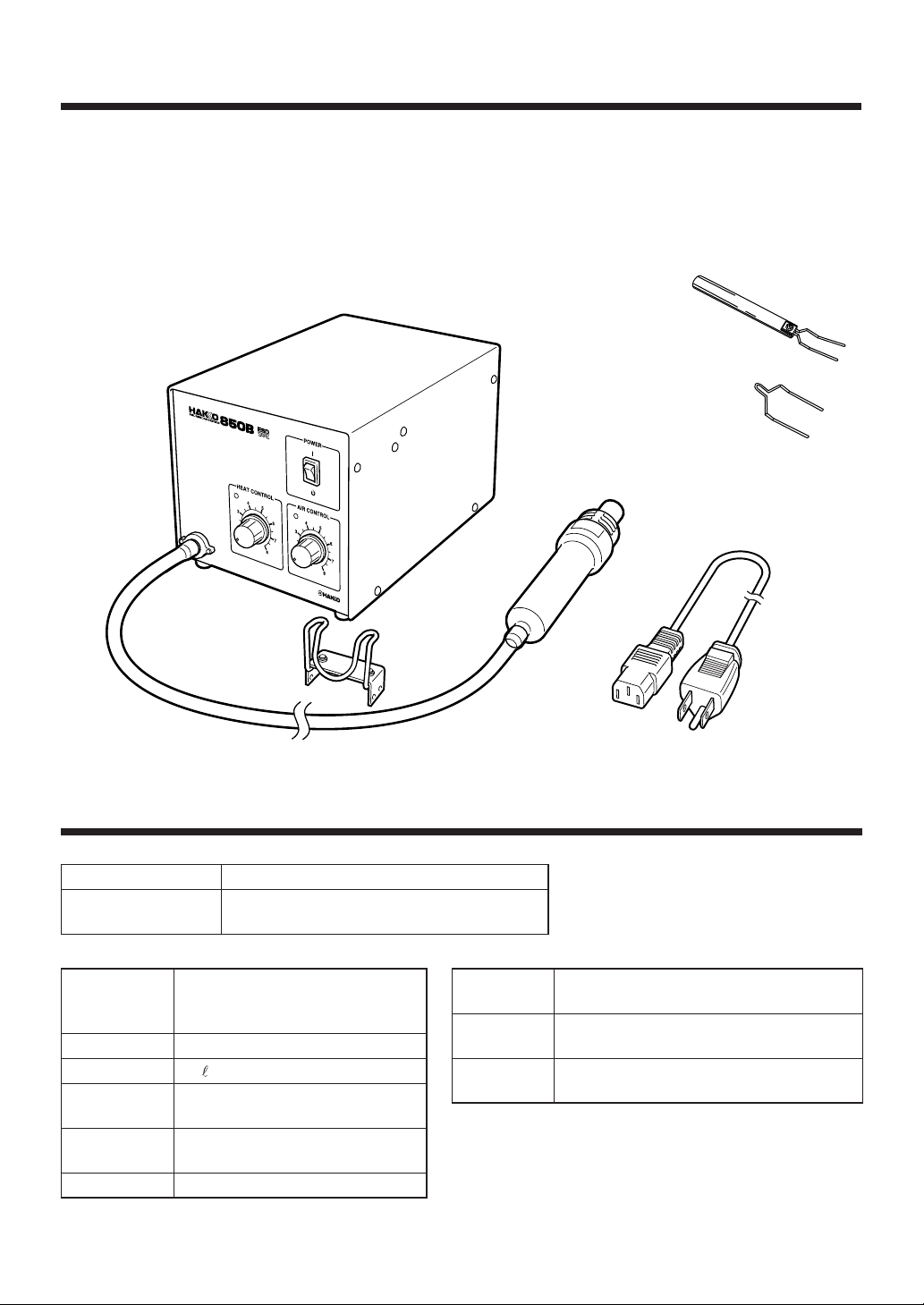
PACKING LIST
Check the contents of the Hakko 850B package and
confirm that all the items listed below are included:
Hakko 850B station ............................................. 1
Po wer cord .......................................................... 1
Handpiece holder ................................................ 1
FP pick-up ........................................................... 1
FP pick-up wire.................................................... 1
Instruction manual ............................................... 1
Hakko 850B station
Handpiece holder
* This product does not include a nozzle. A large
selection of nozzles is available for the Hakko
850B. Select the nozzle or nozzles suitab le for the
work to be performed.
FP pick-up
with (S) wire
FP pick-up wire (L)
Handpiece
Power cord
SPECIFICATIONS
Name
Power consumption
● Station
Power
Consumption
Pump
Capacity
Control
temperature
External
dimensions
Weight
1
Hakko 850B
100V – 280W 110V – 270W 120V – 300W
220V – 300W 230V – 310W 240V – 310W
30 W
(Stand-by power consumption
100 – 120V 2W, 220 – 240V 4W)
Diaphragm pump
/min (max)
23
100˚– 420˚C (212˚– 788˚F)
(Use A1126B)
225(l) × 160(w) × 145(h) mm.
8.9(l) × 6.3(w) × 5.7(h) in.
4 kg. (8.82 lb.)
● Handpiece
Power
consumption
Total length
(w/o cord)
Weight
(w/o cord)
* This product is ESD-protected.
* Specifications and design subject to change without notice.
100V – 250W 110V – 240W 120V – 270W
220V – 270W 230V – 280W 240V – 280W
196(l) mm / 7.72(l) in.
120 g / 0.26 lb.
Page 3
SAFETY INSTRUCTIONS
W ARNING
Warnings and cautions are placed at critical points in this manual to direct the operator's attention
to significant items. They are defined as follows:
W ARNING: Failure to comply with a WARNING may result in serious injury or death.
CAUTION: Failure to comply with a CA UTION ma y result in injury to the operator , or
damage to the items involved. Two examples are giv en below.
●●
● Be sure to comply with following WARNINGS and CAUTIONS for your safety.
●●
W ARNING
● Be sure not to operate the unit with any combination of temperature and air flow settings that
makes the thermal protector trip (the heater lamp turns off during use). This could damage the
unit.
● After use, do not disconnect the plug during the automatic cool-down process.
CAUTION
When the power is ON, the temperature of the hot air and the nozzle ranges from 100° to
450°C. (212° to 842°F.). To avoid injury to personnel or damage to items in the work area,
observe the following:
● Do not direct the hot air toward personnel or touch the metal parts near the nozzle.
● Do not use the product near combustible gases or flammab le materials.
● Advise those in the work area that the unit can reach very high temperatures and should be
considered potentially dangerous.
● Turn the power OFF when no longer using the Hakko 850B or when leaving it unattended.
● Before replacing parts or storing the unit, allow the unit to cool and then turn the power OFF.
●●
● To prevent accidents and failures, be sure to take the following precautions:
●●
● Do not strike the handpiece against hard surfaces or otherwise subject it to physical shoc k. This
will damage the quartz glass shield around the heating element, and could damage the heater
as well.
● Be sure the unit is grounded. Alw ays connect power to a grounded receptacle.
● Do not disassemble the pump.
● Do not modify the unit.
● Use only genuine Hakko replacement parts.
● Do not wet the unit or use the unit with wet hands.
● Remove po wer cord by holding the plug - not the wires.
● Make sure the work area is well ventilated.
● The Hakko 850B is not intended for use by children or infirm persons without supervision.
● Children should be supervised to ensure that they do not play with the Hakko 850B.
2
Page 4
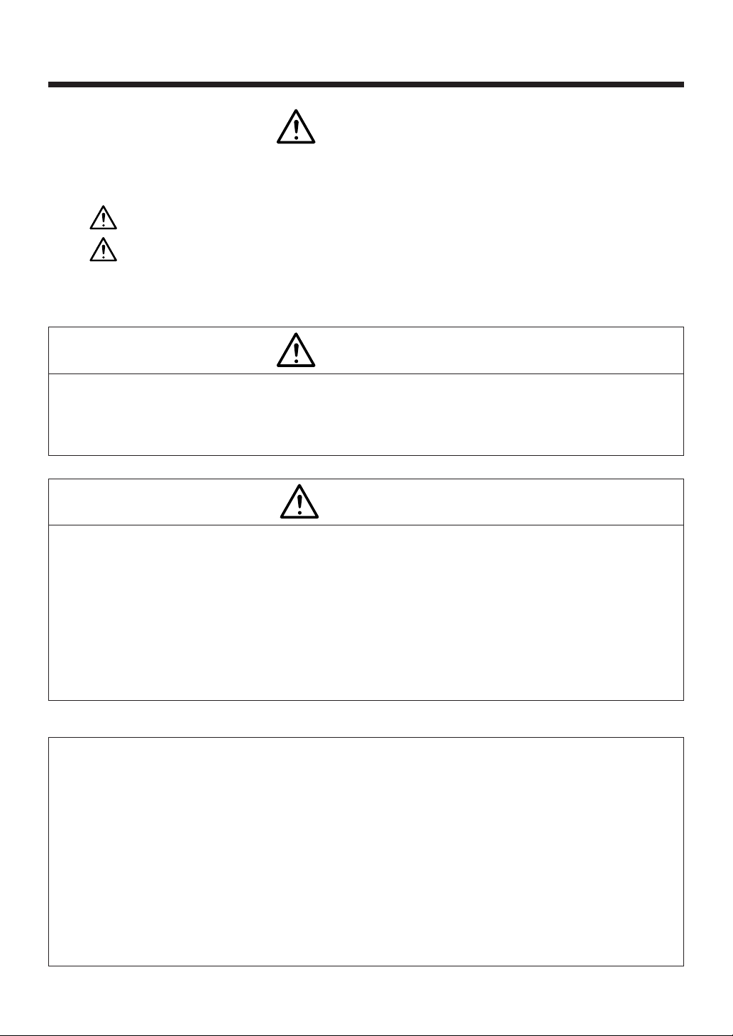
PART NAMES
Station
Handpiece holder
mounting screw
Air flow lamp
Heater lamp
Power
receptacle
HEAT CONTROL
4
3
2
1
POWER
AIR CONTROL
4
5
6
7
8
5
3
2
6
7
1
8
Handpiece holder
mounting screw
Power switch
Air flow
control knob
Temperature
control knob
Handpiece holder
Handpiece
Accessories
Fuse
Nozzle (not included)
FP pick-up with (S) wire
(Width of wire 14mm (0.55in.))
FP pick-up wire (L)
(Width of wire 30mm (1.18in.))
HOT
CAUTION
3
3
Page 5
PREPARATION: ASSEMBLY AND ELECTRICAL CONNECTION
Preparation: Assembly and Electrical Connection
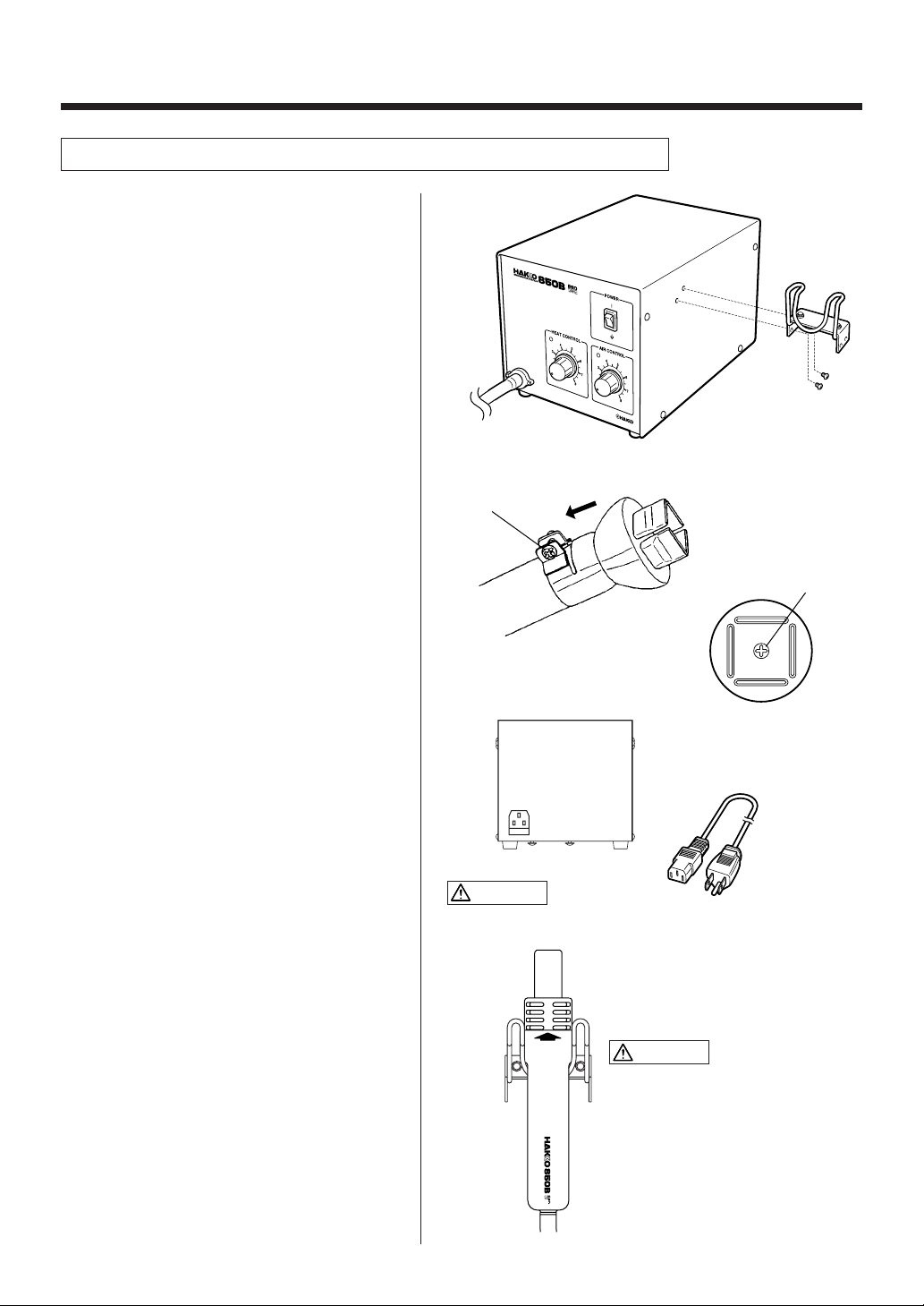
A. Station Assembly
●●
● Attach the handpiece holder.
●●
Remove the handpiece holder mounting
screw from the side of the station. Attach the
handpiece holder to the station. (Figure 1)
(The handpiece holder can be installed on
either the left or right side.)
(Figure 1)
B. Handpiece Assembly
●●
● Attach the nozzle.
●●
Loosen the nozzle mounting screw. Attach
the nozzle as shown in the drawing.
(Figure 2)
C. Electrical Connection and
Power ON
1. Connect the power cord to the power
receptacle on the back panel of the
station. (Figure 4)
2. Place the handpiece on the holder.
(Figure 5)
3. Plug the power cord into a grounded wall
socket. After connection, the automatic
blowing function will start sending air
through the pipe, but the heating element
remains cool.
4. T urn the pow er switch ON.
NOTE: The power switch may be turned on at
any time while the automatic blowing
function is operating. Once the power
switch is turned on, the heating element
will begin to warm up.
Tighten the nozzle
mounting screw.
Inside screw
(Figure 2)
(Figure 3)
When installing an optional
nozzle to the Hakko 850B, do
not remove this inside screw.
(Figure 4)
CAUTION
This product is ESD-protected. Be sure to use a g rounded wall
socket.
HOT
CAUTION
CAUTION
When not in use, place the handpiece
on the holder.
T op View
(Figure 5)
4
Page 6

OPERATION
●●
● QFP Desoldering
●●
1. Adjust the air flow and temperature
control knobs.
Refer to the temperature distribution chart
(page 8) to adjust the air flow and temperature control knobs. Wait for the temperature to stabilize for a short period of time.
HEAT CONTROL
4
3
2
1
POWER
AIR CONTROL
4
5
6
7
8
5
3
6
2
7
1
8
Air flow control knob
WARNING
If the thermal protector is tripped (the heater
lamp turns off during use), reduce the temperature setting or increase the air flow . Be sure
not to operate the unit with temperature and air
flow settings that makes the thermal protector
trip. This could damage the unit.
2. Place the FP pick-up under the IC lead.
Slip the FP pick-up wire under the IC lead.
(Refer to the photo shown.)
If the width of the IC does not match the
size of the FP pick-up , adjust the width of
the pick-up by squeezing the wire. In case
of PLCC or small components such as
chip resistors, desolder by using
tweezers, etc.
3. Heating
Hold the handpiece so that the nozzle is
located directly over , but not touching the
IC, and allow the hot air to melt the solder .
Be careful not to touch the leads of the IC
with the nozzle.
Temperature control knob
4. Remove the IC.
Once the solder has melted, remove the
IC by lifting the FP pick-up.
5. Remove any remaining solder.
After removing the IC, remov e remaining
solder with a soldering iron and wick or
desoldering tool.
5
Page 7

OPERATION
●●
● QFP Soldering
●●
1. Apply the solder paste.
Apply the proper quality of solder paste
and install the SMD on the PWB.
2. Preheat the SMD.
Refer to the photo to preheat SMD.
3. Soldering
Heat the lead frame ev enly.
4. Cleaning
When soldering is completed, clean the
residual flux from the board with an
appropriate cleaner.
NOTE:
Soldering with hot air has many advantages,
such as the inherent ability to pre-heat the
component being replaced. As with any
soldering process, however, there is always the
possibility of forming solder balls, bridges
between leads, and inadequate solder joints.
Always inspect the finished solder joints for
structural and electrical integrity.
●●
● Turn the power switch off.
●●
After the power switch is turned off, an
automatic blowing function begins sending
cool air through the pipe in order to cool the
handpiece. Do not disconnect the plug
during this cooling process.
CAUTION
During the cooling process, the amount of air is
controlled by the setting of the air flow adjustment
knbob. Hakko recommends setting the knob at 8
when cooling for greatest efficiency.
6
Page 8

MAINTENANCE / INSPECTION
●●
● Broken heating element
●●
A. Open the handpiece
1. Remove the three screws holding the
handpiece together. (Figure 1)
2. Move the tube away from the handpiece,
as shown.
3. Open the handpiece. Disconnect the
grounding wire sleeve (1) and pipe from
the protruding portion of the handle.
Remove the pipe.
CAUTION
Quartz glass and heat insulation are inside the
pipe. Be careful not to drop or lose these items.
(Figure 1)
Connector (2)
4. Disconnect the connector (2) and remove
the heating element.
B. Measure the resistance
value
Connect an ohmmeter across the connector
terminals (a). The correct values are approximately:
26-40Ω (100-120V), 70-100Ω (220-240V).
If the resistance value is incorrect, replace
the part.
(Refer to the instructions included with the
replacement part.)
CAUTION
Handle the heating element with care.
the heating element wire!
Insert the handle's projection into the hole in the
pipe.
●●
● Replacing the fuse
●●
Never rub
Grounding wire
sleeve (1)
(a)
1. Unplug the power cord from the power
receptacle.
2. Remove the fuse holder.
3. Replace the fuse.
5A (100-120V), 3.15A (220-240V)
4. Put the fuse holder back in place.
7
Page 9

TEMPERATURE DISTRIBUTION CHART
CAUTION These charts are for reference. If the thermal protector trips, reduce the temperature setting
or increase the air flow.
Test criteria: Measured at a point 3mm (0.12 in.) from the nozzle by recorder.
A1124B
Single Ø2.5 (0.09)
Air Temperature
˚C
500
(932˚F)
300
(572˚F)
100
(212˚F)
15842736
Temperature Control Knob
A1127B
Air Temperature
˚C
QFP 17.5×17.5 (0.68×0.68)
500
(932˚F)
300
(572˚F)
100
(212˚F)
15842736
Temperature Control Knob
A1125B
QFP 10×10 (0.39×0.39)
Air flow
68
4
2
1
Air flow
4
2
6
8
Air Temperature
˚C
500
(932˚F)
300
(572˚F)
100
(212˚F)
A1128B
Air Temperature
˚C
QFP 14×20 (0.55×0.78)
500
(932˚F)
300
(572˚F)
100
(212˚F)
Air flow
2
46
15842736
Temperature Control Knob
Air flow
15842736
Temperature Control Knob
4
2
8
6
8
A1126B
QFP 14×14 (0.55×0.55)
Air Temperature
˚C
500
(932˚F)
300
(572˚F)
100
(212˚F)
15842736
Temperature Control Knob
A1129B
Air Temperature
˚C
QFP 28×28 (1.1×1.1)
500
(932˚F)
300
(572˚F)
100
(212˚F)
15842736
Temperature Control Knob
Air flow
2
Air flow
2
4
6
8
4
6
8
A1130
Air Temperature
˚C
Air Temperature
˚C
Single Ø4.4 (0.17)
500
(932˚F)
300
(572˚F)
100
(212˚F)
15842736
Temperature Control Knob
A1133
SOP 7.5×15 (0.3×0.59)
500
(932˚F)
300
(572˚F)
100
(212˚F)
15842736
Temperature Control Knob
1
Air flow
2
Air flow
4
6
4
2
A1131
SOP 4.4×10 (0.17×0.39)
8
6
8
Air Temperature
˚C
500
(932˚F)
300
(572˚F)
100
(212˚F)
Air Temperature
˚C
500
(932˚F)
300
(572˚F)
100
(212˚F)
Air flow
2
4
15842736
Temperature Control Knob
A1134
SOP 7.5×18 (0.3×0.7)
Air flow
15842736
Temperature Control Knob
4
2
6
8
6
8
A1132
SOP 5.6×13 (0.22×0.51)
Air Temperature
˚C
500
(932˚F)
300
(572˚F)
100
(212˚F)
15842736
Temperature Control Knob
A1135B
PLCC 17.5×17.5 (0.68×0.68)
(44 Pins)
Air Temperature
˚C
500
(932˚F)
300
(572˚F)
100
(212˚F)
15842736
Temperature Control Knob
Air flow
2
2
46
Air flow
8
4
6
8
8
Page 10

TEMPERATURE DISTRIBUTION CHART
A1136B
PLCC 20×20 (0.78×0.78)
(52 Pins)
Air Temperature
˚C
500
(932˚F)
300
(572˚F)
100
(212˚F)
15842736
Temperature Control Knob
A1139B
PLCC 12.5×7.3 (0.49×0.29)
500
(932˚F)
300
(572˚F)
100
(212˚F)
(18 Pins)
15842736
Temperature Control Knob
Air Temperature
˚C
Air flow
2
Air flow
2
A1137B
PLCC 25×25 (0.98×0.98)
4
6
8
4
6
8
Air Temperature
˚C
Air Temperature
˚C
(68 Pins)
500
(932˚F)
300
(572˚F)
100
(212˚F)
15842736
Temperature Control Knob
A1140B
PLCC 11.5×11.5 (0.45×0.45)
(28 Pins)
500
(932˚F)
300
(572˚F)
100
(212˚F)
15842736
Temperature Control Knob
Air flow
2
2
4
Air flow
6
8
4
6
8
A1138B
PLCC 30×30 (1.18×1.18)
(84 Pins)
Air Temperature
˚C
500
(932˚F)
300
(572˚F)
100
(212˚F)
15842736
Temperature Control Knob
A1141B
PLCC 11.5×14 (0.45×0.55)
(32 Pins)
Air Temperature
˚C
500
(932˚F)
300
(572˚F)
100
(212˚F)
15842736
Temperature Control Knob
Air flow
2
Air flow
2
4
6
8
4
6
8
A1142B
Bent Single 1.5×3 (0.06×0.12)
Air Temperature
˚C
500
(932˚F)
300
(572˚F)
100
(212˚F)
Air Temperature
˚C
500
(932˚F)
300
(572˚F)
100
(212˚F)
1
15842736
Temperature Control Knob
A1257B
SOP 11×21 (0.43×0.83)
15842736
Temperature Control Knob
2
Air flow
A1182B
Air flow
8
4
6
4
2
6
8
Air Temperature
˚C
Air Temperature
˚C
(932˚F)
(572˚F)
(212˚F)
BQFP 24×24 (0.94×0.94)
500
(932˚F)
300
(572˚F)
100
(212˚F)
15842736
Temperature Control Knob
A1258B
SOP 7.6×12.7 (0.3×0.5)
500
300
100
15842736
Temperature Control Knob
Air flow
2
24
Air flow
6
4
6
8
8
A1187B
TSOL 18.5×8 (0.73×0.31)
Air Temperature
˚C
500
(932˚F)
300
(572˚F)
100
(212˚F)
15842736
Temperature Control Knob
A1259B
SOP 13×28 (0.51×1.1)
Air Temperature
˚C
500
(932˚F)
300
(572˚F)
100
(212˚F)
15842736
Temperature Control Knob
Air flow
24
Air flow
2
6
8
4
6
8
9
Page 11

A1260B
SOP 8.6×18 (0.34×0.71)
Air Temperature
˚C
500
(932˚F)
300
(572˚F)
Air flow
24
A1261B
QFP 20×20 (0.78×0.78)
6
8
Air Temperature
˚C
500
(932˚F)
300
(572˚F)
2
Air flow
4
6
8
Air Temperature
˚C
A1262B
QFP 12×12 (0.47×0.47)
500
(932˚F)
300
(572˚F)
Air flow
2
4
6
8
100
(212˚F)
15842736
Temperature Control Knob
A1263B
Air Temperature
˚C
Air Temperature
˚C
QFP 28×40 (1.1×1.57)
500
(932˚F)
300
(572˚F)
100
(212˚F)
15842736
Temperature Control Knob
A1325
Dual Single Ø1.5×5-10
(0.06×0.2-0.39)
500
(932˚F)
300
(572˚F)
100
(212˚F)
15842736
Temperature Control Knob
A1264B
Air flow
4
Air flow
6
8
6
8
2
4
2
Air Temperature
˚C
QFP 40×40 (1.57×1.57)
500
(932˚F)
300
(572˚F)
100
(212˚F)
15842736
Temperature Control Knob
2
Air flow
4
6
8
100
(212˚F)
15842736
Temperature Control Knob
A1265B
QFP 32×32 (1.26×1.26)
Air Temperature
˚C
500
(932˚F)
300
(572˚F)
100
(212˚F)
15842736
Temperature Control Knob
2
Air flow
4
6
8
100
(212˚F)
15842736
Temperature Control Knob
10
Page 12

OPTIONAL NOZZLES
NOTE:
The size in Name/
Specification
indicates the size
of IC package.
A1124B Single Ø2.5
(0.09)
Ø2.5 (I.D.)
(0.09)
A1129B QFP 28×28
(1.1×1.1)
A:29.7 (1.17)
6.9
(0.27)
B:29.7 (1.17)
A: 9 (0.35)
B:14 (0.55)
29 (1.14)
A1134 SOP 7.5×18
(0.3×0.7)
7.2 (0.28)
A1139B PLCC 12.5×7.3
(0.49×0.29)
(18 Pins)
A1187B TSOL 18.5×8
(0.73×0.31)
QFP SOP
A1125B QFP 10×10
(0.39×0.39)
A1130 Single Ø4.4
(0.17)
29
(1.14)
Ø4.4 (I.D.)
(0.17)
A1135B PLCC 17.5×17.5
(0.68×0.68)
(44 Pins)
19
(0.75)
15 (0.59)
A1140B PLCC 11.5×11.5
(0.45×0.45)
(28 Pins)
6.9
(0.27)
10 (0.39)
A1257B SOP 11×21
(0.43×0.83)
PLCC SOJ
A:10.2 (0.4)
B:10.2 (0.4)
10
(0.39)
A:18.5 (0.73)
B:18.5 (0.73)
10
(0.39)
15
(0.59)
10
A:13 (0.51)
B:13 (0.51)
A
B
A1126B QFP 14×14
(0.55×0.55)
A:15.2 (0.6)
B:15.2 (0.6)
15
(0.59)
A1131 SOP 4.4×10
(0.17×0.39)
4.8
(0.19)
A1136B PLCC 20×20
(0.78×0.78)
(52 Pins)
19 (0.75)
A1141B PLCC 11.5×14
(0.45×0.55)
(32 Pins)
(0.39)
A:15 (0.59)
B:13 (0.51)
10 (0.39)
A1258B SOP 7.6×12.7
(0.3×0.5)
Air nozzle
15
(0.59)
10
(0.39)
A:21 (0.83)
B:21 (0.83)
0.8
(0.03)
1.8
(0.07)
A1127B QFP 17.5×17.5
(0.68×0.68)
19
A1132 SOP 5.6×13
(0.22×0.51)
A1137B PLCC 25×25
(0.98×0.98)
(68 Pins)
19
(0.75)
A1142B Bent Single 1.5×3
(0.06×0.12)
15
(0.59)
A1259B SOP 13×28
(0.51×1.1)
(0.75)
5.7
(0.22)
24 (0.94)
45˚
19
(0.75)
A:19.2 (0.76)
B:19.2 (0.76)
15
(0.59)
24
A:26 (1.02)
B:26 (1.02)
1.5
(0.06) (I.D.)
3 (0.12) (I.D.)
mm (inch)
A1128B QFP 14×20
(0.55×0.78)
A:15.2 (0.6)
B:21.2 (0.83)
21
(0.83)
A1133 SOP 7.5×15
(0.3×0.59)
7.2
(0.28)
A1138B PLCC 30×30
(1.18×1.18)
(84 Pins)
(0.94)
A:31 (1.22)
29 (1.14)
A1182B BQFP 24×24
(0.94×0.94)
21 (0.83)
A1260B SOP 8.6×18
(0.34×0.71)
B:31 (1.22)
A:24.2 (0.95)
B:24.2 (0.95)
15
16
21
(0.59)
(0.63)
(0.83)
29
(1.14)
18.5 (0.73)
A1261B QFP 20×20
(0.78×0.78)
21 (0.83)
A1325 Dual Single
ø1.5×5-10
(0.06×0.2-0.39)
Adjustable Pitch
11
10
21
A:20.2 (0.8)
B:20.2 (0.8)
5 (0.2)
(0.39)
11.7 (0.46)
A1262B QFP 12×12
(0.47×0.47)
(0.83)
12 (0.47)
The pitch
between the
two nozzles
is adjustable.
10 (0.39)
21
(0.83)
12
(0.47)
A:12.2 (0.48)
B:12.2 (0.48)
5 (0.2)
8.2 (0.32)
A1263B QFP 28×40
(1.1×1.57)
A:27.7 (1.09)
B:39.7 (1.56)
10 (0.39)
ø1.5 (I.D.)
(0.06)
39 (1.54)
Screw
11.7
(0.46)
13.5 (0.53)
A1264B QFP 40×40
(1.57×1.57)
29
(1.14)
39 (1.54)
29
(1.14)
39
(1.54)
A:40.2 (1.58)
B:40.2 (1.58)
8.7 (0.34)
A1265B QFP 32×32
(1.26×1.26)
31
(1.22)
19
(0.75)
31
(1.22)
A:32.2 (1.27)
B:32.2 (1.27)
Page 13

PARTS LIST / HANDPIECE
NOTE:
Spare or repair parts do not include mounting
screws, if they are not listed on the description.
Screws must be ordered separately.
1
Self tapping screw
Nominal size
2.6×10 (2)
3
6
Self tapping screw
Nominal size
3×12 (3)
5
2
7
4
8
7
Item No.
1
2
3
4
5
6
7
8
Part No.
B2544
A1143
A1144
A1145
A1146
B1188
B1441
B2556
B1354
B2634
B2635
Part Name
Handle
Heating element
Heating element
Heating element
Heating element
Silicone hose
Pipe assembly
Cord assembly
Cord stopper
Protective spring
Clamp
Description
With screws
100V
110V
120V
220-240V
With screws
(120V only) With nylon strap
(120V only)
12
Page 14

PARTS LIST / STATION
NOTE:
Spare or repair parts do not include mounting
screws, if they are not listed on the description.
Screws must be ordered separately.
Item
No.
10
11
12
13
14
15
16
17
Part
No.
1
B2539
2
B2477
3
B2472
4
B2471
B2480
B2481
5
B2473
6
B2468
B1258
7
B2384
8
B2540
9
B2463
B2542
B2545
B2546
B2547
B2541
B2537
B1028
B1204
–
B2543
B2419
B2421
B2422
B2423
B2424
B2425
B2426
B2436
Part Name
Cover
Handpiece holder
Sound-proof tank
Air pump
Air pump
Air pump
Silicone tube
Fuse
Fuse
Power receptacle
Chassis
Radiation sheet
P.W.B .
P.W.B .
P.W.B .
P.W.B .
Switch
Air nozzle
Knob
Rubber foot
Exhaust nozzle
Tube connector
Power cord, 3 core &
American plug
Power cord, 3 core ,
no plug
Power cord, 3 core ,
BS plug
Power cord, 3 core
European plug
Power cord, 3 core
European plug
Power cord, 3 core ,
BS plug
Power cord, 3 core ,
Australian plug
Power cord, 3 core ,
Chinese plug
Description
assembly
100V, with high nut,
nylon tape, double-side tape
110-120V, with high nut,
nylon band, double-side tape
220-240V, with high nut,
nylon band, double-side tape
8×5×130l (mm.)
0.3×0.2×5.1l (in.)
125V-5A
250V -3.15A
100V,
with potentiometer, triac
110-120V,
with potentiometer, triac
220-230V,
with potentiometer, triac
240V,
with potentiometer, triac
With cord stopper
With screw
Set of 4
If you need exhaust nozzle,
contact your Hakko
representative.
With silicone tube
India
Korea
Eur.
U.K.
Pan head screw
with washer
(w/ spring washer)
M3×6 (4)
10
Pan head screw
(Zn black) M3×10 (2)
Truss screw
(Zn black) M4×5 (12)
11
12
13
1
Pan head screw
with washer
(w/ spring,
plain washer) M3×8
9
14
3
4
2
Pan head screw
with washer
(w/ spring washer)
M4×10 (4)
8
Pan head screw
with washer
(w/ spring washer)
M4×6 (2)
External tooth
lock washer
(nominal size 4)
(2)
6
7
5
16
15
17
Plain washer
polycarbonate
(nominal size 5) (4)
Truss screw
(M4×16) (4)
13
14
Page 15

WIRING DIAGRAM
Pump
Power switch
Power
receptacle
Heating element
P.W. B . /
Heat control
®
OVERSEAS AFFILIATES
U.S.A.
AMERICAN HAKKO PRODUCTS, INC.
25072 ANZA DR. SANTA CLARITA, CA 91355, U.S.A.
TEL: (661) 294-0090 FAX: (661) 294-0096
Toll Free (800)88-HAKKO
4 2 5 5 6
http://www.hakkousa.com
HONG KONG
HAKKO DEVELOPMENT CO., LTD.
ROOM 1504, EASTERN HARBOUR CENTRE,
28 HOI CHAK STREET, QUARRY BAY, HONG KONG.
TEL: 2811-5588 FAX: 2590-0217
http://www.hakko.com.hk/
CHINA
HAKKO DEVELOPMENT CO., LTD.
ROOM 1112-1115, 11 FLOOR, INTERNATIONAL BANK
TOWER 191 DONGFENG ROAD WEST, GUANGZHOU
510180, CHINA.
TEL: (020)8135-0112, 8135-0113 FAX: (020)8135-0181
TAIWAN
HAKKO DEVELOPMENT CO., LTD.
5F, NO.111-1, HSING TE RD.,SANCHUNG, TAIPEI
HSIEN, TAIWAN.
TEL: (02)8512-4588 FAX: (02)8512-4258
15
Triac
HEAD OFFICE
4-5, SHIOKUSA 2-CHOME, NANIWA-KU, OSAKA, 556-0024 JAPAN
TEL:+81-6-6561-3225 FAX:+81-6-6561-8466
http://www.hakko.com
SINGAPORE
HAKKO PRODUCTS PTE., LTD.
1, GENTING LINK #02-04, PERFECT INDUSTRIAL
BUILDING, SINGAPORE 349518
TEL: 748-2277 FAX: 744-0033
MALAYSIA
HAKKO PRODUCTS SDN BHD
MALAYSIA HEAD OFFICE
NO.22,JALAN PEMBERITA U1/49,SEKSYEN U1,
TEMASYA INDUSTRIAL PARK,40150 GLENMARIE,
SHAH ALAM,SELANGOR DARUL EHSAN,WEST MALAYSIA.
TEL: (03)519-5223 FAX: (03)519-5221
PENANG BRANCH
19,LORONG IKS JURU 3,
TAMAN PERINDUSTRIAN RINGAN JURU,
14100 SEBERANG PERAI TENGAH,
PENANG,MALAYSIA.
TEL: (04)507-0888 FAX: (04)507-0999
JOHORE BAHRU BRANCH
45A,JALAN SRI BAHAGIA 5,TAMAN SRI BAHAGIA,
81200 JALAN TAMPOI,JOHOR BAHRU,MALAYSIA.
TEL: (07)236-7766 FAX: (07)237-4655
PHILIPPINES
HAKKO PHILS TRADING CO., INC.
NO. 415 WINDSOR TOWER CONDOMINIUM,
163 LEGASPI ST., LEGASPI VILLAGE MAKATI,
METRO MANILA, PHILIPPINES
TEL: (02)817-0712, 815-4993 FAX: (02)810-7649
INDONESIA
P.T. HAKKO PRODUCTSTAMA INDONESIA
COMP BUMI INDAH BLOK IV NO. 40 NAGOYA BATAM, INDONESIA.
TEL: (778)457-459 FAX: (778)452-772
P.T. HAKKO PRODUCTSTAMA INDONESIA
KEBON JERUK PLAZA, BLOK D NO. 6, JALAN RAYA PERJUANGAN,
JAKARTA BARAT, JAKARTA 11530, INDONESIA.
TEL: (21)532-4083 FAX: (21)532-4082
MA00068JB000807
Aug. 2000
 Loading...