

Page 1
®
Repair System
Instruction Manual
Thank you for purchasing the HAKKO 701
Repair System.
Please read the manual before using the
HAKKO 701.
Store the manual in a safe, easily accessible
place for future reference.
CAUTION : Remove the pump securing screws (M4 x 25 marked red)
from the bottom of the station.
Failure to do so may result in serious problems.
Table of Contents
Packing List··························································
Precautions··························································
Part Names (Station)··········································
(Soldering Iron/Desoldering Gun)···
Operation (Soldering)···································
(Desoldering)····························
Maintenance (Soldering Iron)·························
(Desoldering Gun)···················
(Station)
Troubleshooting Guide································
Parts List (Station)···································
(Desoldering Gun)·························
(Soldering Iron/Iron Holder)··········
Specifications····················································
Wiring Diagram··················································
1
2
3
4
5·6
7~12
13·14
15~18
19·20
21·22
23·24
25
26
26
27
Page 2
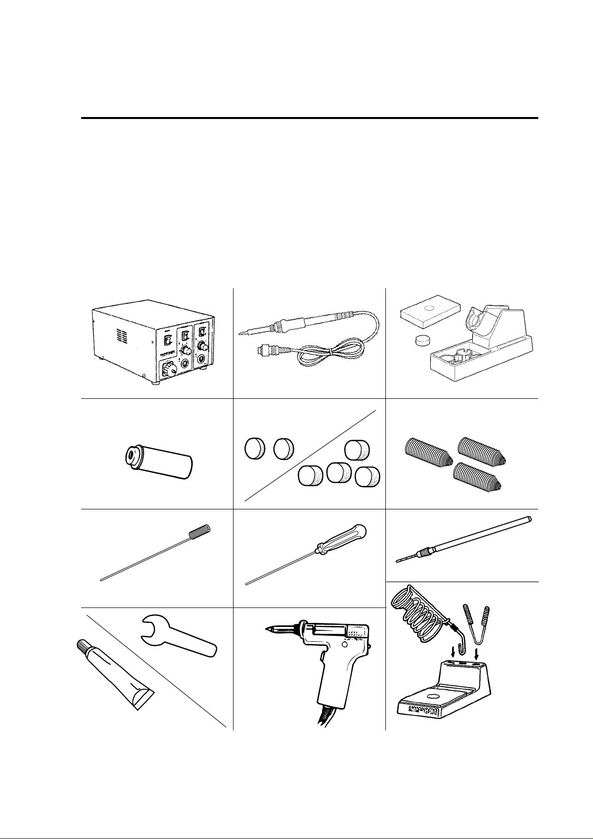
Packing List
Please check to make sure that all the items listed below
are included in the HAKKO 701 package.
Station…………………………………….1
Soldering Iron…………………………….1
Desoldering Gun………………………...1
Iron Holder for Soldering Iron…………..1
Iron Holder for Desoldering Gun……….1
Filter Pipe………………………………...1
Station
Soldering Iron Iron Holder for Soldering Iron
Ceramic Paper Filter (S)
Ceramic Paper Filter (S) .…………………………2
Ceramic Paper Filter (L)..…………………………4
Spring Filter...………………………………………3
Cleaning Pin (for ø1.0mm [0.04 in] nozzle)..……1
Cleaning Pin (for Heating Element)...……………1
Cleaning Drill (for ø1.0mm [0.04 in] nozzle).……1
Silicone Grease.……………………………………1
Spanner (for Desoldering Gun)..…………………1
Instruction Manual.…………………………………1
Filter Pipe
Cleaning Pin for ø1.0 mm (0.04 in) Nozzle
Spanner
Never use it for
*
soldering iron.
Silicone Grease
1
Ceramic Paper Filter (L)
Cleaning Pin for Heating Element
Desoldering Gun
Spring Filter
Cleaning Drill for ø1.0 mm (0.04 in) Nozzle
Iron Holder for
Desoldering Gun
Page 3
Precautions
In this instruction manual, "WARNING" and "CAUTION" are defined as follows.
WARNING
WARNING: Misuse may potentially cause death of, or serious injury to the user.
CAUTION : Misuse may potentially cause injury to the user or physical damage to the
objects involved.
For your own safety, be sure to comply with these precautions.
CAUTION
Remove the pump securing screws (M4 x 25 marked red)
from the bottom of the station.
Failure to do so may result in serious problems.
When the power is on, the tip and the nozzle temperature is
between 200˚C/392˚F and 480˚C/896˚F.
Since mishandling may lead to burns or fire, be sure to comply with
the following precautions.
•Do not touch the metallic parts near the tip and the nozzle, nearby plastic
parts and the spring iron holder .
•Do not use the product near flammable items.
•Advise other people in the work area that the unit can reach a very high
temperature and should be considered potentially dangerous.
•Turn the power off while taking breaks and when finished using the unit.
•Before replacing parts or storing the unit, turn the power off and allow the
unit to cool to room temperature.
To prevent damage to the unit and ensure a safe working
environment, be sure to comply with the following precautions.
•Do not use the unit for applications other than soldering or desoldering.
•Do not rap the desoldering gun against the work bench to shake off
residual solder, or otherwise subject the iron or the gun to severe shocks.
•Do not modify the unit.
•Use only genuine HAKKO replacement parts.
•Do not wet the unit or use the unit when your hands are wet.
•Set the ceramic paper filter (S) for the filter retainer (station), and the
ceramic paper filter (L) for the filter pipe (gun).
•Maintain the soldering iron or the desoldering gun and the station.
•While using the unit, don't do anything which may cause bodily harm
or physical damage.
2
Page 4
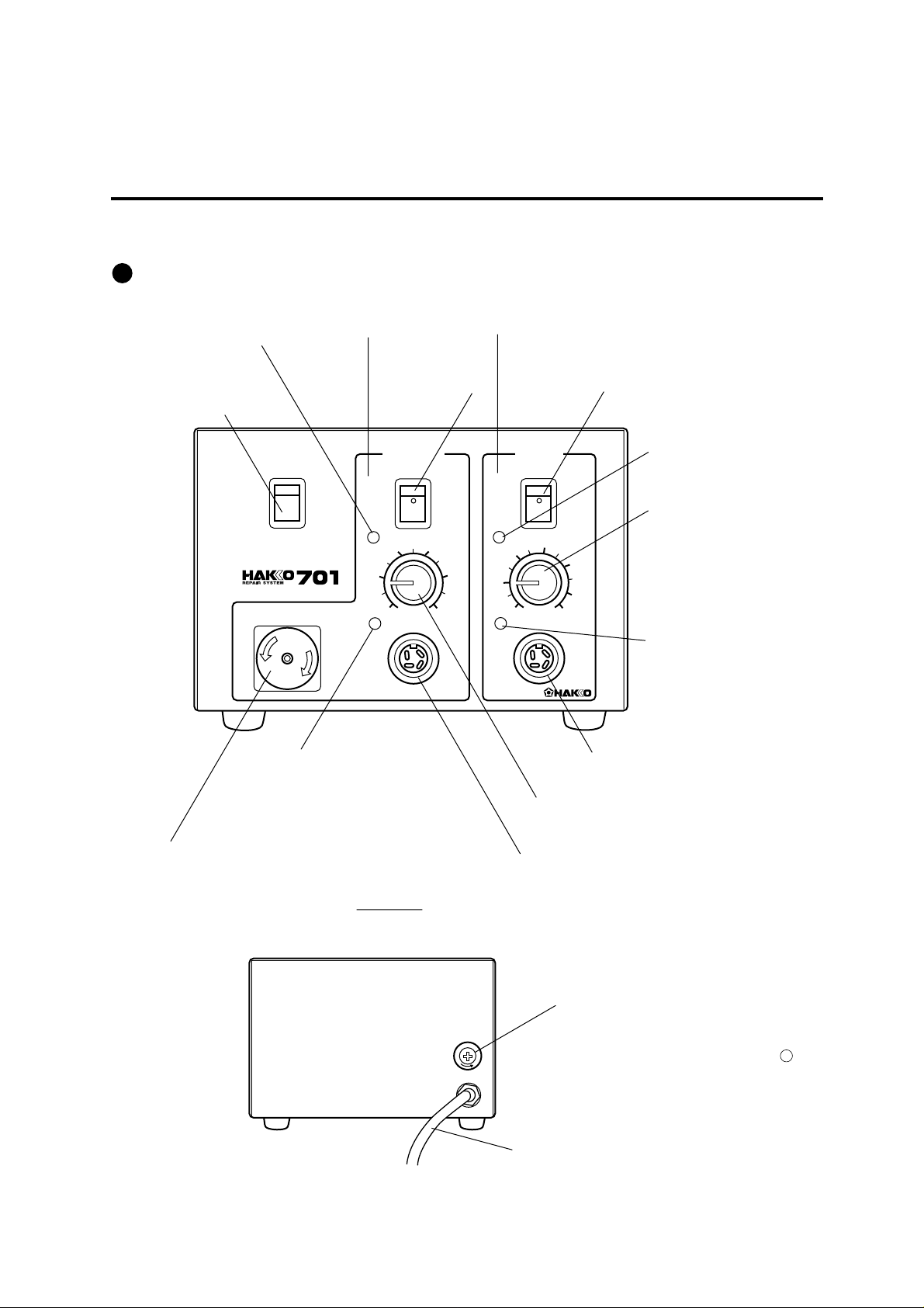
Part Names
Station
(Refer to p.23~26 for part nos.)
L.E.D. Lamp for
Desoldering
DESOLDER SOLDER
Power Switch
Lights up when the
power switch is turned to ON.
POWER
ON
OFF
VACUUM
N
C
E
L
P
O
O
S
E
CAL (Calibration) for
Desoldering
Used for calibrating the temperature
after replacing the heating element
and gun.
Vacuum Outlet Cap
Connects with the hose.
Set the ceramic paper filter(S)(No.A1009).
Filter inside the vacuum outlet cap is expendable.
Switch for
Desoldering
DESOLDER
34
2
1
CAL
ON
OFF
6
Switch for Soldering
L.E.D. Heater Lamp
SOLDER
ON
Blinks on and off when the
tip temperature reaches the
set temperature.
Temp. Control Knob
OFF
350
300
5
250
200
CAL
400
450
480
˚C
®
Provides the tip temperature
control.
CAL (Calibration) for
Soldering
Used for calibrating the temperature
after replacing the heating element,
soldering iron and tip.
Receptacle
Connector for the cord assembly of soldering iron
Temp. Control Knob
Pvovides the nozzle temperature control.
Receptacle
Connector for the cord assembly of desoldering gun
Fuse Holder
•u100,110V unit contain 125V-5A fuse.
•0120V unit contains 250V-5A (U) fuse.
S
E
U
F
3
•2220,230V unit contain 250V-2A fuse.
•2Australian 240V unit contains 250V-2A S fuse.
Power Cord
Page 5
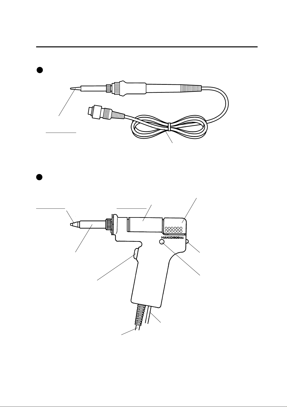
Soldering Iron (HAKKO 907 ESD)
Soldering Tip
Heats the solder and things which is soldered.
Expendable parts
Cord Assembly
Connects to the receptacle (station).
Desoldering Gun (HAKKO 809)
Nozzle
Transmits heat for melting solder.
Entrance for melted solder.
Expendable part
Heating Element
Inside requires cleaning.
Trigger
Squeeze to start absorption.
Do not pull the trigger before
fully heating the nozzle.
Cord Assembly
Connects to the receptacle (station).
Filter Pipe
Set the ceramic paper filter (L) (No. A1033).
Contains melted solder and flux using filters.
Filter are expendable parts.
Hose
Connects to the vacuum outlet cap (station).
Back Holder
Assembly
Secures the filter
pipe.
Release Knob
Push down to
remove the filter pipe.
Indicator
Indicates when
nozzle and heating
element need
cleaning and when
filters need replacing.
4
Page 6
Operation (Soldering)
CAUTION : The sponge is compressed. It will swell when moistened with water.
Before using the unit, dampen the sponge with the water and squeeze it dry.
Failure to do so may result in damage to the soldering tip.
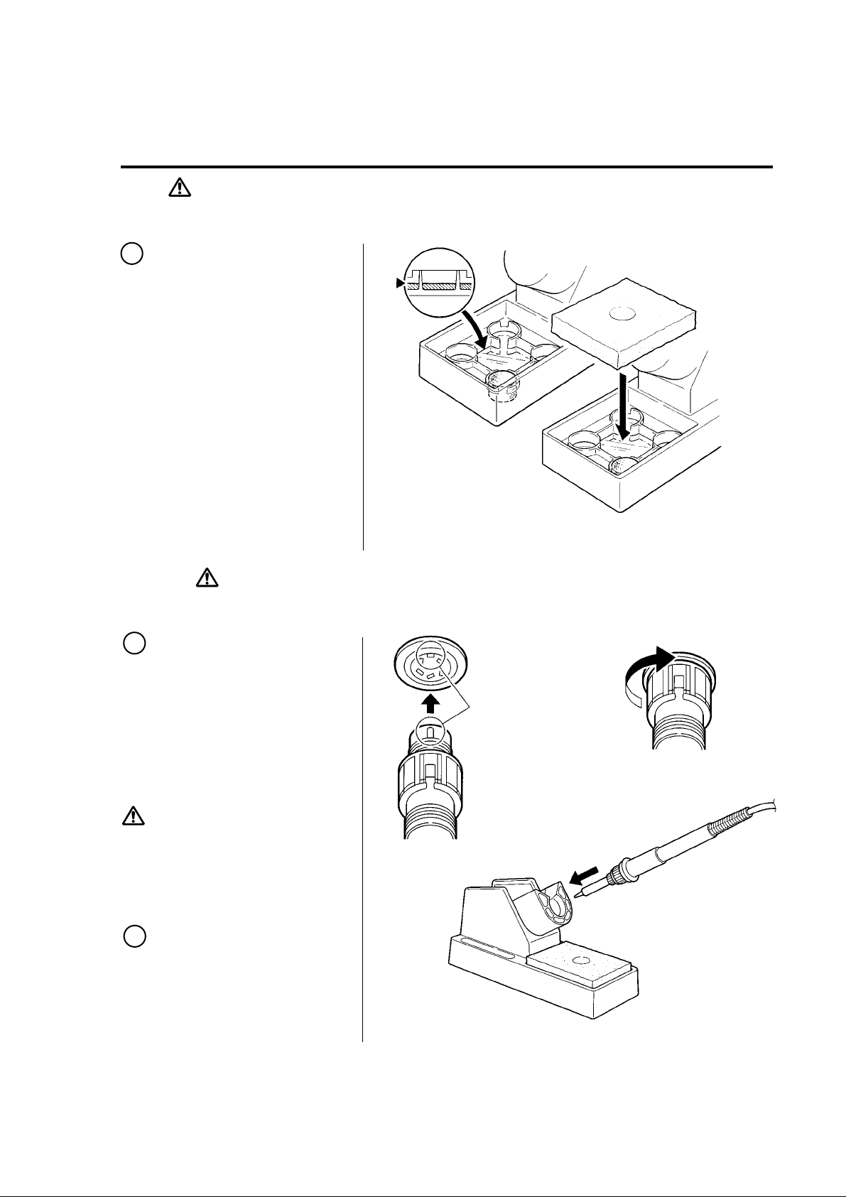
1 Assemble the iron
holder for soldering iron.
1. Small Cleaning Sponge
Dampen the small cleaning
sponge with water and then
squeeze it dry. Place it in one
of the 4 openings of the iron
holder base.
2. Add water to approximately the
level as shown.
The small sponge will absorb
water to keep the larger sponge
above it wet at all times.
3. Dampen the large cleaning
sponge and place it on the
iron holder base.
* The large sponge may be used alone
(w/o small sponge & water).
CAUTION : Be sure to turn off the switch before connecting or disconnecting
the soldering iron. Failure to do so may damage the P.W.B.
2 Connections
1. Place the soldering iron in the
iron holder.
2. Connect the cord assembly of
soldering iron
(HAKKO 907-ESD)
to the receptacle of soldering
iron (marked "solder").
3. Plug the power cord into the
power supply.
CAUTION
·Be sure to turn off the power switch
before connecting the plug.
·The entire unit is constructed of
conductive materials.
Always ground the unit.
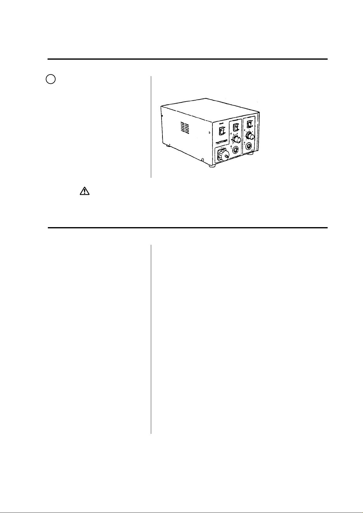
3 Set the temperature.
Set the temperature control
knob to the desired
temperature.
Receptacle
Align the grooves and pins,
and push straight in.
Turn clockwise firmly.
5
Page 7
4 Turn on the power
switch.
1. Turn the power switch to ON.
The switch should light up.
2. Turn the switch for soldering
iron to ON. The L.E.D. heater
lamp should light up.
3. The L.E.D. heater lamp blinks
on and off when the tip
temperature reaches the set
temperature. The unit is now
ready to perform soldering work.
CAUTION : The soldering iron must be placed in the iron holder when not in use.
Tip Care and Use
•Tip T emperature
•Cleaning
•When not in use
•After use
High soldering temperatures can degrade the tip.
Use the lowest possible soldering temperature.
The excellent thermal recovery characteristics ensure
efficient and effective soldering even at low temperatures.
This also protects the soldered items from thermal damage.
Clean the tip regularly with a cleaning sponge, as oxides
and carbides from the solder and flux can form impurities
on the tip. These impurities can result in defective joints
or reduce the tip's heat conductivity.
When using the soldering iron continuously, be sure to
loosen the tip and remove all oxides at least once a week.
This helps prevent seizure and reduction of the tip
temperature.
Never leave the soldering iron sitting at high temperature
for long periods of time, as the tip's solder plating will
become covered with oxide, which can greatly reduce the
tip's heat conductivity.
Wipe the tip clean and coat the tip with fresh solder.
This helps prevent tip oxidation.
6
Page 8
Operation (Desoldering)
Preparation–Assembly and Connection
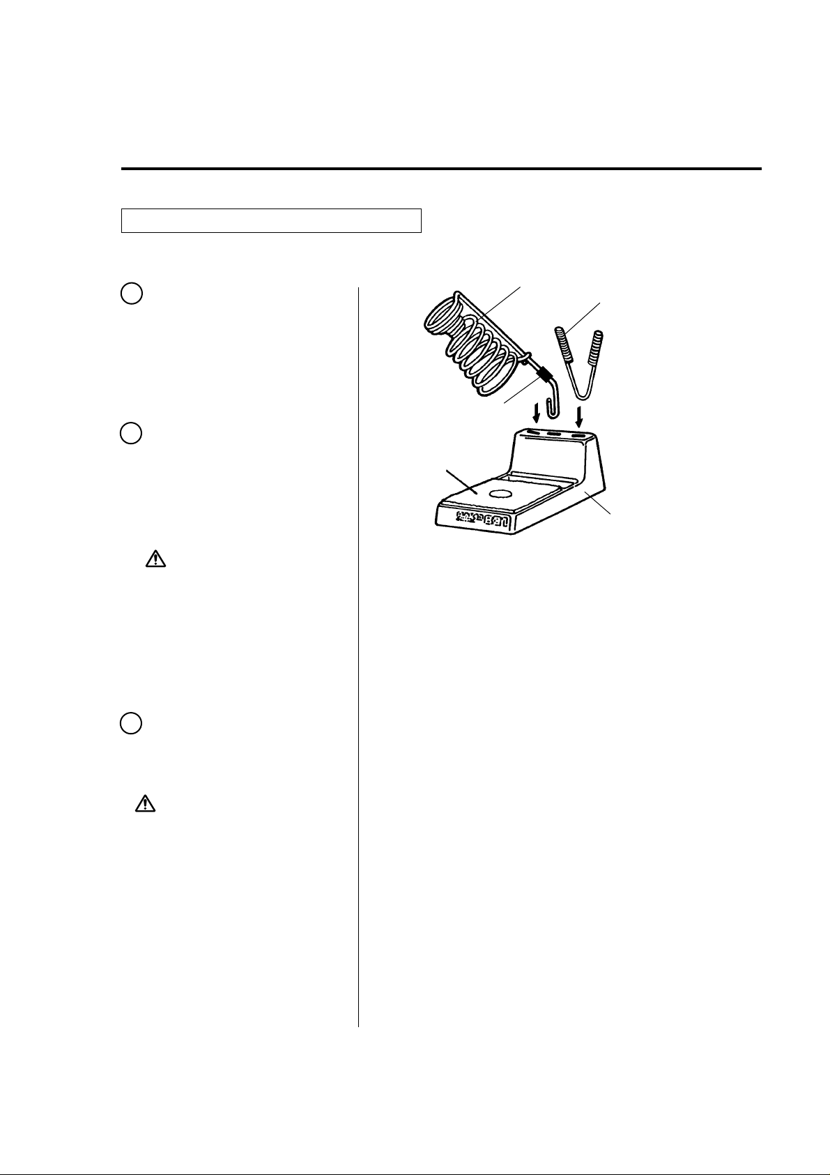
Assemble the iron holder on a flat surface.
1
Remove the pump securing
screws (M4 x 25 marked red)
from the bottom of the station.
Spring Iron Holder
(No. B1094)
Cleaning Pin Holder
(No. B1095)
2 Assemble the iron holder.
1. Set the spring iron holder and
cleaning pin holder in the iron
holder base.
2. Dampen the cleaning sponge
with water and then squeeze
it dry.
CAUTION
·The sponge is compressed. It will
swell when moistened with water.
Be sure to dampen the sponge with
water before use.
·Be sure to remove the round portion
of the sponge.
3 Insert the desoldering gun
and cleaning pins.
Fully insert the desoldering
gun into the spring iron holder.
CAUTION
The spring iron holder becomes
extremely hot during operation of the
desoldering gun. Do not touch the
spring iron holder during and
immediately after using the gun.
Tube (red)
Cleaning Sponge
Securely insert the
cleaning pin holder.
Iron Holder Base
7
Page 9
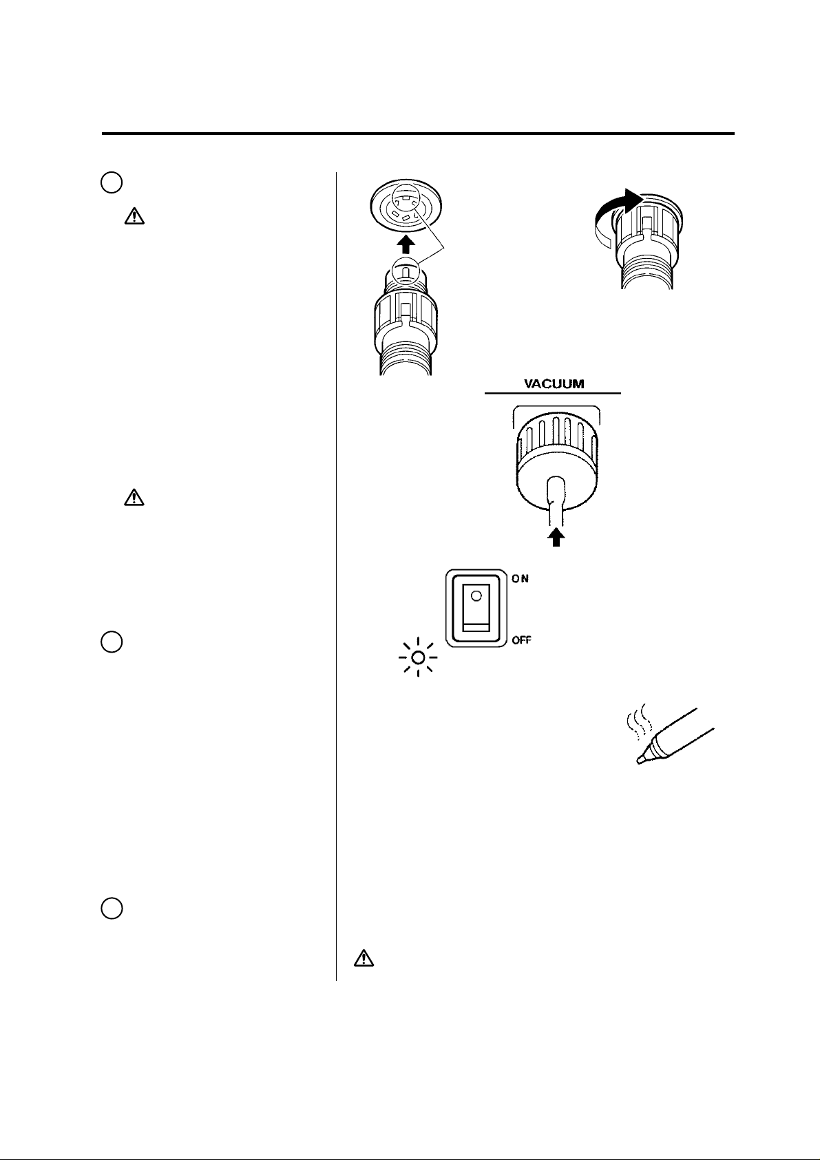
4 Connections
CAUTION
Be sure to turn off the power switch
before connecting or disconnecting
the cord assembly and the power
plug. Failure to do so may damage
the P.W.B.
1. Connect the cord assembly of
the desoldering gun (HAKKO
809) to the receptacle of the
desolder
2. Connect the hose to the
vacuum outlet cap (marked
"VACUUM").
3. Plug the power cord into the
power supply.
·Confirm that the power switch is set
in the OFF position, then connect the
power plug to the power source.76·
·The entire unit is constructed of
conductive materials. Always ground
the unit.
(marked "DESOLDER").
CAUTION
Insert the cord
assembly by keying
the plug to the key
on the receptacle.
Secure the plug by
turning it clockwise.
Fully insert the hose
into the vacuum
outlet cap.
5 Power switch
1. Turn the power switch to ON.
The power lamp should light
up.
2. Turn the switch for desolder to
ON. The nozzle begins to heat
up as soon as the switch is
turned to ON.
6 After turning the switch
to ON, wait 3 minutes
before beginning
desoldering operations.
The power lamp
lights up.
CAUTION
The nozzle heats up.
The desoldering gun must be placed in the iron
holder when not in use.
8
Page 10

Operation (Desoldering)
Desoldering
After turning the switch to ON,
wait 3 minutes before beginning
desoldering operations.
1 Set the temperature.
CAUTION
Always set the temperature to as
low as possible for the work being
done.
To more precisely set the
temperature, measure the
temperature at the nozzle
using a soldering iron
thermometer and adjust the
temperature control knob
accordingly.
We recommend the HAKKO
191 thermometer or HAKKO
192 soldering tester for
measuring the nozzle temperature.
The temperature can be adjusted between
380˚C (716˚F) and 480˚C (896˚F) with temperature
control knob.
Please refer to the chart below, and adjust
the temperature control knob.
knob
1 ~ 2
3 ~ 4
5 ~ 6
P.W.B.
Single-sided P.W.B.
Through-hole P.W.B.
Multilayer P.W.B.
Clean the tip of the nozzle.
2
Keep the solder-plated section
of the nozzle a shiny white by
coating it with a small amount
of solder.
If the tip of the nozzle is
coated with oxide, the
nozzle's heat conductivity
will be lowered.
Coating the tip with a
small amount of fresh
solder ensures maximum
heat conductivity.
9
Wipe away any oxide or old solder
from the nozzle using the hole in
the center of the sponge.
Page 11

3 Melt the solder.
1. Apply the nozzle to the
soldered part and melt the
solder.
CAUTION
Never allow the nozzle to touch the
board itself.
2. Confirm that the solder is
melted.
CAUTION
To confirm that all the solder is
melted,observe the inside of the
hole and the backside of the P.W.B.
If this is difficult to do, try slowly
moving the lead with the nozzle—oif
the lead moves, the solder is melted.
CAUTION
Never move the lead by force. If it
doesn’ot move easily, the solder isn’ t
yet fully melted.
4 Absorb the solder.
1. After confirming that the
solder is completely melted,
absorb the solder by
squeezing the trigger on
the gun.
Nozzle
P.W.B.
Solder
Lead
Slowly move
the lead with
the nozzle.
CAUTION
Never leave any solder remaining
inside the hole in the P.W.B.
2. After fully absorbing all the
solder, cool the soldering
junction in order to prevent it
from becoming resoldered.
5 Problems during
desoldering
If solder remains, resolder
the component and repeat
the desoldering process.
Absorb the solder by slowly
moving the lead back and
forth with the tip of the
nozzle.
10
Page 12

Operation (Desoldering)
Heated solder and flux can cause oxides to form and adhere
to the nozzle and the inside of the heating element. These
oxides not only lower the heat conductivity, but can also clog
the nozzle and heating element, resulting in a drop in suction
efficiency. Should there be a noticeable drop in suction efficiency
during operation, replace the filter and clean the nozzle and
heating element with the provided cleaning pin.
Cleaning during Operation
1 Observing the indicator
While looking at the indicator
and with the hole of the nozzle
open, pull the trigger and look
at the indicator. If it is red,
clean the nozzle and heating
element, empty the filter pipe,
and replace the filters. If the
indicator is blue, cleaning is
not necessary and operations
can be resumed.
CAUTION
The indicator will not operate accurately if the hole of the nozzle is closed or
if the solder in the hole of the P.W.B.
is not melted.
2 Replacing the filter
Replace the filter as shown
1 ~ 3 . During operation, the
filter pipe is very hot.
Wait until the filter pipe is cool
before replacing the filter.
We recommend keeping a
second filter pipe containing
new filters handy, and
replacing the installed filter
pipe with this backup filter
pipe.
Normal Abnormal Solution
If the indicator is more
than half red, replace
the filter and clean the
nozzle and the inside
Blue or slight
amount of red
can be seen.
CAUTION :
Replace the entire filter pipe
with the provided backup filter pipe.
More than half
of the indicator
is red.
If there is a noticeable drop in suction
efficiency, clean the nozzle and heating
element with the cleaning pin.
of the heating element.
(refer to p.15
Maintenance of the
Desoldering Gun)
Pull
Down
11
Page 13

Problems during Desoldering
A. The solder in the junction
is not sufficiently melted.
B. Suction power is dropping.
A. The solder in the junction is not sufficiently melted.
·Temperature is not high enough.
The following parts require a greater heat capacity to
desolder.
• Multilayer P.W.B.s, power supplies, ground planes in
through-hole P.W.B.s, high-capacity transistors, triacs
with heat radiation fins, tuner P.W.B. ground wires,
and large-scale transformer terminals.
Use a preheating oven or heating gun to heat the P.W.B. to
a temperature that won’t damage the board or its components [between 70˚C (160˚F) and 80˚C (180˚F)], then desolder. Do not increase the temperature of the gun by recalibration as this may damage the P.W.B. and its components.
·Nozzle is worn out.
• When the nozzle begins to wear out, the heating efficiency
begins to decline. Check the nozzle. If the solder plating
is damaged, or the nozzle is eroded, replace the nozzle.
(refer to p.15)
Post-operation Maintenance
To ensure a long service life, always
perform the following maintenance
procedures immediately after using
the HAKKO 701 unit.
B. Suction power is dropping.
• Replace the filters, and clean the nozzle and the inside
of the heating element. (refer to p.15~20, Maintenance
of the Desoldering Gun and Station )
·Air is leaking from the vacuum system.
Air leakage cannot be determined from the indicator.
Check the air-tightness of the following parts and replace
any that are worn.
a. Contact point of the
nozzle and heating
element
b. Front holder and nearby
c. O-ring in the back holder
d. Hose
e. Vacuum outlet cap
f. Packing and nearby parts
parts
Remove all solder from the inside of the nozzle and
heating element.
Clean the tip of the nozzle with the cleaning sponge,
then coat the tip with a fresh layer of solder to protect
the solder plating.
12
Page 14

Maintenance (Soldering Iron)
Inspect and Clean the Tip
CAUTION : Never file the tip to
remove oxide.
1. Set the temperature to 250˚C (482˚F).
2. When the temperature stabilizes, clean the tip with the cleaning
sponge and check the condition of the tip.
3. If there is black oxide on the solder-plated portion of the tip, apply
new solder (containing flux) and wipe the tip on the cleaning sponge.
Repeat until the oxide is completely removed. Coat with new solder.
4. If the tip is deformed or heavily eroded, replace it with a new one.76
Calibrating the Iron Temperature
The soldering iron should be
recalibrated after changing the iron,
or replacing the heating element
or tip.
1. Connect the cord assembly plug to the receptacle on the station.
2. Set the temperature control knob to 400˚C (750˚F).
3.
Turn the power switch to ‘ON’ and wait until the temperature stabilizes.
4. When the temperature stabilizes, use a regular or small cross point
screwdriver to adjust the screw (marked CAL at the station) until
the tip thermometer indicates a temperature of 400˚C (750˚F).
Turn the screw clockwise to increase the temperature and
counterclockwise to reduce the temperature.
* We recommend the HAKKO191/192 thermometer for measuring the tip
temperature.
Tips
The tip temperature will vary according to the shape of the tip. The preferred method of adjustment uses a tip
thermometer.
A less accurate method involves adjusting the temperature control knob according to the adjustment value for each tip.
Example : When using a 900M-T-H tip at 400˚C (750˚F),
the difference between this tip and a 900M-T-B is - 20˚C ( - 36˚F).
Set the temperature control knob to 420˚C (786˚F).
Refer to the chart for the correct adjustment values.
907
900M-T-0.8D
0˚C
900M-T-1.2D
0˚C
900M-T-1.6D
0˚C
900M-T-2.4D
0˚C
900M-T-3.2D
0˚C
900M-T-1.2LD
-10˚C/-18˚F
900M-T-SB
0˚C
900M-T-B
0˚C
13
0.6(0.024)
0.7(0.028)
0.5(0.02)
0.5(0.02)
0.5(0.02)
0.7(0.028)
(0.047)
ø1.2
(0.031)
ø0.8
(0.047)
ø1.2
(0.06)
ø1.6
(0.09)
ø2.4
(0.12)
ø3.2
(0.08)
ø2
3
(0.2)
5
(0.25)
6.5
25(0.98)
R0.2(0.008)
R0.5(0.02)
17(0.66)
17(0.66)
(0.1)
17(0.66)
14(0.55)
17(0.66)
CAUTION : Use only genuine HAKKO 907 replacement parts.
Never use tips for HAKKO DASH.
17(0.66)
17(0.66)
900M-T-LB
-10˚C/-18˚F
900M-T-0.5C
0˚C
900M-T-0.8C
-10˚C/-18˚F
900M-T-1C
900M-T-1CF*
0˚C
900M-T-1.5CF*
0˚C
900M-T-2C
900M-T-2CF*
0˚C
900M-T-3C
900M-T-3CF*
0˚C
900M-T-4C
900M-T-4CF*
0˚C
R0.2(0.008)
(0.02)
ø0.5
(0.031)
ø0.8
(0.04)
ø1
(0.06)
ø1.5
(0.08)
ø2
(0.1)
ø3
(0.16)
ø4
25(0.98)
45
45
60
60
45
45
45
15(0.6)
17(0.66)
15(0.6)
15(0.6)
17(0.66)
17(0.66)
17(0.66)
900M-T-K
+30˚C/+54˚F
900M-T-R
0˚C
900M-T-RT
0˚C
900M-T-SI
0˚C
900M-T-I
-10˚C/-18˚F
900M-T-H
-20˚C/-36˚F
900M-T-1.8H
-10˚C/-18˚F
900M-T-S4
0˚C
2(0.08)
3.5(0.13)
1.8(0.07)
(0.2)
ø5
45˚
15(0.6)
(0.2)
ø5.1
(0.08)
2
17(0.66)
(0.1)
3.2
(0.17)
ø4.2
2
(0.08)
2
17(0.66)
(0.08)
R0.2(0.008)
13(0.51)
R0.2(0.008)
17(0.66)
1.2(0.04)
(0.29)
7.5
25˚
19(0.74)
1(0.04)
(0.29)
7.5
25˚
14(0.55)
R0.25(0.01)
(0.08)
ø2
15(0.6)
•900M tip Out Diam ø6.5
Page 15

Checking for Breakage of the Heating Element,
Cord Assembly and Tip to Ground Resistance
Disconnect the plug and measure
the resistance value between the
connecting plug pins as follows.
If the values of 'a' and 'b' are outside
the above value, replace the heating
element (sensor) and/or cord
assembly. Refer to procedures
1 and 2.
Broken Heating Element
Disassembling the 907
4
3
2
1
Heating Element (Red)
Sensor (Blue)
a Between pins 4&5 (Heating Element) 2.5 - 3.5 (Normal)
b Between pins 1&2 (Sensor) 43 - 58 (Normal)
c Between pin 3&Tip Under 2
3
4
5
8
5
1. Turn the nut (1) counterclockwise and remove the tip enclosure (2),
the tip (3).
2. Turn the nipple (4) counterclockwise and remove it from the iron.
3. Pull both the heating element (6) and the cord assembly (11) out of
the handle (12). (Toward the tip of the iron.)
4. Pull the grounding spring (5) out of the D-sleeve.
Measure when the heating element is at room temperature.
1. Resistance value of heating element (RED) 2.5 - 3.5
2. Resistance value of sensor (BLUE) 43 - 58
If the resistance value is not normal, replace the heating element.
(Refer to the instructions included with the replacement part.)
After replacing the heating element,
1. Measure the resistance value between 1) pins 4 & 1 or 2 2) pins 5
& 1 or 2. If it is not , the heating element and sensor are touching.
This will damage the P.W.B.
2. Measure the resistance value 'a', 'b', and 'c' to confirm that the leads
are not twisted and that the grounding spring is properly connected.
7
9
6
2
1
12
10
11
Broken Soldering Iron Cord
There are two methods of testing
the soldering iron cord.
CAUTION
The LED heater lamp will flicker even
with a normal iron cord if the temperature
reaches 480˚C (896˚F).
Checking the Tip to Ground
Resistance
If the value of 'c' is over the above
value, remove the oxidization film by
lightly rubbing with sand-paper or
steel wool the points shown below.
1. Turn the unit ON and set the temperature control knob to 480˚C
(896˚F). Then wiggle and kink the iron cord at various locations along
its length, including in the strain relief area.
If the LED heater lamp flickers, then
the cord needs to be replaced.
2. Check the resistance between the pin of the plug and the wire on
the terminal.
Pin 1: Red pin 2: Blue pin 3: Green pin 4: White pin 5: Black
The value should be 0
the cord should be replaced.
. If it is greater than 0 or is ,
14
Page 16

Maintenance (Desoldering Gun)
Properly maintained, the HAKKO 809 desoldering gun should provide years of good service.
Efficient desoldering depends upon the temperature, and the quality and quantity of the solder
and flux. Perform the following service procedures as dictated by the conditions of the gun’os usage.
WARNING :
Servicing the Desoldering Gun
CAUTION
The desoldering gun will be extremely hot.
During maintenance, please wear gloves
and work carefully.
1 Inspect and clean the
nozzle.
1. Plug in the power cord, turn
the power switch On and let
the nozzle heat up.
2. Clean out the hole of the
nozzle with the nozzle
cleaning pin.
Since the desoldering gun can reach a very high temperature, please work carefully.
Except when cleaning the nozzle and heating element, always turn the power switch
off and disconnect the power plug before performing any maintenance procedure.
Cleaning with the nozzle cleaning pin.
The cleaning pin passes
completely through the hole.
Cleaning with the cleaning drill.
• Before cleaning
CAUTION
The cleaning pin will not pass
through the nozzle until the solder
inside the nozzle is completely
melted.
If the cleaning pin does not
pass through the hole in the
nozzle, clean with the
cleaning drill.
3. Check the condition of the
solder plating on the tip of the
nozzle.
If it is slightly worn, recoat the
tip with fresh solder to prevent
oxidation.
4. Check the condition of the
surface and inside hole of the
nozzle.
If either is worn or eroded, or
the inside diameter seems
unusually wide, replace the
nozzle.
CAUTION
The inside hole and the surface of
the nozzle is plated with a special
alloy. Should this alloy become
eroded by high-temperature solder,
the nozzle will not be able to maintain
the proper temperature.
15
• After cleaning
Pull the drill bit out straight without turning it.
solder plating
Diameter of hole is
widened through erosion.
Insert the bit while turning it clockwise.
CAUTION
If the cleaning drill is forced
into the nozzle, the drill bit
could break or be damaged.
CAUTION
Please use the proper sized
cleaning pin or cleaning drill
for the nozzle diameter.
Note
Unfortunately, it is often difficult to observe this condition.
Therefore, if desoldering efficiency goes down and all other parts appear to be OK, the
nozzle is probably eroded and
should be replaced.
Page 17

2 Disassemble the heating
element.
CAUTION
The heating element is very hot
during operation.
Heating Element
Nozzle
Remove the nut with the attached spanner.
Element Cover
Nut
3 Clean out the hole in the
heating element with the
provided cleaning pin.
CAUTION
Be sure the solder in the hole in the
heating element is completely heated,
before cleaning the hole.
1. If the cleaning pin cannot pass
through the hole, replace the
heating element.
2. Turn the power off after
cleaning.
4 Replace the filters.
1. When the filter pipe is cool to
the touch, push down the
release knob at the back of
the gun and remove the filter
pipe.
CAUTION
The filter pipe is very hot.
Scrape away all oxidation from the hole in the heating element until
the cleaning pin passes cleanly through the hole.
The cleaning pin passes cleanly
and completely through the hole.
Front Holder
Spring Filter
Ceramic Paper
Filter (L)
(No. A1033)
2. Examine the front holder.
3. Examine the spring filter.
4. Examine the ceramic paper
filter (L). (No. A1033)
Replace
Stiff and cracked.
Replace
Solder is collected in two-thirds of the spring filter.
Replace
Ceramic paper filter is stiff with flux and solder.
16
Page 18

5 Secure the filters.
1. Attach the spring filter to the
front holder.
2. Attach the front holder to the
filter pipe.
CAUTION
Be sure the front holder is correctly
aligned.
CAUTION
Use the ceramic paper filter (L) for
the filter pipe (gun). Using of the
ceramic paper filter (S) in the filter
pipe may cause to break or the
power to drop.
Ceramic Paper
Filter (L)
(No. A1033)
Attach the front holder to the filter pipe
so that it does not leak air.
Firmly press the back holder assembly
into the filter pipe in order to properly
seat the O-ring against the pipe.
6 Assemble the heating
element.
Attach the nozzle and
securely tighten the nut with
the attached spanner.
CAUTION
If the nut is loose, air will leak and
the temperature will drop.
17
Page 19

Replacing the Heating Element
WARNING
Unplug the power cord before
starting this procedure.
The resistance value of a working
heating element is 2-4
at 23˚C
(73˚F). If the value you get is
outside this range, replace the
heating element.
1 Disassemble the heating
parts.
2 Separate the housing.
3 Detach the terminal and
remove the heating
element.
4 Insert a new heating
element and reassemble.
(Heating element 24V-50W)
CAUTION
Before reassembling enclosure,
make sure connectors are completely
covered by the glass tube.
5 Recalibrate the tempera ture.
The resistance of new heating
element varies, resulting in
variations in operating tem peratures. It is necessary to
recalibrate the temperature
every time the heating element
is replaced.
1. Set the temperature control
knob to 1 and allow the gun
to warm up for 3 minutes.
2. Measure the tip with a tip
thermometer. Using a straight edge (-) or small cross point
screwdriver, adjust the tem perature calibrator (marked
“CAL”) until the nozzle tem perature reads 380˚C(716˚F).
Turn the temperature calibrator
clockwise to increase the
temperature and counter clockwise to reduce the tem perature.
Remove the filter pipe.
Housing
Unscrew the screws.
Detach
the terminal.
Glass Tube
Cover the glass tube
on the connecting part.
Bend the lead
before inserting it.
Position the leads in groove
and press them into place.
Be careful that the leads do not
get caught in the housing.
18
Page 20

Maintenance (Station)
Cleaning the inside of the Filter Case
1 Replace the ceramic
paper filter (No. A1009).
Remove the ceramic paper
filter and inspect it. If it is stiff
with flux, replace it.
VACUUM
Filter Retainer
Ceramic Paper
Filter (S)
(No. A1009)
Remove the filter retainer
and push out the ceramic
paper filter.
2 Reassemble the filter case.
CAUTION
Set the ceramic paper filter (S) for
the filter retainer (station).
Using the ceramic paper filter (L) in
the filter retainer may cause to break
or the power to drop.
19
Ceramic Paper
Filter (S)
Secure the vacuum outlet cap.
(No. A1009)
Apply silicone grease to the O-ring (S20) and securely tighten
the vacuum outlet cap to prevent air leakage.
Page 21

Cleaning the Pump
WARNING
Unplug the power cord before
starting this procedure.
1 Disassemble the pump
heads.
1. Remove the rear panel.
2. Remove the cover.
Remove the pump head from
each side of the pump.
2 Clean the pump head.
1. Remove the valve plate and
fixing plate.
2. Remove any flux adhering to
the plates.
CAUTION
If the fixing plate is difficult to remove,
apply hot air to it to warm it up.
Never use excessive force to remove
the plate as it is easy to bend, and a
bent plate will allow air to leak out and
reduce solder vacuuming efficiency.
Clean the pump head
and fixing plate.
Fixing Plate
Valve Plate
Pump Head
Exhaust Filter
CAUTION
Clean the plates only with alcohol
or thinner.
Replace
If the valve plate is bent or stiff,
replace it.
3. If the exhaust filter is dirty,
replace it.
3 Assemble the pump heads.
Reassemble the valve plate
and fixing plate.
CAUTION
When assembling the pump, be sure
to check for air leaks.
Pump Head
Be sure the parts are
aligned correctly.
Valve Plate
Fixing Plate
20
Page 22

Troubleshooting Guide
Soldering and Desoldering
Soldering
·Power lamp does not light up.
• Is the power cord plugged in correctly?
Securely insert the power cord into the power supply.
• Is the fuse blown?
Determine why the fuse blew and eliminate the cause,
then replace the fuse.
a. Is the inside of the soldering iron or desoldering gun
short-circuited?
b. Is the grounding spring touching the heating element?
c. Is the heating element lead twisted and short-circuited?
·The heater lamp lights up but the tip does not
heat up.
• Is the soldering iron cord broken ?
Refer to ‘rChecking for breakage of the cord assembly.’y
(P.14)
• Is the heating element broken?
Refer to ‘rChecking for breakage in the heating element.’r
(P.14)
·The tip heats up intermittently.
• Is the soldering iron cord broken?
Refer to ‘rChecking for breakage of the cord assembly.’y
(P.14)
21
·The tip is not wet.
• Is the tip temperature too high?
Set an appropriate temperature.
• Is the tip clean?
Refer to ‘rTip Care and Use’i(P.6)
·The tip temperature is too low.
• Is the tip coated with oxide?
Refer to ‘rInspect and clean the tip’n(P.13)
• Is the iron calibrated correctly?
Recalibrate.
·The tip can not be pulled off.
• Is the tip seized?
Is the tip swollen because of deterioration?
Replace the heating element and the tip.
·The tip doesn't hold the desired temperature.
• Is the iron calibrated correctly?
Recalibrate.
Page 23

Desoldering
·Pump does not operate.
• Is the cord assembly properly connected?
Reconnect the cord assembly.(refer to p.8)
• Is the nozzle or hole in the heating element
clogged?
Clean it.(refer to p.15)
·Solder is not being absorbed.
• Is the spring filter full of solder?
Replace it with a new one.(refer to p.16)
• Is the ceramic filter hardened?
Replace it with a new one.
• Is there a vacuum leak?
Check the connections and replace any worn parts.
(refer to p.12)
·The nozzle does not heat up.
• Is the desoldering gun cord assembly properly
connected?
Reconnect it.(refer to p.8)
• Is the heating element damaged?
Replace it. (refer to p.18)
Note : When repairs are needed please send both the
desoldering gun and the station to your sales agent.
WARNING :
If the power cord is damaged, it must be replaced by
the manufacturer, its service agent or similarity
qualified person in order to avoid personal injury or
damage to the unit.
22
Page 24

Parts List (Station)
Truss Screw
M 4 ~6 (8)
Pan Head Screw
with Washer
M 3 ~6
24
25
26
27
21
23
Pan Head Screw
with Washer
M 3 ~6 (4)
22
20
Pan Head Screw
with Washer
M4 ~8
External Tooth Lock Washer
nominal size 4
19
Pan Head
Screw
with Washer
(w/Spring Washer)
18
External
Tooth Lock
Washer
nominal size 5
16
17
14
15
Pan Head Screw
with Washer
M4 ~30
Pan Head
Screw
with Washer (w/Spring, Plain Washer)
M5 ~8 (3)
Pan Head Screw
with Washer
M3 ~6 (8)
13
Item No.
Part No. Part Name Description
14
B2090 P.W.B. (for Desoldering) w/potentiometer
B2063 Hose Assembly
15
16
B2064 Pump Assembly
B2091
Transformer 100-24V
B2092
17
18
19
20
21
22
Item No.
23
24
25
26
27
28
29
30
31
32
33
34
35
36
Transformer
B2093
Transformer
B2094
Transformer
B1208
Cord Stopper
B1204
Rubber Stopper set of 4
B2096
Cover
Fuse Holder
B1041
Fuse Holder
B1134
Fuse
B1236
B1257
Fuse
B1132
Fuse
B1133
Fuse
Part No. Part Name Description
Power Cord
B2068
Power Cord
B2079
Power Cord
B2081
B2082
Power Cord
B2083
Power Cord
B1053
Balance Weight
B1312
Crank w/Bearing
B1057
Ring for Bearing
B2060
Crank Shaft
B2059
Pump Frame
B2058
Motor
B2085
Diaphragm Setting Plate
A1013
Diaphragm set of 2
B1056
Fixing Plate
A1014
Valve Plate set of 2
B1050
Pump Head w/Hose Connector
B1059
Exhaust Filter set of 2
B1313
Filter Retaining Pin
120-24V
110-24V
220-24, 230-24, 240-24V
w/o Fuse
w/o Fuse/Australian 240V
125V-5A /100, 110V
250V-5A (U) /120V
250V-2A /220,230V
250V-2A S /Australian 240V
3 Core & American Plug
3 Core But No Plug
3 Core & Australian Plug
3 Core & BS Plug
3 Core & European Plug
Pan Head Screw
with Washer
M 4 ~10 (8)
23
36
35
Flat Head Screw
M 4 ~12 (2)
33
34
Hexagon Socket Set Screw
M 4 ~6
30
Flat Head Screw
M 4 ~8 (4)
32
31
28
29
Item No.
Part No. Part Name Description
1
B1029 Vacuum Outlet Cap
A1009
2
3
4
5
6
7
Ceramic Paper Filter (S) 10 pcs.
B1063
Filter Retainer
O-ring (S20)
B1034
B1031
Vacuum Outlet Retainer w/O-ring (S20)
B1064
Filter Case Joint
B1036
Receptacle (for Desoldering)
Spring Washer
nominal size 4 (4)
Hexagon Nut
M 4 (4)
Item No.
8
9
10
11
12
13
Spacer
nominal size
M 4 ~25
12
Pan Head Screw (marked red)
M 4 ~25
Part No. Part Name Description
B1486
Knob
B1487
Power Switch
B2101
Receptacle (for Soldering)
B1084
Switch
B2095
Chassis
B2089
P.W.B. (for Soldering) w/potentiometer
6
11
11
8
9
8
10
5
4
7
3
2
1
24
Page 25

1
2
Parts List (Desoldering Gun / Iron Holder)
3
5
6
4
20
Pan Head Screw (Sus)
M 2.6 x 7(3)
19
18
7
17
25
8
9
11
Tapping Screw
M 3 x 5
Pan Head Screw
M 2.6 x 3
16
15
HAKKO 809
Item No.1Part No. Part Name Description
A1314 Front Holder
A1030 Spring Filter 10 pcs.
2
A1033 Ceramic Paper Filter (L) 10 pcs.
3
B2073 Filter Pipe w/Front Holder & Filters
4
A1012 O-ring (p.12)
5
B1018 Back Holder Assembly w/O-ring (p.12)
6
B1019 Release Knob
7
B1020 Spring for Release Knob
8
B2074 Housing w/screws
9
B1023 Hose
10
A1319 Packing
11
21
22
10
23
24
Item No. Part No. Part Name Description
12
B1025 Cord Assembly w/Micro Switch & Plug
13
B1024 Cord Holder set of 4
14
B1022 Cord Stopper
15
B1026 Micro Switch
16
B1021 Trigger
17
A1313 Heating Element 24V, 50W
18
A1003 Nozzle S ø1.0 (0.04 in)
19
B1723 Element Cover
B1724 Nut
20
B1094 Spring Iron Holder
21
B1095 Cleaning Pin Holder
22
A1042 Cleaning Sponge
23
B1470 Iron Holder Base
24
B2100 Spanner
25
25
12
14
Tapping Screw
(Not Fluted Point)
M 3 x 8(2)
13
9
Pan Head Screw
M 3 x 8(3)
Page 26

·Replacement Parts
No. A1002, A1003 No. A1004~A1007
ø.A
ø.B
Part No.
A1002
A1003 Nozzle S Ø1.0 mm (0.04 in )
A1004 Nozzle Ø0.8 mm (0.03 in )
A1005 Nozzle Ø1.0 mm (0.04 in )
A1006 Nozzle Ø1.3 mm (0.05 in )
A1007 Nozzle Ø1.6 mm (0.06 in )
Part. Name / Specification
Nozzle S Ø0.8 mm (0.03 in )
ø.A
ø.B
ø A
0.8 (0.03 in)
1.0 (0.04 in)
0.8 (0.03 in)
1.0 (0.04 in)
1.3 (0.05 in) 3.0 (0.12 in)
1.6 (0.06 in) 3.0 (0.12 in)
1.8 (0.07 in)
2.0 (0.08 in)
2.3 (0.09 in)
2.5 (0.1 in)
ø B
Parts List (Iron/Iron Holder)
HAKKO 907ESD
Item No. Part No. Part Name Description
1 B1784 Nut
2 B1786 Tip Enclosure
3 Soldering Tip Sec. P. 13
4 B2022 Nipple
5 B2032 Grounding Spring
6 A1321 Heating Element Old part No.900M-H,900L-H
7 B2028 Terminal Board
8 B2024 Handle w/Handle Cover, E.S.D.
9 B2027 Handle Cover
10 B2031 Cord Bushing
11 B2030 Cord Asse'y E.S.D.
Part No.
B1215
B1086
B1087
B1088
B1089
B1302
B1303
B1304
B1305
Part. Name / Specification
Cleaning Pin for Heating Element
Cleaning Pin for Ø0.8 mm (0.03 in) Nozzle
Cleaning Pin for Ø1.0 mm (0.04 in) Nozzle
Cleaning Pin for Ø1.3 mm (0.05 in) Nozzle
Cleaning Pin for Ø1.6 mm (0.06 in) Nozzle
Cleaning Drill for Ø0.8 mm (0.03 in) Nozzle
Cleaning Drill for Ø1.0 mm (0.04 in) Nozzle
Cleaning Drill for Ø1.3 mm (0.05 in) Nozzle
Cleaning Drill for Ø1.6 mm (0.06 in) Nozzle
Silicone GreaseA1028
Specifications
Name
Power Consumption
Station
Output Voltage
Vacuum Generator Vacuum pump,
Vacuum Pressure (Max)
Suction Flow
Outer Dimensions
(W x D x H)
Weight
·Specifications are subject to change without notice.
HAKKO 701
150W
Station
24V~
double cylinder type
600mmHg (24in. Hg)
15 /min.
190 x 250 x 130 mm
(7.48 x 9.84 x 5.12 in)
Approx. 5.0 kg (11.02 lbs.)
Iron Holder
Item No. Part No. Part Name
1 C1142 Iron Holder
2 B2021 Iron Receptacle
3 B2019 Iron Holder Base
4 A1042 Cleaning Sponge
Soldering Iron
Part Name HAKKO 907ESD
Part No. C1144
Power Consumption 24V ~ 50W
Temperature Range 200˚C ~ 480˚C / 392˚F~ 896˚F
Temperature Stability ±
±
Tip to Ground Resistance
Tip to Ground Potential
Cord Assembly 1.2m (4 ft.)
Total Length
(w/o cord)
Weight (w/o cord) 44g
Desoldering Gun
Part Name
Part No.
Power Consumption 24V ~ 50W
Temperature
Nozzle to Ground Resistance
Nozzle to Ground Potential
Cord/Hose
Outer Dimensions(W x H)
Weight(w/o cord, hose)
2
1
4
3
10˚C / ±18˚F of the set temperature
0.5˚C / ±0.9˚F of tolerance at idling time
Under 2
Under 2mV (TYP. 0.6mV)
190mm (7.5 in.)
(0.09 lbs.)
HAKKO 809
C1183
380˚C ~ 480˚C (716˚F ~ 896˚F)
Under 2
Under 2mV (TYP. 1.2mV)
1.2m (4 ft.)
135 x 174 mm (5.31 x 6.85 in)
Approx. 200g (0.44 lbs.)
26
Page 27

Wiring Diagram
701 P.W.B.
blue
1
24V
white
4
Transformer
Motor
Power Cord
TRANS
TRANS
2
H2
1
M2 M1 TR
1
2
1
2
H1
1
4
3
2
Receptacle
1
3
1
3
TRANS
TH1 TH2 H4 H3
1
2
Receptacle
TRANS
4
1
3
1
5
4
3
3
1
5
4
1
2
Power Switch
Fuse Holder
®
HEAD OFFICE
4-5, SHIOKUSA 2-CHOME, NANIWA-KU, OSAKA, 556 JAPAN
TEL: (06) 561-3225 FAX: (06) 561-8466
TLX: HAKKOOSA J65274
OVERSEAS AFFILIATES
U.S.A.: AMERICAN HAKKO PRODUCTS, INC.
25072 ANZA DR. SANTA CLARITA, CA 91355, U.S.A.
TEL: (805) 294-0090 FAX: (805) 294-0096
Toll Free (800)88-HAKKO
4 2 5 5 6
S'PORE: HAKKO PRODUCTS PTE., LTD.
1, GENTING LINK #02-04, PERFECT INDUSTRIAL
BUILDING, SINGAPORE 349518
TEL: 7482277 FAX: 7440033
27
HONG KONG: HAKKO DEVELOPMENT CO., LTD.
ROOM 804 EASTERN HARBOUR CENTRE,
28 HOI CHAK STREET, QUARRY BAY, HONG KONG.
TEL: 2811-5588 FAX: 2590-0217
PHILIPPINES: HAKKO PHILS TRADING CO., INC.
NO. 415 WINDSOR TOWER CONDOMINIUM,
163 LEGASPI ST., LEGASPI VILLAGE MAKATI,
METRO MANILA, PHILIPPINES
TEL: 2-810-07-12 FAX: 2-810-76-49
MALAYSIA: HAKKO PRODUCTS SDN BHD
MALAYSIA HEAD OFFICE: PETALING JAYA
LOT 35/1 THE HIGHWAY CENTRE JALAN 51/205 46050
PETALING JAYA WEST MALAYSIA
TEL: 03-7941333 FAX: 03-7911232
PENANG BRANCH: TEL: 04-644 6669 FAX: 04-644 8628
JOHORE BAHRU BRANCH: TEL: 07-236 7766 FAX: 07-237 4655
Apr. 1996
May. 1996
 Loading...