

Page 1
FEEDER WITH
SOLDER CUTTING FUNCTION
●
Thank you for purchasing the Hakko 374 Self Feeder.
Please read this manual carefully before operating the
Hakko 374. Store the manual in a safe, easily accessible
place for future reference.
●
TABLE OF CONTENTS
SAFETY INSTRUCTIONS / SPECIFICA TIONS............................... 1
P A RT NAMES (FEED CONTROLLER UNIT) .................................. 2
P A RT NAMES (IRON SIDE), ASSEMBLY (IRON SIDE)..................3
ASSEMBL Y (FEED CONTROLLER UNIT) ...................................... 4
OPERATION .................................................................................... 5
MAINTENANCE ............................................................................... 6
OPTIONAL FEEDER PEN ............................................................... 7
OPTIONS AND REPLACEMENT PAR TS ........................................ 8
P AR TS LIST............................................................................... 9, 10
TROUBLESHOOTING ................................................................... 11
Page 2
SAFETY INSTRUCTIONS
■To avoid injury, do not attempt to assemble
while the soldering iron is hot.
■The cutting plate is sharp. Be careful not to cut
your fingers.
■When resin core solder that has been cut is
not used, the properties of the resin (flux) may
deteriorate with time.
■Once the solder has been cut and is inside the
guide pipe, the heat from the soldering iron may
accelerate the deterioration of the resin (flux).
Use solder that is inside the guide pipe as soon
as possible.
■Do not damage the guide pipe by bending or
twisting it.
SPECIFICATIONS
■Do not allow the tube to be bent at a severe
angle. Otherwise, it will become clogged with
solder.
■Keep the cutting blade, driving pulley, and
following pulley clean of solder and flux using
a brush or other suitable cleaning device.
■The switch input is no-voltage input. Do not
apply voltage to the switch jack.
■Periodically remove the nozzle and clean off
any accumulated flux.
■Do not damage the return length adjustment
knob by turning it with excessive force.
Power consumption
Motor rating
Solder diameter
Solder feed time
Solder feed speed
Solder feed quantity
Solder return quantity
Outer dimensions
Weight
*Specifications and design subject to change without notice.
6 W
24V DC, 3.2 W
0.6, 0.8, 1.0, 1.2, 1.6 mm
(0.02, 0.03, 0.04, 0.05, 0.06 in.)
0 to 7 sec.
4.5 to 26 mm/sec.
(0.18 to 1.02 in./sec.)
0 to 182 mm
(0 to 7.17 in.)
0 to 5 mm
(0 to 0.2 in.)
107(W) × 106(H) × 215(D) mm
(4.2(W) × 4.2(H) × 8.5(D) in.)
1.6 kg (3.5 lb.)
(fixed speed)
●●
●Solder diameters
●●
The solder diameters that can be used with the
Hakko 374 are shown in the table below . Certain
parts may need to be changed to accommodate
the desired diameter. See “Changing the solder
diameter” on page 4 for details.
Up to 1-kg bobbins of solder can be used.
●●
●Soldering irons
●●
Soldering iron
Hakko 900M
(used with Hakko 926, 927, and 928)
Hakko 900L
(used with Hakko 926, 927, and 928)
Hakko 902
(used with Hakko 931 and 932)
Hakko 904 (used with Hakko 929)
Hakko Dash
Hakko Mach
Hakko 907 (used with 936 and 937)
Hakko 908 (used with 936 and 937)
I
Comments
Only when footswitch is used.
1
Page 3
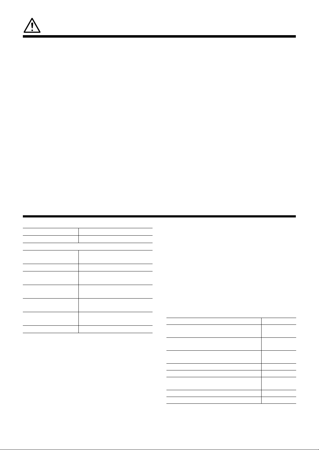
PART NAMES
●●
●Feed controller unit
●●
Switch jack
Mode switch
Feed time control knob
Feed speed control knob
Feed unit cover
Power switch
Following
pulley asse’y
Arm
AA'
Cutting blade
Driving pulley shaftFollowing gear shaft
Following pulley set screw
Driving
pulley asse’y
Feed nozzle
set screw
Feed nozzle
connection hole
Arm mounting screw
Tension adjusting screw
Return length adjusting knob
A'
Driving pulley
Driving pulley set screw
Supply nozzle
Motor mounting
plate
Following pulley
Stopper
A
Arm support shaft
Arm
Solder
bobbin shaft
2
Page 4
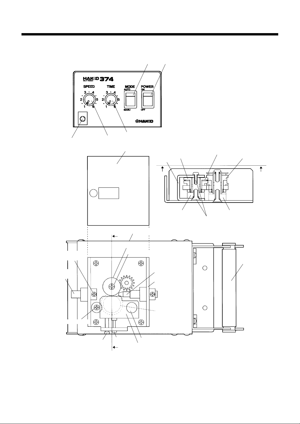
PART NAMES (IRON SIDE)
G
The guide pipe assembly and the tube unit are optional.
Select in accordance with the soldering iron and solder diameter to be used. (See page 8.)
●●
●Guide pipe assembly
●●
Guide pipe locking nut
Nozzle
Guide pipe
Guide pipe
support plate
Joint
●●
●Tube unit
●●
Tube
Feed switch
Feed nozzle
Attachment
Mini plug
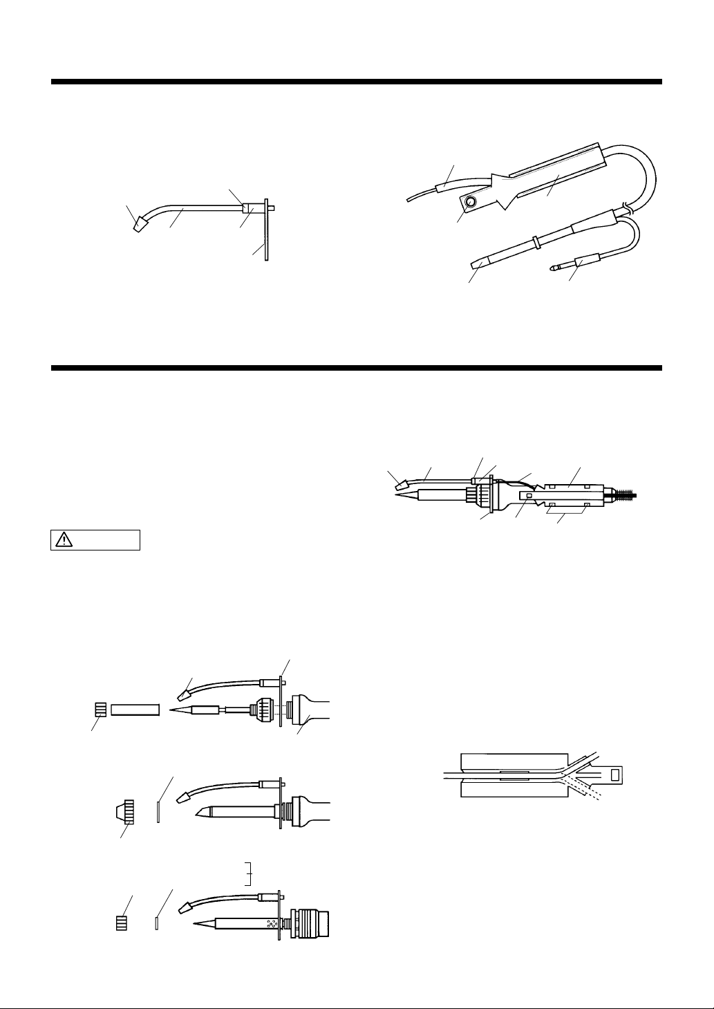
ASSEMBLY (IRON SIDE)
Make sure the selected guide pipe assembly or tube unit matches the soldering iron and solder diameter to be used.
(1)Attaching the guide pipe
assembly
The guide pipe assembly is attached between the
nipple (or nut) and the handle. Depending on the type
of soldering iron, a washer may be necessary. See
the figures below.
CAUTION
●To avoid injury, do not attempt to assemble while the
soldering iron is hot.
●Do not damage the guide pipe by bending or twisting it.
●Do not allow the tube to be bent at a severe angle.
Otherwise, it will become clogged with solder.
Hakko 900
Hakko Dash
Hakko 907 and 908
Nut
Nozzle
Guide pipe assembly
Handle
(2)Attaching the tube unit
Guide pipe
Nozzle
uide pipe support plate
(a) Attach the guide pipe assembly to the tube. The
tube is double structure. Insert the inner tube into
the joint and pass the outer tube over the outside
of the joint so that it covers the threaded portion.
Do not bend the tube.
(b) Attach the attachment to the soldering iron
Note) The attachment is not necessary when using the
1. Decide from which side of the attachment you will pass
the tube. Then, position the attachment so that the
tube connects to the guide pipe as straight as possible.
Guide pipe locking nut
Joint
Feed switch
Hakko Mach I.
Rear view of attachment
Attachment
Tube
Secure with clips
Hakko 902 and 904
Nipple
Hakko Mach I
Wave washer (No.B2684)
Stopper
Nut
918 - No.B2685
920
921 No.B2686
(
922
The tube can be passed through either the left or the
right side of the attachment. When changing the tube,
be careful not to damage the internal wiring.
)
2. Secure the attachment with the handle and the
adhesive tape on the rear of the attachment.
Refer to the figure above and be sure to attach the
attachment and the guide pipe at the correct angle.
3
Page 5

ASSEMBLY (FEED CONTROLLER UNIT)
Feed nozzle
set screw
Feed nozzle
connection
hole
Arm mounting
screw
Tension adjusting
screw
Driving pulley set screw
Supply
nozzle
Following pulley
Following
pulley
set screw
Stopper
Arm support shaft
Arm
Solder
bobbin
shaft
(1)Connect the feed nozzle
Insert the feed nozzle into the feed nozzle connection
hole and tighten the set screw. Do not tighten the set
screw excessively or you may crack the tube.
(2)Connect the mini plug
Insert the mini plug into the jack on the front of the
station. When use the Mach-
I, insert the footswitch
plug into the jack on the front of the station.
(3)Setting the solder
If there is any solder in the tube, remove it before
installing the new solder.
(4)Changing the solder
diameter
The following parts may need to be changed in order
to accommodate a change in the solder diameter or
type of soldering iron used.
Driving pulley assembly
Following pulley assembly
Supply nozzle
Guide pipe assembly
Tube unit
Change these parts as necessary according to the
procedure below.
CAUTION
The position of the stopper was set at the factory before
shipping. Do not move the stopper.
(a) Turn the power OFF . Loosen the tension adjusting
screw and the arm mounting screw, open the arm,
and remove any solder remaining in the tube.
(b) Remove the arm support shaft and remove the
arm assembly.
(c) Remove the following pulley set screws (two: top
and bottom) and change the following pulley.
(a) Pass the solder bobbin shaft through the solder
bobbin and attach the shaft to the rear of the
station. As shown below, attach the shaft so that
the solder is fed from the top of the bobbin.
(b) Pass the solder through the supply nozzle.
(c) Turn the power switch ON and set the mode to
MANUAL .
(d) While pressing the feed switch (or footswitch), the
solder is fed through the feed nozzle.
(e) While pressing the feed switch (or footswitch),
insert the tip of the solder between the driving
pulley and the following pulley.
(d) Remove the driving pulley set screw and change
the driving pulley.
NOTE) Install both the top and bottom oil-less washers
so that the black side of each is facing upward.
(See parts list.)
(e) Adjust so that the gears mesh properly and tighten
the tension adjusting screw until the stopper screw
touches the left end of the notch (screw hole) in
the motor mounting plate.
(f) Tighten the arm mounting screw.
(5)Vertical mounting
The Hakko 374 can be mounted vertically.
Mount as shown in the figure.
46 mm
(1.8 in.)
2-ø4.2 mm
(0.08-ø0.17 in.)
4
Page 6
OPERATION
To feed the solder, simply press the feed switch (or foot-switch). Details are explained below.
(1)Mode
AUTO MODE
In AUTO MODE, the solder is fed at the specified
speed for the specified amount of time regardless of
how long the feed switch is pressed.
MANUAL MODE
In MANUAL MODE, while pressing the switch the
solder is fed at the specified speed.
(2)Setting the feed time and
feed speed
Set the feed rate before setting the feed time. The
feed speed setting is effective in both AUTO and
MANUAL modes. The feed time is only effective in
AUTO mode.
(3)Adjusting the return length
A specified length of solder can be retracted after the
solder has been fed. This function is necessary when
the Hakko 374 is used with an automatic soldering
machine.
The return length setting range is 0 to 5 mm (0 to
0.2 in.). However, the solder will be wound back onto
the bobbin if the return length is set to be longer than
the feed length. Keep the return length setting as short
as possible. Also, set the return length so that the tip
of the solder stops short of the tip of the nozzle.
Otherwise, the flux will tend to accumulate in the
nozzle.
There is a hole on the side of unit which leads to the
return length adjusting screw. Insert a screwdriver into
this hole and turn the screw to adjust the return length.
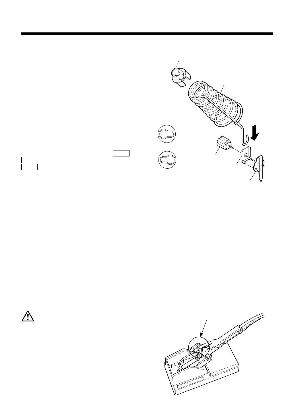
(4)Using the iron holder
Iron receptacle
Spring iron holder
OR
Mounting knob
Iron holder fitting
Cover mounting plate
●●
●Hakko 900, 902, 904
●●
When attaching soldering units other than the Hakko
926 to the Hakko 631, all you have to do is to change
the spring iron holder.
●●
●Hakko Dash and Hakko Mach
●●
Use the Hakko 631 (product number: 631-07).
●●
●Hakko 907 and 908
●●
Use the iron holder made for the Hakko 907 and 908.
Place the handpiece on the holder so that the right
side of the holder and the right side of the guide pipe
support plate are aligned as shown below. To align
with the left side, remove the guide pipe locking nut
and the joint and install the guide pipe support plate
so that it is on the left side.
I
CAUTION
Attach the iron receptacle so that the tip of the
soldering iron and the guide pipe are parallel.
●●
●Hakko 926
●●
Attach the iron holder for the Hakko 926 as shown in
the figure at the top of the next column. (In the case
of the Hakko 926, the holder can only be attached on
the left toward the front of the unit.)
5
Page 7

MAINTENANCE
CAUTION: The cutting blade is sharp. Be very careful when
handling the cutting blade.
Keep the cutting blade, driving pulley, and following pulley clean of solder
and flux using a brush or other suitable cleaning device. If the solder is not
being cut properly or the unit is generating solder balls even though the unit
is well maintained, the cutting blade may be worn. Follow the procedure
below to change the cutting blade.
Replacing the cutting blade
1. Follow steps (a) through (c) under “Changing the
solder diameter” on page 4 and remove the
following pulley assembly.
2. Use a 14-mm wrench and a pair of C-ring pliers
(or other pliers with a tip-size of about 2 mm
0.08 in.) to disassemble the following pulley
assembly.
Pliers
Turn counterclockwise
Following pulley assembly
3. Remove the cutting blade from between the top
and bottom pieces of the following pulley.
If the cutting blade is difficult to remove due to
accumulated flux and solder, push a pin downward
through the four holes on the top piece and pry the
pieces apart.
4. Clean any accumulated flux or solder off each part.
5. Assemble in the reverse order of disassembly.
Following pulley top piece
Cutting blade
Following pulley bottom piece
Wrench
Following gear
Nut
6
Page 8

OPTIONAL FEEDER PEN
Thread solder can be fed automatically by connecting the optional feeder
pen to the Hakko 374 feed controller unit. The feeder pen can be used for
the following purposes.
●The feeder pen can be used for conventional
soldering where the soldering iron is held in one
hand and the pen is held in the other to supply the
solder.
●The feeder pen can be fixed in a certain position to
supply solder to a substrate automatically.
Assembly
(1)Connecting to the main unit
Feeder pen
Feed nozzle
set screw
Feed nozzle
Part No.
C1234
C1235
B2124
Part name
Feeder Pen, for solder diameters
from 0.6 to 1.0 mm (0.02 to 0.04 in.)
Feeder Pen, for solder diameters
from 1.2 to 1.6 mm (0.05 to 0.06 in.)
Feeder Switch
(switch designed for the feeder pens)
(2)Mounting the feeder switch
(Part number: B2124)
The feeder switch is a hand-operated switch designed
especially for used with the feeder pens. Solder is fed
when the feed button is pressed.
Feed button Feeder switch
Mount so that the tip
comes to here.
Hakko 374 unit
1. Make sure the feeder pen matches the solder
diameter to be used.
2. Insert the feed nozzle into the feed nozzle
connection hole on the feed controller unit.
3. Tighten the feed nozzle set screw.
7
Feeder pen
Mini plug
Switch jack
1. Attach the feeder switch securely to the handle of
the feeder pen with adhesive tape on the back of
the feeder switch.
2. Insert the mini plug into the switch jack on the
Hakko 374 unit.
* The feeder pen can also be used with a foot-switch
instead of the feeder switch.
Page 9

OPTIONS AND REPLACEMENT PARTS
Part
No.
B1631
B1672
B2125
B1632
B1673
B2126
B1957
B1958
B2127
B2143
B2144
B2145
B1674
B1675
B1676
B1677
B2119
B1679
B1680
B1681
B1682
B2120
B1684
B1685
B1686
B1687
B2121
B1689
B1690
B1691
B1692
B2122
B1694
B1695
B1696
B1697
B2123
B2146
B2147
B2148
B2149
B2156
B2151
B2152
B2153
B2154
B2157
Part Name
Tube unit A
Tube unit B
Tube unit G
Tube unit C
Tube unit D
Tube unit H
Tube unit E
Tube unit F
Tube unit I
Tube unit J
Tube unit K
Tube unit L
Guide pipe asse’y
Guide pipe asse’y
Guide pipe asse’y
Guide pipe asse’y
Guide pipe asse’y
Guide pipe asse’y
Guide pipe asse’y
Guide pipe asse’y
Guide pipe asse’y
Guide pipe asse’y
Guide pipe asse’y
Guide pipe asse’y
Guide pipe asse’y
Guide pipe asse’y
Guide pipe asse’y
Guide pipe asse’y
Guide pipe asse’y
Guide pipe asse’y
Guide pipe asse’y
Guide pipe asse’y
Guide pipe asse’y
Guide pipe asse’y
Guide pipe asse’y
Guide pipe asse’y
Guide pipe asse’y
Guide pipe asse’y
Guide pipe asse’y
Guide pipe asse’y
Guide pipe asse’y
Guide pipe asse’y
Guide pipe asse’y
Guide pipe asse’y
Guide pipe asse’y
Guide pipe asse’y
Guide pipe asse’y
Diameter
of solder
0.6~1.0mm
(0.02~0.04 in.)
1.2mm (0.05 in.)
1.6mm (0.06 in.)
0.6~1.0mm
(0.02~0.04 in.)
1.2mm (0.05 in.)
1.6mm (0.06 in.)
0.6~1.0mm
(0.02~0.04 in.)
1.2mm (0.05 in.)
1.6mm (0.06 in.)
0.6~1.0mm
(0.02~0.04 in.)
1.2mm (0.05 in.)
1.6mm (0.06 in.)
0.6mm (0.02 in.)
0.8mm (0.03 in.)
1.0mm (0.04 in.)
1.2mm (0.05 in.)
1.6mm (0.06 in.)
0.6mm (0.02 in.)
0.8mm (0.03 in.)
1.0mm (0.04 in.)
1.2mm (0.05 in.)
1.6mm (0.06 in.)
0.6mm (0.02 in.)
0.8mm (0.03 in.)
1.0mm (0.04 in.)
1.2mm (0.05 in.)
1.6mm (0.06 in.)
0.6mm (0.02 in.)
0.8mm (0.03 in.)
1.0mm (0.04 in.)
1.2mm (0.05 in.)
1.6mm (0.06 in.)
0.6mm (0.02 in.)
0.8mm (0.03 in.)
1.0mm (0.04 in.)
1.2mm (0.05 in.)
1.6mm (0.06 in.)
0.6mm (0.02 in.)
0.8mm (0.03 in.)
1.0mm (0.04 in.)
1.2mm (0.05 in.)
1.6mm (0.06 in.)
0.6mm (0.02 in.)
0.8mm (0.03 in.)
1.0mm (0.04 in.)
1.2mm (0.05 in.)
1.6mm (0.06 in.)
Applicable
Models
900M, 900L
DASH
MACH
902, 904
907, 908
900M, N452
N453
900L, N454
920, 921, 922
918
902, 904
907
908
Part
Part Name
No.
B1699
Nozzle
B1700
Nozzle
B1701
Nozzle
B1702
Nozzle
B1703
Nozzle
B1704
Guide pipe A
B1705
Guide pipe B
B2116
Guide pipe G
B1706
Guide pipe C
B1707
Guide pipe D
B2117
Guide pipe H
B1708
Guide pipe E
B1709
Guide pipe F
B2118
Guide pipe I
B1647
Spring iron holder A
B1648
Spring iron holder B
B1649
Foot switch
B1650
Clip A / 1 pc.
B1956
Clip B / 1 pc.
B2158
Clip C / 1 pc.
631-07
Hakko 631
Iron holder
C1141
Hakko 936/937
Iron holder
C1142
Hakko 936/937
Iron holder
B1863
Mini plug
C1234
Feeder pen
C1235
Feeder pen
B2124
Feeder switch
The 900M and 900L are soldering irons used with the Hakko 926,
Hakko 927, and Hakko 928.
The 902 is a soldering iron used with the Hakko 931 and the
Hakko 932.
The 904 is a soldering iron used with the Hakko 929.
The 907 and 908 are solder irons used with the Hakko 936 and
the Hakko 937.
918, 920, 921, and 922 are product numbers from the Hakko
Mach I series. Parts that support the entire series are indicated
by MACH.
N452, N453, and N454 are product numbers from the Hakko
Dash series. Parts that support the entire series are indicated by
Dash.
The following parts may need to be changed in order to
accommodate a change in the solder diameter or type of
soldering iron used.
Driving pulley assembly
Following pulley assembly
Supply nozzle
Guide pipe assembly
Tube unit
Change these parts as necessary.
Diameter
of solder
0.6mm (0.02 in.)
0.8mm (0.03 in.)
1.0mm (0.04 in.)
1.2mm (0.05 in.)
1.6mm (0.06 in.)
0.6~1.0mm
(0.02~0.04 in.)
1.2mm (0.05 in.)
1.6mm (0.06 in.)
0.6~1.0mm
(0.02~0.04 in.)
1.2mm (0.05 in.)
1.6mm (0.06 in.)
0.6~1.0mm
(0.02~0.04 in.)
1.2mm (0.05 in.)
1.6mm (0.06 in.)
—
—
—
—
—
—
—
—
—
—
0.6~1.0mm
(0.02~0.04 in.)
1.2~1.6mm
(0.05~0.06 in.)
—
Applicable
Models
—
—
—
—
—
900M, 920
921, 922
N452, N453
907
900L, 918,
N454,
908
902, 904
926
927, 928, 929,
931, 932
—
900M, 900L,
DASH
902, 904
907, 908
DASH, MACH
900S
907, 908, 913,
914
—
—
—
—
8
Page 10
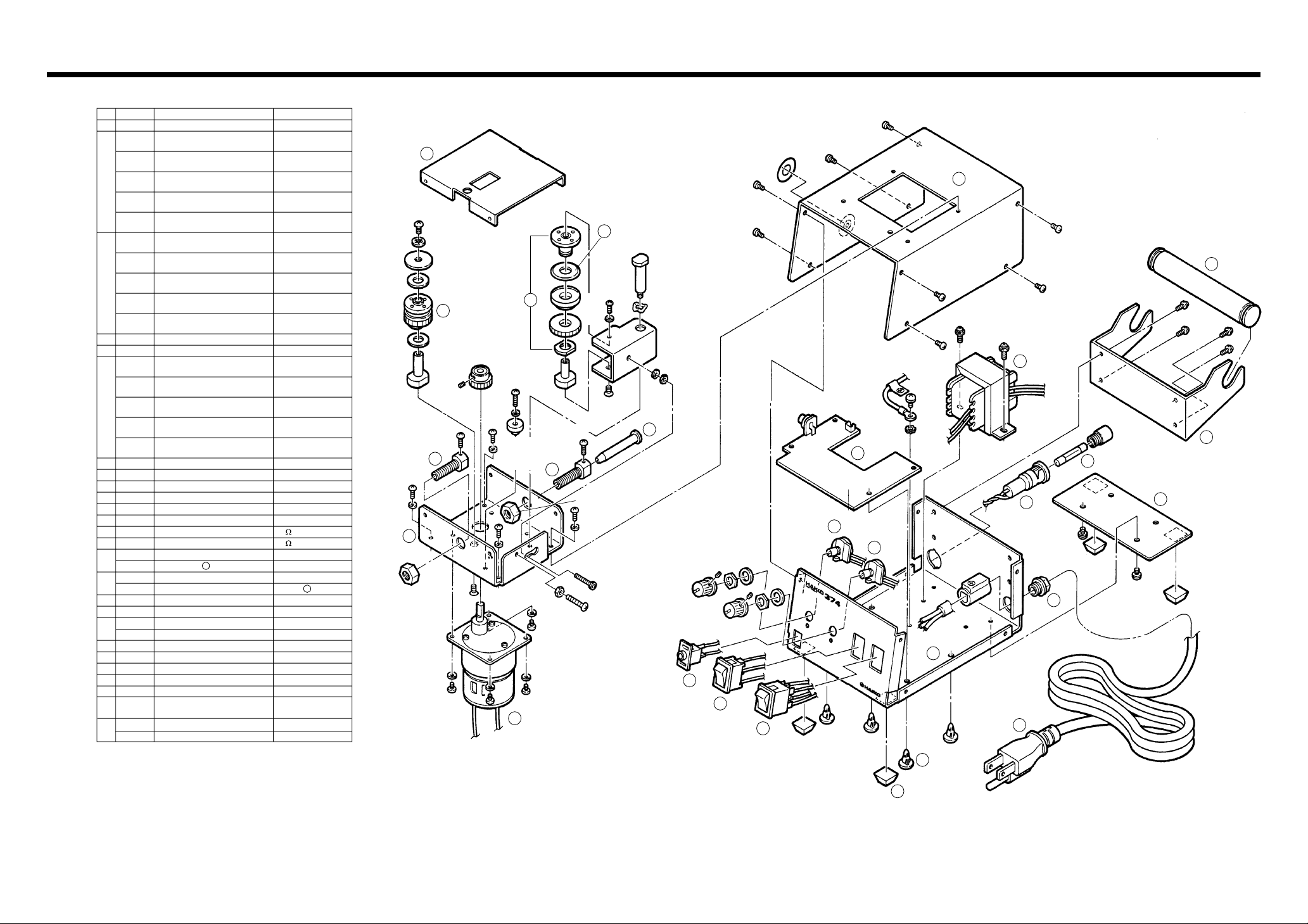
PARTS LIST
No.
1
2
3
4
5
6
7
8
9
10
11
12
13
14
15
16
17
18
19
20
21
22
23
24
25
26
Part No.
B2132
B2104
B2105
B2106
B2107
B2108
B2109
B2110
B2111
B2112
B2113
A1323
B1890
B2133
B2134
B2135
B2136
B2137
B2129
B2142
B2130
B1901
B1902
B1899
B1197
B1905
B1041
B1134
B1907
B1139
B1903
B1906
B1487
B2604
B2131
B1208
B1895
B1037
B1114
B1169
B1900
B1912
Part Name
Cover for feeding unit
Driving pulley asse’y /
for ø0.6mm (0.02 in.) solder
Driving pulley asse’y /
for ø0.8mm (0.03 in.) solder
Driving pulley asse’y /
for ø1.0mm (0.04 in.) solder
Driving pulley asse’y /
for ø1.2mm (0.05 in.) solder
Driving pulley asse’y /
for ø1.6mm (0.06 in.)solder
Following pulley asse’y /
for ø0.6mm (0.02 in.) solder
Following pulley asse’y /
for ø0.8mm (0.03 in.) solder
Following pulley asse’y /
for ø1.0mm (0.04 in.) solder
Following pulley asse’y /
for ø1.2mm (0.05 in.) solder
Following pulley asse’y /
for ø1.6mm (0.06 in.) solder
Cutting blade
Nozzle support
Supply nozzle /
for ø0.6mm (0.02 in.) solder
Supply nozzle /
for ø0.8mm (0.03 in.) solder
Supply nozzle /
for ø1.0mm (0.04 in.) solder
Supply nozzle /
for ø1.2mm (0.05 in.) solder
Supply nozzle /
for ø1.6mm (0.06 in.) solder
Motor fixing plate
Motor
Cover
Solder bobbin shaft
Solder bobbin support
P.W. B.
Potentiometer for feed speed control
Potentiometer for feed time control
Fuse holder
Fuse holder
Fuse
Fuse
Mini jack
Switch
Power switch
Power switch
Chassis
Cord stopper
Chassis support plate
Rubber stopper
Locking spacer
Power cord /
3 core & European plug
Transformer
Transformer
Description
Note: Spare or repair parts do not include mounting screws, if they are
not listed on the description. Screws must be ordered separately.
1
9
Pan head screw
M4×6
With cutting blade
With cutting blade
With cutting blade
With cutting blade
With cutting blade
With wire, connector
With potentiometer
5k
1k
S
Without fuse, 100, 110V
Without fuse, 220, 230V
125V-1A/100, 110V
S
/220, 230V
250V-1A
100 - 120V
220 - 240V
Set of 4
Set of 4
CE
100V
230V
Internal tooth
lock washer
(nominal size 4)
Nut
M8 P0.75
Hexagon
socket
set screw
M3×3
Pan head
screw
M3×6
5
7
Spring
washer
(nominal
size 3) (4)
Pan head screw
M3×4 (4)
2
3
Pan head
screw
M3×10
Spring
washer
(nominal
size 3)
Pan head
screw with washer
M3×5 (with spring
washer) (4)
Flat head screw
M4×8
5
Nut
M4 No.3
Pan head
screw
M3×6
8
4
Pan head
screw
M3×10
Spring
washer
(nominal
size 3)
Flat head screw
M4×8
Nut M8 P0.75
Hexagon socket
head cap screw
M3×15
Pan head screw
M4×16
Wave
washer
(nominal
size 8)
Nut M3
Width
across
flat 5.5
6
17
Nut P0.75 2t (2)
18
19
13
External
tooth washer
(nominal
size 4)
12
14
Pan head screw
with washer
M4×5
(with spring
washer)
20
Pan head screw
with washer
M3×6 (with spring,
plain washer) (2)
26
25
Pan head
screw
M3×4 (8)
15
Pan head screw
with washer
M4×5 (with spring
washer) (2)
21
Pan head screw with washer
M3×5 (with spring washer) (4)
16
10
11
22
23
24
109
Page 11

TROUBLESHOOTING
When the Hakko 374 fails to feed the solder properly, check the following items.
●●
●Do the parts match the solder diameter?
●●
●Is the tension adjusted properly?
●Is the tube bent or twisted?
●Have solder and flux accumulated on the
driving pulley, the following pulley, and the
cutting blade?
●Is the tension adjustment screw tight?
●Is the arm mounting screw tight?
●●
●Is the guide pipe clogged with flux?
●●
●Is the tip of the nozzle clogged with flux?
●Is the mini plug connected properly?
●Is the fuse blown?
●Is the power supply of the correct voltage and
frequency?
●Are the feed speed and the feed time appropriate?
●Is the tip temperature appropriate?
HEAD OFFICE
TEL:+81-6-6561-3225 FAX:+81-6-6561-8466
http://www.hakko.com E-mail:sales@hakko.com
OVERSEAS AFFILIATES
U.S.A.: AMERICAN HAKKO PRODUCTS, INC.
TEL: (661) 294-0090 FAX: (661) 294-0096
Toll Free (800)88-HAKKO
4 2 5 5 6
http://www.hakkousa.com
HONG KONG: HAKKO DEVELOPMENT CO., LTD.
TEL: 2811-5588 FAX: 2590-0217
http://www.hakko.com.hk
E-mail:info@hakko.com.hk
SINGAPORE: HAKKO PRODUCTS PTE., LTD.
TEL: 6748-2277 FAX: 6744-0033
http://www.hakko.com.sg
E-mail:sales@hakko.com.sg
Please access to the following address for the other Sales affiliates.
http://www.hakko.com/address
11
MA00519JB030422
Apr.2003
 Loading...