

Page 1
SELF FEEDER
Thank you for purchasing the HAKKO 373 Self Feeder.
Please read this manual carefully before operating the
HAKKO 373. Store the manual in a safe, easily
accessible place for future reference.
CAUTION: You must install the Solder Dia. Adjustment Ring before use.
TABLE OF CONTENTS
Precautions.................................................................1
Specifications..............................................................1
Names of Parts ...........................................................2
Setting Up the HAKKO 373 ........................................3
Operation ....................................................................6
Replacement of Parts .................................................8
Options & Replacement Parts ....................................9
Parts List................................................................... 11
Troubleshooting Guide..............................................13
Page 2
Precautions
CAUTION
· Setting up should be done while the soldering iron is cool, or you may get burnt.
·Do not force the guide pipe bend or turn as this may result in damage.
·Do not operate with tube bending or holding in sharp angle. It may cause to clogging.
·Input of switching is no-voltage input. Do not apply voltage to the jack for switch.
·Periodically, remove the guide pipe and clean out clogged flux.
·Do not force the adjustment screw to adjust the amount of solder return. It may cause to damage.
·If the power cord is damaged, it must be replaced by the manufacturer, its service agent or
similarly qualified person in order to avoid personal injury or damage to the unit.
Specifications
·Usable Solder
Usable solders are as follows. Some of the parts should be changed according to the diameter of
solder desired to use.
Dia. of
solder
Maximum quantity of usable solder is 1 kg (2.2 pounds).
(mm)
(inch)
0.6, 0.65, 0.8, 1.0, 1.2, 1.6
0.024, 0.025, 0.031, 0.039, 0.047, 0.063
·Usable Soldering Iron
Soldering Iron
HAKKO 900M (For HAKKO 926, 927, 928)
HAKKO 900L (For HAKKO 926, 927, 928)
HAKKO 902 (For HAKKO 931)
HAKKO 903 (For HAKKO 939)
HAKKO 904 (For HAKKO 929)
HAKKO DASH
HAKKO MACH-I
HAKKO 907 (For HAKKO 936, 937)
HAKKO 908 (For HAKKO 936, 937)
Operationable only with Foot Switch
·Specifications
Power Consumption
Motor Rate
Solder Feed Time
Solder Feed Speed
Solder Feed Quantity
Solder Return Quantity
Outer Dimensions
Weight
6 W
DC 24 V 3.2W
0~7 sec.
4.5~26 mm (0.14~1 in.)/sec.
0~182 mm (0~7.2 in.)
0~5 mm (0~0.2 in.) (Fixed Speed)
107(W) x 110(H) x 215(D)
Approx.1.5 kg/3.3 pounds
Remarks
1
Page 3
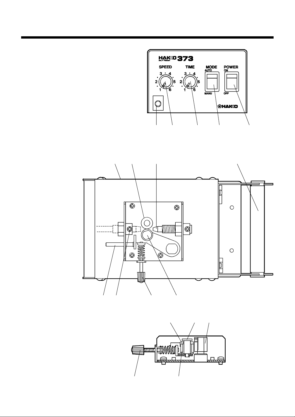
Names of Parts
1.Jack for Switch
2. Feed Speed Control Knob
3.Feed Time Control Knob
4.Mode Switch
5.Power Switch
6.Release Lever
7.Securing Screw
8.Tension Adjustment Knob
9.Tension Gear Guide Shaft
10.Adjustment for the amount of solder return
11.Feed Gear
12.Supply Nozzle
13.Solder Bobbin Shaft
10 1 1 12 13
12 3 4 5
14.Solder Dia. Adjustment Ring
15.T ension Gear
8
976
14 9 11
8
15
2
Page 4
Setting Up the HAKKO 373
·Setting up should be done while the soldering iron is cool, or you may get burnt.
·Do not force the guide pipe bend or turn as this may result in damage.
·Do not operate with tube bending or holding in sharp angle. It may cause to clogging.
1. Install the Solder Dia.
Adjustment Ring
2. Setting the Guide Pipe
Asse’y
1. Remove the tension gear guide shaft.
2. Attach the solder dia. adjustment ring according to the
diameter of your desired solder and attach the tension
gear guide shaft.
Tension Gear Guide Shaft
Tension Gear
Solder Dia.
Adjustment Ring
Set the guide pipe asse’y between the nipple (or nut) and
handle, and secure it. Washer may need depend on the type
of iron. Please refer to the following figure.
HAKKO 900, HAKKO DASH & 907, 908
Guide Pipe Asse’y
Nut
HAKKO 902, 903, 904
Nipple Wave Washer
HAKKO MACH-I
Ring Washer
Nut
3
Handle
Guide Pipe Asse’y
Handle
Guide Pipe Asse’y
Handle
Page 5
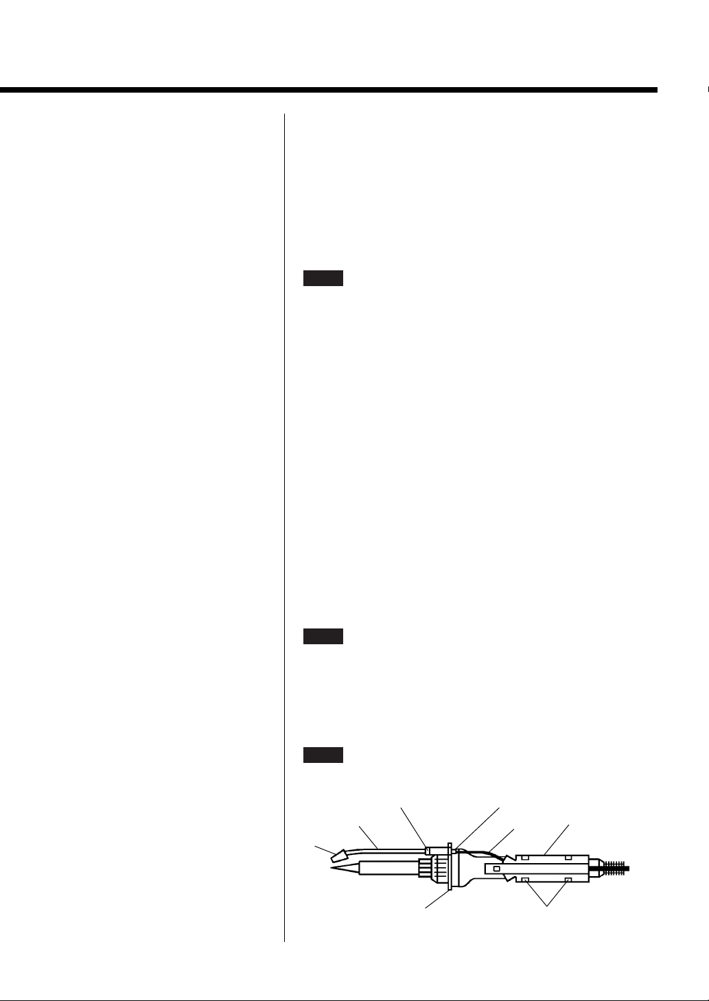
3. Setting the Tube Unit
Setting Up the HAKKO 373
(a)Attach the Tube to Guide
Pipe Asse’y .
(b)Set the Attachment on the
Handle of Soldering Iron.
The tube is double structure. Insert the inside tube into the
hole of the connection, and the outside black tube should
fully cover the screw part of the connection. Be sure that
not to bend the tube.
NOTE
The Att achment is not necessary if you use HAKKO MACHI.
i. Position the attachment on the handle of iron. Decide
which outlet of attachment should use for the tube as the
tube can be pulled out from either way of the attachment.
Find the best position where can connect the tube straight
to the pipe. Be careful not to damage the inner wiring if
replace the tube inside of the attachment.
ii. Secure the attachment. Set the attachment on the handle
securely with clips and adhesive tape on backside of the
attachment. Refer to the following figure on the setting
position of the attachment and the guide pipe. Pay
attention on the setting angle of the guide pipe and the
attachment.
4. Connect the Feeding
Nozzle
Insert the feeding nozzle into the feeding unit on the top of
the station, and secure it with screw.
NOTE
Securing the screw excessively may break the feeding
nozzle.
5. Connect the Mini-plug Insert the mini-plug branching from the tube unit into the
jack of the station.
NOTE
Nozzle
Connect the mini-plug of foot switch to the station if you
use HAKKO MACH-I.
Securing Nut for Guide Pipe Connection
Guide Pipe
Tube
Attachment
ClipsGuide Pipe Holder
4
Page 6

Setting Up the HAKKO 373
6. Setting the Solder Set a new solder after pull the old solder out when the old
one left in tube.
(a)Remove the tension gear guide shaft. And attach the
solder dia. adjustment ring according to the diameter of
your desired solder.
(b)Insert the solder bobbin shaft in the solder bobbin and
mount it on rear of the station. Solder should be fed over
the bobbin as the following figure.
(c) Insert the solder from the supply nozzle.
(d)With pressing release lever, put the inserted solder of
approx. 10 mm/0.4 in. into the feeding nozzle through
between tension gears.
MANUAL
.
7. Changing the Solder
Diameter
(e)Power switch on, and set MODE to
(f) Press the trigger switch, and feed the solder.
Replace the solder dia. adjustment ring, when using the
soldering iron continuously but desire to change the
diameter of solder. The guide pipe asse’y should change
according to the diameter of solder. Refer to the section
“Replacement of Parts”.
(a)Power switch off. Open the release lever and roll back
the left solder to the bobbin.
(b)Remove the tension gear guide shaft, and replace the
solder dia. adjustment ring according to desired solder
dia. Remove the tension gear guide shaft turning with a
spanner or pliers.
(c) Replace the guide pipe asse’y if it’s necessary.
8. Use in Vertical Vertical use is available. Fixing in vertical is as following
figure.
46mm
2-ƒÓ4.2
5
Page 7

Operation
Solder will be fed by pressing the feed switch (or foot switch).
·MODE ·AUTO MODE
If you press the feed switch, solder will be fed with set time
and speed independently of length of pressing time.
·MANUAL MODE
Solder will be fed with set speed during pressing the feed
switch.
·Setting for Feeding
Time and Speed
·Adjustment for the
Amount of Solder
Return
Set the speed before the time. For the setting speed, both
AUTO
for setting time.
After feed solder, specific length of solder can be returned.
This solder return function permits use for simple robots.
Amount of solder return is adjustable within 0~13 mm
(0~0.51 in.). Solder should be rolled back if the amount of
solder return is bigger than the amount of solder feed. Please
set the amount of solder return as small as possible. If the
tip of the returning solder reaches to the guide pipe, flux
will easily accumulate at this point. Be sure that it will not
happen.
Insert a driver into a adjustment hall on the side of the
station. Turn lef t for smaller and turn right for bigger amount.
MANUAL
&
are effective, but only
AUTO
is effective
·Adjustment of Tension When adjust the tension, be sure that not the gear to be
slipped during feed solder, or do not force to feed solder
slipping gear when solder clog.
Set the tension gear loosely for fine solder (ƒÓ0.6mm,
0.8mm/0.024 in., 0.031 in.). Refer to the following chart.
Solder Dia. ø0.6mm
maximum
6
ø1.0mm
14mm
ø1.6mm
10mm
Page 8

Operation
·Usage of Iron Holder
• HAKKO 926
If you use HAKKO 926, refer to the following figure to set
the iron holder. (As for the HAKKO 926, the setting is
available only on it’s left.)
Iron Receptacle
Spring Iron Holder
or
Thumb screw
Holder Mounting Base
Set the iron receptacle in the spring iron holder keeping the
iron tip and the guide pipe horizontally.
• HAKKO 631 Simply replace the iron holder if you use with iron holder
HAKKO 631 for except HAKKO 926.
• HAKKO 907, 908 Place the soldering iron in the iron holder so that the right
side of the guide pipe holder fits to the right side of the iron
receptacle.
When you want to fit it to the left side of the iron receptacle,
remove the securing nut for the guide pipe and the
connection; then reattach them in the opposite side.
7
Page 9

Replacement of Parts
1. When you change the
Solder Diameter
Changing matter
From the range of 0.6~1.0mm to the range of 0.6~1.0mm
From the range of 1.2~1.6mm to the range of 1.2~1.6mm
From the range of 0.6~1.0mm to the range of 1.2~1.6mm
From the range of 1.2~1.6mm to the range of 0.6~1.0mm
2. When you change the
Soldering Iron
Please replace the parts indicated on the following chart when
you change solder diameter.
Please replace the tube unit and guide pipe asse’y, when
you change the soldering iron. It is not necessary to replace
the parts if the items are in the same frame in the following
chart. Foot switch is necessary if you use the HAKKO
MACH-I.
Tube Unit
Guide Pipe Asse’y
900M, 900L, N452, N453, N454 902, 903, 904
N452, N453, 900M N454, 900L 920, 921, 922 918
Solder Dia.
Adjustment Ring
replace
replace
replace
replace
Nozzle
replace
replace
replace
replace
918, 920, 921, 922 907, 908
902, 903, 904
Guide
Pipe
same
same
replace
replace
Tube
Unit
same
same
replace
replace
907 908
8
Page 10

Options & Replacement Parts
Part No.
B1626
B1627
B1628
B1629
B1630
B1631
B1672
B1632
B1673
B1957
B1958
B2143
B2144
B1674
B1675
B1676
B1677
B1678
B1679
B1680
B1681
B1682
B1683
B1684
B1685
B1686
B1687
B1688
B1689
B1690
B1691
B1692
B1693
Part Name
Solder Dia. Adjustment Ring
Solder Dia. Adjustment Ring
Solder Dia. Adjustment Ring
Solder Dia. Adjustment Ring
Solder Dia. Adjustment Ring
Tube Unit A/with Switch
Tube Unit B/with Switch
Tube Unit C
Tube Unit D
Tube Unit E/with Switch
Tube Unit F/with Switch
Tube Unit J/with Switch
Tube Unit K/with Switch
Guide Pipe Asse’y
Guide Pipe Asse’y
Guide Pipe Asse’y
Guide Pipe Asse’y
Guide Pipe Asse’y
Guide Pipe Asse’y
Guide Pipe Asse’y
Guide Pipe Asse’y
Guide Pipe Asse’y
Guide Pipe Asse’y
Guide Pipe Asse’y
Guide Pipe Asse’y
Guide Pipe Asse’y
Guide Pipe Asse’y
Guide Pipe Asse’y
Guide Pipe Asse’y
Guide Pipe Asse’y
Guide Pipe Asse’y
Guide Pipe Asse’y
Guide Pipe Asse’y
Dia. of Solder
0.6, 0.65mm
0.8mm
1.0mm
1.2mm
1.6mm
0.6~1.0mm
1.2~1.6mm
0.6~1.0mm
1.2~1.6mm
0.6~1.0mm
1.2~1.6mm
0.6~1.0mm
1.2~1.6mm
0.6, 0.65mm
0.8mm
1.0mm
1.2mm
1.6mm
0.6, 0.65mm
0.8mm
1.0mm
1.2mm
1.6mm
0.6, 0.65mm
0.8mm
1.0mm
1.2mm
1.6mm
0.6, 0.65mm
0.8mm
1.0mm
1.2mm
1.6mm
Soldering Iron
-
-
-
-
900M, 900L, DASH
MACH-I
902, 903, 904
907, 908
900M, N452, N453
900L, N454
920, 921, 922
918
9
Page 11

Options & Replacement Parts
Part No.
B1694
B1695
B1696
B1697
B1698
B2146
B2147
B2148
B2149
B2150
B2151
B2152
B2153
B2154
B2155
B1699
B1700
B1701
B1702
B1703
B1704
B1705
B1706
B1707
B1708
B1709
B1647
B1648
B1649
B1650
B1956
B2158
631-07
·900M, 900L are Iron Parts for HAKKO 926, 927, 928.
·902 is Iron Part for HAKKO 931.
·903 is Iron Part for HAKKO 929 (120V), 939.
·904 is Iron Part for HAKKO 929 (100, 110, 220, 230, 240V).
·918, 920, 921, 922 are Parts No. of HAKKO MACH-I series. MACH-I means applicable for all items of HAKKO MACH-I series.
·N452, N453, N454 are Parts No. of HAKKO DASH series. DASH means applicable for all items of HAKKO DASH series.
·907, 908 are Iron Parts for HAKKO 936, 937.
Guide Pipe Asse’y
Guide Pipe Asse’y
Guide Pipe Asse’y
Guide Pipe Asse’y
Guide Pipe Asse’y
Guide Pipe Asse’y
Guide Pipe Asse’y
Guide Pipe Asse’y
Guide Pipe Asse’y
Guide Pipe Asse’y
Guide Pipe Asse’y
Guide Pipe Asse’y
Guide Pipe Asse’y
Guide Pipe Asse’y
Guide Pipe Asse’y
Nozzle
Nozzle
Nozzle
Nozzle
Nozzle
Guide Pipe A
Guide Pipe B
Guide Pipe C
Guide Pipe D
Guide Pipe E
Guide Pipe F
Spring Iron Holder A
Spring Iron Holder B
Foot Switch
Clip A/1 pc
Clip B/1 pc
Clip C/1 pc
HAKKO631 Iron Holder
Part Name
Dia. of Solder
0.6, 0.65mm
0.8mm
1.0mm
1.2mm
1.6mm
0.6, 0.65mm
0.8mm
1.0mm
1.2mm
1.6mm
0.6, 0.65mm
0.8mm
1.0mm
1.2mm
1.6mm
0.6, 0.65mm
0.8mm
1.0mm
1.2mm
1.6mm
0.6~1.0mm
1.2~1.6mm
0.6~1.0mm
1.2~1.6mm
0.6~1.0mm
1.2~1.6mm
-
-
-
-
-
-
-
Soldering Iron
902, 903, 904
907
908
-
-
-
-
900M, 920, 921, 922
N452, N453, 907
900L, 918, N454,
908
902, 903, 904
926
927, 928, 929, 931
900M, 900L, DASH
902, 903, 904
907, 908
DASH, MACH-I
10
Page 12

Parts List
Parts List
Part No.
Item No.
1
2
3
4
5
6
7
8
9
10
11
12
13
14
15
16
17
18
19
20
21
22
23
24
25
26
27
28
29
30
31
32
33
34
35
36
37
Part Name Description
B1897 Cover for Feeding Unit
B1882 Tension Gear Guide Shaft
B1626 Solder Dia. Adjustment Ring for 0.6, 0.65mm
B1627 Solder Dia. Adjustment Ring for 0.8mm
B1628 Solder Dia. Adjustment Ring for 1.0mm
B1629 Solder Dia. Adjustment Ring for 1.2mm
B1630 Solder Dia. Adjustment Ring for 1.6mm
B1885 Tension Gear
B1886 Tension Lever Fixing Shaft
B1908 Washer for Wave Washer
B1894 Tension Lever w/Screw
B1883 Tension Spring
B1881 Feed Gear w/Screw
B1887 Washer for Tension Lever Fixing Guide
B1888 Tension Lever Fixing Guide
B1889 Tension Lever Fixing Washer
B1890 Nozzle Support w/Nut, Screw
B1892 Supply Nozzle
B1891 Motor Fixing Plate
B1893 Release Lever w/Washer
B1884 Tension Adjustment Knob w/Nuts
B1880 Motor
B1898 Cover
B1900 Transformer 100V–24V
B1909 Transformer 110V–24V
B1910 Transformer 120V–24V
B1911 Transformer 220, 230V–24V
B1912 Transformer 240V–24V
B1901 Solder Bobbin Shaft
B1902 Solder Bobbin Support
B1899 P.W.B. w/Potentiometers
B1041 Fuse Holder w/o Fuse
B1134 Fuse Holder (S) w/o Fuse
B1907 Fuse 125V–1A/100,110,120V
B1138 Fuse 250V–1A/220,230,240V
B1139 Fuse 250V–1A S /220,230V
B1895 Chassis Support Plate w/Rubber Stoppers
B1904 Knob
B1903 Mini Jack
B1906 Switch
B1487 Power Switch
B1197 Potentiometer for Feed Speed Control 5K , w/Nut
B1905 Potentiometer for Feed Time Control 1M , w/Nut
B1896 Chassis w/Rubber Stoppers
B1037 Rubber Stopper Set of 4
B1114 Locking Spacer Set of 4
B1208 Cord Stopper
B1163 Power Cord 3 Core & American Plug, 100V
B1007 Power Cord 3 Core But No Plug
B1168 Power Cord 3 Core & American Plug
B1169 Power Cord 3 Core & European Plug
B1214 Power Cord 3 Core & Australian Plug
B1964 Power Cord 3 Core & BS Plug
B2087 Power Cord 3 Wire & BS Plug (CE)
1
Hexagon
Socket Set Screw
M 3 x 3
Pan Head Screw
M 3 x 6
Pan Head Screw
with Washer
M 3 x 5(4)
15
Nut
M 8 P0.75
16
Plain Washer
nominal size 3
Pan Head Screw
with Washer
M 3 x 5(4)
13
9
18
2
3
4
Pan Head Screw
M 3 x 3
Pan Head
Screw
M 3 x 6
10
13
Nut
M 8 P0.75
17
5
6
Wave Washer
nominal size WW–10
7
Push Type
8
Lock Nut
nominal size 3
11
Nut M 3(2)
12
14
Note: Spare or repair parts do not include mounting screws, if they are not listed on the description.
Screws must be ordered separately.
19
Pan Head Screw
M 3 x 4(8)
21
22
Nut
M 7 P0.75 2t (2)
27
27
28
29
30
23
External Tooth
Lock Washer
nominal size 4
31
Pan Head Screw
with Washer M 4 x 5
32
35
34
Pan Head Screw
with Washer (w/Spring, Plain Washer)
M 3 x 6(2)
20
25
24
36
33
37
Pan Head Screw
with Washer
M 3 x 5(4)
26
Pan Head
Screw
with Washer
M 4 x 5(2)
11
12
Page 13

Troubleshooting Guide
If the solder can not be fed smoothly, please check following points.
·Are you using proper parts according to the diameter of solder?
·Did you adjust the tension properly?
·Isn’t the tube bent or transformed?
·Isn’t solder adhered at the feed gear or the tension gear?
·Isn’t the nozzle clogged with flux?
·Is the mini-plug correctly connected?
·Isn’t the fuse blown?
·Is the power cord correctly connected?
13
Page 14

September 1998
 Loading...