

Haier MVAH048MV2AA, MVAH042MV2AA, MVAH036MV2AA, MVAH030MV2AA, MVAH024MV2AA Owner’s Manual
...Page 1

Indoor Unit Operation & Installation Manual
MVAH009MV2AA
MVAH012MV2AA
MVAH018MV2AA
MVAH024MV2AA
MVAH030MV2AA
MVAH036MV2AA
MVAH042MV2AA
MVAH048MV2AA
Please read this manual carefully before using
Keep this operation manual for future reference
Original instructions
Page 2
User Manual
Contents
Parts and Functions
Safety
Maintenance
Fault Checkup
Installation Procedures
Electrical Wiring
Test Run & Fault Code
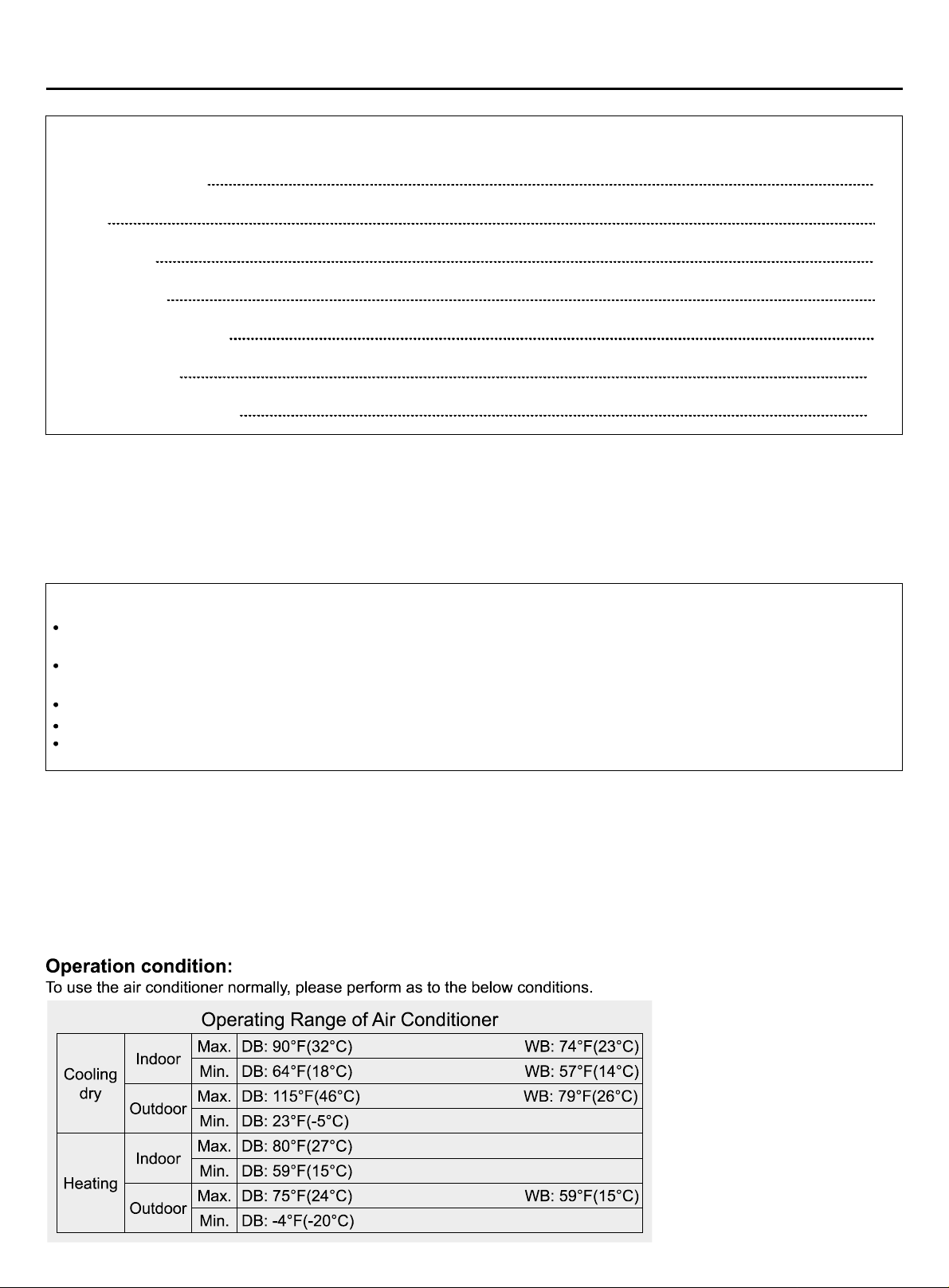
Your air conditioner may be subject to any change owing to the improvement of Haier products.
MRV series multi zone air conditioning systems can operate multiple indoor units in heating or cooling. When in cooling,
only units set to cool will run. Same logic applies for heating..
Turn power on for 12 hours prior to start-up to allow the crankcase heater adequate time to protect the compressor. All
indoor units on the same refrigeration system should use the unified power switch to
ensure that all indoor units are all powered on during system operation.
13
19
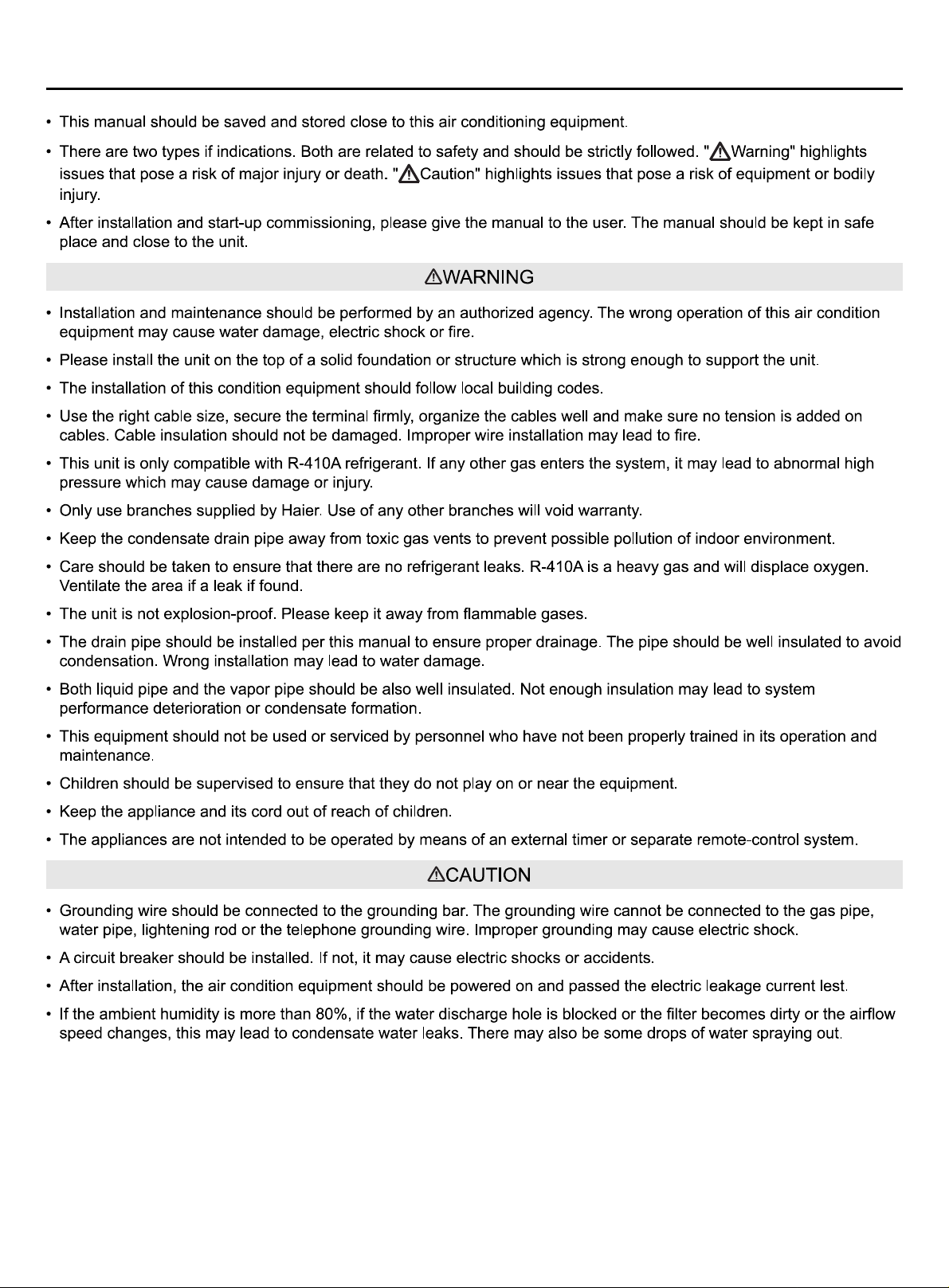
Warning
If the supply cord is damaged, it must be replaced by the manufacturer, its service agent or similarly qualified persons
in order to avoid a hazard.
This equipment should not be used or serviced by personnel who have not been properly trained in its operation and
maintenance.
Children should be supervised to ensure that they do not play with the appliance.
The appliances are not intended to be operated by means of an external timer or separate remote-control system.
Keep the appliance and its cord out of reach of children less than 8 years.
1
2
4
5
6
Product Features
1.Function of central control (optional from our company);
2.Automatic display of fault detection;
3.The air conditioner is provided with the function fo compensation for power supply.During operation,when the power supply
fails emergently and resumes again,the air conditioner returns to the working condition before power failure,if provided
with compensation function.
4.Now this indoor unit only has wired controller function,the indoor unit that has remote controller function need to set in
factory especially.
Page 3
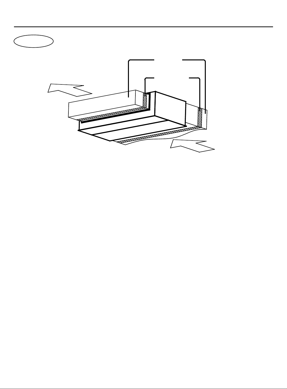
Parts and Functions
indoor unit
air duct
air outlet port
soft connection
air inlet port
1
Page 4
Safety
2
Page 5
Safety
3
Page 6
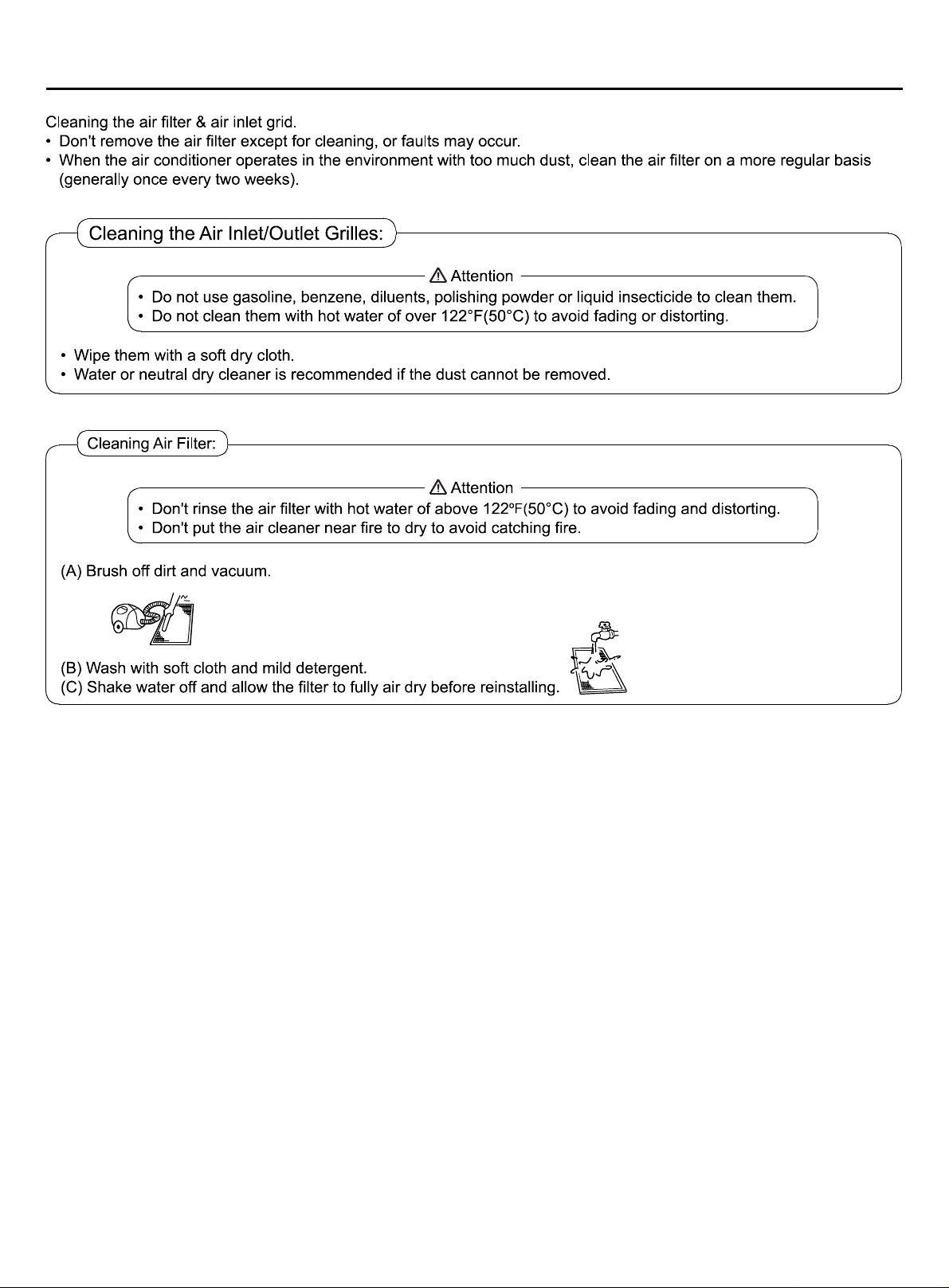
Maintenance
4
Page 7

Fault Checkup
5
Page 8
Installation Procedures
This manual cannot completely illustrate all the properties of the products you bought. Please contact the local Haier
distribution center if you have any question or request.
1. Before installation [Don’t throw away the attached parts required for the installation]
Determine the route to move the unit to the installation site;
Transport the unit in it's box to prevent damage.
2. Select the installation site
(1) The installation site should be selected according the following
conditions, which should be approved by users.
where an ideal air distribution can be ensured;
where there is no blockage in the air passage;
where the condensed water can be drained out properly;
where the structure can bear the weight of the indoor unit;
where enough space can be ensured for maintenance.
where the lengths of the piping between indoor units and
outdoor units are within the allowable range (refer to Installation
of Outdoor Units)
where the distance of at least 3.28ft (1m) between indoor
units, outdoor units, mains supply, connecting wires and television
or radio should be kept as to avoid the image disturbance and
noises of the above electrical appliances. (Even if 3.28ft (1m) can
be ensured, noise might occur if there is strong electric wave.)
Additionally, equipments, television or other valuables can’t be
put under the unit as to avoid the condensed water of the unit
from dropping into the above articles, causing damaging.
(2) Height of Ceiling:
The ceiling should be located at the place, where the
central position of air outlet port is less than 9.84ft (3m) high
above the ground.
(3) Hoisting studs should be used during installation.
Check if the location can bear the weight of the unit.
Reinforce it before installation if necessary.
(4)The dimension of maintenance
Make sure that it is easy to demount the electrical control
box, fan, montor, filter.
Required Tools for Installation
Brazing torch
15% silver phosphorous copper brazing alloy
Wire stripper
Soap-and-water solution or gas leakage detector
Torque wrench
17mm, 22mm, 26mm
Tubing cutter
Reaming tool
Flaring tool
Razor knife
Measuring tape
Level
Vacuum pump
Micron gauge
Nitrogen
Mini-Split AD-87 Adapter (1/4* to 5/16*)
Non-adhesive Tape
Adhesive Tape
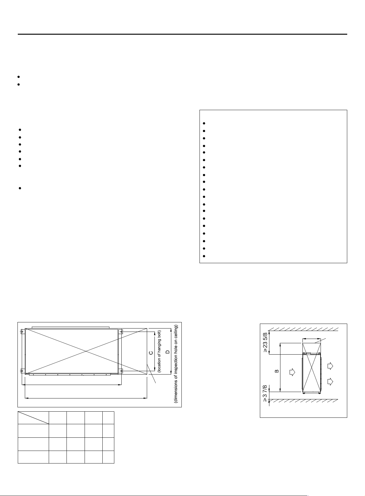
Electrical wiring
(dimensions of inspection hole on ceiling)
Size
Model
MVAH009-
018MV2AA
MVAH024-
030MV2AA
MVAH036-
048MV2AA
A
(location of hanging bolt)
B
C
B
A
(in)
(in)
31
43 1/4
18 5/8
38 7/8
51 1/8
18 5/82525
55 1/467 3/420 7/829
(in)
(in)
D
checking
port
barrier
D
space needed for installation (unit:in)
checking
port
6
Page 9

Installation Procedures
3. Preparation before Installation
(1) Unit height is 11 inches
H
C
top
E
C
A
Size
Model
MVAH009-
018MV2AA
MVAH024-
030MV2AA
MVAH036-
048MV2AA
(in)
31
18 5/8
38 7/8
18 5/8
55 1/420 7/8
(in)
(in)
29 1/2
29 1/2
53 7/8
(2) If necessary, make a hole for installation and inspection on the ceiling. (used for the situation with a ceiling)
For the size of the inspection hole on the ceiling, please refer to the above drawing.
Before installation, finish all the preparations for all piping connected to indoor units (refrigerant, water drainage) and
wiring (connection line of the line control, connection line between indoor units and outdoor unit) so that they can be
connected with indoor units right after installation.
For the inspection hole, the ceiling might be reinforced to keep the evenness of the ceiling and avoid the vibration of the
ceiling. For details, please consult the construction contractor.
H
(in)
27 3/8
27 3/8
31 3/8
(3) Install the 3/8"(M10) hanging bolts
In order to support the weight of the unit, use barb bolts in the situation with a ceiling.
notch grapping
notch plug
In the situation with the new ceiling, use inlaid bolts, embedded bolts or other parts
provided on site. Before proceeding the installation, adjust the gap between the bolt
and the ceiling.
(4) Installation of Indoor Units
Fix the indoor unit with the hoisting stud.
3/8" nut
hanging bolt
3/8"(M10) shim
3/8"(M10) hanging bolts
If necessary, the machine can be hanged
on the beam with bolts instead of the
main unit
3/8" washer
hoisting stud.
Note:
When the sizes of the main unit don’t match the hole on the ceiling, regulate the slot on the hanging bracket.
Adjusting the level
Adjust the level with a level meter or according to the following ways:
Make the adjustment as shown in the figure.
plug
concrete
Static Pressure Range
unit: IWC
Static Pressure Range
0~0.8
7
Page 10

Installation Procedures
4. Drainpipes
MVAH009-030MV2AA
MVAH036-048MV2AA
drain pipe
gas pipe
1 1/8
20 1/8
18 5/8
liquid pipe
18 3/8
29
unit: in
16 1/4
1 1/8
18 3/8
16
18 3/8
(a) To prevent water flowing back into air conditioner when the unit stops running, drain hose should decline to the drainage
side with an inclination of above 1/100. Drain hose expansion or water accumulation should be prevented, or else it will
cause abnormal noise.
Proper Piping
hanging bolt
heat insultor
39 3/8~78 6/8in
gradient of 1/100 or over
Improper Piping
air outlet port
avoid lobing
avoid curving
don't put pipe
into water
(b) Please use the accessory drain hose to connect indoor unit's water outlet and PVC pipe. Use snap rings to tighten
them as shown in the following figure:
main unit
wash port
wash port
sealing washer [for insulation]
(accessory)
drainage hose
joint (purchased at local shop)
drainage hose
thread clip
(accessory)
sealing washer [for insulation](accessory)
binding
8
hard PVC tube (purchased at local shop)
sealing washer [for insulation](accessory)
Page 11

Installation Procedures
(c) Please use rigid PVC adhesive for connection of other pipes and ensure there
is no leakage.
ensure the biggest height difference
(about 3 7/8in)
(d) Drain hose must be wrapped with insulation sleeve and tightened with a strap to
prevent air leakage from producing condensate.
(e) When connecting the drain hose, do not pull on it to avoid the pipe connections
from getting loose or disconnected. Drain hose should not be pulled out laterally for
gradient of 1/100 or over
more than 8in(200mm) and should be supported every 31-39in(0.8- 1.0m) to avoid bending.
(f) The end of drain hose should be more than 2in(50mm) away from the ground or the bottom of drainage tank. It should
not be put in water. To directly drain condensate into drainage ditch, the drain hose must be U-shaped to avoid smell from
entering through the hose into room.
Testing Drainage System
Before the test, ensure the drain hose is clear and all connections are tightly sealed.
Then perform the drainage test as follows:
1. Add about 0.132gal (500ml) of water into the water pan through water injection hole.
2. Switch on the power and operate the unit in cooling mode. Check that the water outlet drains water normally and that
there are no leakages at the connections. After the drainage test is complete, replace the water injection hole plug.
3. In the condition of new house, test the drainage system before fitting up the ceiling.
4. Even if it is installed in the season needed to heating, the testing should also be performed.
5. Installation of Air Return & Air Exhaust Pipes
For the choice and installation of air return port, air return pipe, air exhaust port and exhaust pipe, please consult service
personnel of Haier company. Calculate the design chart and exterior static pressure, and select the exhaust pipe with
appropriate length and shapes.
main unit of air
conditioner
ceiling
suface
special exhaust
port (purchased at
local shop)
exhaust pipe
(purchased
at local
shop)
access panel
air return
pipe
(purchase
d at local
shop)
special air return
pipe (purchased at
local shop) with air
cleaner
The length difference between pipes should be limited to be less than 2:1;
Make the piping as short as possible;
Keep the min. elbow quantity;
Wind the heat insulating material around the flange between the main unit and the exhaust
pipe for heat insulation and sealing. Install the piping before fitting up the ceiling.
At least 6.6 feet air duct is needed at air inlet and air outlet.
Flexible connection is needed between indoor units and air duct.
ESP should be lower than 0.8 IWC.
6. Cautions in Installation of Air Return Duct & Exhaust Duct
It is recommended to use ducting, which can be
anti-condensation and absorb sound. (purchased at local shops)
Heat insulation should be made for the ducting.
The special exhaust port should be arranged at the place where the air is distributed evenly.
An access panel should be added to the ceiling below the indoor unit for serviceability.
special exhaust port
positioning with bolt
supply
duct
air
air
9
Page 12

Installation Procedures
7.Connection of return air duct (setting back air return opening when leaving factory)
Remarks:
This series of air conditioners can be arranged in two air return modes: 1. Air return from the back (Factory default); 2. Air
return from the bottom (can be adjusted on site. See the following figures.)
Note:
The downward air return mode will increase noise 3-5dB(A). It is recommended to install the air conditioner in downward
return air mode 2 if enough space is available.
F
8. Adding fresh air intake duct
(1) Cut away the circular opening on the side of the return
end
Model
Size
MVAH009~018MV2AA
MVAH024-030MV2AA
MVAH036-048MV2AA 50 3/8 9 2/8
(2) Install round duct collar (obtained locally)
F
(in)
26
29 1/8
below air return openingback air return opening
G
(in)
7 7/8
7 7/8
cut away
cut away
(3) Use foil tape to prevent air leaks
Duct collar
10
Page 13

Installation Procedures
9.Install outlet flange
Install outlet flange basising the needs, the outlet flange is standard component, bolts are laied in accessories box.
ceiling
Note:
You can select not to connect with the flange. Instead of it, you can use the round plastic air outlet (purchased by user)
10. Examples for Bad Installation
The unit is not equipped with the air return pipe and the inner side of the suspending ceiling is used as the blast pipe,
causing the humidity increasing due to irregular air mass, strong wind or sunlight from the outside world.
There might be condensate dropping down at the outer side of the blast pipe. The humidity is high, even if the inner side
of the suspended ceiling isn’t used as a blast pipe in new concrete buildings. At this time, the whole body should use the
thermo wool for heat preservation (the thermo wool can be packed with a steel wire).
It is operated under the conditions beyond the limits, leading to the overload of the compressor.
Affected by the capacity of the exhaust fan, and the strong wind and wind direction in the outer flue, when the blowing
quantity of the air conditioner exceeds the limits, the drained water of the heat exchanger will overflow, causing water
leakage.
exhaust fan
example of bad installation
11. Static Pressure GradeSetting
For MVAH036~048MV2AA units, after installation need to preliminary estimates external static pressure, according to the
external static pressuresetting the unit's static pressure grade by controller.
Note: The detail operation methods for setting the unit's static pressure grade refer to the controller manual.
The static pressure range of each gradeas follows:
Grade Grade/Static Pressure Range (IWC)
1 0~0.1
2 0.1~0.3
3 0.3~0.5
4 0.5~0.7
5 0.7~0.8
11
Page 14

Installation Procedures
12. Refrigerant Tube
Pipe Length & Height Difference
Please refer to the attached manual of outdoor units.
Piping Materials & Heat Insulating Materials
As to prevent condensation, heat insulating treatment
should be performed. The heat insulating treatment
for gas and liquid piping should be done respectively.
Tubing Materials & Specifications
Piping Material
Heat Insulating Material
Hard PVC tube VP 1in (inner bore)
Vesicant polythene thickness: over 1/4in
Model
Tubing Size
Tubing Material
Gas pipe
Liquid pipe
MVAH009~018MV2AA
1/2
1/4
Seamless copper pipe rated for R410A refrigerant
MVAH024~048MV2AA
5/8
3/8
Refrigerant Recharge Amount
Add the refrigerant according to the installation instruction of outdoor unit. The addition of R410A refrigerant must be
performed with a digital scale to ensure the proper charge. Compressor failure can be caused by over or under charging
the system.
Connecting Procedures of Refrigerant Tubing
Proceed the flare tube connecting operation
to connect all the refrigerant tubes.
Dual wrenches must be used in the
connection of indoor unit tubing.
wrench
Mounting torque refers to the
right table
Cutting and Enlarging
Cutting or enlarging pipes should be proceeded by
installation personnel according to the operating criterion
if the tube is too long or flare opening is broken.
Vacuumizing
Vacuumize from the stop valve of outdoor units with vacuum
pump. Refrigerant sealed in indoor machine is not allowed
to use for vacuumization.
Connecting
1. Connecting circular terminals:
The connecting method of circular terminal is shown in the
Fig. Take off the screw, connect it to the terminal tier after
heading it through the ring at the end of the lead and then
tighten it.
2.Connecting straight terminals:
The connection methods for the circular terminals are shown
as follows: loosen the screw before putting the line terminal
into the terminal tier, tighten the screw and confirm it has
been clamped by pulling the line gently.
Connecting
circular terminals:
Open All Valves
Open all the valves of outdoor units. [NB: oil balancing stop
valve must be shut up completely when connected one
main unit.]
3.Pressing connecting line
After connecting line is completed, press the connecting
line with clips which should press on the protective sleeve
of the connecting line.
Checkup for Air Leakage
Check if there is any leakage at the connecting part and
bonnet with hydrophone or soapsuds.
12
correct
pressing
terminal tier
pressing clip
wrong
pressing
Page 15

Electrical Wiring
13
Page 16

Electrical Wiring
14
Page 17

Electrical Wiring
15
Page 18

Electrical Wiring
16
Page 19

Electrical Wiring
17
Page 20

Electrical Wiring
Code setting of wired controller
Function switches
Switch
Code
status
SW1
SW2
SW3
SW4
SW5
SW6
SW7
SW8
Note: ON indicates short circuit; OFF indicates disconnection.
ON
OFF
ON
OFF
ON
OFF
ON
OFF
ON
OFF
ON
OFF
ON
OFF
ON
OFF
Function description
Auxiliary wired controller
Master wired controller
Common wired controller
New fan-only has refrigerating,
heating, and air supplying modes
Display ambient temperature
Do not display ambient temperature
26 lock disabled
26 lock enabled
Collect ambient temperature of wired
controler
Collect ambient temperature of PCB
Power failure memory disabled
Power failure memor enabled
Temperature sensor 4k7 enabled
Temperature sensor 4k7 disabled
Temperature sensor 5k1 enabled
Temperature sensor 5k1 disabled
Default setting
OFF
ON
OFF
ON
ON
OFF
ON
OFF
Remarks
Betewwn SW7 and SW8, one and
only one must be ON for any given
period
The difference between master and slave wired controller
Topic Master controller Slave controller
Function ON/OFF, Mode, Fan speed, Temp, Swing function only.All function
18
Page 21

Test Run & Fault Code
19
Page 22

Page 23

Page 24

Qingdao Haier Air Conditioner Electric Co.,Ltd.
Haier Industrial Park,Qianwangang Road,Eco-Tech Development Zone,
Qingdao 266555,Shandong,P.R.C.
 Loading...