

Page 1

Indoor Unit Operation & Installation Manual
MVAD007MV2AA
MVAD009MV2AA
MVAD012MV2AA
MVAD018MV2AA
MVAD024MV2AA
No. 0150519177
• Please read this manual carefully before using.
• Keep this operation manual for future reference.
Original instructions
Page 2

User Manual
CONTENTS
Parts and Functions...........................................................................................................................................................1
Safety ................................................................................................................................................................................2
Maintenance ...................................................................................................................................................................... 4
Fault Checkup ...................................................................................................................................................................5
Installation Procedures ...................................................................................................................................................... 6
Electrical Wiring ............................................................................................................................................................... 11
Test Run & Failure Code ................................................................................................................................................. 17
MRV series multi zone air conditioning systems can operate multiple indoor units in heating or cooling. When in cooling,
only units set to cool will run. Same logic applies for heating..
Turn power on for 12 hours prior to start-up to allow the crankcase heater adequate time to protect the compressor.
All indoor units on the same refrigeration system should use the unied power switch to
ensure that all indoor units are all powered on during system operation.
Features:
1. Low static pressure indoor units.
2. Space saving design.
3. System automatically displays any diagnostic error codes.
4. Brushless DC motor for improved energy efciency.
5. Five fan speeds with a quiet operation mode.
6. Wider range of ESP: 0-0.12in.W.G.(0-30Pa).
7. Centralized controller function (optional from our company).
8. If there is a power outage during while the system is operating, the system will resume
the last mode and settings it was set to run in.
9. This indoor unit only has a wired controller option.
Operating Range
Indoor
Cooling
Dry
Outdoor
Indoor
Heating
Outdoor
Max. DB: 89.6°F (32°C) WB: 73.4°F (23°C)
Min. DB: 64.4°F (18°C) WB: 57.2°F (14°C)
Max. DB: 109°F (43°C) WB: 78.8°F (26°C)
Min. DB: 23°F (-5°C)
Max. DB: 80.6°F (27°C)
Min. DB: 59°F (15°C)
Max. DB: 69.8°F (21°C) WB: 59°F (15°C)
Min. DB: 5°F (-15°C)
Page 3
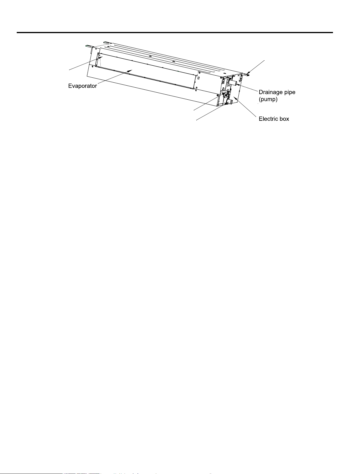
Parts and Functions
Supply air
Liquid and vapor ports
Drainage pipe (gravity)
Hanging bracket
1
Page 4
Safety
• This manual should be saved and stored close to this air conditioning equipment.
• There are two types if indications. Both are related to safety and should be strictly followed. "
issues that pose a risk of major injury or death. "
injury.
• After installation and start-up commissioning, please give the manual to the user. The manual should be kept in safe
place and close to the unit.
Caution" highlights issues that pose a risk of equipment or bodily
Warning" highlights
WARNING
• Installation and maintenance should be performed by an authorized agency. The wrong operation of this air condition
equipment may cause water damage, electric shock or re.
• Please install the unit on the top of a solid foundation or structure which is strong enough to support the unit.
• The installation of this condition equipment should follow local building codes.
• Use the right cable size, secure the terminal rmly, organize the cables well and make sure no tension is added on
cables. Cable insulation should not be damaged. Improper wire installation may lead to re.
• This unit is only compatible with R-410A refrigerant. If any other gas enters the system, it may lead to abnormal high
pressure which may cause damage or injury.
• Only use branches supplied by Haier. Use of any other branches will void warranty.
• Keep the condensate drain pipe away from toxic gas vents to prevent possible pollution of indoor environment.
• Care should be taken to ensure that there are no refrigerant leaks. R-410A is a heavy gas and will displace oxygen.
Ventilate the area if a leak if found.
• The unit is not explosion-proof. Please keep it away from ammable gases.
• The drain pipe should be installed per this manual to ensure proper drainage. The pipe should be well insulated to avoid
condensation. Wrong installation may lead to water damage.
• Both liquid pipe and the vapor pipe should be also well insulated. Not enough insulation may lead to system
performance deterioration or condensate formation.
• This equipment should not be used or serviced by personnel who have not been properly trained in its operation and
maintenance.
• Children should be supervised to ensure that they do not play on or near the equipment.
• Keep the appliance and its cord out of reach of children.
• The appliances are not intended to be operated by means of an external timer or separate remote-control system.
CAUTION
• Grounding wire should be connected to the grounding bar. The grounding wire cannot be connected to the gas pipe,
water pipe, lightening rod or the telephone grounding wire. Improper grounding may cause electric shock.
• A circuit breaker should be installed. If not, it may cause electric shocks or accidents.
• After installation, the air condition equipment should be powered on and passed the electric leakage current lest.
• If the ambient humidity is more than 80%, if the water discharge hole is blocked or the lter becomes dirty or the airow
speed changes, this may lead to condensate water leaks. There may also be some drops of water spraying out.
2
Page 5
Safety
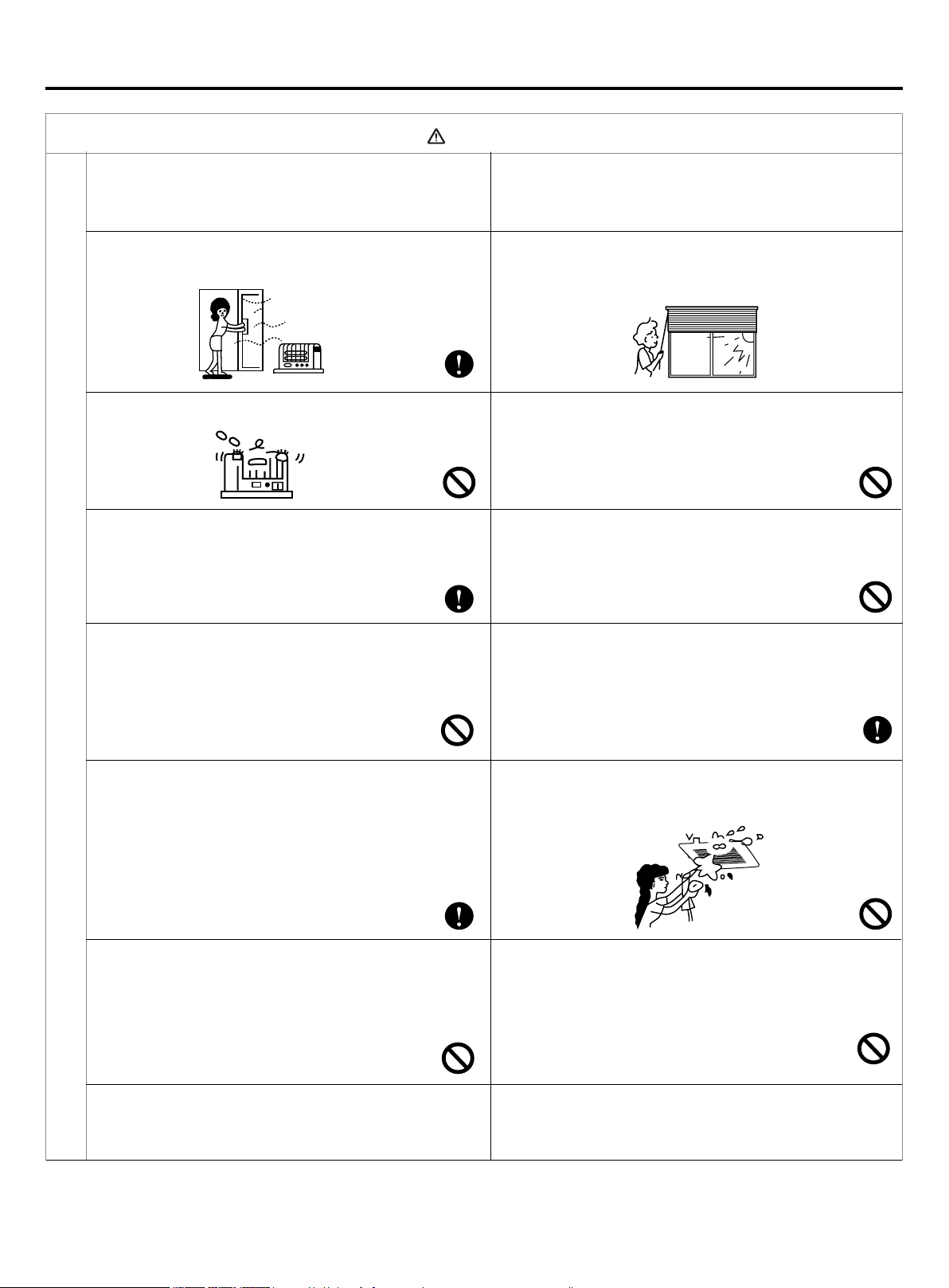
Attention
• Do not put any heating apparatus under the
indoor units. The heat may cause distortion of the
units.
• Pay attention to the ventilation to avoid anoxic injury.
• Do not place an open ame in the path of blowing air.
• Do not install in a corrosive environment. If the base
collapses, the unit may fall and cause damage,
product failure, personal injury or death.
• 3-minutes protection
To protect the unit, there is a 3-minute time-out after
the unit stops or after power is applied.
• Close the window to avoid outdoor air getting in.
Curtains or window shutters can be put down to avoid
the sunshine.
• Do not touch the power switch with the wet hand to
avoid power shock.
• Turn off the system and remove power when servicing
the unit.
• Do not use the unit for special purposes such
as preserving foods, works of art etc. It is an air
conditioner for comfort cooling / heating, not a
precision refrigeration system.
Notices during Operation
• Use the correctly rated breaker or fuse. Improper
breaker or fuse may lead to re, electric shock,
explosion, personal injury or death.
• Do not permit water or steam to enter the unit and
the wired controller. There is risk of unit failure, re,
electric shock, personal injury or death.
• Turn off the power to save energy if the unit will
be not used for a long period. If the unit is not
powered off, it will consume power.
• Don't remove power while system is running.
• Do not clean the unit with water spray. There is risk
of unit failure, re, electric shock, personal injury or
death.
• Keep ammable gas or combustibles away from the
unit. There is risk of product failure, re, personal
injury or death.
• Please keep children away from this air condition
equipment.
3
Page 6
Maintenance
Cleaning the air lter & air inlet grid.
• Don't remove the air lter except for cleaning, or faults may occur.
• When the air conditioner operates in the environment with too much dust, clean the air lter on a more regular basis
(generally once every two weeks).
Cleaning the Air Inlet/Outlet Grilles:
Attention
• Do not use gasoline, benzene, diluents, polishing powder or liquid insecticide to clean them.
• Do not clean them with hot water of over 122°F(50°C) to avoid fading or distorting.
• Wipe them with a soft dry cloth.
• Water or neutral dry cleaner is recommended if the dust cannot be removed.
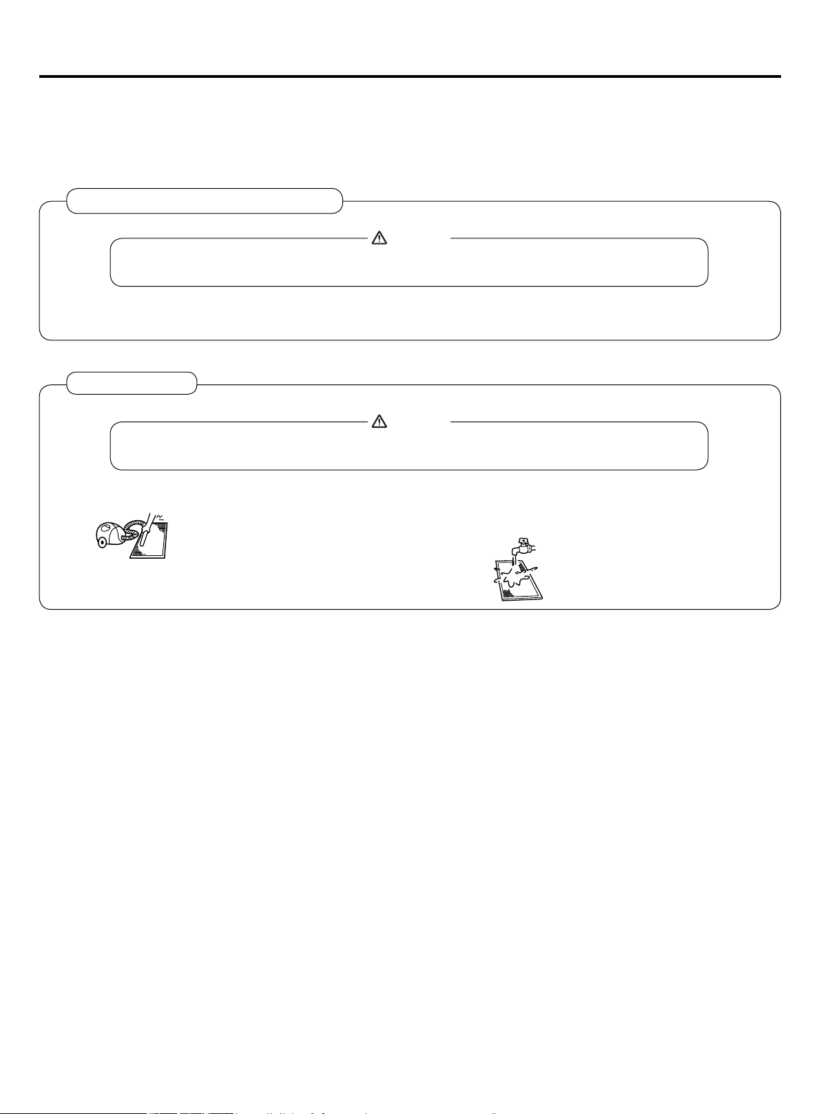
Cleaning Air Filter:
Attention
• Don't rinse the air lter with hot water of above 122
• Don't put the air cleaner near re to dry to avoid catching re.
ºF(
50°C) to avoid fading and distorting.
(A) Brush off dirt and vacuum.
(B) Wash with soft cloth and mild detergent.
(C) Shake water off and allow the lter to fully air dry before reinstalling.
4
Page 7

Fault Checkup
Please check the following when consigning repair service:
Symptoms Reasons
Water ow sound can be heard during starting operation, during operation
Water ow sound
or immediately after stopping operation. When it starts for 2-3 minutes, the
sound may become louder, which is the owing sound of refrigerant or the
draining sound of condensate water.
Cracking sound
Bad smell in outlet air
Flashing operating indicator
Awaiting indication
All these are not problems
Idle indoor unit still has sound of
refrigerant owing and radiating
temperatures.
Clicking sound when unit comes on.
Start or stop working automatically Check if it is set to Timer-ON and Timer-OFF.
Failure to work
During operation, the air conditioner may make a crackling sound, which
is caused from the temperature changes of the heat exchanger.
Clean lters and conrm the condensate drain pan and line
are clean and clear.
When switching it on again after power failure, turning on the manual
power switch will show the operating indicator ashes.
It displays the waiting indication as it fails to perform refrigerating operation
while other indoor units are in heating operation. When the operator set it to
the cooing or heating mode and the operation is opposite to the setting, it
displays the waiting indication.
To prevent oil and refrigerant from blocking the valve of idle units (off or
satised) while other indoor units are operating, some refrigerant ow is
allowed to pass through. This may result in some radiating temperature and
ow noise.
When the conditioner is powered on, the sound is made due to the
expansion valve resetting.
Check if there is a power failure.
Check if the supply fuse and breaker are disconnected.
Check if the unit is displaying any faults.
Check if wait symbol is displayed. This is due to other indoor units
connected to the same outdoor unit are running in the opposite mode.
System cannot heat and cool simultaneously.
Check if air intake port and air outlet port of outdoor units are blocked.
Check if the door and windows are open.
• Poor cooling &heating effects
Please make another check.
Under the following circumstances, immediately stop the operation, disconnect the manual supply switch and contact the
after-service personnel.
• When buttons are not exible and actuated;
• When there are foreign objects or ice in the unit;
• When it cannot be operated after exiting the protection mode;
• When other abnormal conditions occur.
Check if the ltering screen of the air cleaner is blocked with debris or dust.
Check if the fan setting is too low.
Check if the mode set to Fan mode.
Check if the temperature is set correctly.
5
Page 8

Installation Procedures
This manual cannot completely illustrate all the properties of the products you bought. Please contact the local Haier
distribution center if you have any question or request.
Caution: Choose a suitable installation location.
Avoid places with high salinity (salt water) and high sulfur gas. Unit will corrode and damage will not be covered by
warranty.
Avoid excess oil (including mechanical oil) and steam. This can reduce efciencies and product performance.
Avoid areas where machines generate high frequency electromagnetic waves. They can cause control issues.
Warning:
protect the machine from winds or earthquake, install according to regulations. Improper installation will cause accidents
due to unit coming loose and falling.
Indoor Units
1. The distance between air outlet and the ground should not
be more than 8.8ft (2.7m).
2. Select appropriate places for installation where the airow
can be spread evenly throughout the house. Arrange
proper locations for connecting pipes and lines as well as
the drainpipe to the outdoor.
3. Ceiling construction must be sturdy enough to hold the
weight of the unit.
4. Make sure that the connecting pipe, the drainpipe and
connecting guide line can be put into walls to connect the
outdoor units.
5. It is recommended to make the connecting pipe between
the outdoor and indoor units and the drainpipe as short as
possible.
6. Please read the attached installation instruction of the
outdoor unit for refrigerant charging if necessary.
7. The connecting ange should be checked by users.
8. Electrical appliances such as television, instruments,
devices, artwork, piano, wireless equipment and other
valuables should not be placed under the indoor unit as to
prevent condensate from dropping onto them and causing
damage.
Required Tools for Installation
• Brazing torch
• 15% silver phosphorous copper brazing alloy
• Wire stripper
• Soap-and-water solution or gas leakage
detector
• Torque wrench
• 17mm, 22mm, 26mm
• Tubing cutter
• Reaming tool
• Flaring tool
• Razor knife
• Measuring tape
• Level
• Vacuum pump
• Micron gauge
• Nitrogen
• Mini-Split AD-87 Adapter (1/4” to 5/16”)
• Non-adhesive Tape
• Adhesive Tape
• Electrical wiring
The following steps can be taken after selecting the installation place:
1. Cut a hole in the wall and insert connection pipe and connecting wires through a eld supplied PVC pipe. The hole
should be inclined slightly downward with an inclination of at least 1/100 (see Figure 1).
Figure 1
2. Before cutting the hole, ensure no pipe or rebar is placed behind the cutting position. Avoid cutting a hole near wires or
connection pipes.
3. Hang the unit on a horizontal and rm roof. If the unit base is not stable, it may cause noise, vibration or leakage.
4. Support the unit rmly and shape the connection pipe, connecting wires and drain pipe to allow them to easily get
through the hole.
6
Page 9

Installation Procedures
Dimension (unit: in.).
Model a b c d e f g h i
MVAD007~12MV2AA 16.5 35.1 14.6 33.5 7.3 25.2 3.6 29.9 6.0
MVAD018~24MV2AA 16.5 47.7 14.6 46.1 7.3 37.8 3.6 42.5 6.0
b
a
Hanger dimensions
h
c
Dimensions of air outlet
d
g
f
Dimensions of pump drainage
hole, OD Ø1"
e
Air in
Dimensions of natural
Dimensions of return air inlet
Dimensions of drain hose
drainage hole, OD Ø1"
Installation modes of Indoor unit
This series of air conditioners can be arranged in two air return modes: 1. Air return from the back (Factory default); 2. Air
return from the bottom (can be adjusted on site. See the following gures.)
Air return from the bottom 1Air return from the back Air return from the bottom 2
Note:
The downward air return mode will increase noise 3-5dB(A). It is recommended to install the air conditioner in downward
return air mode 2 if enough space is available.
Installation space and method
Body installation
1.Use 3/8" (M10) lifting bolts.
2.Ceiling removal: For different building structures, please consult with building personnel about actual conditions.
a. Ceiling reinforcement: Ensure the ceiling is horizontal and will not shake. The ceiling base frame must be reinforced.
b. Cut off and remove the ceiling base frame.
c. Reinforce the faces left when the ceiling is removed and further reinforce the base frame that fix both ends of the
ceiling.
d. After the unit installation is complete, it is time to install pipes and wires. Before installation, choose a suitable
installation position and determine the outgoing direction of pipes. Especially in case that a ceiling exists, please pull
refrigerant tubing, drain hose, indoor and outdoor connecting wires, control wires to their connection positions prior to
hanging the machine.
7
Page 10

Installation Procedures
Installation space Installation mode
Electric control
˃40in
˃4in(100mm)
Reserve 24in×24in
(600mm×600mm) access hole
enclosure
(1000mm)
˃24in
(600mm)
Level the unit within 0.2in(5mm).
If end A is to drain water, ensure end B is slightly higher than the end A
to facilitate drainage.
Otherwise, ensure end A is slightly higher than end B.
4-Ø3/8"(M10)hanging bolt
8-Ø3/8"(M10) nut
8-Ø3/8"(Ø10) Washer
Installation of air-inlet grille
The angle of air-inlet grille should be parallel with that of air inlet direction, otherwise it will cause more noise. Example
shown to the right.
Correct Wrong
Air inAir in
Duct Installation of Indoor Units:
1.Installation of the duct work:
With a square supply duct, the bore shouldn't be less than the sizes of air outlet duct.
2.Installation of the air return duct: Connect one side of the air return duct to the air return of the indoor units with rivets,
with the other side connected to air return shutter, as shown in Fig. 1.
3.Insulating Supply Ducts: Supply and return air ducts should be insulated.
Air return shutter
Air return pipe
Indoor unit
Revit
Fig.1
Connection of oil return pipe
Selection of fan outlet
This machine uses a DC motor. Multiple ESP adjustments are available. The factory default is standard ESP. The ESP &
Silent mode can be set according to the static pressure and the noise requirement. Setting ranges are as follows:
Model Ultra-Silent Silent Standard ESP default High ESP Super High ESP
Grade 1 2 3 4 5
Operation:
YR-E17 wired controller: With the display on, press Fan + Set keys for 5s to enter static pressure set mode. The static
pressure icon will ash and current static pressure will display. Press ▼▲ key to change static pressure grade, then press
the Set key to conrm.
Note:
This series are low ESP duct, all the sets above must be handled by a wired controller.
8
Page 11

Installation Procedures
Installation of drain hose
Connection of indoor drain hose
1. Please use the accessory drain hose to connect indoor unit's water outlet and PVC pipe. Use snap rings to tighten
them as shown in the following gure:
2. Please use rigid PVC adhesive for connection of other pipes and ensure there is no leakage.
3. Drain hose must be wrapped with insulation sleeve and tightened with a strap to prevent air leakage from producing
condensate.
4. To prevent water owing back into air conditioner when the unit stops running, drain hose should decline to the
drainage side with an inclination of above 1/100. Drain hose expansion or water accumulation should be prevented, or
else it will cause abnormal noise.
5. When connecting the drain hose, do not pull on it to avoid the pipe connections from getting loose or disconnected.
Drain hose should not be pulled out laterally for more than 8in(200mm) and should be supported every 31-39in(0.8-
1.0m) to avoid bending.
6. The end of drain hose should be more than 2in(50mm) away from the ground or the bottom of drainage tank. It should
not be put in water. To directly drain condensate into drainage ditch, the drain hose must be U-shaped to avoid smell
from entering through the hose into room.
Set a supporting point at every 31-39in(0.8-1.0m)
8in(200mm)
2-4in(50-100mm)
8in(200mm)
27.5in(700mm)
Drainage test
Before the test, ensure the drain hose is clear and all connections are
tightly sealed.
Then perform the drainage test as follows:
1. Add about 0.132gal (500ml) of water into the water pan through
water injection hole.
2. Switch on the power and operate the unit in cooling mode. Check
that the water outlet drains water normally and that there are no
leakages at the connections. After the drainage test is complete,
replace the water injection hole plug. For the position of water
injection hole, see the gure on the right:
8in(200mm)
27.5in(700mm)
24in
(600mm)
2-4in(50-100mm)
9
Page 12

Installation Procedures
Pipe Length & Height Difference
Please refer to the attached manual of outdoor units.
Model MVAD007~018MV2AA MVAD024MV2AA
Tubing Size
in(mm)
Tubing Material Seamless copper pipe rated for R410A refrigerant
Tubing Materials & Specications
Special tools for R410A should be used for cutting and enlarging pipes.
Refrigerant Recharge Amount
Add the refrigerant according to the installation instruction of outdoor unit. The addition of R410A refrigerant must be
performed with a digital scale to ensure the proper charge. Compressor failure can be caused by over or under charging
the system.
Connecting Procedures of Refrigerant Tubing
Connect all the refrigerant tubes via are connections.
• Dual wrenches must be used in the connection of indoor unit tubing.
• For tightening torque refer to the right table.
Gas pipe Ø1/2"(Ø12.7) Ø5/8"(Ø15.88)
Liquid pipe Ø1/4"(Ø6.35) Ø3/8"(Ø9.52)
Outer Diameter of Tubing
in(mm)
wrench
Cutting and Enlarging
• Cut the tube to the needed length.
• Ream the cut to remove shoulder. Do this with the tube facing down to help llings fall out.
• Add supplied are nut to tube.
• Use 45° are tool to create are.
Ø1/4"(Ø6.35) 104.4(11.8) 13 (18)
Ø3/8"(Ø9.52) 216.8(24.5) 30 (40)
Ø1/2"(Ø12.7) 443.7(49.0) 43 (59)
Mounting Torque
lb-in(N-m)
Flare Torque Spec
ft-lb (N-m)
Wire Connections
1. Connecting using circular crimp terminals:
The method of using circular terminal is shown in the gure. Take off the screw, connect it to the
terminal after placing it through the ring at the end of the lead and tighten it down.
2. Connecting using straight terminals:
The method of using straight terminals is shown as follows: loosen the screw before putting the wire into the terminal
block, tighten the screw and conrm it has been tightened by pulling the line gently.
3. Clamp the wires:
Secure the wires with clips which should press on the insulation of the wires.
terminal tier
Connecting
circular
terminals:
correct
pressing
pressing clip
wrong
pressing
10
Page 13

Electrical Wiring
WARNING
• Follow local codes when selecting wire gauge and connecting to house power.
• Use the cable strain relief clips and locking conduit clamps to prevent wires from being pulled off terminal posts.
• Unit must be properly grounded. Do not use water or gas piping, phone ground or lightning rod.
Attention
• Only copper wire can be used. A properly sized breaker should be provided, or electric shock may occur.
• Unit requires 220VAC - 2 voltage wires and a ground. No neutral.
• All indoor units should be wired to the same breaker to prevent some of the units from being powered off while others
are energized.
• Controller wiring and refrigerant tubing can be arranged and ran together.
• Disconnect power from both outdoor and indoor units prior to servicing any component in the system.
Supply Wiring Drawing
outdoor
L1(L) L2(N)
power source: 208/230V~, 60Hz
Indoor 1
L1(L) L2(N)
power source: 208/230V~, 60Hz
• Indoor units and outdoor units should be connected to separate power breakers.
• Indoor units must share one single electrical breaker. Circuit breaker specications should be calculated. It is
recommended to have both indoor & outdoor units connected to GFCI and surge devices.
Indoor 2 Indoor 9
L1(L) L2(N)
......
L1(L) L2(N)
11
Page 14

Electrical Wiring
Signal Wiring Drawing
Outdoor
P Q A B C
Communication wire between indoor & outdoor
without polarity
Indoor 1
(950 CASSETTE)
Indoor 2
P QA B C P Q A B C P Q A B C
Indoor 4
Indoor 5
P Q A B C P Q A B C P Q A B C
A B C A B C
Wired controller
Indoor 7
Indoor 8
Control wire for wired controller with polarity
Indoor 3
Indoor 6
Wired controller
Indoor 9
A B C
A B C
Wired controller
Wired controller
P Q A B C P Q A B C P Q A B C
A B CA B C
Wired controller
Wired controller
A B CA B C
Wired controller Wired controller
Outdoor units are of parallel connection via three lines with polarity. The main unit, central control and all indoor units
are of parallel connection via two lines without polarity.
There are three ways of connecting the line control and indoor units:
A. One wired control to control multiple units, i.e. 2-9 indoor units, as shown in the above gure, (1-3 indoor units). The
indoor unit 3 is the wire controlled main unit and others are the wired controlled sub units. The remote control and the
main unit (directly connected to the indoor unit of wired control) are connected via three wires with polarity. Other
indoor units and the main unit are connected via three lines with polarity. SW01 on the main unit of wired control is set
to 0 while SW01 on other sub units of wired control are set to 1, 2 and so on in turn. (Please refer to the code setting A
at page 14)
B. One wired control controls one indoor unit, as shown in the above gure (indoor unit 4-8). The indoor units and the
wired control are connected via three lines with polarity.
C. Two wired controls control one indoor unit, as shown in the gure (indoor unit 9). Either of the wired controls can be
set to be the master wired control while the other is set to be the auxiliary wired control. The master wired control and
indoor units, and the master and auxiliary line controls are connected via three lines with polarity.
Note: For DC motor/low ESP duct type, the PCB comes with the terminal blocks. Please be sure to pay attention to do
the wiring according to the labels. The power lines and signal lines go through the metal wire hole separately with the
protective sleeve of the connecting line.
12
Page 15

Electrical Wiring
Wire gauge size and breaker size for total indoor amp draw. Current NEC guidelines and local codes will trump this chart.
Items
Total
Current of
Indoor Units(A)
<7 14(2.5) 65.6(20) 10 10 A,30 mA,0.1S or below
≥7 and <11 12(4) 65.6(20) 15 15 A,30 mA,0.1S or below
≥11and <16 10(6) 82(25) 20 20 A,30 mA,0.1S or below
≥16 and <22 8(8) 98.4(30) 30 30 A,30 mA,0.1S or below
≥22 and <27 6(10) 131(40) 30 30 A,30 mA,0.1S or below
• The electrical power line and signal lines must be tightened.
• Every indoor unit must have a ground connection.
• The power wire should be size up if it exceeds the permissible length.
• Shielding of the wire of all the indoor and outdoor units should be connected together and grounded at one point.
• Signal lines should not exceed 3280ft(1000m).
Wired Controller ABC Chart
Length of Controller Wire ft (m) Wiring Dimensions AWG (mm2)
Cross
Section
AWG
2
)
(mm
Length
in.(m)
Rated
Current of
Overow
Breaker(A)
Rated current of residual
Circuit Breaker(A)
Ground Fault Interrupter(mA)
Response time(S)
Cross Sectional
Area of Signal Line
16 AWG (1.25mm
2
)
<328(100) 22(0.3) x 3 core shielding line
≥328(100) and <656(200) 20(0.5) x 3 core shielding line
≥656(200)and <984(300) 18(0.75) x 3 core shielding line
≥984(300) and <1312(400) 16(1.25) x 3 core shielding line
≥1312(400) and <1968(600) 14(2) x 3 core shielding line
• The shielding lay of the controller wire must be grounded at one end.
• The total length of the controller wire shall not be more than 1968ft(600m).
13
Page 16

Electrical Wiring
Dipswitch Setting
• The dip switch is set to the "On" position if “1” is indicated in the table. The dip switch is set to the "Off" position if "0" is
indicated in the table.
• Dip switches set in the factory to on are marked with red.
Denition principles of code switches:
(A) Denition of SW01:
SW01_1-4 is used to set indoor address when grouping multiple indoor units connected to single wired controller YRE16B or YR-E17.
SW01_5-8 set capacity of the indoor unit (factory set). Must only set when replacing board.
[1] [2] [3] [4] Address of wire controlled indoor unit (group address)
0 0 0 0 0# (wire controlled master unit) (default)
SW01_1
SW01_2
SW01_3
SW01_4
SW01_5
SW01_6
SW01_7
SW01_8
Address of wire
controlled indoor unit
(group address)
Capability of indoor
unit
0 0 0 1 1# (wire controlled slave unit)
0 0 1 1 2# (wire controlled slave unit)
0 0 1 1 3# (wire controlled slave unit)
… … … … ……
1 1 1 1 15# (wire controlled slave unit)
[5] [6] [7] [8] Capability of indoor unit
0 0 0 0 5000BTU(0.6HP)
0 0 0 1 7000BTU(0.8HP)
0 0 1 0 9000BTU(1.0HP)
0 0 1 1 11000BTU(1.2HP)
0 1 0 0 12000BTU(1.5HP)
0 1 0 1 15000BTU(1.7HP)
0 1 1 0 18000BTU(2.0HP)
0 1 1 1 22000BTU(2.5HP)
1 0 0 0 27000BTU(3.0HP)
1 0 0 1 28000BTU(3.2HP)
1 0 1 0 36000BTU(4.0HP)
1 0 1 1 45000BTU(5.0HP)
1 1 0 0 54000BTU(6.0HP)
1 1 0 1 72000BTU(8.0HP)
1 1 1 0 90000BTU(10.0HP)
1 1 1 1 135000BTU(15.0HP)
Note : A wired controller can connected to at most sixteen ultrathin air-duct indoor units.
14
Page 17

Electrical Wiring
(B) Denition and description of SW03
SW03_1-8 is used to set indoor unit address on system. Set address only if using central controller YCZ-A004. Leave
default if no central controller is used.
SW03_1
SW03_2
~
SW03_8
Note:
• Set the address by code when connecting the centralized controller, gateway or control system.
• Address of centralized controller = communication address + 0 or +64.
SW03_ 2=OFF, address of centralized controller = communication address + 0 = communication address
SW03_ 2=ON, address of centralized controller = communication address + 64 (applies when centralized controller is
used and there are more than 64 indoor units)
Address setting
mode
Code-set indoor
unit address
and centralized
controller address
0 Automatic address setting or wired controller address setting (default)
1 Code-set address
2 3 4 5 6 7 8 Address of indoor unit
0 0 0 0 0 0 0 0# (Default) 0# (Default)
0 0 0 0 0 0 1 1# 1#
0 0 0 0 0 1 0 2# 2#
… … … … … … … … …
0 1 1 1 1 1 1 63# 63#
1 0 0 0 0 0 0 0# 64#
1 0 0 0 0 0 1 1# 65#
1 0 0 0 0 1 0 2# 66#
… … … … … … … … …
1 1 1 1 1 1 1 63# 127#
Address of centralized
controller
15
Page 18

Electrical Wiring
Dip Switch Setting of YR-E17 Wired Controller
Function switches
DIP switch On/Off station Function Default setting
Sw1
Sw2
Sw3
Sw4
Sw5
Sw6
Sw7
Sw8
On Slave wired controller
Off Master wired controller
On Ambient temp. display on
Off Ambient temp. display off
On Collect ambient temp. from PCB of indoor
Off Collect ambient Temp. from wired controller
On Non-volatile memory invalid
Off Non-volatile memory valid
On Old protocol
Off Self adaption
On reserved
Off reserved
On Model with Up/Down and Left/Right swing
Off Model with Up/Down swing
On Fresh Air unit
Off General unit
Off
Off
Off
Off
Off
Off
Off
Off
For other wired remote controller settings, please refer to controller manual.
The difference between master and slave wired controller
Comparison item Master wired controller Slave wired controller
1.ON/OFF, Mode, Fan speed, Temp, Setting, Swing, Energy saving, Clock
Function All function
function, Mode Setting, Screen Saving and Child lock are available.
2.Cancel the lter cleaning icon.
3.Look up the detailed parameter and malfunction code.
16
Page 19

Test Run & Failure Code
Before Test Run
• Connect it to the power supply of the outdoor units to energize the heating belt of the compressor. To protect the
compressor at startup, power it on 12 hours prior to the operation.
Check if the connections of the drainpipe and wire connection lines are correct.
The drainpipe shall be placed at the lower part while the connection line placed at the upper part. Insulating measures
should be taken such as winding the drainpipe especially on the indoor units with insulating materials.
The drain pipe should be installed as a slope to avoid protruding from the upper part and concaving at the lower part.
Checkup of Installation
Check if the mains voltage is matching
Check for any leaks at the piping joints
Check if the connection of the main power for the indoor & outdoor units are correct
Check if the serial numbers of the terminals are matched properly
Check if the installation place meets the requirement
Check if there is too much noise
Check if the connecting line is fastened
Check if the refrigerant and condensation lines are insulated
Check if the water is drained to the outside
Check if the indoor units are positioned
Test Run
Ask the installation technician to perform a test run. Compare the testing procedures according to the manual and check if
the temperature control works properly.
When the machine fails to start because of the room temperature, the following procedure can be used to force
compulsive running mode. The function is not available for the type with remote control.
• Set the YR-E17 wired controller to cooling/heating mode, press "ON/OFF" button for 10
seconds to enter into the compulsive cooling/heating mode. Press "ON/OFF" button again to
quit the compulsive running and stop the operation of the system.
Fault Remedies
When any fault appears, refer to “Inquiry of fault records of indoor units" at the previous page, consult the fault code of line
control or the number of LED ashes on the control panel of the indoor units/health lamp of receiving window of remote
control. Refer to the below table lookup fault descriptions.
Indoor Unit Faults
Failure code at
wired controller
01 1
02 2
03 3
04 4
05 5
06 6
07 7
08 8
09 9
12 12
14 14
18 18
20 20 Corresponding faults of outdoor units
PCB LED5(Indoor Units)/ Receiver
Timer Lamp (Remote Controller)
Fault Descriptions
Fault of indoor unit ambient temp. sensor TA
Fault of indoor unit pipe temp. sensor TC1
Fault of indoor unit pipe temp. sensor TC2
Fault of indoor unit dual heat source temp. sensor
Fault of indoor unit EEPROM
Fault of communication between indoor & outdoor units
Fault of communication between indoor unit and wired control
Fault of indoor unit oat switch
Fault of duplicate indoor unit address
Fault of indoor unit 50Hz Zero-crossing
Fault of indoor unit DC motor
BS valve box or 4WV switch failure
17
Page 20

Qingdao Haier Air Conditioner Electric Co.,Ltd.
Haier Industrial Park,Qianwangang Road,Eco-Tech Development Zone,Qingdao 266555,
Shandong,P.R.C.
 Loading...