

Page 1
SERVICE MANUAL
LED TV
Model No.
MSD6586
LE49K6500U
Chassis
WARNING
This service information is designed for experienced repair technicians only and is not designed for use by the general public.
It does not contain warnings or cautions to advise non technical individuals of potential dangers in attempting to service a product.
Products powered by electricity should be serviced or repaired only by experienced professional technicians. Any attempt to
service or repair the product or products dealt with in this service information by anyone else could result in serious injury or death.
Page 2

Service Manual
Model No.:
Chapter 1: General Information
1-1. Table of Contents
1. General Information...........................................................................
1-1. Table of Contents
1-2. General Guidelines
1-3. Important Notice
1-4. How to Read this Service Manual
6SHFL¿FDWLRQV....................................................................................
3. Location of Controls and Components...........................................
3-1. Board Location
3-2. Main Board & AV Board
3-3. Power board
3-4. LCD Panel 13
4. Disassemble and Assemble..........................................................
4-1 Remove the Pedestal
4-2 Remove the Back Cover 14
4-3 Remove the Adhesive
4-4 Remove the Main Board 15
Tape 14
1
1
3
3
6
6
88
8
8
11
14
14
4-5 Remove the Speaker 15
4-6 Remove the Remote Control Board 16
4-6 Remove the Power board 16
5. Installation Instructions..…....………………...........………….........
5-1 External Equipment Connections
5-2 HDMI Connections 21
6. Operation Instructions....…....………………...........………….........
6-1 Front Panel Controls
6-2 Back Panel Controls
6-3 Universal Remote Control
7. Electrical Parts…....………………...........………….........................
7-1. Block Diagram
7-2. Circuit Diagram
7-3. Wiring Connection Diagram
17
17
24
24
24
25
26
26
27
36
- 01 -
Page 3

Service Manual
Model No.:
8. Measurements and Adjustments
8-1. How to enter into the factory model
8-2. How to update software
8-3. How to enter into the Hotel Model
........…………............................
9. Trouble-shooting…………..............................................................
9-1. Simple Check 51
9-2. Main Board Failure Check
9-3. Panel Failure
37
48
49
50
51
52
58
- 02 -
Page 4

Service Manual
Model No.:
1-2. General Guidelines
When servicing, observe the original lead dress. If a short circuit is found, replace all parts
which have been overheated or damaged by the short circuit.
After servicing, see to it that all the protective devices such as insulation barriers, insulation
papers shields are properly installed.
After servicing, make the following leakage current checks to prevent the customer from
being exposed to shock hazards.
1) Leakage Current Cold Check
2) Leakage Current Hot Check
3) Prevention of Electro Static Discharge (ESD) to Electrostatically Sensitive
1-3. Important Notice
1-3-1. Follow the regulations and warnings
Most important thing is to list up the potential hazard or risk for the service personnel to
open the units and disassemble the units. For example, we need to describe properly
how to avoid the possibility to get electrical shock from the live power supply or charged
electrical parts (even the power is off).
This symbol indicates that high voltage is present inside.It is dangerous to
make any king of contact with any inside part of this product.
This symbol indicates that there are important operating and maintenance
instructions in the literture accompanying the appliance.
1-3-2. Be careful to the electrical shock
7R SUHYHQW
to rain or excessive moisture. This TV must not be exposed to dripping or splashing water,
DQG REMHFWV ¿OOHG ZLWK OLTXLG VXFK DV YDVHV PXVW QRW EH SODFHG RQ WRS RI RU DERYH WKH 79
GDPDJH ZKLFK PLJKW UHVXOW LQ HOHFWULF VKRFN RU ¿UH GR QRW H[SRVH WKLV 79 VHW
1-3-3. Electro static discharge (ESD)
Some semiconductor (solid state) devices can be damaged easily by static electricity. Such
components commonly are called Electrostatically Sensitive (ES) Devices. The following
techniques should be used to help reduce the incidence of component damage caused by
electros static discharge (ESD).
1-3-4. About lead free solder (PbF)
This product is manufactured using lead-free solder as a part of a movement within the
consumer products industry at large to be environmentally responsible. Lead-free solder
must be used in the servicing and repairing of this product.
8VH WKH JHQHZLQJ SDUWV VSHFL¿HG SDUWV
Special parts which have purposes of fire retardant (resistors), high-quality sound
(capacitors), low noise (resistors), etc. are used.
When replacing any of components, be sure to use only manufacture's specified parts
shown in the parts list.
Safety Component
Ɣ &RPSRQHQWV LGHQWL¿HG E\ PDUN KDYH VSHFLDO FKDUDFWHULVWLFV LPSRUWDQW IRU VDIHW\
- 03 -
Page 5

1-3-6 Safety Check after Repairment
Service Manual
Model No.:
&RQ¿UP WKDW WKH
in the original positions, or whether there are the positions which are deteriorated around
the serviced places serviced or not. Check the insulation between the antenna terminal or
external metal and the AC cord plug blades. And be sure the safety of that.
VFUHZV SDUWV DQG ZLULQJ ZKLFK ZHUH UHPRYHG LQ RUGHU WR VHUYLFH DUH SXW
General Servicing Precautions
1.
Always unplug the receiver
a. Removing or reinstalling any component, circuit board module or any other receiver
assembly.
b. Disconnecting or reconnecting any receiver electrical plug or other electrical
connection.
c. Connecting a test substitute in parallel with an electrolytic capacitor in the receiver.
CAUTION: A wrong part substitution or incorrect polarity installation of electrolytic
capacitors may result in an explosion hazard.
2. Test high voltage only by measuring it with an appropriate high voltage meter or other
voltage measuring device (DVM, FETVOM, etc) equipped with a suitable high voltage
probe.
Do not test high voltage by "drawing an arc".
3. Do not spray chemicals on or near this receiver or any of its assemblies.
AC power cord from the
AC power source before;
4. Unless specified otherwise in this service manual, clean electrical contacts only by
applying the following mixture to the contacts with a pipe cleaner, cotton-tipped stick or
comparable non-abrasive applicator; 10% (by volume) Acetone and 90% (by volume)
isopropyl alcohol (90%-99% strength).
CAUTION: 7KLV LV D ÀDPPDEOH PL[WXUH
8QOHVV VSHFL¿HG RWKHUZLVH LQ WKLV VHUYLFH PDQXDO OXEULFDWLRQ RI FRQWDFWV LV QRW UHTXLUHG
Capacitors may result in an explosion hazard.
5. Do not defeat any plug/socket B+ voltage interlocks with which receivers covered by this
service manual might be equipped.
6. Do not apply AC power to this instrument and/or any of its electrical assemblies unless
all solid-state device heat sinks are correctly installed.
7. Always connect the test receiver ground lead to the receiver chassis ground before
connecting the test receiver positive lead.
Always remove the test receiver ground lead last. Capacitors may result in an explosion
hazard.
8VH ZLWK WKLV UHFHLYHU RQO\ WKH WHVW ¿[WXUHV VSHFL¿HG LQ WKLV VHUYLFH PDQXDO
CAUTION: 'R QRW FRQQHFW WKH WHVW ¿[WXUH JURXQG VWUDS WR DQ\ KHDW VLQN LQ WKLV UHFeiver.
9. Remove the antenna terminal on TV and turn on the TV.
10. Insulation resistance between the cord plug terminals and the eternal exposure metal
should be more than Mohm by using the 500V insulation resistance meter.
11. If the insulation resistance is less than M ohm, the inspection repair should be required.
If you have not the 500V insulation resistance meter, use a Tester. External exposure
metal: Antenna terminal Headphone jack
- 04 -
Page 6

Service Manual
Model No.:
Electrostatically Sensitive (ES) Devices
Some semiconductor (solid-state) devices can be damaged easily by static electricity.
Such components commonly are called Electrostatically Sensitive (ES) Devices.
Examples of typical ES devices are integrated circuits and some field-effect transistors
and semiconductor "chip" components. The following techniques should be used to help
reduce the ncidence of component damage caused by static by static electricity.
1. Immediately before handling any semiconductor component or semiconductorequipped assembly, drain off any electrostatic charge on your body by touching a known
earth ground.
strap device, which should be removed to prevent potential shock reasons prior to applying
power to the unit under test.
2. After removing an electrical assembly equipped with ES devices, place the assembly
on a conductive surface such as aluminum foil, to prevent electrostatic charge buildup or
exposure of the assembly.
Alternatively, obtain and wear a commercially available discharging wrist
3. Use only a grounded-tip soldering iron to solder or unsolder ES devices.
4. Use only an anti-static type solder removal device. Some solder removal devices not
FODVVL¿HG DV DQWLVWDWLF FDQ JHQHUDWH HOHFWULFDO FKDUJHV VXI¿FLHQW WR GDPDJH (6 GHYLFHV
'R QRW XVH IUHRQSURSHOOHG FKHPLFDOV 7KHVH FDQ JHQHUDWH HOHFWULFDO FKDUJHV VXI¿FLHQW
to damage ES devices.
6. Do not remove a replacement ES device from its protective package until immediately
before you are ready to install it.
(Most replacement ES devices are packaged with leads electrically shorted together by
conductive foam, aluminum foil or comparable conductive material).
7. Immediately before removing the protective material from the leads of a replacement
ES device, touch the protective material to the chassis or circuit assembly into which the
device will be installed.
CAUTION: Be sure no power is applied to the chassis or circuit, and observe all other
safety precautions.
8. Minimize bodily motions when handling unpackaged replacement ES devices.
(Otherwise harmless motion such as the brushing together of your clothes fabric or the
OLIWLQJ RI \RXU IRRW IURP D FDUSHWHG ÀRRU FDQ JHQHUDWH VWDWLF HOHFWULFLW\ VXI¿FLHQW WR GDPDJH
an ES device.)
1-3-7. Ordering Spare Parts
Please include the following informations when you order parts. (Particularly the Version
letter)
1. Model number, Serial number and Software Version
The model number and Serial number can be found on the back of each product and the
Software Version can be found at the Spare Parts List.
2. Spare Part No. and Description
<RX FDQ ¿QG WKHP LQ WKH 6SDUH 3DUWV /LVW
- 05 -
Page 7

1-3-8. Photo used in this manual
The illustration and photos used in this Manual may not base on the final design of
products, which may differ from your products in some way
1-4. How to Read this Service Manual
Using Icons:
,FRQV DUH XVHG
each icon is described in the table below:
Note:
A “note” provides information that is not indispensable, but may nevertheless be valuable
to the reader, such as tips and tricks.
WR DWWUDFW WKH DWWHQWLRQ RI WKH UHDGHU WR VSHFL¿F LQIRUPDWLRQ 7KH PHDQLQJ RI
Service Manual
Model No.:
.
Caution:
A “caution” is used when there is danger that the reader, through incorrect manipulation,
may damage equipment, loose data, get an unexpected result or has to restart(part of) a
procedure.
Warning:
A “warning” is used when there is danger of personal injury.
Reference:
A “reference” guides the reader to other places in this binder or in this manual, where he/
VKH ZLOO ¿QG DGGLWLRQDO LQIRUPDWLRQ RQ D VSHFL¿F WRSLF
- 06 -
Page 8
Service Manual
Model No.:
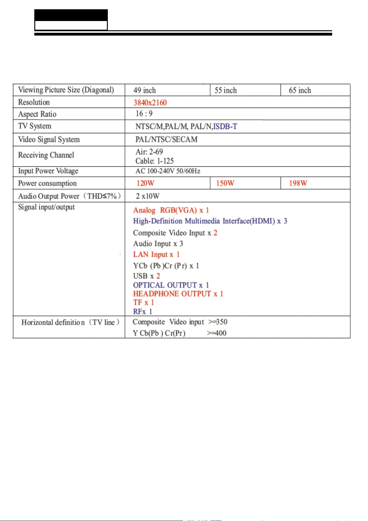
6SHFL¿FDWLRQV
- 07 -
Page 9
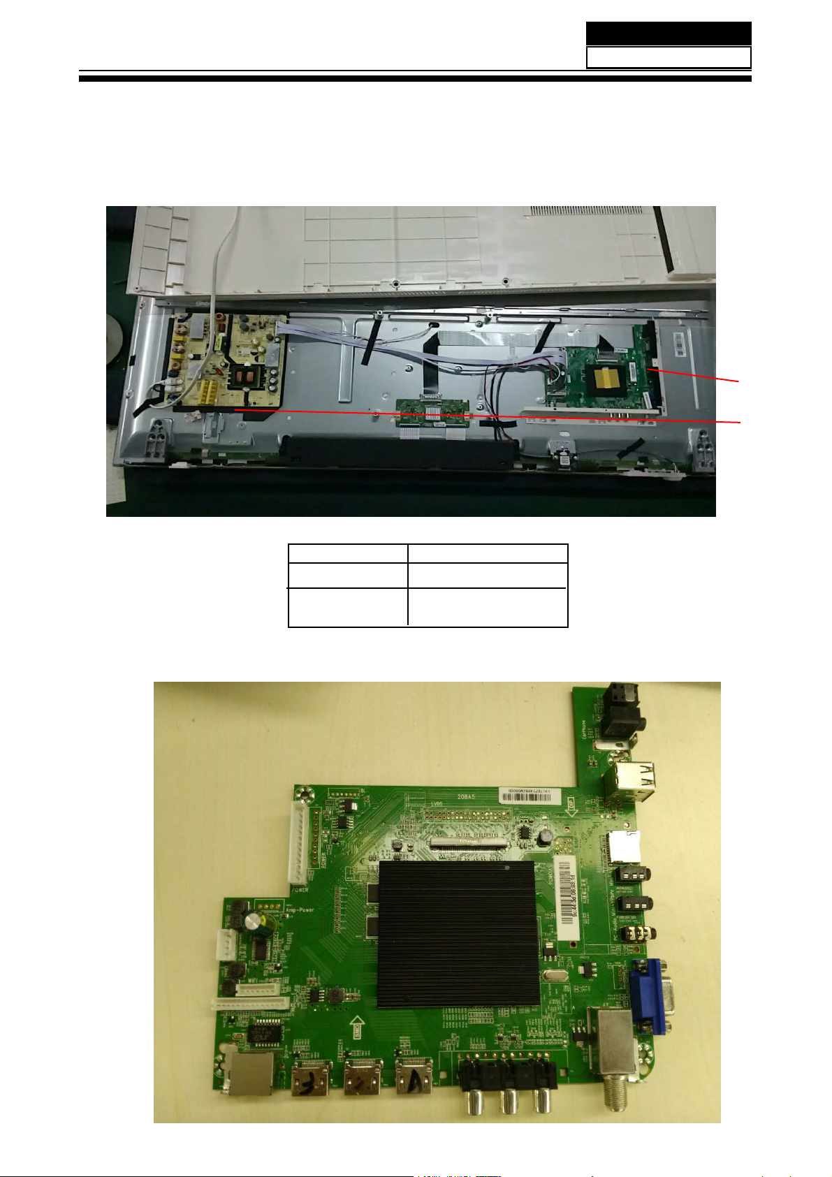
3. Location of Controls and Components
3-1 Board Location
Service Manual
Model No.:
A Board
B Board
3-2 Main Board
No. Description
A Board Mainboard
B
Board
Power Supply
- 08 -
Page 10
Service Manual
Model No.:
3-2-1 Function Description:
Main Board
Pr
ocess signal which incept from exterior equipment then translate into signal that panel
can display.
3-2-2 Connector denition
Main board connector
Power connectors ( J 20 )
Notes:
J 20-Pin 3: Backlight on/off:
he system can turn on or turn off the backlight of TFT LCD Panel through the power
T
supply unit path.
J 20-Pin 5: System power on / standby
System board will use this pin to control system power.
J 20-Pin 3: Control the luminance of backlight
The system can generate the PWN signal to control the strength of TFT LCD Panel’s
backlight through this connector
Speaker connector (CN604)
Pin number Signal name Description
1 RSPK+ RSPK+
2 RSPK- RSPK3 LSPK- LSPK4 LSPK+ LSPK+
- 09 -
Page 11
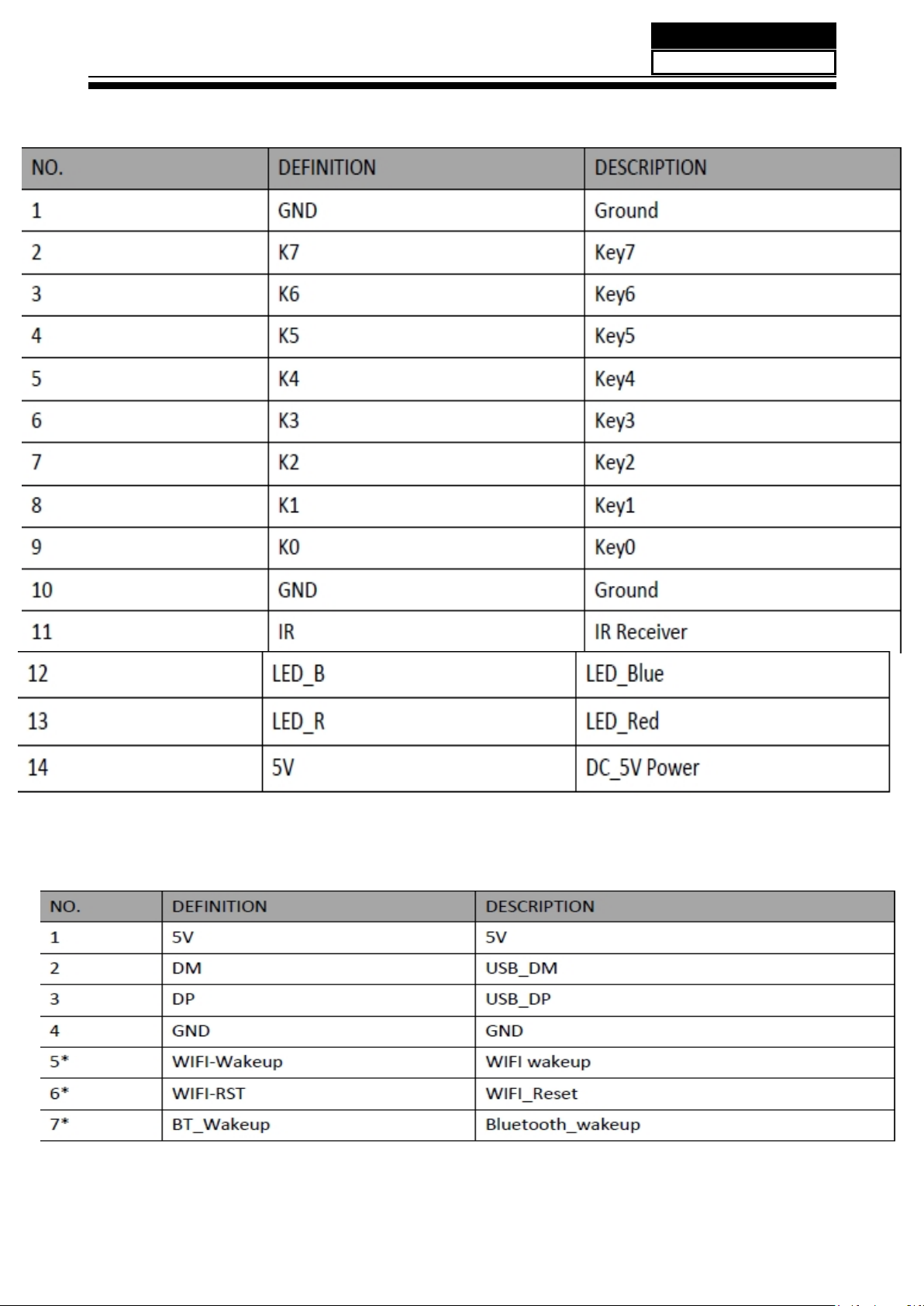
Keypad and remote connector ( 2)Keypad and remote connector ( 2)Keypad and remote connector (J 2)
Service Manual
Model No.:
WIFI J ACK J 25
- 10 -
Page 12
Service Manual
Model No.:
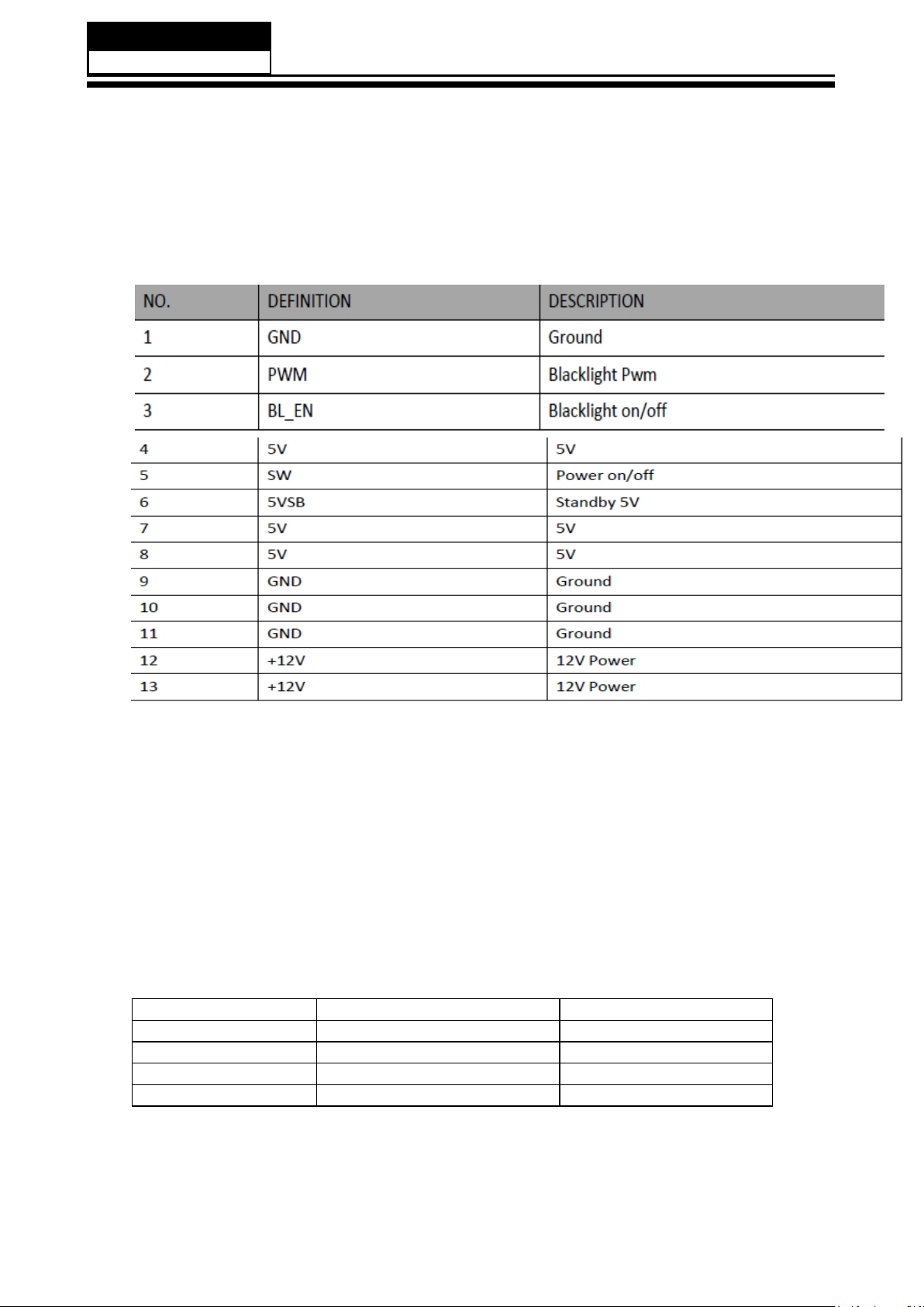
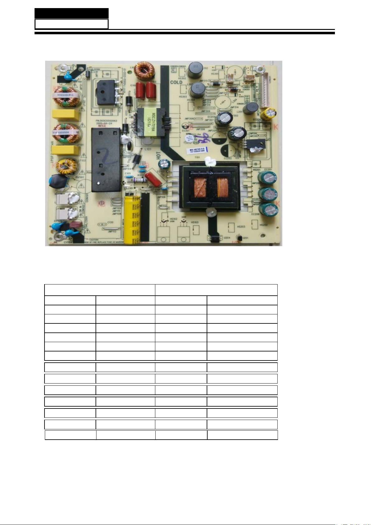
3-3. Power Board
3-3-1 Function Description:
Supply power for Main board, Panel.
3-3-2Connectordefinition
CON201
Pin number Signal name
1
2
3
4
5
6
7 +5V
8
9
10
11
12
13
SGND
AD
ON/BK
+5V
ON/OFF
+5VSTB
+5V
GND
GND
GND
+12V
+12V
- 11 -
Page 13
3-4. LED Panel
Service Manual
Model No.:
LSC490FN02-W/
- 12 -
Page 14
Service Manual
Model No.:
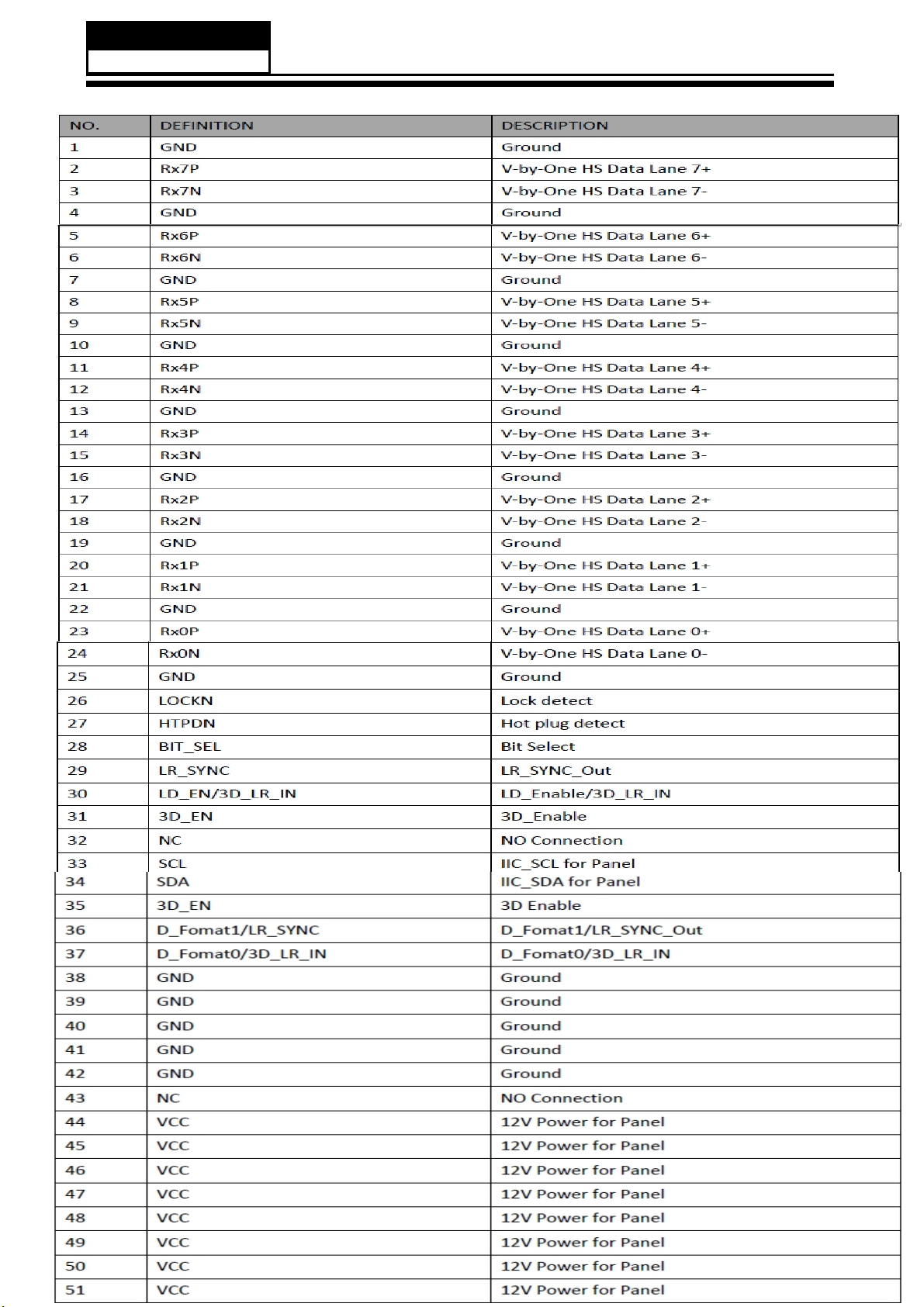
3-4-1.Connector de finition
Page 15
Service Manual
Model No.:
4. Disassemble and assemble
4-1 Remove the Pedestal
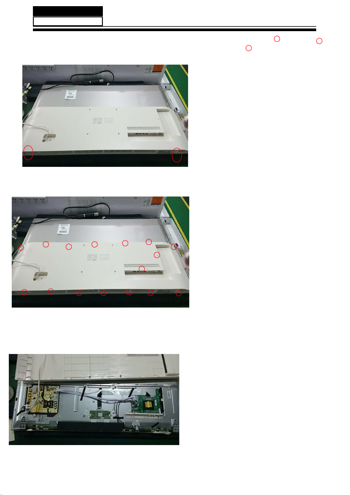
4-2Remove the Back Cover
/D\ GRZQ WKH XQLW VR WKDW UHDU FRYHU
faces upward
5HPRYH WKH WKUHH VFUHZ IURP WKH
UHDU FRYHU LQGLFDWHG ZLWK ż
7KHQ UHPRYH WKH SHGHVWDO
4-3. Remove the adhesive tape
5HPRYH WKH
¿JXUH DERYH E\ ż
7KHQ UHPRYH WKH EDFN FRYHU IURP WKH
unit.
Remove the adhesive tape indicated on the
WKHVH VFUHZ LQGLFDWHG RQ
- 14 -
¿JXUH DERYH
Page 16
LE49U6500DUA
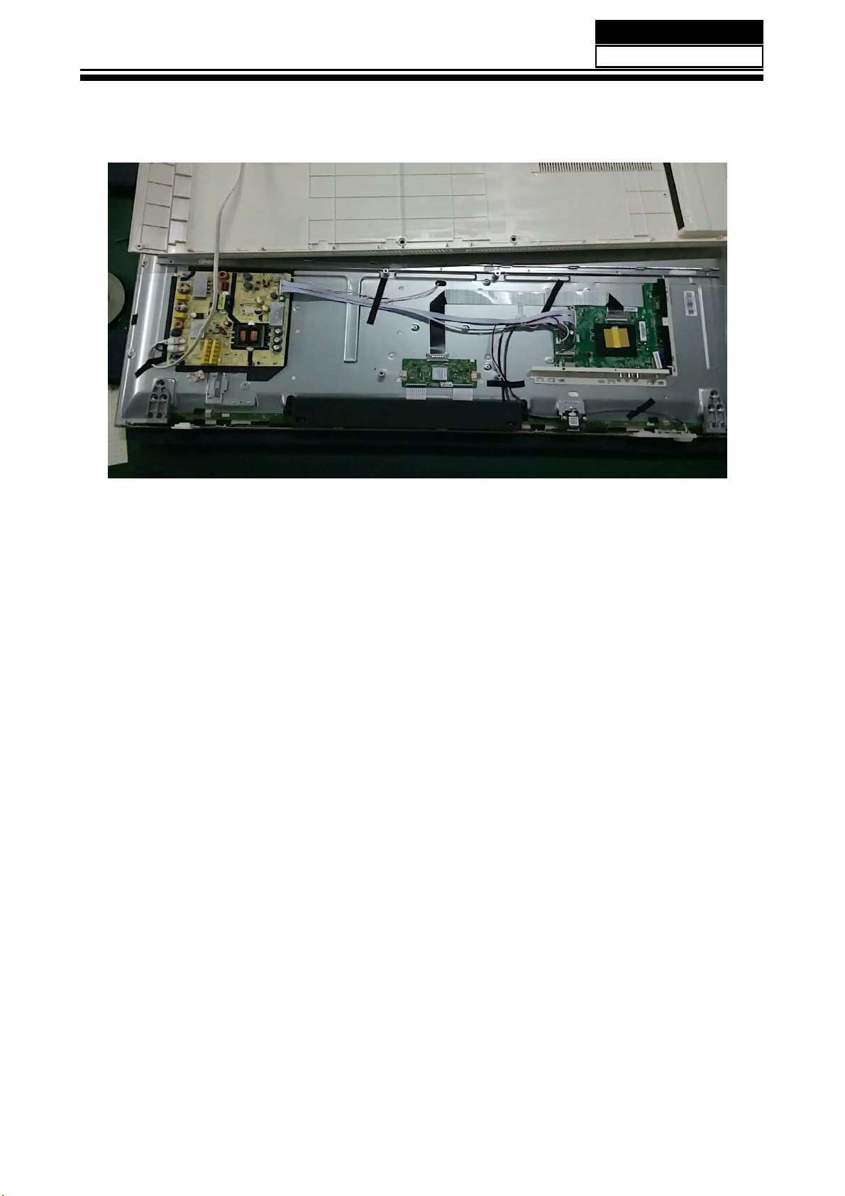
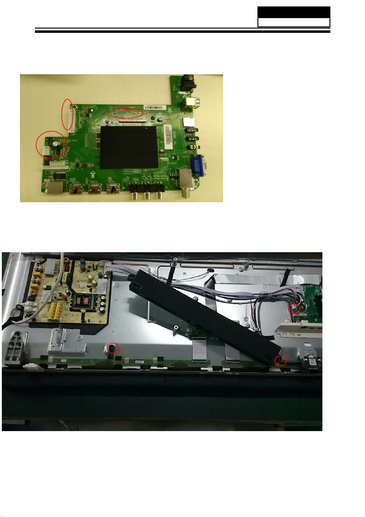
4-4 Remove the Main board
Service Manual
Model No.:
4-5 Remove the speaker
'LVFRQQHFWHG WKH
J2 J25 J20 P501
5HPRYH WKH 0DLQ ERDUG
FRXSOHU
Take out the speaker
- 15 -
Page 17

Service Manual
Model No.:
4-6 Remove the remote control
take out the Remote Control and Keypad Assembly
4-7 Remove the Power Supply
- 16 -
Page 18

5. Installation Instructions
5-1 External Equipment Connections
A
Service Manual
Model No.:
Battery
Remote Control
Antenna Connection
Connect one end of a coaxial cable (not included) to the ANT IN jack on the back of
your TV/DVD combo, then connect the other end of the cable into the antenna or cable
TV wall outlet.
Remote Control
To improve picture quality from an antenna in a poor signal area, install a signal
DPSOL¿HU
If you need to split the antenna signal to connect two TVs, install a two-way splitter.
- 17 -
Page 19

ANTENNA
PC
INSTALLATION
- 18 -
Page 20

* Subject to material object.
SUPPORTED MODE (PC)
1
RESOLUTION
640*480
V.Freq.(Hz) H.Freq.(KHz)
60
31.47
INSTALLATION
2
3
4
5
6
800*600
1024*768
1366*768
1280*1024
1920*1080
(Only for 40")
NOTE: PC V.Freq.(Hz) not more than 60Hz.
PRESET MODE (HDMI)
1
2
3
4
5
RESOLUTION
800*600
1024*768
1366*768
1280*768
1920*1080
60
60
60
60
60
V.Freq.(Hz) H.Freq.(KHz)
60
60
60
60
60
37.88
48.36
47.71
63.98
67.5
37.88
48.36
47.71
47.3
67.5
- 19 -
Page 21

AV EQUIPMENT
This TV provides one group of AV, one group of YPbPr for convenient connection to VCR, DVDor other
video equipment. Please refer to the owner's manual of the equipment to be connected as well.
You can use the input terminals on TV set rear as follows.
- 20 -
Page 22

Service Manual
Model No.:
5-2 HDMI Connections
When the source device(DVD player or Set Top Box) supports HDM
How T
1. Connect the source device to HDMI port of this TV with an HDMI cable(not supplied
with this product).
2. No separated audio connection is necessary.
How To Use
If the source device supports Auto HDMI function, the output resolution of the source
device will be automatically
set to 1280x720p.
If the source device does not support Auto HDMI, you need to set the output resolution
appropriately.
To get the best picture quality, adjust the output resolution of the source device to
1280x720p.
Select HDMI input source in input source option of Select Main source menu.
o Connect
When the source device(DVD player or Set Top Box) supports DVI
How To Connect
1. Connect the source device to HDMI port of this TV with a HDMI-to-DVI cable(not
supplied with this product).
2. A separated audio connection is necessary.
3. If the source device has an analog audio output connector, connect the source device
audio output to DVI Audio In port located on the PC port.
How To Use
If the source device supports Auto DVI function, the output resolution of the source device
will be automatically
set to 1280x720p.
If the source device does not support Auto DVI, you need to set the output resolution
appropriately.
To get the best picture quality, adjust the output resolution of the source device to
1280x720p.
Press the INPUT button to select HDMI input source in input source option of Select Main
source menu.
Installation
- 21 -
Page 23

Cable sample
Service Manual
Model No.:
HDMI Cable
(not supplied with the product)
HDMI to DVI Cable
( not supplied with the product)
Analog Audio Cable
(Stereo to RCA
(not supplied with the product)
type)
- 22 -
Page 24

Service Manual
Model No.:
Power source
TO USE AC POWER SOURCE
Use the AC polarized line cord provided for operation on AC.
Insert the
NOTES:
Ŷ 1HYHU FRQQHFW WKH $& OLQH FRUG SOXJ WR RWKHU WKDQ WKH VSHFL¿HG YROWDJH
Use the attached power cord only.
Ŷ ,I WKH SRODUL]HG $& FRUG GRHV QRW ¿W LQWR D QRQSRODUL]HG $& RXWOHW
GR QRW DWWHPSW WR ¿OH RU FXW WKH EODGH ,W LV WKH XVHUCV UHVSRQVLELOLW\ WR KDYH DQ
electrician replace the obsolete outlet.
Ŷ ,I \RX FDXVH D VWDWLF GLVFKDUJH ZKHQ WRXFKLQJ WKH XQLW DQG WKH XQLW IDLOV WR IXQFWLRQ
simply unplug the unit from the AC outlet and plug it back in. The unit should return to
normal operation.
AC cord plug into a standard polarized AC outlet.
- 23 -
Page 25

6. Operation Instructions
6-1 Front panel controls
Service Manual
Model No.:
Front panel
KEYBOARD
Rear/Side Sockets
- 24 -
Page 26

TELETEXT
Teletext is an information system broadcast by certain channels which can be consulted like
a newspaper. It also offers access to subtitles for viewers with hearing problems or who are
not familiar with the transmission language(cable networks, satellite channels, etc.)
Remote Control
Press:
TEXT
SELECTING A PAGE
DIRECT ACCESS
TO THE ITEMS
INDEX
SUB PAGE
HOLD
You will obtain :
This is used to call or exit teletext modes. The summary appears with a list
of items that can be accessed. Each item has a corresponding 3 digit page
number. If the channel selected does not broadcast teletext, the indication
100 will be displayed and the screen will remain blank (in this case, exit
teletext and select another channel).
Enter the number of the page required using the 0 to 9 up/down. Example:
page 120, enter 120. The number is displayed top left, the counter turns and
then the page is displayed. Repeat this operation to view another page. If
the counter continues to search, this means that the page is not
transmitted. Select another number.
Coloured are as are displayed at the bottom of the screen. The 4 coloured
keys are used to access the items or corresponding pages. The coloured
areas flash when the item or the page is not yet available.
This returns to the contents page (usually page 100).
Certain pages contain sub-pages which are automatically displayed
successively. This key is used to stop or resume sub-page acquisition.
The indication appears top left.
To freeze the page.
REVEAL
MIX
EXIT
SIZE
To display or hide the concealed information (games solutions).
Teletext,program,image are displayed together.
Exit the te le t ex t.
Swi tch t he ima ge to top, botto m,ful l.
EN-18
Page 27

5
D D
3
2
1
5V_Standby_0.85A 5V_Normal_2.06A
5V_Standby 5V_Normal 12V_Normal
5V_Standby_0.85A
5V_Normal_2.06A
12V_Normal_3.5A
12V_Normal_3.5A
MOS
GV3401
V_Panel_1.5A12V_Normal_1.5A
ON/OFF
12V_Normal_2A AMP
C C
5V_Normal_0.5A
MOS
GV3401
Cl_0.5A
AD82587
DC
MSH6110
DC
RT7240
2*8W12V_Normal_1.5A
VDDC_CPU_1.05V_1.6A12V_NORMAL_0.16A
VDDC 0.96V 3.8A12V NORMAL 0.38A
ON/OFF
5V_Normal_0.3A TUNER_0.3A
B B
LDO
1117-3.3
FUSE5V_Normal_1A 5V_USB_1A
1.5A
MSD6586
5V_Normal_0.26A
1117-3.3
3.3V_Normal_0.26ALDO
5V Standy 0.15A
DC
RT8097C
1117-3.3
1.5V_1.5A5V_Standy_0.5A
3.3V Standby 0.15ALDO
WIFI5V_Standby_0.2A
A A
Title
Title
Title
01. Power_Tree
01. Power_Tree
01. Power_Tree
Size Document Number Rev
Size Document Number Rev
Size Document Number Rev
<Doc> <RevCode>
A3
<Doc> <RevCode>
A3
<Doc> <RevCode>
A3
Date Sheet of
Date Sheet of
5
3
2
Date Sheet of
1 13Thursday, March 30, 2017
1 13Thursday, March 30, 2017
1 13Thursday, March 30, 2017
1
Page 28

5
+12V_Normal
J26
1
2
3
4
5
6
D D
7
8
9
10
1*10P*2.54mm/180
J27
1
2
3
4
5
6
1*6P*2.0mm/180
STANDBY
BL-ADJUST
BL-ON/OFF
+5V_Normal
Vcc_Panel
+5V_Standby
+12V_Normal
VDDC_CPU Power
+12V_Normal
R120
100K
C125
C124
靠近
DCDC
10uF/16V/X5R
R123 10K
C126
0.1uF/16V/X5R
0.1uF/16V/X5R
C127
0.1uF/16V/X5R
4
U104
MSH6110A
Addr 0x80
8
PVDD
1
EN
3
5V
4
SDA
I2C-SDA 3,7,13
LX
BST
FB
SCL
PowerPAD
9
D101
L102
2.2uH/6A/不涂胶
NC/SS34
6
C118
7
0.1uF/16V/X5R
2
R2=50K
5
Vout=0.828V*(1+R1/50K)
有
DVFS
R1
I2C-SCL 3,7,13
功能,此
12
DCDC
R122
C119
NC
330pF
R124 15K/1%
不能更改
R124:
538
和
Note
:能提供最大平均电流5A。
远端反馈,即 从
IC
3
6586
统一为
+1.05_VDDC_CPU
底部引线
C120
2
15K
22uF/6.3V/X5R
C121
+1.05_VDDC_CPU
C123
C122
靠近
DC-DC
22uF/6.3V/X5R
0.1uF/16V/X5R
NC/22uF/6.3V/X5R
1
Control
BL-ADJUST
BL-ON/OFF
C C
STANDBY
C117
R119
10K
R126 100R
R117 1K
R118 1K
R121
10K
2.2uF/6.3V/X5R/NC
+5V_Standby
H :Power on
R125
L :Power off
4.7K
PWR-ON/OFF 3
BRI_ADJ 3
VBL_CTRL 3
VDDC Power
R6856 100K
C2245
C2247
C2248
R6944
NC
10uF/16V/X5R
10uF/16V/X5R
0.1uF/16V/X5R
C2178
U11
RT7240
VCC8SW
1
EN
3
VREG5
C29
C30
3900pF
1uF/10V/X5R
0.1uF/16V/X5R
BST
4
SS
5
FB
GND
9
GND
6
7
2
L17
1 2
C31
0.1uF/16V/X5R
C217910pF/NC
R1
RW225.6K/1%
RW2521K/1%
R2
2.2uH/6A/不涂胶
C2261 220uF/10V/X5R/LowESR
470R/1%
R106
远端反馈,即 从
0.96V
C105
+1.10V_VDDC
C106
IC
+1.10V_VDDC+12V_Normal
C107
底部引线
C108
22uF/6.3V/X5R
22uF/6.3V/X5R
22uF/6.3V/X5R/NC
0.1uF/16V/X5R
靠近
DC-DC
Vout=0.765V*(1+R1/R2)=0.979V
Connector
1*13P*2.54mm/180/NC
+12V_Normal
13
12
11
10
9
8
7
6
5
STANDBY
4
3
BL-ON/OFF
2
BL-ADJUST
1
J20
+5V_Normal
+5V_Standby
H :Power on
L :Power off
+5V_Normal
LDO
2
U103
ADJ
+5V_Normal
0.1uF/16V/X5R
4
OUT
IN
321
+3.3V_Normal
C116
C115
C114
10uF/6.3V/X5R
0.1uF/16V/X5R
Title
Title
Title
02. System power
02. System power
02. System power
Size Document Number Rev
Size Document Number Rev
Size Document Number Rev
<Doc> <RevCode>
Custom
<Doc> <RevCode>
Custom
<Doc> <RevCode>
Custom
Date: Sheet of
Date: Sheet of
Date: Sheet of
+5V_Normal
4
U1111117-1.8V
ADJ
OUT
IN
321
+1.8V_Normal
C2260
C162
C163
10uF/6.3V/X5R
0.1uF/16V/X5R
40mA
1
0.1uF/16V/X5R
2 13Thursday, March 30, 2017
2 13Thursday, March 30, 2017
2 13Thursday, March 30, 2017
L103
2.2uH/2.2A
R6953 10K
C131 22pF/NC
R129 15K/1%
R130 5.1K/1%
R2
R69434.7K/1%
12
SW3VIN
POK
FB
GND
JW5212SOTB
5
R1
6
Vout=0.6V*(1+R1/R2)=1.518V
H3
1
2
金属支架
4
Note
:能提供最大平均电流2A。
C132
22uF/6.3V/X5R
+12V_Normal
R6954
R6955
0R/NC
0R/NC
C133
靠近
22uF/6.3V/X5R/NC
+1.5V_DDR
DCDC
R6956
0R/NC
C134
0.1uF/16V/X5R
3
H115
NC
+5V_Standby
C135
C2240
靠近
10uF/10V/X5R
10uF/10V/X5R
RT8097C 2A
1
输入耐压值
C136
DCDC
B B
TP & MARK
1
H104
NC
H108
NC
H113
NC
1
H105
H106
NC
NC
1
1
H110
H109
NC
NC
H1
NC
1
1
5
1
1
H101
NC
1
1
H107
NC
H117
NC
A A
H120
NC
1
1
U106
5.5V
4
1
EN
H118
金属支架
1
2
2
H2
金属支架
0.1uF/16V/X5R
1
2
1117-3.3V
+5V_Standby
U102
ADJ
0.1uF/16V/X5R
4
OUT
IN
321
+3.3V_Standby
C110
C111
C112
10uF/6.3V/X5R
0.1uF/16V/X5R
1117-3.3V
Page 29

HDMI/Audio Block GPIO Pull up
5
Note : Port A needs shielding ground all signal pair
HDMI1-RX0N9
HDMI1-RX0P9
HDMI1-RX1N9
HDMI1-RX1P9
HDMI1-RX2N9
HDMI1-RX2P9
HDMI1-CLKN9
HDMI1-CLKP9
HDMI1-SCL9
HDMI1-SDA9
HDMI1-HPD9
HDMI-CEC9
HDMI1-Detect9
D D
HDMI2-RX0N9
HDMI2-RX0P9
HDMI2-RX1N9
HDMI2-RX1P9
HDMI2-RX2N9
HDMI2-RX2P9
HDMI2-CLKN9
HDMI2-CLKP9
HDMI2-SCL9
HDMI2-SDA9
HDMI2-HPD9
HDMI2-Detect9
HDMI3-RX0N9
HDMI3-RX0P9
HDMI3-RX1N9
HDMI3-RX1P9
HDMI3-RX2N9
HDMI3-RX2P9
HDMI3-CLKN9
HDMI3-CLKP9
HDMI3-SCL9
HDMI3-SDA9
HDMI3-HPD9
HDMI3-Detect9
C C
RGB/CVBS/PHY/USB Block
VGA_HSYNC8
VGA_VSYNC8
SCART_RIN+8
SCART_GIN+8
SCART_BIN+8
YPBPR_PR8
YPBPR_PB8
B B
Crystal
XTALO
XTALI
NOTE:
Config
+3.3V_Standby
A A
R240 4.7K
R245 4.7K
R247 4.7K
R250 4.7K
CHIP_CONFIG[3:0]
{PAD_PM_LED1,PAD_PM_SPI_DI,PAD_PM_LED0,PAD_PWM_PM}
Value Description
4'b1010 1 ARM boot from ROM; outer storage is eMMC
4'b1011 ARM boot from ROM; outer storage is NAND
VGA_RIN+8
VGA_GIN+8
VGA_BIN+8
YPBPR_Y8
SC-FS8
SC-FB8
AV_IN8
SC_AV8
晶体频偏需要小于
C1=C2=2*CL-5
U201C
N3
RXA0N
N2
RXA0P
P3
RXA1N
P2
RXA1P
P1
RXA2N
R3
RXA2P
M1
RXACKN
M2
RXACKP
R2
DDCDA_CK
T3
DDCDA_DA
T2
HOTPLUGA
P5
CEC
U3
HOTPLUGA_HDMI20_5V
J2
RXB0N
K3
RXB0P
K2
RXB1N
L3
RXB1P
L2
RXB2N
L1
RXB2P
J3
RXBCKN
J1
RXBCKP
N5
DDCDB_CK
N6
DDCDB_DA
R4
HOTPLUGB
P4
HOTPLUGB_HDMI20_5V
B1
RXC0N
C1
RXC0P
C2
RXC1N
D3
RXC1P
D2
RXC2N
E3
RXC2P
A2
RXCCKN
B2
RXCCKP
M5
DDCDC_CK
L6
DDCDC_DA
J4
HOTPLUGC
H4
HOTPLUGC_HDMI20_5V
F1
RXD0N
F2
RXD0P
G3
RXD1N
G2
RXD1P
H3
RXD2N
H2
RXD2P
E1
RXDCKN
F3
RXDCKP
K5
DDCDD_CK
L5
DDCDD_DA
M6
HOTPLUGD
L4
HOTPLUGD_HDMI20_5V
MSD6A538
R222 33R
R223 68R
R224 33R
R225 33R
VGA_HSYNC
VGA_VSYNC
R226 33R/NC
R227 68R/NC
R228 33R/NC
R229 33R/NC
R230 33R
R231 68R
R232 33R
R233 33R
R234 68R
R1761 33R
R235 33R
AV_OUT8
C237 33pF
12
C1
Y201
24MHz/20pF
C2
C238 33pF
30PPM
PM_LED1
SPI-SDI
PM_LED0
PM_PWM
Y3
C201 2.2uF/6.3V/X5R
LINE_IN_0L
Y2
C206 2.2uF/6.3V/X5R
LINE_IN_0R
Y1
C207 2.2uF/6.3V/X5R
LINE_IN_2L
AA3
C208 2.2uF/6.3V/X5R
LINE_IN_2R
AB5
LINE_OUT_0L
AB6
AV_OUT
C222
C223
C224
C225
C226
C227
C228
C229
C230
C231
C232
C233
C234
C1333
C235
HDMI
0.047uF/16V/X7R
0.047uF/16V/X7R
0.047uF/16V/X7R
0.047uF/16V/X7R
0.047uF/16V/X7R/NC
0.047uF/16V/X7R/NC
0.047uF/16V/X7R/NC
0.047uF/16V/X7R/NC
0.047uF/16V/X7R
0.047uF/16V/X7R
0.047uF/16V/X7R
0.047uF/16V/X7R
0.047uF/16V/X7R
0.047uF/16V/X7R
0.047uF/16V/X7R
C236
NC/120pF
VCOM
CVBS0
CVBS1
RIN0
GIN0N
GIN0
BIN0
RIN1
GIN1N
GIN1
BIN1
RIN2
GIN2N
GIN2
BIN2
Analog
Audio
I2S
SPDIF
V1
V3
U1
U2
P6
R5
U6
V6
V4
V5
Y6
Y5
W6
W5
T6
R6
V2
T5
U4
U5
EARPHONE_OUT_L
EARPHONE_OUT_R
I2S_OUT_BCK
I2S_OUT_MCK
I2S_OUT_SD1
I2S_OUT_SD2
U201E
RIN0P
GIN0M
GIN0P
BIN0P
HSYNC0
VSYNC0
RIN1P
GIN1M
GIN1P
BIN1P
RIN2P
GIN2M
GIN2P
BIN2P
HSYNC1
VSYNC1
VCOM
CVBS0
CVBS1
CVBSOUT1
MSD6A538
LINE_OUT_0R
LINE_OUT_2L
LINE_OUT_2R
I2S_OUT_WS
AUVAG
AUVRM
I2S_OUT_SD
SPDIF_IN
SPDIF_OUT
RGB
CVBS
AV_LOUT
AC5
AV_ROUT
AC6
HP_Audio-L
AD5
HP_Audio-R
AD6
M4
ARC0
AA2
AUVAG
AA1
AUVRM
T21
NC
R20
NC
R21
NC
AUBCK_OUT
E6
AUMCK_OUT
E5
AUWS_OUT
F4
AUSD_OUT
F6
F5
G5
3D_FLAG
K6
SPDIF_OUT
J5
PHY
GPIO19/LED[0]
GPIO20/LED[1]
USB
USB_DM_PSS
USB3.0
USB_DP_PSS
IR&KEY
+3.3V_Standby+5V_Standby
R212
R213
47K
4.7K
C215
100pF
J2
14
13
12
11
10
9
8
7
6
5
4
3
2
1
1*14P*2.0mm/180
CON14
IR-IN_1
+5V_Standby
LED_RED#
LED_GRE#
MENU
SOURCE
PP+
VV+
KEY7
POWER
IR-in
R215 100R
C212
33pF
KEY0-in KEY0
R218 1K
+5V_Standby
C2259
0.1uF/16V/X5R
5
YPBPR_AUL 8
YPBPR_AUR 8
SC_PC_AUL 8
SC_PC_AUR 8
HDMI-ARC 9
1
TP212
SPDIF_OUT 8
B3
TN
A3
TP
B4
RN
C4
RP
R27
R26
L27
HWRESET
AG1
XIN
AF1
XOUT
AE5
IRIN
B7
USB0_DM
C7
USB0_DP
B6
USB1_DM
A6
USB1_DP
C6
USB2_DM
A5
USB2_DP
AF7
NC
AG7
NC
AG8
AH8
AH9
NC
AG9
NC
538/6586
预留的线路可以删除
LED_RED#
LED_GRE#
IR-IN_1
4
Audio Block
AV_LOUT
AV_ROUT
HP_Audio-L
HP_Audio-R
Close to MST IC
with width trace
MDI_TN
MDI_TP
MDI_RN
MDI_RP
System-RST
XTALI
XTALO
IR-in
都不支持
+5V_Normal
R639
Q601
32
1
SOT-23
KEY0
4
AUVAG
AUVRM
R642
R641
4.7K
1K
3904
20K
靠近
mstar IC
C204
C209
MDI_TN 8
MDI_TP 8
MDI_RN 8
MDI_RP 8
USB2_D- 11
USB2_D+ 11
USB1_D- 11
USB1_D+ 11
USB3_D- 11
USB3_D+ 11
USB3.0
R21
R22
R25
R26
R28 82K/1%
R31 47K/1%
R34
R35
AV_LOUT 8
AV_ROUT 8
C205
1000pF
1000pF
EARPHONE_OUTL 13
EARPHONE_OUTR 13
C210
10uF/6.3V/X5R
0.1uF/16V/X5R
L201
1000R/FBI
!
LED_R
POWER
MENU
SOURCE
V+
V-
P+
P-
KEY7
PCMCIA/TS/NAND/FE
PCM_D[7:0]12
PCM_D0
PCM_D1
PCM_D2
PCM_D3
PCM_D4
PCM_D5
PCM_D6
PCM_D7
PCM_A[14:0]12
PCM_A0
PCM_A1
PCM_A2
PCM_A3
PCM_A4
PCM_A5
PCM_A6
PCM_A7
PCM_A8
PCM_A9
PCM_A10
PCM_A11
PCM_A12
PCM_A13
PCM_A14
SD_CLK
SD_CLK
SD_CMD
SD_CMD
PCM_IRQA_N
PCM_IRQA_N12
PCM_OE_N
PCM_OE_N12
PCM_IORD_N
PCM_IORD_N12
PCM_CE_N
PCM_CE_N12
PCM_WE_N
PCM_WE_N12
PCM_CD_N
PCM_CD_N12
PCM_RESET
PCM_RESET12
PCM_REG_N
PCM_REG_N12
PCM_IOWR_N
PCM_IOWR_N12
PCM_WAIT_N
PCM_WAIT_N12
NAND-CEZ
NAND-CEZ6
NAND-REZ
NAND-REZ6
NAND-RBZ
NAND-RBZ6
NAND-DQS
NAND-DQS6
NAND-AD[7:0]6
NAND-AD0
NAND-AD1
NAND-AD2
NAND-AD3
NAND-AD4
NAND-AD5
NAND-AD6
NAND-AD7
LVDS/GPIO
BRI_ADJ
BRI_ADJ2
LR_SYNC
LR_SYNC7
KEY0-in
PANEL_ON/OFF
PANEL_ON/OFF7
WIFI-reset11
POWER_DETECT
SPI-SDI
UART-RX
R236 100R
UART-RX8
UART-TX
R237 100R
UART-TX8
HP_DET
HP_DET13
AMP_RST
R1823 0R
AMP_RST13
I2C-SCL
I2C-SDA
WOW_WOL11
R1819 100R
R238 100R
R239 100R
0R
7.5K/1%
16.9K/1%
150K/1%
30K/1%
0R
SC_PC_SW8
3
U201B
AC25
PCMDATA[0]/CI_DATA[0]
AG23
PCMDATA[1]/CI_DATA[1]
AB25
PCMDATA[2]/CI_DATA[2]
AD25
PCMDATA[3]/CI_DATA[3]
AC24
PCMDATA[4]/CI_DATA[4]
AC23
PCMDATA[5]/CI_DATA[5]
AD24
PCMDATA[6]/CI_DATA[6]
AD23
PCMDATA[7]/CI_DATA[7]
AE24
PCMADR[0]/CI_A[0]
AE23
PCMADR[1]/CI_A[1]
AC22
PCMADR[2]/CI_A[2]
AD22
PCMADR[3]/CI_A[3]
AC21
PCMADR[4]/CI_A[4]
AG22
PCMADR[5]/CI_A[5]
AD21
PCMADR[6]/CI_A[6]
AC20
PCMADR[7]/CI_A[7]
AC19
PCMADR[8]/CI_A[8]/SDIO_D0
AF21
PCMADR[9]/CI_A[9]/SDIO_D1
AD20
PCMADR[10]/CI_A[10]/SDIO_D2
AD19
PCMADR[11]/CI_A[11]/SDIO_D3
AD18
PCMADR[12]/CI_A[12]
AE18
PCMADR[13]/CI_A[13]
AE20
PCMADR[14]/CI_A[14]
AB24
PCM2_CE_N/SDIO_CLK
AB23
PCM2_IRQA_N/SDIO_CMD
AE17
PCMIRQA/CI_INT
AE21
PCMOEN
AG21
PCMIORD/CI_RD
AC18
PCMCEN/CI_CS
AD17
PCMWEN
AH21
PCMCD/CI_CD
AC16
PCMRST/CI_RST
AF22
PCMREG/CI_CLK
AC17
PCMIOWR/CI_WR
AD16
PCMWAIT/CIWACK
AC13
NAND_ALE/EMMC_IO15
AD12
NAND_WPZ/EMMC_IO17
AG11
NAND_CEZ/EMMC_IO9/EMMC_CMD
AC12
NAND_CLE/EMMC_IO14
AF11
NAND_REZ/EMMC_IO10/EMMC_CLK
AD13
NAND_WEZ/EMMCIO16
AG10
NAND_RBZ/EMMC_IO11/EMMC_RSTn
AE12
NAND_CEZ1/EMMC_IO12
AD14
NAND_DQS/EMMC_IO8
AG15
NAND_AD0/EMMC_IO6/EMMC_D[6]
AH15
NAND_AD1/EMMC_IO7/EMMC_D[7]
AH14
NAND_AD2/EMMC_IO2/EMMC_D[2]
AG14
NAND_AD3/EMMC_IO1/EMMC_D[1]
AG13
NAND_AD4/EMMC_IO0/EMMC_D[0]
AF13
NAND_AD5/EMMC_IO3/EMMC_D[3]
AH12
NAND_AD6/EMMC_IO4/EMMC_D[4]
AF12
NAND_AD7/EMMC_IO5/EMMC_D[5]
MSD6A538
P27
R28
N28
PM_PWMLED_R
AF6
AD10
AC10
N27
M26
M27
M28
AC15
AD15
AF16
AG16
AC11
3D_EN
AD11
P26
N26
VID_0
AB2
VID_1
AB3
AA4
PM_LED0
AD4
PM_LED1
AC4
AE11
3
U201D
PWM0
PWM1
PWM2
T22
NC
PWM_PM
D4
SAR0
D5
SAR1
C5
SAR2
B5
SAR3
E4
SAR5/PW_det
G6
SPI_CK
H6
SPI_DI
H5
SPI_DO
J6
SPI_CZ1/GPIO_PM6
DDCA_CK/UART0_RX
DDCA_DA/UART0_TX
GPIO2/EJ_TCK
GPIO3/EJ_TMS
GPIO4/EJ_TDI
GPIO5/EJ_TDO
GPIO9/TX2
GPIO10/RX2
GPIO11/TX3
GPIO12/RX3
GPIO30/SCK4
GPIO31/SDA4
DDCR_CK
DDCR_DA
VID0
VID1
VID2
Y4
VID3
LED0
LED1
WOL
MSD6A538
CI
PCMCIA
PWM
SAR
SPI
GPIO
/UART
I2C
NAND
EMMC
PM_UART
TS2
(In)
TS0
(In)
TS1
(In/Out)
Front
End
LVDS
60Hz
PM
TS2DATA [0]
TS2CLK
TS2VALID
TS2SYNC
TS0DATA_[0]
TS0DATA_[1]
TS0DATA_[2]
TS0DATA_[3]
TS0DATA_[4]
TS0DATA_[5]
TS0DATA_[6]
TS0DATA_[7]
TS0CLK
TS0VALID
TS0SYNC
TS1DATA_[0]
TS1DATA_[1]
TS1DATA_[2]
TS1DATA_[3]
TS1DATA_[4]
TS1DATA_[5]
TS1DATA_[6]
TS1DATA_[7]
TS1CLK
TS1VALID
TS1SYNC
IFAGC_T
TGPIO0
TGPIO1
TGPIO2
TGPIO3
IFAGC_S
GPIO15/DiSEqC_out
GPIO18/DiSEqC_in
B0M (R_ODD[7])
B0P (R_ODD[6])
B1M (R_ODD[5])
B1P (R_ODD[4])
B2M (R_ODD[3])
B2P (R_ODD[2])
BCKM (R_ODD[1])
BCKP (R_ODD[0])
B3M (G_ODD[7])
B3P (G_ODD[6])
B4M (G_ODD[5])
B4P (G_ODD[4])
A0M (G_ODD[3])
A0P (G_ODD[2])
A1M (G_ODD[1])
A1P (G_ODD[0])
A2M (B_ODD[7])
A2P (B_ODD[6])
ACKM (B_ODD[5])
ACKP (B_ODD[4])
A3M (B_ODD[3])
A3P (B_ODD[2])
A4M (B_ODD[1])
A4P (B_ODD[0])
GPIO_PM4/PW_ctrl
GPIO_PM1/PM_TX1
GPIO_PM5/PM_RX1
IP_T
IM_T
SIFP
SIFM
IP_S
IM_S
QP_S
QM_S
LVSYNC
LHSYNC
GPIO_PM0
GPIO_PM3
GPIO_PM7
GPIO_PM8
2
M24
N24
N25
P25
TS_MDO[7:0] 12
TS_MDO0
AH20
TS_MDO1
AG20
TS_MDO2
AF17
TS_MDO3
AH18
TS_MDO4
AG17
TS_MDO5
AF20
TS_MDO6
AG18
TS_MDO7
AF18
TS_MOCLK
AF19
AH17
AG19
U23
T25
N23
P23
U24
T23
R25
R24
R23
P24
T24
AC2
AC3
AD1
AD2
AC1
AD3
AE2
AF3
AE4
AH2
AH3
AF4
AG3
AG4
AG5
AF5
TS_MOVLD
TS_MOSYNC
TS_D0
TS_D1
TS_D2
TS_D3
TS_D4
TS_D5
TS_D6
TS_D7
TS_CLK
TS_VLD
TS_SYNC
C216
C217
IFAGC
T_SCL
T_SDA
0.1uF/16V/X5R
DIFP
DIFM
0.1uF/16V/X5R
TS_MOCLK 12
TS_MOVLD 12
TS_MOSYNC 12
TS_D[7:0] 12
TS_CLK 12
TS_VLD 12
TS_SYNC 12
IFAGC
R217 0R
DIFP 10
DIFM 10
T_SCL 3,10
T_SDA 3,10
R216 10K
+3.3V_TU
IF_AGC 10
C213
0.022uF/16V/X7R
AMP-MUTE13
I2S out
AUBCK_OUT13
AUMCK_OUT13
AUSD_OUT13
AUWS_OUT13
3D_LR_in
3D_LR_in 7
3D_EN
3D_EN 3,7
I2C-SCL
I2C-SCL 2,7,13
I2C-SDA
I2C-SDA 2,7,13
Heat Sink
S201
Heat-sink-62X70X2.3
R6957
0R/NC
1
VID_0
VID_1
I2C-SCL
I2C-SDA
3D_EN
3D_EN3,7
T_SCL
T_SCL3,10
T_SDA
T_SDA3,10
AUBCK_OUT
AUMCK_OUT
AUSD_OUT
AUWS_OUT
1
2
+3.3V_Standby
R202 4.7K
R204 4.7K
R205 4.7K
+3.3V_Normal
R206 4.7K
R207 4.7K
R208 4.7K
+3.3V_TU
R209 4.7K
R210 4.7K
I2C-SDA2,3,7
I2C-SCL2,3,7
C2262
C2263
100pF/NC
R6958
0R/NC
100pF/NC
RESET
T27
U27
LCK
U26
LDE
T28
V27
B0M
V28
B0P
W28
B1M
W27
B1P
Y27
B2M
AA26
B2P
AA28
BCKM
AB26
BCKP
AB27
B3M
AC26
B3P
AD26
B4M
AD27
B4P
AE26
A0M
AE28
A0P
AF26
A1M
AF27
A1P
AG27
A2M
AG28
A2P
AH27
ACKM
AH26
ACKP
AF25
A3M
AG25
A3P
AG24
A4M
AH24
A4P
AE6
W2
W3
AA5
AA6
PM_TX
AH6
PM_RX
AH5
P21
TEST
2
AMP-MUTE
SD_WP
3D_LR_IN 7
B0M 7
B0P 7
B1M 7
B1P 7
B2M 7
B2P 7
BCKM 7
BCKP 7
B3M 7
B3P 7
B4M 7
B4P 7
A0M 7
A0P 7
A1M 7
A1P 7
A2M 7
A2P 7
ACKM 7
ACKP 7
A3M 7
A3P 7
A4M 7
A4P 7
VBL_CTRL 2
BT_WAKE 2
PWR-ON/OFF 2
SD_CDZ
+5V_Standby
C239
4.7uF/10V/X5R
System-RST
3
D201
R251
BAT54C
100K
1
2
UART
CN206
1*4P*2.0mm/180/NC
1
2
UART-RX
3
UART-TX
4
+12V_Normal
R244
1K
R252
10K
POWER_DETECT
R257
1K
Title
Title
Title
03. MSD6A538/6586
03. MSD6A538/6586
03. MSD6A538/6586
Size Document Number Rev
Size Document Number Rev
Size Document Number Rev
<Doc> <RevCode>
Custom
<Doc> <RevCode>
Custom
<Doc> <RevCode>
Custom
Date: Sheet of
Date: Sheet of
Date: Sheet of
R243 4.7K
R246 4.7K
1
+5V_Standby
3 13Thursday, March 30, 2017
3 13Thursday, March 30, 2017
3 13Thursday, March 30, 2017
Page 30

5
U201F
VDDP33
AVDD_PLL
MSD6A538
G7
VDDC
G8
VDDC
H7
VDDC
H8
VDDC
J7
VDDC
J8
VDDC
J9
VDDC
K7
VDDC
K8
VDDC
K9
VDDC
L7
VDDC
L8
VDDC
L9
VDDC
M9
VDDC
M8
VDDC
M7
VDDC
V18
VDDC_CPU
V19
VDDC_CPU
V20
VDDC_CPU
W18
VDDC_CPU
W19
VDDC_CPU
W20
VDDC_CPU
W21
VDDC_CPU
Y19
VDDC_CPU
Y20
VDDC_CPU
Y21
VDDC_CPU
Y22
VDDC_CPU
AA19
VDDC_CPU
AA20
VDDC_CPU
AA21
VDDC_CPU
AA22
VDDC_CPU
Y12
DVDD_NODIE
Y7
AVDD_NODIE
M10
DVDD_DDR
N9
DVDD_DDR
N10
DVDD_DDR
M14
AVDD_DDR_A
N14
AVDD_DDR_A
P14
AVDD_DDR_A
N15
AVDD_DDR_A
M15
AVDD_DDR_A
Y15
NC
AA15
NC
K12
AVDD_DDR_B
K13
AVDD_DDR_B
K14
AVDD_DDR_B
J12
AVDD_DDR_B
J13
AVDD_DDR_B
K21
AVDD_DDR_DRAM
K26
AVDD_DDR_DRAM
J27
AVDD_DDR_VBP_A
M13
AVDD_DDR_VBP_A_DM
K28
AVDD_DDR_VBN_A
N13
AVDD_DDR_VBN_A_DM
H27
NC
L13
NC
G28
NC
L12
NC
J14
AVDD_DDR_LDO_B
R10
AVDDL_MOD
T13
AVDDL_MOD
AH23
AVDDL_MOD
W15
AVDDL_MOD_CAP
J18
NC
K15
AVDD15_MOD
K16
AVDD15_MOD
AA14
AVDD_MOD
N7
AVDDL_MHL3
N8
AVDDL_MHL3
W10
AVDDL_MHL3_CAP
AA12
AVDD3P3_MHL3
AB12
AVDD3P3_MHL3
AA10
VDDP_3318_A
AB11
VDDP_3318_C
AE15
PADA_EMMC_CTRL
W7
AVDD3P3_DADC
AA9
AVDD3P3_DMPLL
W8
AVDD3P3_ETH
U7
AVDD3P3_USB
T7
AVDD3P3_USB
T8
AVDD3P3_USB3
V7
AVDD3P3_ADC
V8
AVDD3P3_ADC
U8
AVDD_AU33
U9
AVDD_EAR33
AB14
VDDP
AB15
VDDP
AA13
AVDD_LPLL
AB13
AVDD_LPLL
Y13
AVDD_PLL_A
Y14
AVDD_PLL_B
P22
GND_EFUSE
VDDC
D D
VDDC_CPU
DVDD_NODIE
C324
AVDD_NODIE
1uF/10V/X5R
DVDD_DDR
AVDD_DDR3_1V5
C C
B B
A A
NC/100nF
C345
NC/0.1uF
C342
C341
NC/100nF
C347
NC/0.1uF
C346
NC/0.1uF
AVDD_DDR3_1V5
AVDD_DDR3_1V5
AVDD_DDR_VBP_A_DM
AVDD_DDR_VBN_A_DM
AVDD_DDR_VBP_B_DM
AVDD_DDR_VBN_B_DM
AVDD_DDR_LDO_B
C357
AVDD3P3_MHL3
NC
AVDD_DDR
AVDDL_MOD
AVDD15_MOD
AVDD_MOD
AVDDL_MHL3
VDDP_NAND_A
VDDP_NAND_C
AVDD_DADC
AVDD_DMPLL
AVDD33_LAN
AVDD_USB
AVDD_USB3
AVDD33_ADC
AVDD_AU33
AVDD_LPLL
4
U201G
M16
A1
A8
A15
A17
A24
A26
A28
B9
B14
B16
B18
B23
B25
B27
C3
C8
C11
C12
C13
C20
C21
C22
D6
D7
D8
D9
D10
D12
D14
D16
D18
D20
D22
D24
D26
D28
E2
E7
E8
E9
E10
E11
E13
E15
E17
E19
E21
E23
E25
E27
F7
F8
F9
F10
G9
G10
G11
G12
G13
G14
G15
G16
G17
G18
G19
G20
G21
G22
G23
G24
G25
G27
H1
H9
H10
H11
H12
H13
H14
H15
H16
H17
H18
H19
H20
H21
H22
H23
H24
H25
J10
J11
J15
J16
J17
J19
J21
J22
J23
J25
J26
K10
K11
K17
K18
K19
K20
K22
K23
K24
K25
L10
L11
L14
L15
L16
L17
L18
L19
L20
L23
L24
MSD6A538
M22
M3
M12
M17
M18
M19
M20
M11
M21
GND
GND
GND
GND
GND
GND
GND
GND
GND
GND
GND
GND
GND
GND
GND
GND
GND
GND
GND
GND
GND
GND
GND
GND
GND
GND
GND
GND
GND
GND
GND
GND
GND
GND
GND
GND
GND
GND
GND
GND
GND
GND
GND
GND
GND
GND
GND
GND
GND
GND
GND
GND
GND
GND
GND
GND
GND
GND
GND
GND
GND
GND
GND
GND
GND
GND
GND
GND
GND
GND
GND
GND
GND
GND
GND
GND
GND
GND
GND
GND
GND
GND
GND
GND
GND
GND
GND
GND
GND
GND
GND
GND
GND
GND
GND
GND
GND
GND
GND
GND
GND
GND
GND
GND
GND
GND
GND
GND
GND
GND
GND
GND
GND
GND
GND
GND
GND
GND
GND
GND
GND
GND
GND
GND
GND
GND
GND
GND
GND
GND
GND
N21
N22
N16
N12
N17
N18
N19
N20
M23
N11
GND
GND
GND
GND
GND
P10
P8
GND
GND
GNDP7GND
GND
GND
GND
GND
GNDP9GND
GND
3
CORE Power
P13
P15
P12
P16
P18
P19
P20
P11
GND
GND
GND
GND
GND
GND
GND
R1
GND
R7
GND
R8
GND
R9
GND
R11
GND
R12
GND
R13
GND
R14
GND
R15
GND
R17
GND
R18
GND
R19
GND
T9
GND
T10
GND
T11
GND
T12
GND
T17
GND
T18
GND
T19
GND
T20
GND
T26
GND
U10
GND
U11
GND
U12
GND
U13
GND
U17
GND
U18
GND
U19
GND
U20
GND
U21
GND
U22
GND
V9
GND
V10
GND
V11
GND
V12
GND
V13
GND
V14
GND
V15
GND
V16
GND
V17
GND
V21
GND
V22
GND
V23
GND
V24
GND
V25
GND
V26
GND
W9
GND
W11
GND
W12
GND
W13
GND
W14
GND
W16
GND
W17
GND
W22
GND
W23
GND
W24
GND
W25
GND
W26
GND
Y8
GND
Y9
GND
Y10
GND
Y11
GND
Y16
GND
Y17
GND
Y18
GND
Y23
GND
Y24
GND
Y26
GND
AA7
GND
AA8
GND
AA11
GND
AA16
GND
AA17
GND
AA18
GND
AA23
GND
AA24
GND
AA25
GND
AA27
GND
AB7
GND
AB8
GND
AB9
GND
AB16
GND
AB17
GND
AB18
GND
AB19
GND
AB20
GND
AB21
GND
AB22
GND
AB28
GND
AC7
GND
AC8
GND
AC9
GND
AC14
GND
AC27
GND
AD7
GND
AD8
GND
AD9
GND
AD28
GND
AE3
GND
AE8
GND
AE9
GND
AE14
GND
AE27
GND
AF2
GND
AF8
GND
AF9
GND
AF10
GND
AF14
GND
AF15
GND
AF23
GND
AF24
GND
AG2
GND
AG6
GND
AG12
GND
AG26
GND
AH1
GND
AH11
GND
AH28
GND
+1.10V_VDDC
C309
C301
C0805
C0805
22uF/6.3V/X5R
22uF/6.3V/X5R/NC
+1.10V_VDDC VDDC
4200mA,100mil
180mA,25mil
+1.10V_VDDC AVDDL_MHL3
80mA,25mil
CPU Power
+1.05_VDDC_CPU
C329
C0805
22uF/6.3V/X5R
NC/22uF/6.3V/X5R
+1.05_VDDC_CPU VDDC_CPU
2300mA,100mil
DDR3
+1.5V_DDR
C349
C348
C0603
C0603
10uF/6.3V/X5R
NC/10uF/6.3V/X5R
+1.5V_DDR
20mA,15mil
+1.5V_DDR
60mA,15mil
+1.5V_DDR
C310
C0603
10uF/6.3V/X5R
10uF/6.3V/X5R
C330
C331
C0603
C0805
10uF/6.3V/X5R
NC/10uF/6.3V/X5R
C350
C0402
2.2uF/6.3V/X5R
NC/2.2uF/6.3V/X5R
AVDD15_MOD
AVDD_DDR_LDO_B
R307 0R
C311
C0603
0.1uF/16V/X5R
2.2uF/6.3V/X5R
DVDD_DDR+1.10V_VDDC
C332
C0603
C351
C0402
C312
C0402
2.2uF/6.3V/X5R
NC/2.2uF/6.3V/X5R
C333
C0402
2.2uF/6.3V/X5R
0.1uF/16V/X5R
C352
0.1uF/16V/X5R
0.1uF/16V/X5R
AVDD_DDR3_1V5
C362
2
C314
C313
C0402
0.1uF/16V/X5R
0.1uF/16V/X5R
+1.10V_VDDC AVDDL_MOD
2300mA,100mil
C334
C335
0.1uF/16V/X5R
0.1uF/16V/X5R
AVDD_DDR
C354
C355
C353
0.1uF/16V/X5R
0.1uF/16V/X5R
AVDD_DDR3_1V5
AVDD_DDR
C363
C315
C316
0.1uF/16V/X5R
0.1uF/16V/X5R
20mA,25mil
L301 120R/FBI
C337
C336
0.1uF/16V/X5R
0.1uF/16V/X5R
C369 0.47uF/6.3V/X5R
C370 0.47uF/6.3V/X5R
C367 NC/0.47uF
C368 NC/0.47uF
C317
C338
0.1uF/16V/X5R
0.1uF/16V/X5R
AVDD_DDR_VBP_A_DM
AVDD_DDR_VBN_A_DM
AVDD_DDR_VBP_B_DM
AVDD_DDR_VBN_B_DM
C318
0.1uF/16V/X5R
0.1uF/16V/X5R
0.1uF/16V/X5R
C321
0.1uF/16V/X5R
C339
1
Standby Power 3.3V
+3.3V_Standby
C302
C304
C303
C0402
C319
C320
C0402
2.2uF/6.3V/X5R
NC/2.2uF/6.3V/X5R
+3.3V_Standby
+3.3V_Standby
+3.3V_Standby
0.1uF/16V/X5R
AVDD_USB+3.3V_Standby
20mA,15mil
AVDD33_LAN+3.3V_Standby
40mA,15mil
40mA,15mil
20mA,15mil
L302 120R/FBI
10mA,15mil
L303 120R/FBI
AVDD_DADC
AVDD_AU33 AVDD_EAR33
C306
C305
C307
0.1uF/16V/X5R
0.1uF/16V/X5R
+3.3V_Standby
10mA,15mil
+3.3V_Standby
60mA,15mil
+3.3V_Standby AVDD_USB3
30mA,15mil
C322
0.1uF/16V/X5R
AVDD_DMPLL
C323
0.1uF/16V/X5R
VCC3.3VA
C308
0.1uF/16V/X5R
0.1uF/16V/X5R
AVDD_NODIE
AVDD33_ADC
Normal Power 3.3V
VCC3.3V+3.3V_Normal
C326
C325
C327
C328
C0402
VDDP33
AVDD3P3_MHL3
AVDD_MOD
0.1uF/16V/X5R
0.1uF/16V/X5R
+3.3V_Normal
+3.3V_Normal
50mA,15mil
50mA,15mil
L304 120R/FBI
AVDD_LPLL
AVDD_PLL
C343
1uF/10V/X5R
C0402
C0402
C340
2.2uF/6.3V/X5R
NC/2.2uF/6.3V/X5R
+3.3V_Normal
+3.3V_Normal
+3.3V_Normal
50mA,15mil
40mA,15mil
50mA,15mil
eMMC/Nand Power
20mA,15mil
20mA,15mil
VDDP_NAND_A
C344
0.1uF/16V/X5R
VDDP_NAND_C+3.3V_Normal
C356
0.1uF/16V/X5R
+1.8V_Normal
Internel LDO
VDDP_NAND_A
C366
2.2uF/6.3V/X5R
Title
Title
Title
04. MSD6A538/6586 Power
04. MSD6A538/6586 Power
04. MSD6A538/6586 Power
Size Document Number Rev
Size Document Number Rev
Size Document Number Rev
<Doc> <RevCode>
Custom
<Doc> <RevCode>
Custom
<Doc> <RevCode>
Custom
Date: Sheet of
Date: Sheet of
5
4
3
2
Date: Sheet of
1
4 13Thursday, March 30, 2017
4 13Thursday, March 30, 2017
4 13Thursday, March 30, 2017
Page 31

5
RP 033RX
E E
D D
AVDD_DDR1_S
RM 01
2K
C 25
NC/10nF
RM 02
C C
AVDD_DDR1_S
B B
2K
MR 07
MR 08
1K/1%
1K/1%
0.1uF/16V/X5R
1000pF
MR 09
2 0R/1%
MR 10
2 0R/1%
DDR3 : MR410 240R/1%
LPDDR3 : MR410 0.1uF
BA2,CSB1,CSB2 need GND shielding
U201A
MIU1
H26
A-RST
G26
A-CKE
L26
DRAM_VREF
C 21
C 20
K27
ZQ
M25
ZQ1
MSD6A538
B-A10
B-A11
B-A12
B-A13
B-A1
B-A15
B-BA0
B-BA1
B-BA2
B-RASZ
B-CASZ
B-WEZ
B-ODT
B-CKE
B-RST
B-MCLK
B-MCLKZ
B-CSB1
B-CSB2
B-DQ[0]
B-DQ[1]
B-DQ[2]
B-DQ[3]
B-DQ[ ]
B-DQ[5]
B-DQ[6]
B-DQ[7]
B-DQM[0]
B-DQS[0]
B-DQSB[0]
B-DQ[8]/DQU0
B-DQ[9]/DQU1
B-DQ[10]/DQU2
B-DQ[11]/DQU3
B-DQ[12]/DQU
B-DQ[13]/DQU5
B-DQ[1 ]/DQU6
B-DQ[15]/DQU7
B-DQM[1]
B-DQS[1]
B-DQSB[1]
B-DQ[16]/DQL0
B-DQ[17]/DQL1
B-DQ[18]/DQL2
B-DQ[19]/DQL3
B-DQ[20]/DQL
B-DQ[21]/DQL5
B-DQ[22]/DQL6
B-DQ[23]/DQL7
B-DQM[2]
B-DQS[2]
B-DQSB[2]
B-DQ[2 ]/DQU0
B-DQ[25]/DQU1
B-DQ[26]/DQU2
B-DQ[27]/DQU3
B-DQ[28]/DQU
B-DQ[29]/DQU5
B-DQ[30]/DQU6
B-DQ[31]/DQU7
B-DQM[3]
B-DQS[3]
B-DQSB[3]
D_DDR3_A0
E1
B-A0
D_DDR3_A
B11
B-A1
D_DDR3_A2
D15
B-A2
D_DDR3_A3
D13
B-A3
D_DDR3_A
B12
B-A
D_DDR3_A5
E12
B-A5
D_DDR3_A6
A12
B-A6
D_DDR3_A7
F1
B-A7
D_DDR3_A8
E16
B-A8
D_DDR3_A9
C9
B-A9
D_DDR3_A10
B13
D_DDR3_A11
D17
D_DDR3_A 2
F18
D_DDR3_A13
A9
D_DDR3_A1
A11
D_DDR3_A15
F17
D_DDR3_BA0
F13
D_DDR3_BA1
F19
D_DDR3_BA2
F12
D_DDR3_RASZ
F16
D_DDR3_CASZ
B10
D_DDR3_WEZ
C10
D_DDR3_ODT
F11
D_DDR3_CKE
C1
D_DDR3_RESET
F15
D_DDR3_MCLK
C15
D_DDR3_MCLKZ
A1
D_DDR3_CSB1
B8
D_DDR3_CSB2
D11
D_DDR3_DQ0
D23
D_DDR3_DQ1
D19
D_DDR3_DQ2
E22
D_DDR3_DQ3
E18
D_DDR3_DQ
B21
D_DDR3_DQ5
B15
D_DDR3_DQ6
A21
D_DDR3_DQ7
C16
D_DDR3_DM0
C17
D_DDR3_DQS0
B19
D_DDR3_DQS0B
C19
D_DDR3_DQ8
B17
D_DDR3_DQ9
E20
D_DDR3_DQ10
F20
D_DDR3_DQ
B20
D_DDR3_DQ12
D21
D_DDR3_DQ13
F23
D_DDR3_DQ1
F21
D_DDR3_DQ15
F22
D_DDR3_DM1
A20
D_DDR3_DQS1
A18
D_DDR3_DQS B
C18
D_DDR3_DQ16
B28
D_DDR3_DQ17
F2
D_DDR3_DQ18
C28
D_DDR3_DQ19
F25
D_DDR3_DQ20
F28
D_DDR3_DQ21
B22
D_DDR3_DQ22
E28
D_DDR3_DQ23
C23
D_DDR3_DM2
A23
D_DDR3_DQS2
B26
D_DDR3_DQS2B
C26
D_DDR3_DQ2
C2
D_DDR3_DQ25
F27
D_DDR3_DQ26
D25
D_DDR3_DQ27
C27
D_DDR3_DQ28
F26
D_DDR3_DQ29
E26
D_DDR3_DQ30
E2
D_DDR3_DQ31
D27
D_DDR3_DM3
A27
D_DDR3_DQS3
C25
D_DDR3_DQS3B
B2
D-DDR3-ODT-T1
D-CSB1
D-DDR3-BA2-T1
D-DDR3-BA0-T1
D-DDR3-A7-T1 D-DDR3-A7-T2
D-DDR3-RESET-T1 D-DDR3-RESET-T2
D-DDR3-A9-T1
D-DDR3-A13-T1
D-DDR3-A2-T1 D-DDR3-A2-T2
D-DDR3-A0-T1
D-DDR3-WEZ-T1
D-DDR3-CASZ-T1
D-DDR3-A15-T1
D-DDR3-A1-T1
D-DDR3-A1 -T1 D-DDR3-A1 -T2
D-DDR3-A11-T1
D-DDR3-A6-T1
D-DDR3-A -T1
D-DDR3-A12-T1
D-DDR3-BA1-T1
D-DDR3-A10-T1
D-DDR3-CKE-T1 D-DDR3-CKE-T2
D_DDR3_DQ0
D_DDR3_DQ13
D_DDR3_DQ15
D_DDR3_DQ9
D_DDR3_DQ12
D_DDR3_DQ1
D_DDR3_DQ10
D_DDR3_DQ3
D_DDR3_DQ1
D_DDR3_DQ
D_DDR3_DQ6
D_DDR3_DM1
D_DDR3_DQ11
D_DDR3_DQ8
D_DDR3_DM0
D_DDR3_DQ7
D_DDR3_DQ5
D_DDR3_DQS1
D_DDR3_DQS1B
D_DDR3_DQS0
D_DDR3_DQS0B
D_DDR3_ODT
D_DDR3_CSB1
642
53
RP 0682RX
D_DDR3_BA2
D_DDR3_BA0
7531
8642
D_DDR3_A3
D_DDR3_A5
RP 0782RX
D_DDR3_A7
D_DDR3_RESE
731
842
D_DDR3_A9
D_DDR3_A13
RP 1082RX
D_DDR3_A2
D_DDR3_A0
7531
8642
D_DDR3_WEZ
D_DDR3_CASZ
RP 182RX
D_DDR3_RASZ
D_DDR3_A15
75
862
D_DDR3_A
D_DDR3_A1
RP 1382RX
D_DDR3_A11
7531
8642
D_DDR3_A6
D_DDR3_A
RP 1582RX
D_DDR3_A12
D_DDR3_BA1
7531
8642
D_DDR3_A10
D_DDR3_CKE
D-DDR3-DQ2
D-DDR3-DQ0
D-DDR3-DQ13
D-DDR3-DQ15
D-DDR3-DQ9
D-DDR3-DQ12
D-DDR3-DQ1
D-DDR3-DQ10
D-DDR3-DQ3
D-DDR3-DQ1
D-DDR3-DQ
D-DDR3-DQ6
D-DDR3-DM1
D-DDR3-DQ11
D-DDR3-DQ8
D-DDR3-DM0
D-DDR3-DQ7
D-DDR3-DQ5
D-DDR3-DQS1
D-DDR3-DQS1B
D-DDR3-DQS0
D-DDR3-DQS0B
3
D_DDR3_ODT
D_DDR3_CSB2
D_DDR3_BA2
D_DDR3_BA0
D_DDR3_A3
D_DDR3_A5
D_DDR3_A7
D_DDR3_RESE
D_DDR3_A9
D_DDR3_A13
D_DDR3_A2
D_DDR3_A0
D_DDR3_WEZ
D_DDR3_CASZ
D_DDR3_RASZ
D_DDR3_A15
D_DDR3_A
D_DDR3_A1
D_DDR3_A11
D_DDR3_A8D_DDR3_A8
D_DDR3_A6
D_DDR3_A
D_DDR3_A12
D_DDR3_BA1
D_DDR3_A10
D_DDR3_CKE
D_DDR3_DQ25D_DDR3_DQ2
D_DDR3_DQ28
D_DDR3_DQ30
D_DDR3_DQ26
D_DDR3_DM2
D_DDR3_DQ2
D_DDR3_DQ19
D_DDR3_DQ17
D_DDR3_DQ20
D_DDR3_DQ22
D_DDR3_DQ18
D_DDR3_DQ16
D_DDR3_DM3
D_DDR3_DQ27
D_DDR3_DQ31
D_DDR3_DQ29
D_DDR3_DQ23
D_DDR3_DQ21
D_DDR3_DQS3B
D_DDR3_DQS3
D_DDR3_DQS2B
D_DDR3_DQS2
D_DDR3-MCLKD_DDR3_MCLK D-DDR3_MCLK
D_DDR3-MCLKZD_DDR3_MCLKZ D-DDR3_MCLKZ
2
AVDD_DDR1_S
MU 01
NT5CB256M16DP-EK
RP 0533RX
D-DDR3-ODT-T2
D-CSB2
642
53
RP 0082RX
D-DDR3-BA2-T2
D-DDR3-BA0-T2
7531
8642
D-DDR3-A3-T2D-DDR3-A3-T1
D-DDR3-A5-T2D-DDR3-A5-T1
RP 0982RX
731
842
D-DDR3-A9-T2
D-DDR3-A13-T2
RP 0882RX
D-DDR3-A0-T2
7531
8642
D-DDR3-WEZ-T2
D-DDR3-CASZ-T2
RP 1282RX
D-DDR3-RASZ-T2D-DDR3-RASZ-T1
D-DDR3-A15-T2
75
862
D-DDR3-A1-T2
RP 182RX
D-DDR3-A11-T2
D-DDR3-A8-T2D-DDR3-A8-T1
7531
8642
D-DDR3-A6-T2
D-DDR3-A -T2
RP 1682RX
D-DDR3-A12-T2
D-DDR3-BA1-T2
7531
8642
D-DDR3-A10-T2
D-DDR3-DQ25
D-DDR3-DQ28
D-DDR3-DQ30
D-DDR3-DQ26
D-DDR3-DM2
D-DDR3-DQ2
D-DDR3-DQ19
D-DDR3-DQ17
D-DDR3-DQ20
D-DDR3-DQ22
D-DDR3-DQ18
D-DDR3-DQ16
D-DDR3-DM3
D-DDR3-DQ27
D-DDR3-DQ31
D-DDR3-DQ29
D-DDR3-DQ23
D-DDR3-DQ21
D-DDR3-DQS3B
D-DDR3-DQS3
D-DDR3-DQS2B
D-DDR3-DQS2
DDR3 4G bit 1866MHz
D CSB1
D DDR3-A15-T1
D DDR3-A0-T2
D DDR3-A1-T2
D DDR3-A2-T2
D DDR3-A3-T2
D DDR3-A -T2
D DDR3-A5-T2
D DDR3-A6-T2
D DDR3-A7-T2
D DDR3-A8-T2
D DDR3-A9-T2
D DDR3-A10-T2
D DDR3-A11-T2
D DDR3-A12-T2
D DDR3-BA0-T2
D DDR3-BA1-T2
D DDR3-BA2-T2
D-CSB2
D DDR3-RASZ-T2
D DDR3-CASZ-T2
D DDR3-WEZ-T2
D DDR3-ODT-T2
D MVREFCA-T2
D-DDR3-A15-T2
D DDR3-A13-T2
D DDR3-A1 -T2
D-DDR3-A0-T1
D-DDR3-A1-T1
D-DDR3-A2-T1
D-DDR3-A3-T1
D-DDR3-A -T1
D-DDR3-A5-T1
D-DDR3-A6-T1
D-DDR3-A7-T1
D-DDR3-A8-T1
D-DDR3-A9-T1
D-DDR3-A10-T1
D-DDR3-A11-T1
D-DDR3-A12-T1
D-DDR3-BA0-T1
D-DDR3-BA1-T1
D-DDR3-BA2-T1
D-DDR3-RASZ-T1
D-DDR3-CASZ-T1
D-DDR3-WEZ-T1
D-DDR3-ODT-T1
D-MVREFCA-T1
D-DDR3-A13-T1
D-DDR3-A1 -T1
MU 00
NT5CB256M16DP-EK
MR 06
2 0R 1%
R9
N3
A0
P7
A1
P3
A2
N2
A3
P8
A
P2
A5
R8
A6
R2
A7
T8
A8
R3
A9
L7
A10
R7
A11
N7
A12
M2
BA0
N8
BA1
M3
BA2
L2
/CS
J3
/RAS
K3
/CAS
L3
/WE
K1
ODT
M8
VREFCA
J1
NC1
J9
NC2
L1
NC3
L9
NC
M7
NC5
T3
A13
T7
NC7
ZQ
L8
T9
MR 05
2 0R/1%
R9
N3
A0
P7
A1
P3
A2
N2
A3
P8
A
P2
A5
R8
A6
R2
A7
T8
A8
R3
A9
L7
A10
R7
A11
N7
A12
M2
BA0
N8
BA1
M3
BA2
L2
/CS
J3
/RAS
K3
/CAS
L3
/WE
K1
ODT
M8
VREFCA
J1
NC1
J9
NC2
L1
NC3
L9
NC
M7
NC5
T3
A13
T7
NC7
ZQ
L8
T9
AVDD_DDR1_S
H9
VDDB2VDDD9VDDG7VDDK2VDDK8VDDN1VDDN9VDDR1VDD
VSSA9VSSE1VSSG8VSSJ2VSSJ8VSSM1VSSM9VSSP1VSSP9VSST1VSS
VSS
B3
H9
VDDB2VDDD9VDDG7VDDK2VDDK8VDDN1VDDN9VDDR1VDD
VSSA9VSSE1VSSG8VSSJ2VSSJ8VSSM1VSSM9VSSP1VSSP9VSST1VSS
VSS
B3
G9
VDDQA1VDDQA8VDDQC1VDDQC9VDDQD2VDDQE9VDDQF1VDDQH2VDDQ
DMU
DQSU
DQSU
DQU0
DQU1
DQU2
DQU3
DQU
DQU5
DQU6
DQU7
DML
DQSL
/DQSL
DQL0
DQL1
DQL2
DQL3
DQL
DQL5
DQL6
DQL7
VREFDQ
CK
/CK
CKE
/RESET
VSSQB9VSSQB1VSSQD1VSSQD8VSSQE2VSSQE8VSSQF9VSSQG1VSSQ
G9
VDDQA1VDDQA8VDDQC1VDDQC9VDDQD2VDDQE9VDDQF1VDDQH2VDDQ
DQSU
/DQSU
DQU0
DQU1
DQU2
DQU3
DQU
DQU5
DQU6
DQU7
DQSL
/DQSL
VREFDQ
/RESET
D3
C7
B7
D7
C3
C8
C2
A7
A2
B8
A3
E7
F3
G3
E3
F7
F2
F8
H3
H8
G2
H7
H1
J7
K7
K9
T2
DQL0
DQL1
DQL2
DQL3
DQL
DQL5
DQL6
DQL7
DMU
DML
CK
/CK
CKE
VSSQB9VSSQB1VSSQD1VSSQD8VSSQE2VSSQE8VSSQF9VSSQG1VSSQ
1
D3
D-DDR3-DM1
C7
D-DDR3-DQS1
B7
D-DDR3-DQS1B
D7
D-DDR3-DQ8
C3
D-DDR3-DQ9
C8
D-DDR3-DQ10
C2
D-DDR3-DQ11
A7
D-DDR3-DQ12
A2
D-DDR3-DQ13
B8
D-DDR3-DQ1
A3
D-DDR3-DQ15
E7
D-DDR3-DM0
F3
D-DDR3-DQS0
G3
D-DDR3-DQS0B
E3
D-DDR3-DQ0
F7
D-DDR3-DQ1
F2
D-DDR3-DQ2
F8
D-DDR3-DQ3
H3
D-DDR3-DQ
H8
D-DDR3-DQ5
G2
D-DDR3-DQ6
H7
D-DDR3-DQ7
H1
D-MVREFDQ-T1
D_DDR3-MCLK
J7
D_DDR3-MCLKZ
K7
K9
D-DDR3-CKE-T1
T2
D-DDR3-RESET-T1
D-DDR3-DM3
D-DDR3-DQS3
D-DDR3-DQS3B
D-DDR3-DQ2
D-DDR3-DQ25
D-DDR3-DQ26
D-DDR3-DQ27
D-DDR3-DQ28
D-DDR3-DQ29
D-DDR3-DQ30
D-DDR3-DQ31
D-DDR3-DM2
D-DDR3-DQS2
D-DDR3-DQS2B
D-DDR3-DQ16
D-DDR3-DQ17
D-DDR3-DQ18
D-DDR3-DQ19
D-DDR3-DQ20
D-DDR3-DQ21
D-DDR3-DQ22
D-DDR3-DQ23
D-MVREFDQ-T2
D-DDR3_MCLK
D DDR3_MCLKZ
D-DDR3-CKE-T2
D-DDR3-RESET-T2
MR 01 56R
MR 02 56R
CB 01
0.01uF/50V/X7R
MR 03 56R
MR 0 56R
1.5V_DDR AVDD_DDR1_S
CB 06
CB 18
CB 29
CB 07
0.1uF/16V/X5R
0.1uF/16V/X5R
CB 19
0.1uF/16V/X5R
0.1uF/16V/X5R
CB 30
0.1uF/16V/X5R
0.1uF/16V/X5R
5
CB 08
CB 20
CB 31
CB 05
10uF/6 3V/X5R
10uF/6 3V/X5R
1.5V_DDR
CB 17
A A
1.5V_DDR
0.1uF/16V/X5R
0.1uF/16V/X5R
CB 28
0.1uF/16V/X5R
0.1uF/16V/X5R
CB 09
CB 10
0.1uF/16V/X5R
0.1uF/16V/X5R
CB 21
CB 22
0.1uF/16V/X5R
0.1uF/16V/X5R
CB 32
CB 33
0.1uF/16V/X5R
0.1uF/16V/X5R
C ose to DDR POWER PIN
CB 13
CB 11
CB 12
0.1uF/16V/X5R
0.1uF 16V/X5R
0.1uF/16V/X5R
0.1uF 16V/X5R
CB 2
CB 23
CB 00
0.1uF/16V/X5R
0.1uF 16V/X5R
0.1uF/16V/X5R
0.1uF 16V/X5R
CB 3
CB 35
CB 36
0.1uF 16V/X5R
0.1uF/16V/X5R
0.1uF/16V/X5R
0.1uF 16V/X5R
CB 1
CB 25
CB 37
CB 15
CB 26
CB 38
CB 16
10uF 6.3V X5R
0.1uF/16V X5R
0.1uF/16V X5R
CB 27
0.1uF/16V X5R
0.1uF/16V X5R
CB 39
0.1uF/16V X5R
0.1uF/16V X5R
CB500
AVDD_DDR1_S
AVDD_DDR1_S
MR 11
1K/1%
MR 17
1K/1%
D-MVREFDQ-T1
MR 13
1K/1%
D-MVREFCA-T1
MR 19
1K/1%
C 22
C 00
AVDD_DDR1_S
C 23
1000pF
0.1uF/16V X5R
AVDD_DDR1_S
C 02
1000pF
0.1uF/16V X5R
MR 12
1K/1%
MR 18
1K/1%
C 2
MR 1
1K/1%
D-MVREFCA-T2
MR 00
C 03
1K/1%
D-MVREFDQ-T2
C 01
1000pF
0.1uF/16V/X5R
C 0
1000pF
0.1uF/16V/X5R
AVDD_DDR1_S AVDD_DDR1_S
RM 03
2K
D-DDR3-CKE-T1 D-DDR3-CKE-T2
RM 00
2K
3
CB 03
0 01uF/50V/X7R
D-DDR3-RESET-T2D-DDR3-RESET-T1
RM 05
2K
RM 0
2K
CB 0
0.01uF/50V/X7R
CSB terminator
D-CSB1
MR 15 70R
D-CSB2
MR 16 70R
2
1.5V_DDR
C 05
0.1uF/16V/X5R
tle
tle
tle
05. DRAM
05. DRAM
05. DRAM
Size Document Number Rev
Size Document Number Rev
Size Document Number Rev
<Doc> RevCode>
Cust m
<Doc> RevCode>
Cust m
<Doc> RevCode>
Cust m
Date: Sheet of
Date: Sheet of
Date: Sheet of
CB 02
0.01uF/50V X7R
5 13Thursday, March 30, 2017
5 13Thursday, March 30, 2017
5 13Thursday, March 30, 2017
1
Page 32

5
ode>
ode>
ode>
4
3
2
1
+3 3V_EMMC
eMMC
D D
C C
EMMC_CLK
EMMC_CMD
EMMC_D0
EMMC_D1
EMMC_D2
EMMC_D3
ONLY SAMSUNG ADD
R1126
10K/NC
W6
W5
W4
AA3
AA5
AA4
AA6
U501
eMMC
CLK
CMD
H3
D0
H4
D1
H5
D2
J2
D3
K6
VDD_IF
VDD_IF
Y4
VDD_IF
VDD_IF
VDD_IF
K4
VSS
Y2
VSS
Y5
VSS
VSS
VSS
公板装
DS
RESET
VDD
VDD
VDD
VDD
VSS
VSS
VSS
VSS
VSS
VSS
CREG/VDDi
8G
D4
D5
D6
D7
J3
J4
J5
J6
R5
U5
M6
N5
T10
U9
H6
M7
P5
R10
U8
T5
K2
EMMC_D4
EMMC_D5
EMMC_D6
EMMC_D7
EMMC_DS
EMMC_RST
+3.3V_EMMCEMMC_VIO
C509
2.2uF/6.3V/X5R
C0402
NET
C516
NC/33pF
NAND-AD[7:0] 3
NAND-CEZ 3
NAND-REZ 3
NAND-RBZ 3
NAND-DQS 3
NAND-REZ
PCM_A11
PCM_A9
PCM_A8
EMMC_D6
EMMC_D7
EMMC_D2
EMMC_D1
EMMC_D0
EMMC_D3
B B
A A
5
EMMC_D4
EMMC_D5
EMMC_CMD
EMMC_CLK
EMMC_RST
EMMC_DS
RP501 22RX4
8642
RP502 22RX4
8642
R518 22R
R521 22R
R523 22R
R525 22R
R526
10K
NAND-AD0
NAND-AD1
NAND-AD2
7531
NAND-AD3
NAND-AD4
NAND-AD5
NAND-AD6
7531
NAND-AD7
NAND-CEZNAND-CEZ
NAND-REZNAND-REZ
NAND-RBZ
NAND-DQS
4
NAND-CEZ
NAND-REZ
NAND-RBZ
NAND-DQS
SD_D3
SD_D1
SD_D0
靠近主IC放置
3
+1.8V_Normal
+3 3V_Normal
SD_CLK
SD_CMDSD_D2
SD_CDZ
SD_WP
2 2uF/6.3V/X5R
0.1uF/16V/X5R
0.1uF/16V/X5R
C508
C505
C0603
0.1uF/16V/X5R
10uF/6 3V/X5R
SD_CLK
SD_CMDPCM_A10
SD_CDZ
SD_WP
EMMC_VIO
C501
+3.3V_NAND
C504
TF Card Reader
+3.3V_Normal
C502
C506
12
PAD3
PAD2
TF_Card
11
R507 10K R508 22R
R509 10K
Title
Title
Title
Size Document Number Rev
Size Document Number Rev
Size Document Number Rev
Custom
Custom
Custom
Date: Sheet of
Date: Sheet of
Date: Sheet of
C503
2 2uF/6 3V/X5R
0.1uF/16V/X5R
0.1uF/16V/X5R
+3.3V_EMMC+3.3V_Normal
C507
P3
13
PAD4
CD/DAT3
T-Flash
Card
PAD1
10
C510 NC
C511 NC
C512 NC
C513 NC
C514 NC
C515 NC
06. EMMC & NAND & SD
06. EMMC & NAND & SD
06. EMMC & NAND & SD
<Doc> <RevC
<Doc> <RevC
<Doc> <RevC
2
DAT2
CMD
VDD
CLK
VSS
DAT0
DAT1
nCD
SD-D3
SD-D2
SD-D1
SD-D0
SD-CLK
SD-CMD
SD-CDZ
SD-WP#
+3.3V_Normal
1
2
3
4
5
6
7
8
9
R501 22R
R502 22R
R503 22R
R504 22R
R505 22R
R506 22R
R510 22R
SD-D2
SD-D3
SD-CMD
SD-CLK
SD-D0
SD-D1
SD-CDZ
SD_D3
SD_D2
SD_D1
SD_D0
SD_CLK
SD_CMD
SD_CDZ
SD_WP
6 13Thursday, March 30, 2017
6 13Thursday, March 30, 2017
6 13Thursday, March 30, 2017
1
Page 33

5
3
2
1
VB1 & LVDS
CMI/LG/Samung 4K2K@60HZ
B0M
B0P
B1M
D D
C C
B1P
B2M
B2P
BCKM
BCKP
B3M
B3P
B4M
B4P
A0M
A0P
A1M
A1P
A2M
A2P
ACKM
ACKP
+3.3V_Normal
R615 10K
R616 10K
A3M VBYLOCKn
A3P
A4M
A4P
C601 0.1uF/16V/X5R
C602 0.1uF/16V/X5R
C605 0.1uF/16V/X5R
C606 0.1uF/16V/X5R
C607 0.1uF/16V/X5R
C608 0.1uF/16V/X5R
C609 0.1uF/16V/X5R
C603 0.1uF/16V/X5R
C604 0.1uF/16V/X5R
C610 0.1uF/16V/X5R
C611 0.1uF/16V/X5R
C612 0.1uF/16V/X5R
C613 0.1uF/16V/X5R
C614 0.1uF/16V/X5R
C615 0.1uF/16V/X5R
C616 0.1uF/16V/X5R
VBYHTPDn
VBY0N
VBY0P
VBY1N
VBY1P
VBY2N
VBY2P
VBY3N
VBY3P
VBY4N
VBY4P
VBY5N
VBY5P
VBY6N
VBY6P
VBY7N
VBY7P
R6926 0R/NC
R6927 0R/NC
R6928 0R/NC
R6929 0R/NC
R6930 0R/NC
R6931 0R/NC
R6932 0R/NC
R6933 0R/NC
R6934 0R/NC
R6935 0R/NC
R6936 0R/NC
R6937 0R/NC
R6938 0R/NC
R6939 0R/NC
R6940 0R/NC
R6941 0R/NC
B2M_1
B2P_1
BCKM_1
BCKP_1
B3M_1
B3P_1
B4M_1
B4P_1
A0M_1
A0P_1
A1M_1
A1P_1
A2M_1
A2P_1
ACKM_1
ACKP_1
Panel LG CMI Samsung
NC
Pin14
Data format0
Pin15
Data format1
Pin16
PCID EN
Pin17
SDA
Pin18
SCL
Pin19
Pin20
Bit Sel
Pin21
LD EN
Pin22
AGP
Pin23
Pin24NCGND
Power for panel
U49
1
2
C620
1uF/25V/X5R
R621
100K
PANEL-ON
R622 1K
R623
10K
3
4
Vcc_Panel
+5V_Standby
+12V_Normal
0.1uF/16V/X5R
B B
1 2
L13040R/NC
1 2
L10190R/NC
1 2
L13030R
C619
PANEL_ON/OFF
H Power on
L Power off
R620
10K
S
S
S
G
4435
SOIC8/SMD
3401/NC
Q602
1
1
D
D
D
D
23
Q603
3904
2 3
8
7
6
5
C621
0.1uF/16V/X5R
V_Panel
+3.3V_Normal
R603
NC
R607
10K
GND
Sync Out
Sync In
3D EN
SDA
SCL
NC
NC
LD EN
NC
Bit Sel
LD_EN
R617
10K/NC
R6920
NC
Data_fromat_0
Data_fromat_1
R604
10K
layout bottom
GND
NC
NC
NC
NC
NC
NC
3D EN
Sync Out
Sync In
GND
+3.3V_Normal
V_Panel
R6921NC
Note2
3D_LR_in
LR_SYNC
3D_EN
I2C-SDA
I2C-SCL
3D_EN
LD_EN
3D_LR_in
LR_SYNC
Bit_SEL
R6863 NC
Bit_SEL
R6864 NC
R608 NC
R609 NC
R610 NC
R611 NC
R6922 NC
R6923 NC
R612 NC
R6924 NC
R613 NC
R614 NC
R6925 NC
Data_fromat_0
Data_fromat_1
VBYHTPDn
VBYLOCKn
VBY0N
VBY0P
VBY1N
VBY1P
VBY2N
VBY2P
VBY3N
VBY3P
VBY4N
VBY4P
VBY5N
VBY5P
VBY6N
VBY6P
VBY7N
VBY7P
Note6
52
P601
G3
55
G1
1
51
51
2
50
50
3
49
49
4
48
48
5
47
47
6
46
46
7
45
45
8
44
44
9
43
43
10
42
42
11
41
41
12
40
40
13
39
39
14
38
38
15
37
37
16
36
36
17
35
35
18
34
34
19
33
33
20
32
32
21
31
31
22
30
30
23
29
29
24
28
28
25
27
27
26
26
26
27
25
25
28
24
24
29
23
23
30
22
22
31
21
21
32
20
20
33
19
19
34
18
18
35
17
17
36
16
16
37
15
15
38
14
14
39
13
13
40
12
12
41
11
11
42
10
10
43
9
9
44
8
8
7
7
46
6
6
47
5
5
48
4
4
49
3
3
50
2
2
51
1
1
54
G2
VB1_51P
56
G6
57
G7
58
G8
59
G9
60
G10
61
G11
62
G12
63
G13
G4
53
LVDS
B0M
B0M 3
B0P
B0P 3
B1M
B1M 3
B1P
B1P 3
B2M
B2M 3
B2P
B2P 3
BCKM
BCKM 3
BCKP
BCKP 3
B3M
B3M 3
B3P
B3P 3
B4M
B4M 3
B4P
B4P 3
A0M
A0M 3
A0P
A0P 3
A1M
A1M 3
A1P
A1P 3
A2M
A2M 3
A2P
A2P 3
ACKM
ACKM 3
ACKP
ACKP 3
A3M
A3M 3
A3P
A A
A3P 3
A4M
A4M 3
A4P
A4P 3
5
I2C-SCL
I2C-SDA
3D_LR_in
LR_SYNC
3D_EN
PANEL_ON/OFF
Net
I2C-SCL 2,3,13
I2C-SDA 2,3,13
3D_LR_in 3
LR_SYNC 3
3D_EN 3
PANEL_ON/OFF 3
V_Panel V_Panel
B0M
B1M
B2M_1
BCKM_1
B3M_1
A0M_1
A1M_1
A2M_1
ACKM_1
A3M
P_SCL
B4M_1
A4M
X22
1 2
3 4
5 6
7 8
9 10
11 12
13 14
15 16
17 18
19 20
21 22
23 24
25 26
27 28
29 30
31 32
33 34
35 36
37 38
39 40
2*20P*2.0mm/180/NC
B0P
B1P
B2P_1
BCKP_1
B3P_1
A0P_1
A1P_1
A2P_1
ACKP_1
A3P
P_SDA
B4P_1
A4P
3
P_SCL
P_SDA
R6951 0R/NC
R6952 0R/NC
2
I2C-SCL 3,7,13
I2C-SDA 3,7,13
Title
Title
Title
07. LVDS & VBY1
07. LVDS & VBY1
07. LVDS & VBY1
Size Document Number Rev
Size Document Number Rev
Size Document Number Rev
<Doc> <RevCode>
Cust m
<Doc> <RevCode>
Cust m
<Doc> <RevCode>
Cust m
Date Sheet of
Date Sheet of
Date Sheet of
7 13Tuesday, April 18, 2017
7 13Tuesday, April 18, 2017
7 13Tuesday, April 18, 2017
1
Page 34

5
Scart AV & RGB In
SCART
SCART/HAIER/NC
D D
GND_Video_OUT
VIDEO_OUT(Composite)
C C
VIDEO_IN(Composite)
P2
PV4
黄白红/小脚
G_AV3_BH
6
5
4
3
2
1
AUDIO_OUT_R
AUDIO_IN_R
AUDIO_OUT_L
GND_Audio
GND_Blue
AUDIO_IN_L
Blue_I/O
GND_Green
Commas data2
Green_I/O
Comms data1
GND_Red
GND_Blanking
Red_I/O
Fast_Blanking
GND_Video_IN
Common_GND
SCART-AuRin
SCART-AuLin
SCART-AV-IN
1
AV-ROUT
2
SCART-AuRin
3
AV-LOUT
4
5
6
SCART-AuLin
SCART_BIN+
7
8
FS
FS
9
10
SCART_GIN+
11
12
13
14
SCART_RIN+
15
16
FB
17
18
19
AV-OUT
20
SCART-AV-IN
21
FS
0-2v: TV Mode
5-8v: 16:9 AV
9.5-12v: 4:3 AV
Mini-YPbPr
P6
AV_R
AV
AV_L
GND
NC
NC
1
6
PJ-320A
VGA
1617
P1302
1
11
6
2
12
7
3
NC6NC
P1304
7
GND
GND
PJ-313
13
8
4
14
9
5
15
10
VGA
VGA-DDC-SCL
VGA-DDC-SDA
R729 100R
R730 100R
R733
R732
10K
10K
PC_R_IN
3
R
PC_L_IN
4
L
5
12
L
D837NC
2
1
B B
A A
R1408 10K
R1409 10K
12
D838NC
VGA_Rin+
VGA_Gin+
VGA_Bin+
UART-RX 3
UART-TX 3
VGA_VSYNC 3
VGA_HSYNC 3
R1410
12K
R725
75R
PC_RIN
PC_LIN
R1411
12K
R724
R723
75R
75R
Close to Mstar IC
VGA_Rin+ 3
VGA_Gin+ 3
VGA_Bin+ 3
4
SCART_RIN+
SCART_GIN+
SCART_BIN+
FS
R702 10K/NC
FB
R705
75R/NC
SCART-AV-IN
SCART-AuLin
SCART-AuRin
AV-OUT
2
4
3
5
0.1uF/16V/X5R
Ethernet
MDI_RN3
R707
R706
R708
75R/NC
2.2K/NC
75R/NC
R713 10K
R714 10K
R718
12K
R711 0R/NC
MDI_TP3
MDI_TN3
MDI_RP3
AV_OUT 3
R715
75R/NC
12
12
12
D1008NC
D1009NC
D1010NC
SC_PC_SW3,8
BL1551_PWR
C2221
SC_PC_AUL3
BL1551_PWR
R4
47K
SC_PC_AUL SC_PC_AUR
R9
47K
MDI_TP
MDI_TN
MDI_RP
MDI_RN
C705
0.1uF/16V/X5R
0.1uF/16V/X5R
R709
75R/NC
SC_AUL
SC_AUR
R719
12K
R701
75R
SC_PC_AUL
R7
47K
R10
47K
C706
SCART_RIN+ 3
SCART_GIN+ 3
SCART_BIN+ 3
SC-FS 3
SC-FB 3
FB
0 ~ 0.4V : CVBS
1V~3V : RGB
SC_AV 3
R720
75R
R703
75R
R474 0R/NC
6
ENB
5
VCC
4
B
BL1551
U701
TF1102
1
2
3
4
5
6
7
8
SMDTR16P
3
Audio Out
R1809
47K/NC
R1810
8.2K/NC
YPBPR-AUR
AV-IN
YPBPR-AUL
12
SC_PC_SW3,8
BL1551_PWR
SC_PC_AUR3
R721 75R/1%
R722 75R/1%
12
D1006NC
+5V_Normal
OP
R1808
4.7K/NC
C2218
2.2uF/6.3V/X5R/NC
Q506
3904/NC
R1811
68R/NC
12
D808NC
D807NC
SC_PC_AUR
R712 10K
R710 10K
R1754
75R
6
5
4
R3 10R
R1818 0R/NC
ENB
VCC
B
+12V_Normal OP
R1807 100R/NC
C2214
C2215
P1
NC
1
PJ-320A
C2216
R1812 10K/NC
C2217
2.2uF/6.3V/X5R/NC
2
4
AV_R
AV
3
AV_L
5
GND
NC
6
10uF/16VX/5R/NC
0.1uF/16V/X5R/NC
0.1uF/16V/X5R/NC
AV_LOUT
Mini-AV
YPBPR_PR 3
YPBPR_PB 3
YPBPR_Y 3
R704
75R
Close to Mstar IC
U38
2.2uF/6.3V/X5R
1
C5
A1
2
GND
3
A2
TD+
TCT
TD-
NC1
NC2
RD+
RCT
RD-
PC_LIN
SC_AUL SC_AUR
C3 2.2uF/6.3V/X5R C4 2.2uF/6.3V/X5R
ENB
H A1-B
L A2-BPCSCART
16
TX+
14
TX-
15
R726 75R/1%
TCM
13
NC4
12
NC3
11
RX+
9
RX-
10
R727 75R/1%
TCM-
0.1uF/16V/X5R
C2222
C703
1000pF/2KV
AV-LOUT
BL1551
R716
12K
U1303
A1
GND
A2
BL1551_PWR
10uF/10V/X5R
C2264
10
AV-LOUT
AV-ROUT
AV_ROUT
R717
12K
2.2uF/6.3V/X5R
1
C6
2
3
P704
RJ45/无灯
1
TD+
2
TD-
4
TDCT
5
RDCT
3
RD+
6
RDORG-12ORG+
GRN-
2.2uF/6.3V/X5R/NC
C701
C702
2.2uF/6.3V/X5R/NC
YPBPR_AUR 3
AV_IN 3
YPBPR_AUL 3
NC
CH_GND
GND1
GND2
Green
GRN+
Yellow
2
AV_LOUT 3
AV_ROUT 3
C2219
2.2uF/6.3V/X5R/NC
PC_RIN
7
8
13
14
11
9
R1814
47K/NC
R1817 10K/NC
R1815
8.2K/NC
SPDIF OUT
SPDIF_OUT3
Closed to IC
OP
R1813
4.7K/NC
C2220
2.2uF/6.3V/X5R/NC
Q507
3904/NC
R1816
68R/NC
R734
C554
100R
33pF
AV-ROUT
COAX_TV
R627
10K
+5V_NORMAL
R153
0R
R38
0R/NC
COAX_TV
COAXIAL
COAXIAL
1
CON2
4
3
2
1
COAX/NC
XS5
1
IN
2
VCC
3
GND
OPTICAL/HAIER
4
4
5
5
Title
Title
Title
08. Video & VGA & Net
08. Video & VGA & Net
08. Video & VGA & Net
Size Document Number Rev
Size Document Number Rev
Size Document Number Rev
<Doc> <RevCode>
Custom
<Doc> <RevCode>
Custom
<Doc> <RevCode>
Custom
Date: Sheet of
Date: Sheet of
5
4
3
2
Date: Sheet of
1
8 13Thursday, March 30, 2017
8 13Thursday, March 30, 2017
8 13Thursday, March 30, 2017
Page 35

5
3
2
1
HDMI1(ARC)
P801
HDMI/180/SMT
DATA2+
DATA2 SH ELD
DATA2-
DATA1+
DATA1 SH ELD
DAT1A-
DATA0+
DATA0 SH ELD
DATA0-
CLK+
20
GND1
21
GND2
22
GND3
23
GND3
DDC/CEC GND
CLK SH ELD
CLK-
+5V POWER
HOT PLUG
CEC
SCL
SDA
D D
HDMI1_RX2P
1
2
HDMI1_RX2N
3
HDMI1_RX1P
4
5
HDMI1_RX1N
6
HDMI1_RX0P
7
8
HDMI1_RX0N
9
HDMI1_CLKP
10
11
HDMI1_CLKN
12
13
CEC
HDMI_ARC
14
NC
HDMI1_SCL
15
HDMI1_SDA
16
17
18
HDMI1_HPD
19
+5V_HDMI1
HDMI1-RX2P
HDMI1-RX2N
HDMI1-RX1P
HDMI1-RX1N
HDMI1-RX0P
HDMI1-RX0N
HDMI1-CLKP
HDMI1-CLKN
HDMI1_HPD
+5V_HDMI1
Q1
3904
2 3
R801
1K
1
R808 10K
R804
10K
HDMI1-HPD
HDMI1_SCL
HDMI1_SDA
+5V_HDMI1 +5V_HDMI1
R803
R802
10K
10K
R806 22R
R807 22R
HDMI1-SCL
HDMI1-SDA
R805
33R
HDMI1-Detect
R809
NC
HDMI1-RX2P
HDMI1-RX2N
HDMI1-RX1P
HDMI1-RX1N
HDMI1-RX0P
HDMI1-RX0N
HDMI1-CLKP
HDMI1-CLKN
HDMI1-SCL
HDMI1-SDA
HDMI1-HPD
HDMI1-Detect
HDMI1-RX2P 3
HDMI1-RX2N 3
HDMI1-RX1P 3
HDMI1-RX1N 3
HDMI1-RX0P 3
HDMI1-RX0N 3
HDMI1-CLKP 3
HDMI1-CLKN 3
HDMI1-SCL 3
HDMI1-SDA 3
HDMI1-HPD 3
HDMI1-Detect 3
HDMI2
P802
HDMI/180/SMT
DATA2+
DATA2 SH ELD
DATA2-
DATA1+
DATA1 SH ELD
DAT1A-
DATA0+
DATA0 SH ELD
DATA0-
CLK+
CLK SH ELD
CLK-
20
CEC
GND1
21
GND2
22
SCL
GND3
23
SDA
GND3
C C
DDC/CEC GND
+5V POWER
HOT PLUG
HDMI2_RX2P
1
2
HDMI2_RX2N
3
HDMI2_RX1P
4
5
HDMI2_RX1N
6
HDMI2_RX0P
7
8
HDMI2_RX0N
9
HDMI2_CLKP
10
11
HDMI2_CLKN
12
13
CEC
14
NC
HDMI2_SCL
15
HDMI2_SDA
16
17
18
HDMI2_HPD
19
+5V_HDMI2
HDMI2-RX2P
HDMI2-RX2N
HDMI2-RX1P
HDMI2-RX1N
HDMI2-RX0P
HDMI2-RX0N
HDMI2-CLKP
HDMI2-CLKN
HDMI2_HPD
+5V_HDMI2
Q2
3904
2 3
R812
1K
1
R817 10K
R813
10K
HDMI2-HPD
HDMI2_SCL
HDMI2_SDA
+5V_HDMI2
R810
10K
R811
10K
R815 22R
R816 22R
HDMI2-SCL
HDMI2-SDA
+5V_HDMI2
R814
33R
HDMI2-Detect
R818
NC
HDMI2-RX2P
HDMI2-RX2N
HDMI2-RX1P
HDMI2-RX1N
HDMI2-RX0P
HDMI2-RX0N
HDMI2-CLKP
HDMI2-CLKN
HDMI2-SCL
HDMI2-SDA
HDMI2-HPD
HDMI2-Detect
HDMI2-RX2P 3
HDMI2-RX2N 3
HDMI2-RX1P 3
HDMI2-RX1N 3
HDMI2-RX0P 3
HDMI2-RX0N 3
HDMI2-CLKP 3
HDMI2-CLKN 3
HDMI2-SCL 3
HDMI2-SDA 3
HDMI2-HPD 3
HDMI2-Detect 3
HDMI3
P803
HDMI/180/SMT
DATA2+
DATA2 SH ELD
DATA2-
DATA1+
DATA1 SH ELD
DAT1A-
DATA0+
DATA0 SH ELD
DATA0-
CLK+
CLK SH ELD
CLK-
20
CEC
GND1
21
GND2
22
SCL
GND3
23
SDA
GND3
DDC/CEC GND
+5V POWER
HOT PLUG
B B
HDMI3_RX2P
1
2
HDMI3_RX2N
3
HDMI3_RX1P
4
5
HDMI3_RX1N
6
HDMI3_RX0P
7
8
HDMI3_RX0N
9
HDMI3_CLKP
10
11
HDMI3_CLKN
12
13
CEC
14
NC
HDMI3_SCL
15
HDMI3_SDA
16
17
18
HDMI3_HPD
19
+5V_HDMI3
HDMI3-RX2P
HDMI3-RX2N
HDMI3-RX1P
HDMI3-RX1N
HDMI3-RX0P
HDMI3-RX0N
HDMI3-CLKP
HDMI3-CLKN
+5V_HDMI3
Q3
3904
2 3
R821
1K
1
R826 10K
R822
10K
HDMI3-HPD
HDMI3_SCL
HDMI3_SDAHDMI3_HPD
+5V_HDMI3
R819
10K
R820
10K
R824 22R
R825 22R
HDMI3-SCL
HDMI3-SDA
+5V_HDMI3
R823
33R
HDMI3-Detect
R827
NC
HDMI3-RX2P
HDMI3-RX2N
HDMI3-RX1P
HDMI3-RX1N
HDMI3-RX0P
HDMI3-RX0N
HDMI3-CLKP
HDMI3-CLKN
HDMI3-SCL
HDMI3-SDA
HDMI3-HPD
HDMI3-Detect
HDMI3-RX2P 3
HDMI3-RX2N 3
HDMI3-RX1P 3
HDMI3-RX1N 3
HDMI3-RX0P 3
HDMI3-RX0N 3
HDMI3-CLKP 3
HDMI3-CLKN 3
HDMI3-SCL 3
HDMI3-SDA 3
HDMI3-HPD 3
HDMI3-Detect 3
CEC & ARC
HDMI_ARC
CEC
C801
R837 100R
1uF/10V/X5R
HDMI-ARC
HDMI-ARC 3
HDMI-CEC 3
A A
Title
Title
Title
09. HDMI
09. HDMI
09. HDMI
Size Document Number Rev
Size Document Number Rev
Size Document Number Rev
<Doc> <RevCode>
Custom
<Doc> <RevCode>
Custom
<Doc> <RevCode>
Custom
Date Sheet of
Date Sheet of
5
3
Date Sheet of
2
9 13Thursday, March 30, 2017
9 13Thursday, March 30, 2017
9 13Thursday, March 30, 2017
1
Page 36

5
TUNER POWER
4
U1
1117-3.3V
GND
OUT
IN
+3.3V_TU
3
2
1 2
L1107120R/FBI
1
0.1uF/16V/X5R
C1022
220mA
C1024
0.1uF/16V/X5R
10uF/6.3V/X5R
D D
+5V_Normal
TUNER CASE
XS110
RF
NTSC/大
GND1GND3GND4GND
5
2
RF
3
DIF IN&OUT
IF-IN-
R1 0.22uH
C1
47pF
IF-IN+
R2 0.22uH
C2
47pF
DIFM
C2252
12pF/NC
DIFP
DIFM 3
DIFP 3
2
AGC RC Filter &I2C
T_SDA3
T_SCL3
IF_AGC3
R5 100R
R6 100R
IF_AGC_TUNER
R8 100RC1023
C10
47pF
SDA-T
SCL-T
C11
47pF
IF-AGC-T
C16
0.1uF/16V/X5R
1
MXL661
+3.3V_TU
I2C address:0x96!
C C
ATSC 0R
DVB 82pF
0R
C835
180pF/NC
L814
0.22uH/NCD1007
C832
L805
0.39uH/NC
C1569
1pF
Balun
75 ohm Line
RF
C2253
1000pF
L1106
0.39uH
B B
ESD EN55020-S1
BAV99W
C823 5.6pF
L803
8.2nH
VDD_1.8V_OUTPUT
+3.3V_TU
L813
L812 0.022uH
C834
2.2uF/6.3V/X5R
C826
0.1uF/16V/X5R
0.022uH
C827
1000pF
C833
1000pF
1000R/FBI
L1105
0.1uF/16V/X5R
IF-AGC-T
C2255
U805
1
VDD_3p3_1
2
LNA_INP
3
LNA_INN
4
VDD_1p8_1
5
AGC_2/GPO3
6
AGC_1
25
GND
R842
1M
C830
0.47uF/6.3V/X5R
23
24
AS
RESET_N
IF_OUTN_2/GPO_17IF_OUTP_2/GPO_2
8
MxL661
C2228
0.1uF/16V/X5R
C2254
VDD_1.8V_OUTPUT
close Pin21
0.01uF/50V/X7R
22
VDD_1p8_3
IF_OUTN_19IF_OUTP_1
IF-
C2229
IF-IN+
0.1uF/16V/X5R
21
GND_XTAL
10
IF+
IF-IN-
Y1004
16MHz/20pF
20
XTAL_P
VDD_3p3_211VDD_1p8_2
C829 1uF/10V/X5R
C828
+3.3V_TU
19
XTAL_N
12
12
CLK_OUT
SDA
SCL
VDD_IO
GND_DIG
VDD_1p2
VDD_1.8V_OUTPUT
0.1uF/16V/X5R
18
17
16
15
14
13
1800pF
C2257
SDA-T
SCL-T
+3.3V_TU
C2256
0.1uF/16V/X5R
A A
itle
itle
itle
10. Tuner
10. Tuner
10. Tuner
Size Document Number Rev
Size Document Number Rev
Size Document Number Rev
<Doc> <RevCode>
Custom
<Doc> <RevCode>
Custom
<Doc> <RevCode>
Custom
Date Sheet of
Date Sheet of
5
3
2
Date Sheet of
10 13Thursday March 30 2017
10 13Thursday March 30 2017
10 13Thursday March 30 2017
1
Page 37

5
4
3
2
1
USB Interface
双层USB卧式
USB ESD
分布电容要求
Note:0R
R1001 0R
R1002 0R
R1003 0R
R1004 0R
USB_DM
USB_DP
USB1_5V
USB1_D+
USB2_5V
USB2_D+
GND12GND11GND10GND
9
1
2
3
4
5
6
7
P1001
USB1_D-
GND
USB2_D-
GND
双层
USB
USB_DM
USB_DP
Wow/WoLE
WIFI_reset
BT_WAKE
D D
C C
J25
B B
1*7P*2.0mm/180
+5V_USB
1
2
3
4
5
6
7
8
R6949 0R/NC
R6950 0R
WOW_WOL 3
WIFI-Reset 3
BT_WAKE 3
NC/1pF
NC/1pF
C2223
C2224
10uF/10V/X5R
D1001
D1004
0.1uF/16V/X5R
D1003
NC/1pF
D1005
NC/1pF
+5V_Standby +5V_Normal
<2pF
电阻靠近端子,减小
R1005 0R
R1007 0R
ESD.
USB1_D- 3
USB1_D+ 3
USB2_D- 3
USB2_D+ 3
USB3_D- 3
USB3_D+ 3
USB2.0 Power
预留二极管,防止电流倒灌
D1002 1.5A/FUSE/NC
电容靠近
+5V_USB
C1001
R1821 0R
Note:
C2232
USB端子,提供usb
C1002
0.1uF/16V/X5R
10uF/10V/X5R
10uF/10V/X5R
+5V_USB+5V_Normal
读写稳定性
WIFI_BLUETOOTH
A A
5
4
3
Title
Title
Title
Size Document Number Rev
Size Document Number Rev
Size Document Number Rev
Date: Sheet of
Date: Sheet of
Date: Sheet of
11. USB & Wifi
11. USB & Wifi
11. USB & Wifi
<Doc> <RevCode>
A
<Doc> <RevCode>
A
<Doc> <RevCode>
A
11 13Thursday, March 30, 2017
11 13Thursday, March 30, 2017
11 13Thursday, March 30, 2017
2
1
Page 38

5
ode
ode
ode
4
3
2
1
PCMCIA
+5V_PCMCIA
D D
+5V_PCMCIA
R1107
C C
B B
4.7K/NC
C1104
NC/10pF/NC
PCM_CD1_N
TS_MDO3
TS_MDO4
TS_MDO5
TS_MDO6
TS_MDO7
PCM_IORD_N
PCM_IOWR_N
TS_SYNC
TS_D0
TS_D1
TS_D2
TS_D3
TS_D4
TS_D5
TS_D6
TS_D7
TS_MOCLK
PCM_RESET
PCM_WAIT_N
PCM_REG_N
TS_MOVLD
TS_MOSYNC
TS_MDO0
TS_MDO1
TS_MDO2
PCM_CD2_N
P1101
PCMCIA/无横杆/无鱼叉/NC
35
GND
36
CD1#
37
MDO3
38
MDO4
39
MDO5
40
MDO6
41
MDO7
42
CE2#
43
VS1#
44
IORD#
45
IOWR#
46
MISTRT
47
MDI0
48
MDI1
49
MDI2
50
51
52
53
54
55
56
57
58
59
60
61
62
63
64
65
66
67
68
MDI3
VCC
VPP2
MDI4
MDI5
MDI6
MDI7
MOCLK
RESET
WAIT#
INPACK
REG#
MOVAL
MOSTART
MDO0
MDO1
MDO2
CD2#
GND
72
READY
MIVAL
MICLK
GND
CE1#
A10
OE#
A11
A13
A14
WE#
VCC
VPP1
A12
WP
GND
GND69GND70GND71GND
1
PCM_D3
2
D3
D4
D5
D6
D7
A9
A8
A7
A6
A5
A4
A3
A2
A1
A0
D0
D1
D2
3
4
5
6
7
8
9
10
11
12
13
14
15
16
17
18
19
20
21
22
23
24
25
26
27
28
29
30
31
32
33
34
PCM_D4
PCM_D5
PCM_D6
PCM_D7
PCM_CE_N
PCM_A10
PCM_OE_N
PCM_A11
PCM_A9
PCM_A8
PCM_A13
PCM_A14
PCM_WE_N
PCM_ RQA_N
TS_VLD
TS_CLK
PCM_A12
PCM_A7
PCM_A6
PCM_A5
PCM_A4
PCM_A3
PCM_A2
PCM_A1
PCM_A0
PCM_D0
PCM_D1
PCM_D2
+5V_PCMCIA
R1101
4.7K/NC
+5V_PCMCIA
CARD DETECT
+5V_Normal
R1102
R1103
1K/NC
1K/NC
PCM_CD1_N PCM_CD_N
PCM_CD2_N
PCM_CD1_N PCM_CD2_N PCM_CD_N
GND GND
GND
NC
NC NC
PCMCIA POWER
C2227
10uF/10V/X5R/NC
10uF/10V/X5R/NC
0.1uF/16V/X5R/NC
R1104 10K/NC
R1105 10K/NC
NC
GND
+5V_PCMCIA+5V_Normal
C2225
C2226
0V
L
2.5V
H
2.5V
H
5V
H
R1106
100K/NC
C1101
1000pF/NC
NET
TS_MDO[7:0]
TS_D[7 0]
A A
5
TS_MDO[7:0] 3
TS_MOCLK 3
TS_MOSYNC 3
TS_MOVLD 3
TS_D[7:0] 3
TS_CLK 3
TS_SYNC 3
TS_VLD 3
PCM_CD_N
PCM_RESET
PCM_WAIT_N
PCM_REG_N
PCM_OE_N
PCM_WE_N
PCM_IORD_N
PCM_IOWR_N
PCM_CE_N
PCM_ RQA_N
PCM_A[14 0]
PCM_D[7 0]
4
PCM_CD_N 3
PCM_RESET 3
PCM_WAIT_N 3
PCM_REG_N 3
PCM_OE_N 3
PCM_WE_N 3
PCM_IORD_N 3
PCM_IOWR_N 3
PCM_CE_N 3
PCM_ RQA_N 3
PCM_A[14:0] 3
PCM_D[7:0] 3
Title
Title
Title
12. PCMCIA & CA
12. PCMCIA & CA
12. PCMCIA & CA
Size Document Number Rev
Size Document Number Rev
Size Document Number Rev
<Doc> <RevC
Custom
<Doc> <RevC
Custom
<Doc> <RevC
Custom
Date: Sheet of
Date: Sheet of
Date: Sheet of
3
2
12 13Thursday March 30 2017
12 13Thursday March 30 2017
12 13Thursday March 30 2017
1
Page 39

5
4
3
2
1
AMP_PD#
LA3
22uH/2A/
22uH/2A/
LA16
22uH/2A/
22uH/2A/
1uF/10V/X5R
LA8
不涂胶
不涂胶
LA15
CA52
C0402
不涂胶
CA29 0.47uF/50V/X7R
不涂胶
CA57 0.47uF/50V/X7R
EARPHONE OUT
+3.3V_Normal
EARPHONE_OUTR
EARPHONE_OUTL
Net
EARPHONE_OUTR3
EARPHONE_OUTL3
2
L-OUT+
CA31 1000pF
CA32 1000pF
L-OUT-
R-OUT-
CA55 1000pF
CA56 1000pF
R-OUT+
HP_DET3
AMP-MUTE3,13
R
L
1*4P*2.54mm/180
P1303
黑
1
XS403
13 13Thursday, March 30, 2017
13 13Thursday, March 30, 2017
13 13Thursday, March 30, 2017
4
3
2
1
L-OUT+
L-OUT-
R-OUT-
R-OUT+
R1209 47K
C1218 22uF/6.3V/X5R
C0805
C1219 22uF/6.3V/X5R
C0805
R1212
C1568
1K
1000pF
HP_DET HP_DET_Mute_1
AMP-MUTE
EARPHONE_OUTR
EARPHONE_OUTL
Title
Title
Title
13. Amplify
13. Amplify
13. Amplify
Size Document Number Rev
Size Document Number Rev
Size Document Number Rev
<Doc> <RevCode>
B
<Doc> <RevCode>
B
<Doc> <RevCode>
B
Date: Sheet of
Date: Sheet of
Date: Sheet of
HP_DET_Mute_1
C2258
R1213
1K
R1824 1K
C2233
10uF/10V/X5R
1000pF
3
5
2
4
1
PC_Audio/
AMP_LA
AMP_LB
AMP_RB
AMP_RA
D D
AUSD_OUT3
AUWS_OUT3
AUMCK_OUT3
AUBCK_OUT3
C C
AUSD_OUT
AUWS_OUT
AUMCK_OUT
AUBCK_OUT
RA23022R
RA22922R
RA4022R
RA22822R
CA63
NC
CA61
NC
I2C-SDA2,3,7
CA64
I2C-SCL2,3,7
NC
+3.3V_Normal
CA62
NC
AMP_PD#
I2C-SDA
I2C-SCL
AMP_RST
AMP_SA0
1
2
3
4
5
6
7
8
9
10
11
12
25
UA4
PD
ERROR
SDATA
LRCIN
SDA
SCL
RESET
VSS
VDD
SA0
MCLK
BCLK
THERMAL
AD82587D
VDDRB
VDDRA
VDDLA
GNDL
VDDLB
GNDR
NC
LA
LB
RB
RA
NC
12V/24V_amp
24
23
22
21
20
19
18
17
16
15
14
13
AMP_LA
AMP_LB
AMP_RB
AMP_RA
MUTE Circuit
12V/24V_amp
+3.3V_Normal
CA35
CA58
CA59
0.1uF/50V/X5R
RA60
1M
1uF/10V/X5R
CA51
C0402
CA60
0.1uF/50V/X5R
4
3
2
1
1*4P*2.54mm/180/Red/NC
CN604
4
AMP-MUTE3,13
0: Normal
1:Mute
R1218 12K
3
+3.3V_Standby
RA70
1M
1
V412
3904
3 2
C296
CA54
0.1uF/16V/X5R
B B
+
470uF/35V
0.1uF/50V/X5R
0.1uF/50V/X5R
+3.3V_Normal +3.3V_Normal
I2C Address
= 0x0110100
AMP_SA0
A A
5
RA61
10K
RA62
10K/NC
+12V_Normal
AMP_RST3
12V/24V_amp
L32 120R/FBI
AMP_RST
12V/24V_amp
12V/24V_amp
Page 40

7-3 .Wiring Connection Diagram
Service Manual
Model No.:
NO.Name
1
2
3
4
5
Connection Wire(For Speaker)
Connection Wire(Power For Mainboard)
VBO Wire
Connection Wire(For Remote and Keyboard)
WIFI Wire
1
5
4
2
3
- 36 -
Page 41

9. Trouble shooting
9-1. Simple check
Service Manual
Model No.:
- 51 -
Page 42

Service Manual
Model No.:
9-2. Main board failure check
No picture but have
sound
Check whether the normal
work of the backlight
Yes
Check if there is +12V at
Pin38 in CN202
Yes
Change LVDS
wire
No
No
Replace the
U49
Check if there is
+3-5V at Pin2-3 in
J20
Yes
Replace Power supply
No
Replace Main board
Still having
problems
Replace Main board
Change Panel
- 52 -
Page 43

Trouble Shooting
AV No sound but have picture
Check if there is sound input signal
Yes
Check if there is signal at C3 and C4
Yes
Check if there is signal at RA230 RA229 and RA40 RA228
Yes
Check if there is signal at LA3,LA8,LA16,LA15
Yes
Check the speakers
No
No
No
Check the input source
Change U201
Change L32 voltage
Change L32
Else
12V
Change UA4
Still having problems
Change Mainboard
- 53 -
Page 44

Trouble Shooting
No sound No picture NO LED indicate
Check if there is voltage in
J20(Pin1~2:12V;Pin8:5V;Pin9:2~
5V;Pin10~11:5V;Pin12:3.3V)
Yes
Check if L17(0.97V)
L102(1.06V)
L103 (1.5V) are OK
,
Yes
To upgrade
,
No
No
No
Change the mainboard
Change the
power board
Change U11 or
U104 or U106
Still having problems
Change
Mainboard
- 54 -
Page 45

Trouble Shooting
Poor sound
Poor sound
Verify if sound system is
correct .
No
Change Speaker
For ease of use, recommend that customer format the picture and sound
settings in the automatic option.
Update the software and
Still having
problems
make the reboot;
or change the
Mainboard
- 55 -
Page 46

Trouble Shooting
• Mainboard not work
• 1. check if there is +12V/+5V
output on the power board
• 2.Verify if the DC/DC convertors
have the right output (5V,3.3Vstandby 3.3V,1.5V,1.15V)
• 3.Verify if the Mainchip
AudioAMP
• 4.Verify if the FLASH(U6) has the
right software and right voltage
3.3V;
•
5.Verify if the Y1 (Crystal) has the
right frequency(24MHz)
…solder well;
(MSD308BEM),
Panel not work
1. check if the voltage input and
output of voltage boost IC of the
backlight is OK ;
2.Verify if the Mainboard output the
right On/Off signal to power board;
3.Verify if the Mainboard output the
LVDS singal to panel T-con board
4.Verify if the software is the right
version of this model.
5.Change the LVDS wire to check if
it’s broken.
- 56 -
Page 47

Trouble Shooting
Power board not work
1.Verify if the power cord connect well;
2. check if +5Vstandby of the power
board part is functioning normally;
3. Check if voltage of the POWER
ON/OFF of the power board part is on
the high level voltage;
4. check if there is +12V/+5V output on
the power board;
Check if Main board / LVDS wire /
Panel are in good condition ?
- 57 -
Page 48

9-3. Pannel failure
Failure Mode
Service Manual
Model No.:
Part Name
V B/D Vertical bar
V Dim Vertal gray line
V L/D
TCP
H B/D Horizontal bar
H Dim
Description Phenomena Failure cause
Block Defect :TCP cracking or cracking
Dim or L/D :TCP Sunken
:TCP lead cracking
:ACF bonding short
:Awful environment and
something electric enter
into LCD
:Mis-align between TCP and
Vertical color
line(light or dark
forever)
Horizontal gary
line
Panel
:Panel failure
:TCP failure
H L/D
Horizontal
line(light or dark
forever)
- 58 -
Page 49

Service Manual
Model No.:
Part Name Description
Dot Defect
Polarizer Bubble Bladder in Polarizer
Panel or
Polarlzer
Polarizer Scratch Polarizer Scratch
F/M inside
Polarizer
Abnormal Display Abnormal Display
Circuit
Flashing
Bright dot dark dot in
pannel
Eyewinker inside
Polarizer
Bright and dark
display alternately
Phenomena Failure cause
Incoming Inspection
Standard
Bladder between Polarizer
and top glass
ine or rigidity arose
T
Eyewinker inside Polarizer
1.Chip lose action
2.IC ahort or jointiog bad
3.Pannel and vsc connect
bad
- 59 -
Page 50

Failure Mode
Service Manual
Model No.:
Part Name Description
White Screen B/L normal,
only white screen
display
Black Screen B/L normal,
only Black screen
display
FIIcker Crosstalk
Circuit
Abnormal Color Only
color abormal
Phenomena Failure cause
Maybe caused
by surge current
and EDS
LCD
Vcom imbalance
Capacitance
improper bring
crosstalk inside
LCD pannel
Abnormal Color
Only
color abnormal
1.Chip
lose action
2.IC short or
jointion bad
3.Pannel and vsc
connect bad
- 60 -
Page 51

Service Manual
Model No.:
Failure Mode
Part
Name Description
Mechanlcal
Nolse
Ripple Connectric circle
B/L
off B/L lose action
B/L dark
When
turn panel,appear
cacophony
B/ L brightness
darker than
normal
Phenomena Failure cause
Caused
by Mechanica
noise of backlight
unit
Causeed by
between
mechanism and
pannel
*Connect
badness
between wire and
electrode
*Connect
badnessShort
between wire and
electrode
B/L
wire damaged
B/L wire open
B/L shut down B/L shutdown in
F/M F/M
B/L
wire damaged
Without backlight Operation
sometime
inB/L ,white,balck
Rotundity
or wirelike
Operation
abnormal
or systemic noise
abnormal
or systemic noise
Short bitween
lamp housing and
wire, Because
consume power
too much
F/M in B/L unit
- 61 -
Page 52

Failure Mode
Service Manual
Model No.:
Part Name Description
Brightness
at bottom of LCM
Mechanlcal or B/
L
Light leakage
Uniformity
Mount hole
brighter
than normal
B/L
brightness
asymmetric
Lack screw
or screw damage
Phenomena Failure cause
B/L unit badness
Sheet in B/L unit
is uneven
*Lack screw
Screw damage
- 62 -
Page 53

Sincere Forever
Haier Group
Haier Industrial Park, No.1, Haier Road
266101, Qingdao, China
http://www.haier
.com
Printed in China
 Loading...