

Page 1
`Ì i ` Ê Ü Ì Ê Ì i Ê` i Ê Ûi À Ã Ê v Ê
v Ý Ê * À Ê * Ê ` Ì À Ê
/ Ê Ài Û i Ê Ì Ã Ê Ì V i ] Ê Û Ã Ì \Ê
Ü Ü Ü °Vi °V É Õ V ° Ì
SERVICE MANUAL
LED TV
Model No.
TP.S512.PB83
LE40B7000TF
Chassis
WARNING
This service information is designed for experienced repair technicians only and is not designed for use by the general public.
It does not contain w arnings or cautions to advise non-technical individuals of potential dangers in attempting to service a product.
Products powered by electricity should be serviced or repaired only by ex perienced professional technicians. Any attempt to service or repair
the product or products dealt w ith in this service infor mation by anyone else could result in serious injury or death.
©2013 Qingdao Haier Electronics Co., Ltd.
All rights reserved. Unauthorized copying and distribution is a violation of law.
Page 2

Service Manual
Model No.:
LE40B7000TF
CONTENTS
Chapter 1. General Information
1-1. Document Information ..............................................................3
1-2. General Guidelines.....................................................................3
1-3. Important Notice.........................................................................3
1-3-1. Follow the regulations and warnings ..................................................... 3
1-3-2. Be careful to the electrical shock ............................................................3
1-3-3. Electro static discharge (ESD)............................................................... .3
1-3-4. About lead free solder (PbF)...................................................................4
1-3-5. Use the genewing parts (specified parts) .............................................. 4
1-3-6 Safety check after repairment................................................................. 4
1-3-7. Ordering Spare Parts............................................................................. 6
1-3-8. Photo used in this manual .....................................................................6
1-4. How to Read this Service Manual ............................................6
Using icons ...............................................................................................................6
Chapter 2. Specification
2-1. Specification list.........................................................................8
2-2. External pictures (four faces)....................................................9
Chapter 3. Disassemble and Assemble
3-1. .............................................................................11
LE40B7000TF
3-1-1. Remove the Stand.................................................................................11
3-1-2. Remove the Back Cabinet ....................................................................11
3-1-3. Remove the Mainboard.........................................................................11
3-1-4. Remove the Power Supply Module ......................................................11
3-1-5. Remove the Speaker.............................................................................11
3-1-6. Remove the Remote Control Board .....................................................12
3-1-7. Remove the Key Board.........................................................................12
Chapter 4. Location of Controls and Components
4-1. Board Location .........................................................................13
4-2. Mainboard .................................................................................14
4-2-1. Function Description .............................................................................14
4-2-2. Connector definition ..............................................................................14
4-3. Power Supply Module ..............................................................15
4-3-1. Function Description .............................................................................15
1
Page 3

Service Manual
Model No.:
LE40B7000TF
4-3-2. Connector definition ..............................................................................15
4-4. LCD Panel ..................................................................................16
Chapter 5. Installation Instructions
5-1. Accessories ..............................................................................18
5-2. External Equipment Connections............................................19
Chapter 6. Operation Instructions
6-1. Front Panel Controls.................................................................20
6-2. Back Panel Controls .................................................................21
6-3. Setting Up Your Remote Control .............................................22
Chapter 7. Electrical Parts
7-1. Block Diagram............................................................................23
7-2. Circuit Diagram..........................................................................30
Chapter 8. Measurements and Adjustments
8-1. Service Mode ............................................................................31
8-1-1.How to enter into Service Mode............................................................ 31
8-1-2.How to exit ............................................................................................31
8-2. Measurements and Adjustments ............................................31
8-2-1. The Main Menu ....................................................................................31
8-2-2. General Setting ....................................................................................32
8-2-3. Picture ..................................................................................................32
8-2-4. Sound................................................................................................... 33
8-2-5. Debug...................................................................................................33
8-3. Software Update ......................................................................34
8-3-1. software update ....................................................................34
SIS231.PT71
Chapter 9. Trouble shooting
9-1. Simple check ...........................................................................35
9-2. Mainboard IC Introduction......................................................38
9-3. Mainboard Failure Check........................................................39
9-4. Pannel Failure..........................................................................45
2
Page 4
Service Manual
Model No.:
LE40B7000TF
Chapter 1. General Information
1-1. Document Information
Document format: Adobe PDF
Author: shouwang.wen
Compiler:
1-2. General Guidelines
When servicing, observe the original lead dress. If a short circuit is found, replace all parts which
have been overheated or damaged by the short circuit.
After servicing, see to it that all the protective devices such as insulation barriers, insulation papers
shields are properly installed.
After servicing, make the following leakage current checks to prevent the customer from being
exposed to shock hazards.
1) Leakage Current Cold Check
2) Leakage Current Hot Check
3) Prevention of Electro Static Discharge (ESD) to Electrostatically Sensitive
1-3. Important Notice
1-3-1. Follow the regulations and warnings
Most important thing is to list up the potential hazard or risk for the service personnel to open
the units and disassemble the units. For example, we need to describe properly how to avoid the
possibility to get electrical shock from the live power supply or charged electrical parts (even the
power is off).
This symbol indicates that high voltage is present inside.It is dangerous to make any
king of contact with any inside part of this product.
1-3-2. Be careful to the electrical shock
or excessive moisture. This TV must not be exposed to dripping or splashing water, and objects
filled with liquid, such as vases, must not be placed on top of or above the TV.
1-3-3. Electro static discharge (ESD)
This symbol indicates that there are important operating and maintenance instructions
in the literture accompanying the appliance.
To prevent damage which might result in electric shock or fire, do not expose this TV set to rain
Some semiconductor (solid state) devices can be damaged easily by static electricity. Such
3
Page 5

Service Manual
Model No.:
components commonly are called Electrostatically Sensitive (ES) Devices. The following
techniques should be used to help reduce the incidence of component damage caused by
electros static discharge (ESD).
LE40B7000TF
Electrostatically Sensitive (ES) Devices
Some semiconductor (solid-state) devices can be damaged easily by static electricity. Such
components commonly are called Electrostatically Sensitive (ES) Devices. Examples of typical
ES devices are integrated circuits and some field-effect transistors and semiconductor "chip"
components. The following techniques should be used to help reduce the ncidence of component
damage caused by static by static electricity.
1. Immediately before handling any semiconductor component or semiconductor-equipped
assembly, drain off any electrostatic charge on your body by touching a known earth ground.
Alternatively, obtain and wear a commercially available discharging wrist strap device, which
should be removed to prevent potential shock reasons prior to applying power to the unit under
test.
2. After removing an electrical assembly equipped with ES devices, place the assembly on a
conductive surface such as aluminum foil, to prevent electrostatic charge buildup or exposure of
the assembly.
1-3-4. About lead free solder (PbF)
This product is manufactured using lead-free solder as a part of a movement within the
consumer products industry at large to be environmentally responsible. Lead-free solder must be
used in the servicing and repairing of this product.
1-3-5. Use the genewing parts (specified parts)
Special parts which have purposes of fire retardant (resistors), high-quality sound (capacitors),
low noise (resistors), etc. are used.
When replacing any of components, be sure to use only manufacture's specified parts shown in
the parts list.
Safety Component
● Components identified by mark have special characteristics important for safety.
1-3-6 Safety check after repairment
Confirm that the screws, parts and wiring which were removed in order to service are put in the
original positions, or whether there are the positions which are deteriorated around the serviced
places serviced or not. Check the insulation between the antenna terminal or external metal and
the AC cord plug blades. And be sure the safety of that.
General Servicing Precautions
4
Page 6

Service Manual
Model No.:
1. Always unplug the receiver AC power cord from the AC power source before:
a. Removing or reinstalling any component, circuit board module or any other receiver
assembly.
b. Disconnecting or reconnecting any receiver electrical plug or other electrical connection.
c. Connecting a test substitute in parallel with an electrolytic capacitor in the receiver.
CAUTION: A wrong part substitution or incorrect polarity installation of electrolytic capacitors
may result in an explosion hazard.
2. Test high voltage only by measuring it with an appropriate high voltage meter or other voltage
measuring device (DVM, FETVOM, etc) equipped with a suitable high voltage probe.
Do not test high voltage by "drawing an arc".
3. Do not spray chemicals on or near this receiver or any of its assemblies.
4. Unless specified otherwise in this service manual, clean electrical contacts only by applying
the following mixture to the contacts with a pipe cleaner, cotton-tipped stick or comparable nonabrasive applicator; 10% (by volume) Acetone and 90% (by volume) isopropyl alcohol (90%-99%
strength).
CAUTION: This is a flammable mixture.
Unless specified otherwise in this service manual, lubrication of contacts is not required.
Capacitors may result in an explosion hazard.
5. Do not defeat any plug/socket B+ voltage interlocks with which receivers covered by this
service manual might be equipped.
6. Do not apply AC power to this instrument and/or any of its electrical assemblies unless all
solid-state device heat sinks are correctly installed.
7. Always connect the test receiver ground lead to the receiver chassis ground before connecting
the test receiver positive lead.
Always remove the test receiver ground lead last. Capacitors may result in an explosion
hazard.
8. Use with this receiver only the test fixtures specified in this service manual.
CAUTION: Do not connect the test fixture ground strap to any heat sink in this receiver.
9. Remove the antenna terminal on TV and turn on the TV.
10. Insulation resistance between the cord plug terminals and the eternal exposure metal should
be more than Mohm by using the 500V insulation resistance meter.
11. If the insulation resistance is less than M ohm, the inspection repair should be required.
If you have not the 500V insulation resistance meter, use a Tester. External exposure metal:
Antenna terminal Headphone jack.
LE40B7000TF
5
Page 7

Service Manual
Model No.:
1-3-7. Ordering Spare Parts
1-3-8. Photo used in this manual
LE40B7000TF
12. Use only a grounded-tip soldering iron to solder or unsolder ES devices.
13. Use only an anti-static type solder removal device. Some solder removal devices not
classified as "anti-static" can generate electrical charges sufficient to damage ES devices.
14. Do not use freon-propelled chemicals. These can generate electrical charges sufficient to
damage ES devices.
15. Do not remove a replacement ES device from its protective package until immediately
before you are ready to install it.
(Most replacement ES devices are packaged with leads electrically shorted together by
conductive foam, aluminum foil or comparable conductive material).
16. Immediately before removing the protective material from the leads of a replacement ES
device, touch the protective material to the chassis or circuit assembly into which the device will
be installed.
CAUTION: Be sure no power is applied to the chassis or circuit, and observe all other safety
precautions.
17. Minimize bodily motions when handling unpackaged replacement ES devices. (Otherwise
harmless motion such as the brushing together of your clothes fabric or the lifting of your foot
from a carpeted floor can generate static electricity sufficient to damage an ES device.)
Please include the following informations when you order parts. (Particularly the Version letter)
1. Model number, serial number and software version
The model number and serial number can be found on the back cover of each product. Software
version can be found in the Spare Parts List.
2. Spare part No. and description
Spare part No. and description can be found in the Spare Parts List.
The illustration and photos used in this Service Manual may not base on the final design of
products, which may differ from your products in some way.
1-4. How to Read this Service Manual
Using icons
Icons are used to attract the attention of the reader to specific information. The meaning of each
icon is described in the table below:
Note:
A “note” provides information that is not indispensable, but may nevertheless be
valuable to the reader, such as tips and tricks.
6
Page 8
Service Manual
Model No.:
Caution:
A “caution ” is used when there is danger that the reader, through incorrect
manipulation, may damage equipment, loose data, get an unexpected result or has to
restart(part of) a procedure.
Warning:
A “warning” is used when there is danger of personal injury.
Reference:
A “reference” guides the reader to other places in this binder or in this manual, where
he/she will find additional information on a specific topic.
LE40B7000TF
7
Page 9
Service Manual
Model No.:
LE40B7000TF
Chapter 2. Specification
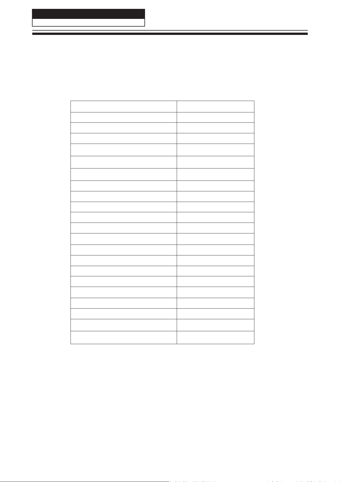
2-1. Specification list
8
Model
Screen Size 40"
Aspect Ratio 16:9
Resolution 1920x1080
Brightness (cd/m²) 280
Contrast 1500:1
Response Time (ms) 8
Angel of View H:170°, V:160°
Color Display 16.7M
OSD Language English, French ect
Color System PAL/SECAM/DVB-T/C
Audio System BG/DK/I/L
Audio Output Power (Built-in) (W) 8W×2
Audio Output Power (outer) (W) No
Total Power Input (W) 100W
Voltage Range (V) AC100V~240V
Power Frequency (Hz) 50~60Hz
Time of Sleep Timer (MINS) 240Min
Net Weight (KG) 6.85
Gross Weight (KG) 8.70
Net Dimension (MM) 883.86*548.05*248.5
Packaged Dimension (MM) 972*604*156
LE40B7000TF
Page 10
Service Manual
Model No.:
LE40B7000TF
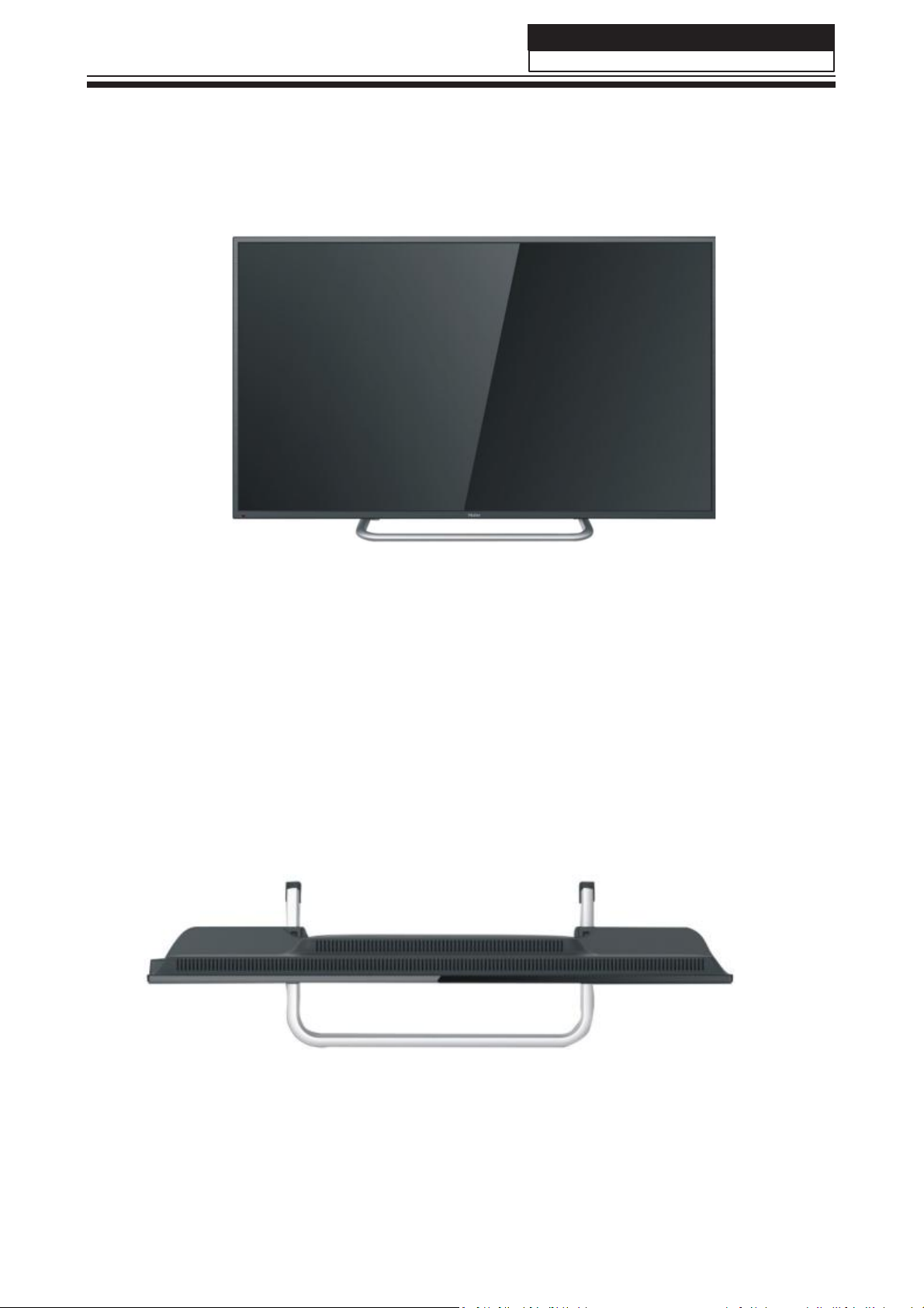
2-2. External pictures (four faces)
Front Side
Up Side
9
Page 11
Service Manual
Model No.:
LE40B7000TF
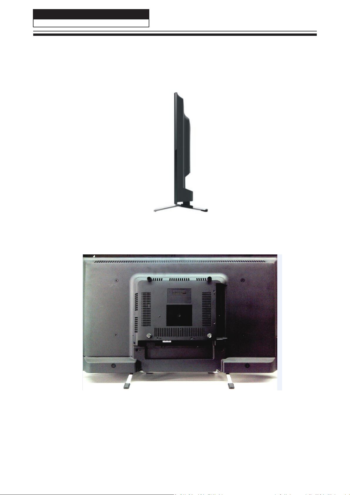
Right Side
Back Side
10
Page 12

Service Manual
Model No.:
LE40B7000TF
Chapter 3. Disassemble and Assemble
3-1.
3-1-1. Remove the Stand
3-1-2. Remove the Back Cabinet
LE40B7000TF
1. Lay down the TV set .
2. Remove the four screws from the stand which
in the picture above.
3. Remove the stand.
1.Remove the fifteen screws indicated with red
circles.
2. Flip machine, panel side up.
3.Carefully raise the Front shell from
bottom.
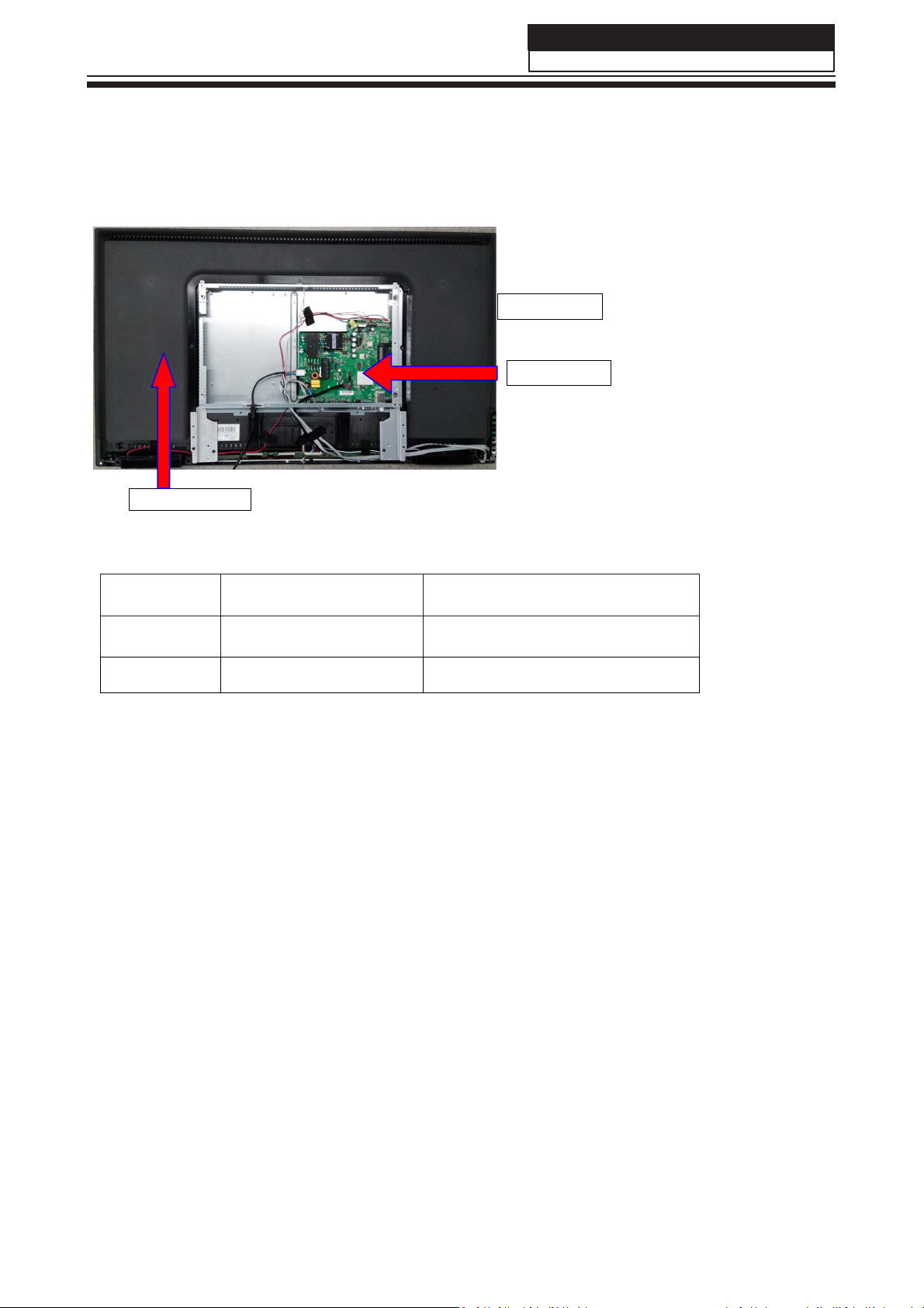
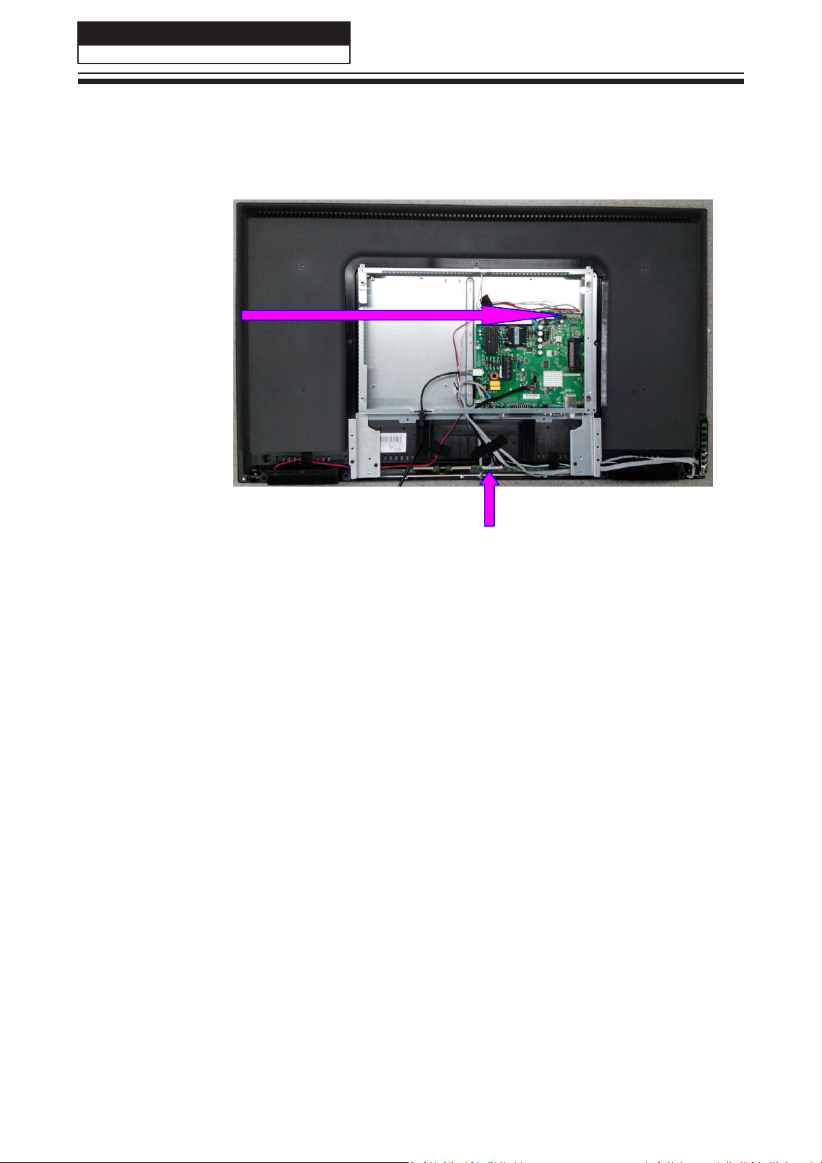
3-1-3. Remove the power-main board.
1. Remove the six screws indicated with red circles.
2. Then remove the side metal board and down metal board.
3. Remove the four screws indicated with red circles.
4. Remove the power-main board.
3-1-4. Remove the Speaker
Remove the speaker directly
11
Page 13
Service Manual
Model No.:
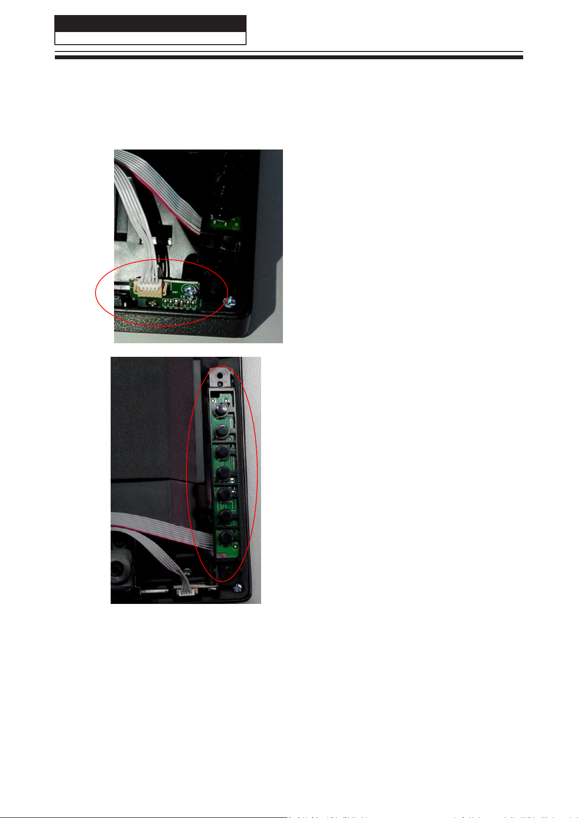
3-1-6. Remove the Remote Control Board And the Key Board
Remove the Remote Control Board and the Key Board indicated byred circle in below picture.
12
LE40B7000TF
Page 14
Service Manual
Model No.:
LE40B7000TF
Chapter 4. Location of Controls and Components
4-1. Board Location
13
B Panel
No. Parts number Description
A Board power-main board
B Panel LCD Panel
DH1U71D0M04M
2002CM39500630
A Board
Page 15
Service Manual
Model No.:
LE40B7000TF
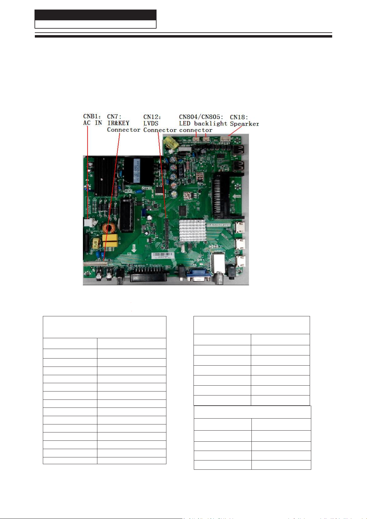
4-2. Mainboard
4-2-1. Function Description
Process signal which incept from exterior equipment then translate into signal that panel can
display.
4-2-2. Connector definition
IR & Key Interface
CN7
Pin number Signal name
1
2 K7
3 K6
4 K5
5 K4
6 K3
7 K2
8 K1
9 K0
10 GND
11 IR
12 GRE
13 RED
14 5V
14
GND
LED Backlight interface
CN804/CN805
Pin number Signal name
1
2
3
LED+
NC
LED-
Speaker connector CN18
Pin number Signal name
1
2 ROUT-
3 LOUT4 LOUT+
ROUT+
Page 16
Service Manual
Model No.:
LE40B7000TF
15
Page 17
Service Manual
Model No.:
LE40B7000TF
4-3. LCD Panel
Backlight Unit
16
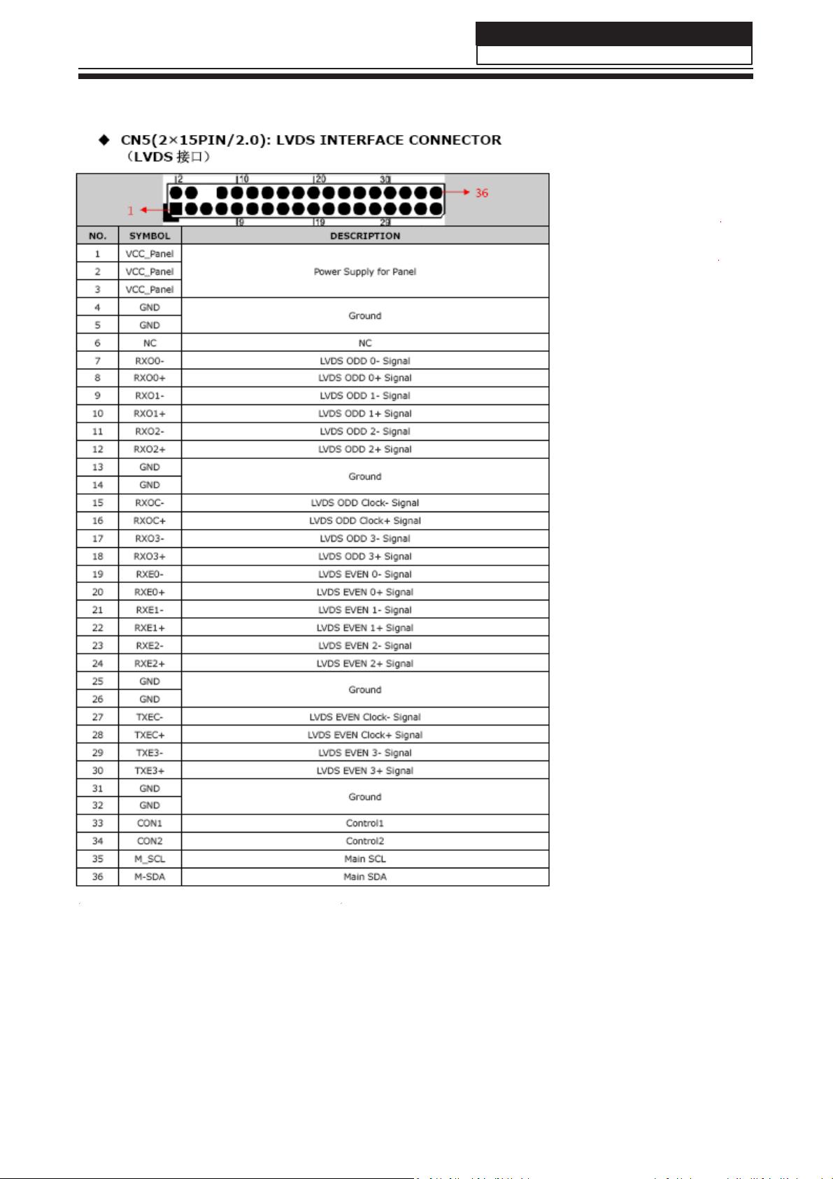
LVDS CONNECTOR CNF1
LE40B7000TF
Page 18

Service Manual
Model No.:
LE40B7000TF
17
Page 19

Chapter 5. Installation Instructions
5-1. Accessories
18
Service Manual
Model No.:
LE40B7000TF
Remote Control
Batteries
Page 20

Service Manual
Model No.:
LE40B7000TF
5-2. External Equipment Connections
Antenna Connection
Connect your aerial to the back of the TV into the
ANTENNA IN socket.
Improve Your Signal
To improve picture quality in a poor signal area, use a
signal amplifier (not supplied).
Connect Your PC to the TV
You can use your TV as a monitor for your personal
computer by connecting it with a VGA cable (not
supplied).
Read your computer user guide and check it has a
A
VGA connector.
Turn off your TV and PC.
B
Connect a D type 15-pin VGA interface cable to the
C
VGA video interface connector on the PC. Connect
the other end of the cable to the PC interface
connector on the TV. Tighten the screws on the
VGA connectors and connect the audio cable (not
supplied) to the audio input socket on the back of the
TV.
Turn on the TV firstly and then the PC.
D
Press the Source button on the TV or TV remote
E
control to set the video input mode to PC.
Once the image shows, if there is noise present,
F
change the PC mode to other resolutions, change the
refresh rate to other rate or adjust the brightness and
contrast on the menu until the picture is clear.
Connect a DVD Player to Your TV
Connect the DVD video outputs (Y, Pb, Pr) to the
COMPONENT (Y, Pb, Pr) IN socket on your TV.
Turn on the DVD player and insert a DVD disk.
A
Press the SOURCE button to select COMPONENT
B
mode.
Refer to the DVD player user guide for operating
C
instructions.
Connect a DVD Player or VCR to
Your TV
There are two ways in which you can connect a DVD
player or VCR to your TV. Make sure that both the TV
and DVD player or VCR are switched off before you
connect them.
HDMI Input
A
Connect the cable from the HDMI device to the TV
HDMI socket.
Press the SOURCE button to select HDMI mode.
B
Refer to the HDMI device user guide for how to
C
operate.
19
Page 21

Service Manual
Model No.:
LE40B7000TF
Chapter 6. Operation Instructions
6-1. Front Panel Controls
20
POWER
CH-
CH+
VOL-
Press to turn the TV on and off.
TV channel down.
TV channel up.
Press to decrease
the volume.
VOL+
MENU
SOURCE
Press to increase
Press to select the main menu.
Press to select the input source.
the volume.
Page 22

Service Manual
Model No.:
LE40B7000TF
6-2. Back Panel Controls
1 2 3 4 5 6 7 8
9 10 11 12 13 14
1 Mini AV
2 Mini YPbPr
3 Coaxial
4 SCART
5 PC Audio
6 VGA input
7 RF
8 Earphone
9 HDMI1
10 HDMI2(ARC)
11 HDMI3
12 USB1 IN
13 USB2 IN
intput
intput
input
input
input
input
output
input
input
input
input
input
21
Page 23

22
Service Manual
Model No.:
LE40B7000TF
6-3. Setting Up Your Remote Control
When using the remote control, aim it towards the remote sensor on the TV.
Page 24

1
NC
NC
NC
NC
NC
T3.15AH 250VAC
COCNB1
CNB1
!
PICNB101
PIFB101 PIFB102
L
COFB1
FB1
!
PICNB102
PICNB103
COMOVB1
MOVB1
CONTCB1
NTCB1
PINTCB101PINTCB102
!
POVCC0PANEL
POPWM0DIM
POLED0SHORT
PIMOVB101
NC
PIMOVB102
VCC_Panel
PWM-DIM
LED_SHORT
POPWM0REF
PWM-REF PWM-REF
!
A A
B B
C C
D D
FG
N
COLCB1
32
14
32
14
LCB1
PI01
PI03
PILCB101
PILCB103
COCXB1
CXB1
PI02
PI04
PILCB102
PILCB104
!
VCC_Panel
PWM-DIM
LED_SHORT
! !
PICXB102
PICXB101
CORB1
RB1 RB2
COCXB2
PICXB202
CXB2
PICXB201
CORB3
RB3 RB4
2
! ! !
PIRB102
PIRB202
CORB2
COCYB1
CYB1
PIRB101
PIRB201
PIRB302
PIRB402
COCYB2
CYB2
CORB4
PIRB301
PIRB401
! !
PICYB102
PICYB101
PICYB202
PICYB201
GND
!
32
14
!
PILCB201
PILCB203
PILCB202
PILCB204
COLCB2
LCB2
SGND
!
PIDB101 PIDB102
CODB1
DB1 DB2
CODB3
DB3 DB4
PIDB301 PIDB302
!
L
!
PIDB201 PIDB202
CODB2
CODB4
PIDB401 PIDB402
!
N
Vbridge
VCC_Panel
3
COCB111
CB111 CB112
VBL
DB808
CODB808
PIDB80801
PIDB80803
DVCC
PIRB81701
PIDB80802
RB816
CORB816
PIRB81702
PIRB81601
PIRB81602
12V
EB804
COEB804
PIEB80401
PIEB80402
GND
RB817
CORB817
PIUB80101
1
PIN1
GATE1
PICB80102
PIUB80102
2
PICB80101
COCB801
CB801
PIUB80103
3
PIN4 PIN5
4 5
PIUB80104 PIUB80105
RB806
CORB806
PIRB80601 PIRB80602
PICB80301
COCB803
CB803
PICB80302
COUB801
UB801
PIN8
8
7
6
COCB804
CB804
PIUB80108
PIUB80107
PIUB80106
L
PIRB14102
CORB141
RB141
PIRB14101
PIRB14202
CORB142
RB142
PIRB14201
PIRB14301
CORB143
RB143
BRO
PIRB14302
COCB112
PICB11101
PICB11201
PICB11102
PICB11202
SGND
PICB80701
CB807
COCB807
PICB80702
GND
PIN7
CORB802
RB802
PIN6
COCB812
CB812
PICB80401
PICB81201
PICB80402
PICB81202
GND
4
SGND
5
PILB80305
3 2
1 2
PILB80201 PILB80202
CORB801
RB801
PIRB80101PIRB80102
OVP1
PIRB80201PIRB80202
CB806
COCB806
PICB80601
PICB80602
RB805
CORB805
GND
PIRB80402
PIRB80501
RB804
CORB804
PIRB80401
COCB805
CB805
PICB80501
PICB80502
COHS1
HS1
!
COCB103
PIPCB10104
CB103
PIPCB10103
3 4
COPCB101B
PCB101B
COLB803
LB803
PILB80302PILB80303
COLB801
LB801
PILB80101PILB80102
COLB802
LB802
PWM-DIM
GATE1
PIRB80301
CORB803
RB803
PIRB80302
LED-FB
PIRB80502
HS
PIHS102
SGND
1
PIUB10101
2
PIUB10102
BRO
PIUB10103 PIUB10104
PICB10302
PIRB10402
CORB104
PICB10301
RB104
PIRB10401
CORB807
RB807
PIRB80701
PIRB82002
RB820
CORB820
PIRB82001
PIQB8090B
QB809
COQB809
Vbridge
HS
COHS2
HS2
CORB101
RB101
PIHS202PIHS203
CORB102
RB102
CORB103
RB103
COUB101
UB101
1
6
2
5
334
COCB101
CB101 CB102
COHS3
HS3
PIHS301 PIHS302
COQB801
QB801
CORB808
RB808
G
PIQB8010G
PIRB80702
PIRB80802
PIQB8090E
PIRB80801
CORB860
RB860
PIQB8090C
PIRB86001 PIRB86002
PIRB80902
RB809
CORB809
RB852
CORB852
PIRB80901
L
PIRB10102
PIRB10101
PIRB10202
PIRB10201
PIRB10302
PIRB10301
6
PIUB10106
5
PIUB10105
VCC
4
PIRB10501
PICB10102
COCB102
PICB10202
PICB10201
PICB10101
SGND
COBB802
BB802
COHS6
HS6
HS
PIHS601 PIHS602
PICB80902
DS
PIQB8010D
PICB80901
PIRB81002
PIQB8010S
PIRB81001
PIRB85202
PIRB85201
GND
PIEB101
COEB1
EB1
PIEB102
SGND
CORB106
RB106
PIRB10601
CORB107
RB107
PIRB10701 PIRB10702
CORB105
RB105
PIRB10502
PIDB10503
PIEB10701
PIEB10702
COEB107
EB107
CORB812
RB812
PIRB81201PIRB81202
RB813
CORB813
PIRB81301PIRB81302
CODB801
DB801
PIBB80201PIBB80202
PIDB80101 PIDB80102
HS
CB809
COCB809
PIRB81102
CORB810
RB810
CORB811
RB811
PIRB81101
5
PICB11402
COCB114
CB114
PICB11401
PIRB11702
CORB117
RB117
CORB118
RB118
CORB147
RB147
PIRB11701
CODB107
DB107
COBB102
BB102
PIRB10602
COQB102
QB102
PIQB1020E
CORB109
RB109
PIQB1020B
CORB108
RB108
PIQB1020C
PIRB10801
PIDB10502
3
PIZB10103
PIDB10501
3
112
CODB105
DB105
PIZB10101
PICB81002
COCB810
CB810
PICB81001
PIRB81402
RB814
CORB814
EB801
COEB801
PIRB81401
EB802
COEB802
PIRB81502
COEB803
EB803
RB815
CORB815
PIRB81501
OVP1
LED_SHORT
PIQB8020C
PIQB8020E
GND
PIRB11902
PIRB12102
PIRB14702
CORB119
RB119
CORB121
RB121
PIRB11802
PIRB11901
PIRB12101
CORB120
RB120
PIRB12002
PIRB12202
PIRB14701
CORB122
RB122
PIRB11801
PIRB12001
PIRB12201
PIDB10602
PIDB10702
CODB106
DB106
COBB101
BB101
PIDB10601
PIDB10701
COQB101
QB101
PIRB10902
PIRB10901
PIRB10802
CORB111
RB111
CORB148
RB148
CORB110
RB110
COZB101
ZB101
2
PIZB10102
PIEB80101
PIEB80102
GND
QB802
COQB802
PIBB10101
PIBB10102
DS
PIQB1010D
COCB116
CB116
PICB11602
PICB11601
G
PIQB1010G
PIQB1010S
CORB112
RB112
PIBB10201
PIRB11202
PIRB11302
CORB113
RB113
PIBB10202
PIRB11201
PIRB11301
PIRB11102
PIRB14802
CODB104
DB104
PIRB11101
PIRB14801
VCC1
SGND
PIRB11001PIRB11002
VCC1
SGND
COBB801
BB801
PIBB80101PIBB80102
LED+
PIEB80201
PIEB80301
PIEB80202
PIEB80302
CORB823
RB823 RB824
PIRB82301 PIRB82302
DVCC
DB806
CODB806
PIDB80603
PIRB85002
PIRB85001
PIDB80703
CORB850
RB850
PIQB8020B
PIRB85102
CB808
PICB80801
COCB808
CORB851
RB851
DB807
CODB807
PICB80802
PIRB85101
6
CORB127
RB127
CORB123
RB123
PIRB12301
COCB118
CORB124
RB124
CB118
PIRB12401
CORB126
RB126
PICB11801PICB11802
PIRB12701
PIRB12601
!
PIDB10201 PIDB10202
COTB101
TB101
4
10
PITB10104
PITB101010
PIDB10301 PIDB10302
CODB102
DB102
CODB103
DB103
5
9
PITB10105
PITB10109
2
6
PITB10102
PITB10106
PIDB11601
1 8
PITB10101
COCB113
CB113
CORB116
RB116
7
PITB10107
PITB10108
CYB3
PICYB302
PIDB11603
COCYB3
PICYB301
CODB116
DB116
CORB114
RB114
CORB115
RB115
PIRB11402
PIRB11502
PIRB11401
PIRB11501
PICB11302
PIDB10401
PICB11301
PIRB11602
PIDB10402
PIRB11601
PIEB10601
COEB106
EB106
PIEB10602
!
LED1 LED2 LED3 LED4
RB843 RB844
CORB824
PIRB82401 PIRB82402
LED-FB
PIDB80602
PIDB80601
PIDB80702
PIDB80701
CORB843
PIRB84301
PIQB8050C
PIQB8050B
PIQB8060B
COQB805
QB805
PIQB8050E
PIRB82502
PIRB82602
CORB825
CORB826
RB825
RB826
PIRB82501
PIRB82601
PIRB83702
PIRB83802
PIDB8040A
CODB804
CORB837
CORB838
RB838
RB837
DB804
PIDB8040K
PIRB83701
PIRB83801
GND
LED1
LED2
LED3
LED4
PIRB82702
PIRB82701
CORB839
RB839
PIRB12302
PIRB14401 PIRB14402
PIRB12402
PIRB14501 PIRB14502
PIRB12702
PIRB14601 PIRB14602
PIRB12602
PIRB14901 PIRB14902
COEB105
EB105
PIEB10401
PIEB10501
COEB104
EB104
PIEB10402
PIEB10502
PIRB12801 PIRB12802
CORB128
RB128
PIRB12901 PIRB12902
CORB129
RB129
PIRB13001 PIRB13002
CORB130
RB130
PICB11701
COCB117
CB117
PICB11702
COEB101
EB101 EB102
PIDB11602
PIEB10101
PIEB10102
GNDSGND
RB846
CORB846
PIRB84302
PIRB84601
PIRB84602
PIQB8060C
PIQB8070B
COQB806
QB806
PIQB8060E
PIRB82802
PIRB82902
CORB827
CORB828
CORB829
RB827
RB828
RB829
PIRB82801
PIRB82901
PIRB83902
PIRB84002
PIRB84102
PIRB84202
CORB840
CORB841
CORB842
RB840
RB841
RB842
PIRB83901
PIRB84001
PIRB84101
PIRB84201
CORB144
RB144
CORB145
RB145
CORB146
RB146
CORB149
RB149
COEB103
EB103
VBL
PIRB14002
PIEB10301
CORB140
RB140
PIEB10302
PIRB14001
GND
COEB102
12V
PIEB10201
PIEB10202
GND
COPCB101A
PCB101A
CORB844
PIRB84401
PIRB84402
PIQB8070C
PIQB8080C
PIQB8080B
COQB807
COQB808
QB807
PIQB8070E
PIQB8080E
PIRB83002
PIRB83102
PIRB83202
CORB830
CORB831
CORB832
RB830
RB831
PIRB83001
PIRB83101
PIRB83201
!
QB808
RB832
7
12V
PIRB13102
CORB131
RB131
PIRB13101
12
PIPCB10101
PIRB13202
CORB135
RB135
CORB132
RB132
COCB109
CB109
PIPCB10102
CORB133
RB133
PIRB13201
PICB10901
PICB10902
PIRB13301
PIRB13302
COCB110
CB110
PICB11001 PICB11002
COUB102
K
UB102
PIUB1020K
R
PIUB1020R
1
3
2
PIRB13702
PIUB1020A
CORB137
A
PIRB13701
GND
RB845
CORB845
LED-FB
PIRB84501PIRB84502
CNB804
COCNB804
12345
PICNB80401
PICNB80402 PICNB80403 PICNB80404 PICNB80405
LED1 LED2
LED+
CNB806
COCNB806
123456789
PICNB80601
PICNB80602 PICNB80603 PICNB80604 PICNB80605 PICNB80606 PICNB80607 PICNB80608 PICNB80609
LED1
LED2
LED3
LED4
COHS5
HS5
HS
PIHS501
PIHS502
12V
12V
PIRB13502
PIRB13501
PIRB13402
CORB134
RB134RB137
PIRB13401
GATE1
GND
PIN4 PIN5
RB856
CORB856
PIRB85601PIRB85602
PWM-REF
CNB802
CNB801
COCNB801
COCNB802
1
1
2
PICNB80101 PICNB80102
PICNB80201 PICNB80202
CORB847
RB847
PIRB84701PIRB84702
PIRB84801PIRB84802
RB848
CORB848
LED1 LED3
PICNB806010
10
LED+
COHS4
HS4
HS
PIHS401
PIHS402
COCNB3
CNB3
PICNB301
1
12V
PICNB302
12V
2
PICNB303
3
PICNB304
4
GND
COUB802
UB802
PIUB80201
PIUB802010
1
10
PIN8PIN1
PIUB80202
PIUB80209
2
9
PIN7
PIUB80203
PIUB80208
3
8
PIN6
PIUB80204
PIUB80207
4
7
PIUB80205 PIUB80206
5 6
PICB81101
NC
PICB81102
GND
CNB803
COCNB803
2
123
PICNB80301 PICNB80302
LED+
LED-FB
LED+
COCNB805
CNB805
12345
PICNB80501
PICNB80502 PICNB80503 PICNB80504 PICNB80505
LED3 LED4
LED+
CNB807
COCNB807
1234567
PICNB80701 PICNB80702 PICNB80703 PICNB80704 PICNB80705
LED-FBLED+
8
COCB811
CB811
PICNB80303
PICNB80706
PICNB80707
Model Name:
TP.SIS231.PT71 B13453
DRAWN:
CHK'D:
CO
1
2
3
4
5
6
7
APP'D:
DATE: REVISON:
2013-11-27 V1.0
DATE:
DATE: Electronics Group
8
Page 25

1
A A
B B
2
Power Tree
12V
Max:3600mA
3
UD1
DCDC
5V Max:2380mA
12V Max:1380mA
5V_STB
QM32
WPM2341
4
M_5V
M_5V
5
1200mA
UD41
1V0_M
DCDC
UL1
50mA
3V3_STB
LDO
460mA
UL11
3V3_M
LDO
230mA
UL61
LDO
1V5_DDR
USBA_5V
500mA
260mA
UT1
3V3_Tun
LDO
395mA
UT5
3V3_Demo
LDO
1000mA
QM2
PVCC
60mA
UA7
1.8V_AMP
LDO
3V3_M
20mA
DDR3
USB
TUNER
Demo
PANEL
AMP-174
SIS23X
6
>4.75V@500mA
7
8
1500mA
C C
D D
1
2
3
4
5
AMP-3110
6
7
8
Page 26

1
2
3
4
5
6
7
8
COCD3
CD3
A A
COED30
ED30
COCD18
PICD1801
CD18
PICD1802
12V
PIED3001
+
COCD1
COCD10
PICD101
PICD1001
CD1
CD10
PICD102
PICD1002
PIUD102 PIUD103
CORD1
RD1
PIRD101 PIRD102
PIUD107
2
7
PIED3002
470uF-16V-±20%-8×12-105 -SZ
NC/10uF-1206-X5R-±10%-16V
10uF-0805-X5R-±20%-16 V
0.1uF-0402-X7R-±10%-16V
100Kohm-0402-±5 %-1/16W
RT7257GHZSP
220pF-0402-X7R-±10%-50V
3300pF-0402-X7R-±10%-50V
22Kohm-0402-±5%-1/16W
B B
5V_STB
PIRM3201
LMBT3904LT1G
10Kohm-0402-±5%-1/16W
NC/10Kohm-0402-±5%-1/16W
CORM31
RM31
5V_EN
PIRM3101
PIRM3102
PIRM701
CORM7
RM7
PIQM310B
PIRM3202
PIQM310C
PIQM310E
PIRM702
C C
PICD301 PICD302
PIUD101
PIUD108
8
1
COUD1
UD1
BS
NC
IN
SW
EN
4
PIUD104
PIUD105
FB
GND
COMP
6
PIUD106
COCD6
CD6
PICD601
PICD602
COCD7
CD7
PICD701
PIRD401
CORD4
RD4
PICD702
PIRD402
QM32
COQM32
RM324K7ohm-0402-±5%-1/16W
CORM32
CORM33
RM33
COQM31
QM31
PIQM320S
PIQM320G
PIRM3301PIRM3302
100Kohm-0402-±5 %-1/16W
WPM2341A-3/TR
0.1uF-0402-X7R-±10%-16V
0.1uF-0402-X7R-±10%-16V
3
5
18Kohm-0402-±1%-1/16W
3K3ohm-0402-±1%-1/16W
NC/470uF-16V-±20%-8×12-105 -XL
100uF-16V-±20%-5×11-105 - - -F=2.5-XF
PIQM320D
CM32
COCM32
0.1uF-0402-X7R-±10%-16V
SMD5845-4R7M-032
COLD1
LD1
PILD101 PILD102
CORD2
RD2
PIRD301
CORD3
RD3
PIRD302
5V_M
CM33
COCM33
PICM3201
PICM3301
PICM3202
PICM3302
PIRD201PIRD202
COCD29
CD29
TEST
CO5V
5V_STB
5V
PI5V01
PIED301
+
+
COCD5
COCD28
COED3
PICD2901
PICD2902
PICD2801
CD28
ED3
PIED302
PICD2802
0.1uF-0402-X7R-±10%-16V
10uF-0805-X5R-±10%-1 0V
10uF-0805-X5R-±10%-10 V
5V_STB 3V3_STB
PICL101
PICL102
COCD20
PICD501
PICD2001
CD5
CD20
PICD502
PICD2002
UL1
COUL1
PIUL103
VI3VO
COCL1
COCL2
CL2
CL1
PICL201
PICL202
NC/10uF-0805-X5R-±10%-10V
0.1uF-0402-X7R-±10 %-16V
LC1117CLTR33
PIUL102
PIUL104
VO
ADJ
1
PIUL101
COCD2
COCD8
PICD201
PICD801
CD2
12V
POW_EN
RT7237CHGSP
10uF-0805-X5R-±20%-1 6V
10uF-0805-X5R-±20%-1 6V
0.1uF-0402-X7R-±10%-16V
100ohm-0402-±5%-1/16W
0.1uF-0402-X7R-±10%-16V
220pF-0402-X7R-±10%-50V
3300pF-0402-X7R-±10%-50V
22Kohm-0402-±5%-1/16W
2
4
CD8
PICD202
PICD802
CORD41
RD41
COCL3
COCL4
CL3
CL4
PICL401
PICL402
10uF-0603-X5R-±2 0%-6.3V
1uF-0402-X5R-±2 0%-6.3V
COCD41
PICD4101
CD41
PICD4102
2
PIUD4102 PIUD4103
7
PIRD4101PIRD4102
PIUD4107
COCD56
PICD5601
CD56
PICD5602
PIUD4101
PIUD4108
8
1
COUD41
UD41
NC
IN
EN
GND
4
6
PIUD4104
PIUD4106
COCD47
CD47
PICD4701
PICD4702
3V3_STB
CO3V30STB
PI3V30STB01
TEST
PICL301
PICL302
COCD43
CD43
PICD4301 PICD4302
3
BS
SW
5
PIUD4105
FB
COMP
COCD46
CD46
PICD4601
PICD4602
PIRD4401
CORD44
RD44
PIRD4402
PANEL_EN
10Kohm-0402-±5%-1/16W
NC/10Kohm-0402-±5%-1/16W
100ohm-0402-±5%-1/16W
0.1uF-0402-X7R-±10%-16V
PCD0504A-2R2M-T
COLD43
LD43
PILD4301 PILD4302
CORD42
RD42
PIRD4201PIRD4202
CORD43
PIRD4301
RD43
COCD25
CD25
PIRD4302
3K3ohm-0402-±1%-1/16W
12Kohm-0402-±1%-1/16W
4K7ohm-0402-±5%-1/16W
LMBT3904LT1G
CORM1
RM1
LED_SHORT
PIRM101 PIRM102
PIRM502
PIRM501
1V0_M
PI1V00M01
COCD44
COCD45
PICD2501
PICD4401
PICD4501
CD44
CD45
PICD2502
PICD4402
PICD4502
10uF-0603-X5R-±20%-6.3V
10uF-0603-X5R-±20%-6.3V
0.1uF-0402-X7R-±10%-16V
PIQM10B
PIRM1101PIRM1102
CORM11
RM11
CORM5
RM5
PWM-DIM
PWM-REF
CO1V00M
1V0_M
TEST
PVCC VCC_Panel
PIRM201
CORM2
RM2
PIRM202
PIQM10C
COQM1
QM1
PIQM10E
BL_PWM PWM-DIM
PWM-REF/ PWM-REF
COR3
COR9
PIR301
PIR901
R3
R9
PIR302
PIR902
QM2
COQM2
PIQM20S
PIQM20G
CORM3
RM3
PIRM301PIRM302
200Kohm-0402-±5 %-1/16W
ME2325-G
10uF-0805-X5R-±20 %-16V
NC/4K7ohm-0402-±5%-1/16W
TEST
PIPWM0DIM01
COPWM0DIM
PWM-DIM
TEST
PIPWM0REF01
COPWM0REF
PWM-REF
CORG16
RG16
PIRG1601 PIRG1602
CORG6
RG6
PIRG601 PIRG602
4K7ohm-0402-±5%-1/16W
4K7ohm-0402-±5%-1/16W
510ohm-040 2-±5%-1/16W
510ohm-040 2-±5%-1/16W
PIQM20D
PIRM2001
COCM6
CORM20
RM20
CM6
PICM601
PICM602
PIRM2002
R5V
5V_STB
12V
5V_M
CL11
COCL11
PICL1101
PICL1102
D D
NC/10uF-0805-X5R-±10%-10V
1uF-0402-X5R-±2 0%-10V
1
COUL11
UL11
LC1117CLTR33
VI3VO
CL12
COCL12
PICL1201
PICL1202
2
PIUL1102PIUL1103
4
PIUL1104
VO
ADJ
1
PIUL1101
3V3_M
CO3V30M
3V3_M
PI3V30M01
CL13
CL5
COCL5
COCL13
PICL501
PICL1301
PICL502
PICL1302
0.1uF-0402-X7R-±10 %-16V
10uF-0603-X5R-±2 0%-6.3V
2
TEST
5V_M
3
CODL71
DL71
PIDL710A PIDL710K
CL71
COCL71
PICL7101
PICL7102
470ohm-040 2-±1%-1/16W
100ohm-040 2-±1%-1/16W
M7(GOOD-ARK)
NC/10uF-0603-X5R-±20%-6.3 V
0.1uF-0402-X7R-±10 %-16V
COUL61
UL61
LC1117CLTRAD
PIUL6103
CL72
COCL72
PICL7201
PICL7202
VI3VO
ADJ
1
PIUL6101
PIRL7102
CL73
COCL73
RL71
CORL71
PIRL7101
CL74
COCL74
PICL7301
PICL7302
4
PIUL6104
VO
2
PIUL6102
PIRL7202
RL72
CORL72
0.1uF-0402-X7R-±10 %-16V
PIRL7201
10uF-0603-X5R-±2 0%-6.3V
10uF-0603-X5R-±2 0%-6.3V
4
1V5_DDR
CL75
COCL75
PICL7401
PICL7501
PICL7402
PICL7502
CO1V50DDR
1V5_DDR
PI1V50DDR01
TEST
5
COR5V
PIR5V02
R12V
COR12V
PIR12V02
PVCC
PIR5V01
PVCC
PIR12V01
6
NC/0ohm-0805-±5%-1/8W
0ohm-0805-±5%-1/8W
Title
Number RevisionSize
A3
Date: 2 013-11-28 Sheet of
File: F:\TP.SIS231.PT71\..\TV#01_SYSTEM POWER.SchDocDrawn By:
7
8
Page 27

1
A A
5V_STB
PIRV1501
PIRV1701
CORV15
CORV17
RV17
RV15
PIRV1502
PIRV1702
VGA_SDA
VGA_SCL
B B
100ohm-0402-±5%-1/16W
100ohm-0402-±5%-1/16W
501070114
4K7ohm-0402-±5%-1/16W
4K7ohm-0402-±5%-1/16W
47ohm-0402-±5%-1/16W
47ohm-0402-±5%-1/16W
2
VGA_TXD
CORV16
RV16
PIRV1601 PIRV1602
HS_VGA
VS_VGA
CORV18
RV18
PIRV1801 PIRV1802
11
PIAV6011
12
PIAV6012
13
PIAV6013
14
PIAV6014
15
PIAV6015
COAV6
1716
AV6
PIAV6017
1
PIAV601
6
PIAV606
2
PIAV602
7
PIAV607
3
PIAV603
8
PIAV608
4
PIAV604
9
PIAV609
5
PIAV605
10
PIAV6010
PIAV6016
CORV11
RV11
PIRV1101
PIRV1102
CORV12
RV12
PIRV1201
PIRV1202
VGA_RXD
VGA_VS
VGA_HS
3
CORV4
RV4
PIRV401 PIRV402
PIRV101
CORV1
RV1
75ohm-0402-±5%-1/16W
PIRV102
330ohm-0402-±5%-1/16W
0.047uF-0402-X7R-±10%-16V
CORV6
RV6
PIRV601 PIRV602
PIRV201
CORV2
RV2
75ohm-0402-±5%-1/16W
PIRV202
330ohm-0402-±5%-1/16W
0.047uF-0402-X7R-±10%-16V
CORV8
RV8
PIRV801 PIRV802
PIRV301
CORV3
RV3
75ohm-0402-±5%-1/16W
PIRV302
330ohm-0402-±5%-1/16W
0.047uF-0402-X7R-±10%-16V
COAV7
AV7
PJ-325
COCV4
CV4
PICV401 PICV402
COCV6
CV6
PICV601 PICV602
COCV8
CV8
PICV801 PICV802
C
PIAV70C
R1
PIAV70R1
R
PIAV70R
L1
PIAV70L1
L
PIAV70L
VGA_RIN
VGA_GIN
VGA_BIN
4
RV19
CORV19
CORV20
RV20
VGA_TXD
VGA_RXD
CORV21
RV21
PIRV1901PIRV1902
PIRV2001PIRV2002
CORV22
RV22
PIRV2101
COCV19
CV19
PIRV2102
PICV1901 PICV1902
CV20
COCV20
PICV2001 PICV2002
PIRV2202
PIRV2201
7K5ohm-0402-±5%-1/16W
10Kohm-0402-±5%-1/16W
0.1uF-0402-X7R-±10%-16V
PC_RIN
PC_LIN
7K5ohm-0402-±5%-1/16W
10Kohm-0402-±5%-1/16W
0.1uF-0402-X7R-±10%-16V
UARTA_TX
UARTA_RX
5
COAV18
AV18
PIAV1803
R
PIAV1804
L
PIAV1805
PIAV1802
SW
PIAV1801
PJ-322A (H=7.0mm)-
COAV21
AV21
POWER
GND
USB-042M-002DP
75ohm-0402-±5%-1/16W
3
YPbPr_Pb
4
YPbPr_Y
5
2
1
5
PIAV2105
DM
DP
6
PIAV2106
75ohm-0402-±5%-1/16W
YPbPr_Pr
75ohm-0402-±5%-1/16W
GND
1
USBA_5V
PIAV2101
2
USBA_M
PIAV2102
3
USBA_P
PIAV2103
4
PIAV2104
GND
10uF-0603-X5R-±20%-6.3V
NC/100uF-16V-±20%-5×11-105 - - -F=2.5-XF
COCF1
CF1
PICF101
PICF102
+
COEF41
EF41
PIEF4101
PIEF4102
PIDF410K
PIDF410A
A K
6
YPbPr_Pb
YPbPr_Pr
YPbPr_Y
PIDF420K
CODF41
DF41
DF42
PIDF420A
A K
MSMD110
F2
COF2
PIF201 PIF202
CORF41
RF41
PIRF4101 PIRF4102
RF42
CORF42
PIRF4201 PIRF4202
CODF42
5R1ohm-0402-±5%-1/16W
5R1ohm-0402-±5%-1/16W
AIES12U020R2
AIES12U020R2
5V_M
CORI33
PIRI3301
RI33
PIRI3302
PIRI3101
PIRI3102
PIRI3201
CORI32
RI32
PIRI3202
USBA_DM
USBA_DP
CORI31
RI31
CORI38
RI38
CORI34
RI34
CORI40
RI40
CORI36
RI36
COCI38
CI38
PICI3801 PICI3802
PIRI3801 PIRI3802
220ohm-0402-±5%-1/16W
0.047uF-0402-X7R-±10%-16V
COCI34
CI34
PICI3401 PICI3402
PIRI3401 PIRI3402
220ohm-0402-±5%-1/16W
0.047uF-0402-X7R-±10%-16V
COCI40
CI40
PICI4001 PICI4002
PIRI4001 PIRI4002
COCI36
CI36
PICI3601 PICI3602
PIRI3601 PIRI3602
330ohm-0402-±5%-1/16W
0.047uF-0402-X7R-±10%-16V
220ohm-0402-±5%-1/16W
0.047uF-0402-X7R-±10%-16V
7
8
HD1_Pb
HD1_Pr
HD1_SOG
HD1_Y
C C
RI4
PIRI501PIRI502
PIRI202
RI2
CORI2
PIRI201
PIRI601PIRI602
PIRI301
RI3
CORI3
PIRI302
CORI4
CI4
COCI4
AV_IN
PICI401 PICI402
PIRI401PIRI402
CI5
AV_RIN
COCI5
PICI501 PICI502
7K5ohm-0402-±5%-1/16W
10Kohm-0402-±5%-1/16W
0.1uF-0402-X7R-±10%-16V
CI6
COCI6
AV_LIN
PICI601 PICI602
7K5ohm-0402-±5%-1/16W
10Kohm-0402-±5%-1/16W
0.1uF-0402-X7R-±10%-16V
3
120ohm-0402-±5%-1/16W
100ohm-0402-±5%-1/16W
0.1uF-0402-X7R-±10%-16V
AV1-8.4-84( )-
NC/0ohm-0402-±5%-1/16W
NC/1uF-0402-X5R-±20%-6.3V
SPDIFO CF51
RF51
CORF51
PIRF5101 PIRF5102
PICF5101 PICF5102
RF52
CORF52
PIRF5201
PIRF5202
5V_M
PIRF102
RF1
CORF1
PIRF101
PICF5401
CF54
COCF54
PICF5402
GND GND
4
SPDIF_OUT
COAX
PIAV3301
PIAV3302
PIAV3303
PIAV3304
PIAV3305
AV33
COAV33
1
2
3
4
5
NC/GQ-03-08
IR Transmitter
Vin
Vcc
GND
GND
GND
COCF51
AV27
COAV27
1
COAXSPDIF_OUT
PIAV2701
PIAV2702
2
5
5
PIAV405
COAV4
AV4
GND
POWER
DM
DP
GND
GND
USB-042M-002DP
6
PIAV406
1
USBA_5V
PIAV401
2
USBB_M
PIAV402
3
USBB_P
PIAV403
4
PIAV404
CF2
COCF2
NC/10uF-0603-X5R-±20%-10V
PICF201
PICF202
PIDF20K
PIDF30K
DF2
CODF2
PIDF20A
PIDF30A
A K
A K
6
RF2
CORF2
PIRF201 PIRF202
RF3
CORF3
PIRF301 PIRF302
DF3
5R1ohm-0402-±5%-1/16W
CODF3
5R1ohm-0402-±5%-1/16W
AIES12U020R2
AIES12U020R2
USBB_DM
USBB_DP
Title
Number RevisionSize
A2
Date: 2013-11-28 Sheet of
File: F:\TP.SIS231.PT71\..\TV#02_INPUT.SchDocDrawn By:
7
8
75ohm-0402-±5%-1/16W
220ohm-0402-±5%-1/16W
0.047uF-0402-X7R-±10%-16V
AV_IN/
PIRI102
RI1
CORI1
PIRI101
RI5
AV_R
AV11
COAV11
3
AV_L
R
PIAV1103
AV_IN/
4
PIAV1104
L
5
PIAV1105
2
AV_R
PIAV1102
SW
1
PIAV1101
PJ-322A (H=7.0mm)-
D D
1
2
CORI5
RI6
CORI6
AV_L
Page 28

1
2
3
4
5
6
7
8
A A
HOTPLUG_A/
HDMI-CEC
HDMIA_SCL
HDMIA_SDA
100ohm-0402-±5%-1/16W
1000pF-0402-X7R-±10%-50V
33ohm-0402-±5%-1/16W
33ohm-0402-±5%-1/16W
CORH7
RH7
HDMIA_5V
CORS1
CORS5
PIRS501
CORS6
PIRS601
CORS8
HDMIA_5V
PIRH302
CORH3
RH3
PIRH301
PIQH10C
PIQH10B
PIQH10E
PIRH701PIRH702
PIRH801
CORH8
RH8
PIRH802
CODH11
PIDH110A
PIDH110K
CORS4
PIRS401
PIRS402
PIRS102
PIRS101
PIRS502
PIRS201
CORS2
PIRS202
PIRS602
PIRS301
CORS3
PIRS302
CORS9
PIRS901
PIRS902
PIRS802
PIRS801
HDMIA_5V
PIRH101
PIRH102
COQH1
CORH2
QH1
RH2
PIRH201PIRH202
1Kohm-0402-±5%-1/16W
LMBT3904LT1G
10Kohm-0402-±5%-1/16W
10Kohm-0402-±5%-1/16W
HDMIA_5V_DET
CORH11
PIRH1101 PIRH1102
COCS4
PICS401 PICS402
COCS5
PICS501 PICS502
COCS6
PICS601 PICS602
CORH1
RH1
HOTPLUGA
PIAV3023
PIAV3022
PIAV3021
PIAV3020
COAV3
CORH44
PIRH4401 PIRH4402
CORH45
PIRH4501 PIRH4502
PIRS1201
CORS12
PIRS1202
PIRS1101
CORS11
PIRS1102
PIRS1301
CORS13
PIRS1302
CORS10
PIRS1001 PIRS1002
PIAV301
PIAV302
PIAV303
PIAV304
PIAV305
PIAV306
PIAV307
PIAV308
PIAV309
PIAV3010
PIAV3011
PIAV3012
PIAV3013
PIAV3014
PIAV3015
PIAV3016
PIAV3017
PIAV3018
PIAV3019
CORS16
PIRS1601 PIRS1602
CORS14
PIRS1401 PIRS1402
CORS18
PIRS1801 PIRS1802
CORS0
PIRS002
PIRS001
COCS16
PICS1601 PICS1602
COCS14
PICS1401 PICS1402
COCS18
PICS1801 PICS1802
CORS19
PIRS1901PIRS1902
CORH55
PIRH5501 PIRH5502
CORH56
PIRH5601 PIRH5602
CORH57
CORH48
PIRH5701PIRH5702
PIRH4302
CORH43
PIRH4301
PIQH410C
COQH41
PIQH410B
PIQH410E
PIRH4801PIRH4802
PIRH4701
CORH47
PIRH4702
CORH42
PIRH4201PIRH4202
CORS80
PIRS8001PIRS8002
CORS81
PIRS8101PIRS8102
PIRH4101
CORH41
PIRH4102
CORS30
PIRS3001 PIRS3002
CORS23
PIRS2302
PIRS2301
COCS80
PICS8001
COCS81
PICS8101
PICS8002
PICS8102
PIAV2023
PIAV2022
PIAV2021
PIAV2020
COAV2
CORH28
PIAV201
PIAV202
PIAV203
PIAV204
PIAV205
PIAV206
PIAV207
PIAV208
PIAV209
PIAV2010
PIAV2011
PIAV2012
PIAV2013
PIAV2014
PIAV2015
PIAV2016
PIAV2017
PIAV2018
PIAV2019
PIRH2801PIRH2802
PIRH2701
CORH27
PIRH2702
PIRC901 PIRC902
COCC9
PICC901
PICC902
PIRC101 PIRC102
PIRC1101
PIRC1201
PIRC1301
PIRC1401
CORC9
CORC1
CORC11
CORC12
CORC13
CORC14
PIRC1102
PIRC1202
PIRC1302
PIRC1402
PICC402
COCC4
PICC401
CORC2
PIRC201 PIRC202
CORC3
PIRC301 PIRC302
CORC4
PIRC401 PIRC402
CORC10
PIRC1001 PIRC1002
CORH35
PIRH3501 PIRH3502
CORH36
PIRH3601 PIRH3602
CORH37
COCC1
COCC2
PICC101
PICC201
PICC102
PICC202
PIRH3701PIRH3702
CORH24
PIRH2401
CORH25
PIRH2501
PIAV20047
PIAV20048
PIAV20049
PIAV20050
PIAV20053
PIAV20054
PIAV20055
PIAV20056
PIAV20020
PIAV20046
PIAV20019
PIAV20064
PIAV20065
PIAV20066
PIAV20037
PIAV20038
PIAV20039
PIAV20040
PIAV20041
PIAV20057
PIAV20063
PIAV20062
PIAV20058
PIAV20036
PIAV20067
PIAV2007
PIAV20042
PIAV20061
PIAV2009
PIAV20015
PIAV20044
PIAV20045
PIAV20060
PIAV20016
PIAV20017
PIAV20051
PIAV20069
PIAV20070
PIRH2402
PIRH2502
COAV20
PIRH2302
CORH23
PIRH2301
PIQH210C
COQH21
CORH22
PIQH210B
PIRH2201PIRH2202
PIQH210E
PIRH2101
CORH21
PIRH2102
PIAV20030
PIAV20031
PIAV20032
PIAV2002
PIAV2003
PIAV2004
PIAV2005
PIAV2006
PIAV20029
PIAV20028
PIAV20027
PIAV20026
PIAV20025
PIAV20024
PIAV20023
PIAV20022
PIAV20012
PIAV20011
PIAV2008
PIAV20010
PIAV20021
PIAV20013
PIAV20014
PIAV20043
PIAV20059
PIAV20018
PIAV20052
PIAV20033
PIAV2001
PIAV20034
PIAV20035
PIAV20068
PIAV20071
PIAV20072
COAV1
RX2+
GND
RX2-
23
PIAV1023
RX1+
SHELL(GND)
GND
RX1-
22
PIAV1022
RX0+
SHELL(GND)
GND
RX0-
RXC+
GND
RXC-
21
PIAV1021
SHELL(GND)
CEC
NC
SCL
20
PIAV1020
SHELL(GND)
SDA
GND
+5V
HPD
HDMIA_5V
CORH4
RH4
HDMIA_SDA/
PIRH401
PIRH402
CORH5
RH5
HDMIA_SCL/
PIRH501
PIRH502
10Kohm-0402-±5%-1/16W
B B
10Kohm-0402-±5%-1/16W
COCH61
PICH6101 PICH6102
CORH65
PIRH6501
1
PIAV101
2
PIAV102
3
PIAV103
4
PIAV104
5
PIAV105
6
PIAV106
7
PIAV107
8
PIAV108
9
PIAV109
10
PIAV1010
11
PIAV1011
12
PIAV1012
13
PIAV1013
14
PIAV1014
15
PIAV1015
16
PIAV1016
17
PIAV1017
18
PIAV1018
19
PIAV1019
CORH66
GND
GND
GND
GND
GND
HDMIA_5V
PIRH6601PIRH6602
HDMIA_RX2_DP
HDMIA_RX2_DN
HDMIA_RX1_DP
HDMIA_RX1_DN
HDMIA_RX0_DP
HDMIA_RX0_DN
HDMIA_RX_CLK_DP
HDMIA_RX_CLK_DN
CEC_A
ARC
HDMIA_SCL/
HDMIA_SDA/
HOTPLUG_A/
CORH14
RH14
PIRH1401PIRH1402
CORH15
RH15
PIRH1501 PIRH1502
CORH16
RH16
PIRH1601 PIRH1602
CORH17
RH17
PIRH1701PIRH1702
2K2ohm-0402-±5%-1/16W
4K7ohm-0402-±5%-1/16W
PIRH6502
C C
COAV8
PIAV801
PIAV802
PIAV803
PIAV804
PIAV805
PIAV806
PIAV807
PIAV808
PIAV809
PIAV8010
PIAV8011
PIAV8012
PIAV8013
PIAV8014
PIAV8015
PIAV8016
PIAV8017
PIAV8018
PIAV8019
PIAV8020
PIAV8021
COCS20
CORS20
PICS2001 PICS2002
PIRS2001 PIRS2002
D D
Title
Number RevisionSize
A2
Date: 2013-11-28 Sheet of
1
2
3
4
5
6
File: F:\TP.SIS231.PT71\..\TV#03_HDMI&SCART&PCMCI.SchDocDrawn By:
7
8
Page 29

1
2
3
4
5
6
7
8
9
10
11
12
A A
COU1B
AC22
PIU10AC22
AB12
PIU10AB12
AB15
PIU10AB15
AA15
PIU10AA15
AA19
PIU10AA19
AB19
PIU10AB19
AB11
PIU10AB11
AB17
PIU10AB17
AA11
PIU10AA11
AA17
PIU10AA17
AA10
PIU10AA10
AA16
PIU10AA16
AC10
PIU10AC10
AC16
PIU10AC16
AB20
PIU10AB20
AC13
PIU10AC13
AA22
PIU10AA22
AA13
PIU10AA13
AC20
PIU10AC20
AC14
PIU10AC14
AB21
PIU10AB21
AB14
PIU10AB14
PIU10V20
PIU10W14
PIU10V18
U1B
F19
PIU10F19
AV_Y0/C0
G23
PIU10G23
AV_Y1
H22
PIU10H22
AV_Y2
ANALOG
G20
PIU10G20
AV_Y3
VIDEO
H21
PIU10H21
AV_Y4
G22
PIU10G22
AV_REF
B6
PIU10B6
DMVINP
A6
PIU10A6
DMVINN
B7
PIU10B7
DMIFGAIN
A7
PIU10A7
DMRFGAIN
F10
PIU10F10
DM25VO
J20
PIU10J20
AV_CVBSO
K20
PIU10K20
ATV_CVBSO
L19
PIU10L19
ATV_COMP
J19
PIU10J19
ATV_RSET
L1
PIU10L1
HDMIA_RXP0
L2
PIU10L2
HDMIA_RXN0
M1
PIU10M1
HDMIA_RXP1
M2
PIU10M2
HDMIA_RXN1
N1
PIU10N1
HDMIA_RXP2
N2
PIU10N2
HDMIA_RXN2
K1
PIU10K1
HDMIA_RXCP
K2
PIU10K2
HDMIA_RXCN
R1
PIU10R1
HDMIB_RXP0
R2
PIU10R2
HDMIB_RXN0
T1
PIU10T1
HDMIB_RXP1
T2
PIU10T2
HDMIB_RXN1
U1
PIU10U1
HDMIB_RXP2
U2
PIU10U2
HDMIB_RXN2
P1
PIU10P1
HDMIB_RXCP
P2
PIU10P2
HDMIB_RXCN
J3
PIU10J3
HDMI_ARC
E5
PIU10E5
HDMI_CEC
J4
PIU10J4
HDMI_RSET
F4
PIU10F4
HDMIA_HPD
G4
PIU10G4
HDMIB_HPD
G1
No ball/HDMIC_RXP0
PIU10G1
G2
NC/HDMIC_RXN0
PIU10G2
H1
PIU10H1
NC/HDMIC_RXP1
H2
NC/HDMIC_RXN1
PIU10H2
J1
PIU10J1
NC/HDMIC_RXP2
J2
NC/HDMIC_RXN2
PIU10J2
F1
PIU10F1
NC/HDMIC_RXCP
F2
NC/HDMIC_RXCN
PIU10F2
F3
PIU10F3
NC/HDMIC_HPD
SIS231C1CI
U1D
COU1D
DDR_DQM0
DDR_DQM1
DDR3
DDR_DQS0
DDR_DQS0N
DDR_DQS1
DDR_DQS1N
DDR_DQ0
DDR_DQ1
DDR_DQ2
DDR_DQ3
DDR_DQ4
DDR_DQ5
DDR_DQ6
DDR_DQ7
DDR_DQ8
DDR_DQ9
DDR_DQ10
DDR_DQ11
DDR_DQ12
DDR_DQ13
DDR_DQ14
DDR_DQ15
V20
DDR_RSTN
W14
DDR_CMPP
V18
VSS
SIS231C1CI
IN/OUT
DM
DDR_CLK
DDR_CLKN
DDR_RASN
DDR_CASN
DDR_WEN
DDR_CKE
DDR_ODT
DDR_MA0
DDR_MA1
DDR_MA2
DDR_MA3
DDR_MA4
DDR_MA5
DDR_MA6
DDR_MA7
DDR_MA8
DDR_MA9
DDR_MA10
DDR_MA11
DDR_MA12
DDR_MA13
DDR_BA0
DDR_BA1
DDR_BA2
HIGH
SPEED
ANALOG
VIDEO
INPUT
HDMI
KEYPAD
USBHDMIC
AA23
DDR_CLK_DP
PIU10AA23
AB23
DDR_CLK_DN
PIU10AB23
W15
DDR_RAS_N
PIU10W15
Y14
DDR_CAS_N
PIU10Y14
Y15
DDR_WE_N
PIU10Y15
Y22
DDR_CKE
PIU10Y22
Y20
DDR_ODT
PIU10Y20
Y16
DDR_MA0
PIU10Y16
W23
DDR_MA1
PIU10W23
W18
DDR_MA2
PIU10W18
Y18
DDR_MA3
PIU10Y18
W21
DDR_MA4
PIU10W21
W16
DDR_MA5
PIU10W16
V23
DDR_MA6
PIU10V23
V16
DDR_MA7
PIU10V16
W19
DDR_MA8
PIU10W19
V17
DDR_MA9
PIU10V17
Y23
DDR_MA10
PIU10Y23
V21
DDR_MA11
PIU10V21
Y21
DDR_MA12
PIU10Y21
Y17
DDR_MA13
PIU10Y17
Y19
DDR_BA0
PIU10Y19
W22
DDR_BA1
PIU10W22
W20
DDR_BA2
PIU10W20
YPP_R0
YPP_R0_REF
YPP_G0
YPP_G0_REF
YPP_B0
YPP_B0_REF
YPP_R1
YPP_G1
YPP_B1
YPP_SOG1
YPP_R2
YPP_G2
YPP_B2
YPP_SOG2
VGA_HS
VGA_VS
YPP_REXT
SM_GPIO43(YPP_FBI0)
SM_GPIO44(YPP_FBI1)
HSADC12VO
AUX_KEY0
AUX_KEY1
NC/No ball
USBA_DP
USBA_DM
USBB_DP
USBB_DM
B23
VGA_RIN
PIU10B23
C21
VGA_R0_REF
PIU10C21
VGA_GIN
C23
PIU10C23
C22
VGA_G0_REF
PIU10C22
D21
VGA_BIN
PIU10D21
D20
VGA_B0_REF
PIU10D20
G21
SCART_R
PIU10G21
E23
SCART_G
PIU10E23
E19
SCART_B
PIU10E19
HD_SOG
E22
PIU10E22
F21
HD1_Pr
PIU10F21
E21
HD1_Y
PIU10E21
F20
HD1_Pb
PIU10F20
E20
HD1_SOG
PIU10E20
B18
VGA_HS
PIU10B18
A18
VGA_VS
PIU10A18
A22
YPP_REXT
PIU10A22
B19
PIU10B19
MUX_VSW1
A19
PIU10A19
F18
PIU10F18
B5
KEYA
PIU10B5
KEYB
A5
PIU10A5
H6
SCART_FS /
PIU10H6
KEY2
SCART_F B/
H5
PIU10H5
W1
USBB_DP
PIU10W1
W2
USBB_DM
PIU10W2
V1
USBA_DP
PIU10V1
V2
USBA_DM
PIU10V2
VGA_R0_REF
VGA_G0_REF
VGA_B0_REF
PIR4201
R42
COR42
PIR4202
DDR_RST_N
0.1uF-0402-X7R-±10%-16V
COCV5
CV5
PICV501PICV502
PIRV501
COCV7
CV7
PICV701PICV702
PIRV701
COCV9
CV9
PICV901PICV902
PIRV901
0.047uF-0402-X7R-±10 % -16V
47ohm-0402-±5%- 1 /16W
0.047uF-0402-X7R-±10% -16V
47ohm-0402-±5%- 1 /16W
0.047uF-0402-X7R-±10% -16V
47ohm-0402-±5%- 1 /16W
6K04ohm-0402-±1%-1/16W
1V5_DDR
G7
PIU20G7
B2
PIU20B2
D9
PIU20D9
K2
PIU20K2
K8
PIU20K8
N1
PIU20N1
N9
PIU20N9
R1
PIU20R1
R9
PIU20R9
A1
PIU20A1
A8
PIU20A8
C1
PIU20C1
C9
PIU20C9
D2
PIU20D2
E9
PIU20E9
F1
PIU20F1
H2
PIU20H2
H9
PIU20H9
J1
PIU20J1
J9
PIU20J9
L1
PIU20L1
L9
PIU20L9
M7
PIU20M7
T7
PIU20T7
B1
PIU20B1
B9
PIU20B9
D1
PIU20D1
D8
PIU20D8
E2
PIU20E2
E8
PIU20E8
F9
PIU20F9
G1
PIU20G1
G9
PIU20G9
A9
PIU20A9
B3
PIU20B3
E1
PIU20E1
G8
PIU20G8
J2
PIU20J2
J8
PIU20J8
M1
PIU20M1
M9
PIU20M9
P1
PIU20P1
P9
PIU20P9
T1
PIU20T1
T9
PIU20T9
T2
PIU20T2
GND
C36
COC36
PIC3601
PIC3602
PIRV502
PIRV702
PIRV902
VDD
VDD
VDD
VDD
VDD
VDD
VDD
VDD
VDD
VDDQ
VDDQ
VDDQ
VDDQ
VDDQ
VDDQ
VDDQ
VDDQ
VDDQ
NC
NC
NC
NC
NC
NC
VSSQ
VSSQ
VSSQ
VSSQ
VSSQ
VSSQ
VSSQ
VSSQ
VSSQ
VSS
VSS
VSS
VSS
VSS
VSS
VSS
VSS
VSS
VSS
VSS
VSS
RESET#
CORV5
RV5
CORV7
RV7
CORV9
RV9
UDQS#
LDQS#
VREFDQ
VREFCA
DQ0
DQ1
DQ2
DQ3
DQ4
DQ5
DQ6
DQ7
DQ8
DQ9
DQ10
DQ11
DQ12
DQ13
DQ14
DQ15
UDM
LDM
UDQS
LDQS
BA0
BA1
BA2
RAS#
CAS#
WE#
CS#
CKE
ODT
CK#
1uF-0402-X5R-±20%-6.3V
PIC1402
COC14
C14
PIC1401
U2
COU2
E3
DDR_DQ0
PIU20E3
F7
DDR_DQ1
PIU20F7
F2
DDR_DQ2
PIU20F2
F8
DDR_DQ3
PIU20F8
H3
DDR_DQ4
PIU20H3
H8
DDR_DQ5
PIU20H8
G2
DDR_DQ6
PIU20G2
H7
DDR_DQ7
PIU20H7
D7
DDR_DQ8
PIU20D7
C3
DDR_DQ9
PIU20C3
C8
DDR_DQ10
PIU20C8
C2
DDR_DQ11
PIU20C2
A7
DDR_DQ12
PIU20A7
A2
DDR_DQ13
PIU20A2
B8
DDR_DQ14
PIU20B8
A3
DDR_DQ15
PIU20A3
D3
DDR_DQM1
PIU20D3
E7
DDR_DQM0
PIU20E7
C7
DDR_DQS1_DP
PIU20C7
B7
DDR_DQS1_DN
PIU20B7
F3
DDR_DQS0_DP
PIU20F3
G3
DDR_DQS0_DN
PIU20G3
N3
DDR_MA0
A0
PIU20N3
P7
DDR_MA1
A1
PIU20P7
P3
DDR_MA2
A2
PIU20P3
N2
DDR_MA3
PIU20N2
A3
P8
DDR_MA4
A4
PIU20P8
P2
DDR_MA5
PIU20P2
A5
R8
DDR_MA6
A6
PIU20R8
R2
DDR_MA7
PIU20R2
A7
T8
DDR_MA8
A8
PIU20T8
R3
DDR_MA9
PIU20R3
A9
L7
DDR_MA10
A10
PIU20L7
R7
DDR_MA11
PIU20R7
A11
N7
DDR_MA12
A12
PIU20N7
T3
DDR_MA13
PIU20T3
A13
M2
DDR_BA0
PIU20M2
N8
DDR_BA1
PIU20N8
M3
DDR_BA2
PIU20M3
J3
DDR_RAS_N
PIU20J3
K3
DDR_CAS_N
PIU20K3
L3
DDR_WE_N
PIU20L3
L2
PIU20L2
K9
DDR_CKE
PIU20K9
K1
DDR_ODT
PIU20K1
R66
COR66
J7
DDR_CLK_DP
CK
PIR6601 PIR6602
PIU20J7
K7
DDR_CLK_DN
PIU20K7
L8
R67
COR67
ZQ
PIR6701 PIR6702
PIU20L8
H1
PIU20H1
M8
DDR_VREF
PIU20M8
SC_RI
SC_LI
AV_RIN
AV_LIN
PC_RIN
PC_LIN
DVD_RIN
DVD_LIN
CI_D0
CI_D1
CI_D2
CI_D3
CI_D4
CI_D5
CI_D6
CI_D7
CI_A0
CI_A1
CI_A2
CI_A3
CI_A4
CI_A5
CI_A6
CI_A7
CI_A8
CI_A9
CI_A10
CI_A11
CI_A12
CI_A13
CI_WE_N
CI_OE_N
CI_WAIT_N
CI_RESET
CI_IRQA_N
CI_CE_N
CI_IORD_N
CI_IOWR_N
PCM_CD2_N
PCM_CD1_N
AU_VBG
PIU10H4
PIU10A3
PIU10A2
PIU10B2
PIU10B1
PIU10C2
PIU10C1
PIU10D2
PIU10D1
PIU10AB3
PIU10AC3
PIU10AB4
PIU10T5
PIU10T4
PIU10T6
PIU10V4
PIU10U6
PIU10AC2
PIU10AA4
PIU10AB2
PIU10AA3
PIU10AA2
PIU10AA1
PIU10Y1
PIU10Y2
PIU10Y4
PIU10W3
PIU10W4
PIU10V5
PIU10V3
PIU10Y6
PIU10Y5
PIU10V6
PIU10AB1
PIU10Y3
PIU10U3
PIU10U5
PIU10W5
PIU10W6
PIU10AC4
PIU10U4
NT5CB64M16FP-DH
100ohm-0402-±1%-1/16W
360ohm-0402-±1%-1/16W
COU1C
U1C
H4
A3
A2
B2
B1
C2
C1
D2
D1
AB3
AC3
AB4
T5
T4
T6
V4
U6
AC2
AA4
AB2
AA3
AA2
AA1
Y1
Y2
Y4
W3
W4
V5
V3
Y6
Y5
V6
AB1
Y3
U3
U5
W5
W6
AC4
U4
SIS231C1CI
AU_VBG
LINE_IN_R1
LINE_IN_L1
LINE_IN_R2
LINE_IN_L2
LINE_IN_R3
LINE_IN_L3
LINE_IN_R4
LINE_IN_L4
CI
CI_DAT0/UM_GPIO47
CI_DAT1/UM_GPIO48
CI_DAT2/UM_GPIO49
CI_DAT3/UM_GPIO50
CI_DAT4/UM_GPIO51
CI_DAT5/UM_GPIO52
CI_DAT6/UM_GPIO53
CI_DAT7/UM_GPIO54
CI_ADDR0/UM_GPIO55
CI_ADDR1/UM_GPIO56
CI_ADDR2/UM_GPIO57
CI_ADDR3/UM_GPIO58
CI_ADDR4/UM_GPIO59
CI_ADDR5/UM_GPIO60
CI_ADDR6/UM_GPIO61
CI_ADDR7/UM_GPIO62
CI_ADDR8/UM_GPIO63
CI_ADDR9
CI_ADDR10
CI_ADDR11
CI_ADDR12
CI_ADDR13
CI_WEN
CI_OEN
CI_WAITN
CI_RESET
CI_IRQN
CI_CE1N
CI_IORDN
CI_IOWRN
CI_CD2N
CI_CD1N
0.1uF-0402-X7R-±10%-16V
0.1uF-0402-X7R-±10%-16V
0.1uF-0402-X7R-±10%-16V
0.1uF-0402-X7R-±10%-16V
0.1uF-0402-X7R-±10%-16V
0.1uF-0402-X7R-±10%-16V
0.1uF-0402-X7R-±10%-16V
0.1uF-0402-X7R-±10%-16V
0.1uF-0402-X7R-±10%-16V
AUDIO
INPUT/OUTPUT
1V5_DDR
PIR5301
PIR5302
PIR5601
PIR5602
GND
AUDIO
INPUT
SIF
SPDIF OUTPUT
AUDIO
I2S
OUTPUT
I2S_OUT_S D1_LINEOUT
TRANSPORT
STREAM
TS_DAT1/SM_GPIO36
TS_DAT2/SM_GPIO37
TS_DAT3/SM_GPIO38
TS_DAT4/SM_GPIO39
TS_DAT5/SM_GPIO40
TS_DAT6/SM_GPIO41
TS_DAT7/SM_GPIO42
CATS
R53
COR53
1Kohm-0402-±1%-1/16W
1Kohm-0402-±1%-1/16W
R56
COR56
CLOSE TO DIVIDER
C6
C9
COC6
COC9
PIC601
PIC901
PIC602
PIC902
LINE_OUT_R
LINE_OUT_L
SPDIF_OUT
I2S_OUT_C LK
I2S_MCLK
I2S_OUT_W S
I2S_OUT_S D0_SPK
I2S_OUT_S D2
I2S_OUT_S D3
TS_CLK
TS_VALID
TS_FRAME
TS_DAT0
CATS_CLK
CATS_VALID
CATS_FRAME
CATS_DAT0
CATS_DAT1
CATS_DAT2
CATS_DAT3
CATS_DAT4
CATS_DAT5
CATS_DAT6
CATS_DAT7
C8
C7
COC7
COC8
PIC701
PIC801
PIC2301
PIC702
PIC802
PIC2302
GND
HP_R
HP_L
SPK_R
SPK_L
SIF
C23
COC23
PIC2401
PIC2402
PIU10B4
PIU10C4
PIU10B3
PIU10C3
PIU10E4
PIU10D4
PIU10G19
PIU10W12
PIU10Y11
PIU10V12
PIU10W13
PIU10Y12
PIU10W11
PIU10V11
PIU10Y13
PIU10Y8
PIU10W8
PIU10V10
PIU10W10
PIU10Y10
PIU10V9
PIU10W9
PIU10Y9
PIU10V8
PIU10W7
PIU10Y7
PIU10AA7
PIU10AB6
PIU10AA6
PIU10AB5
PIU10AC5
PIU10AA5
PIU10AB8
PIU10AC8
PIU10AA8
PIU10AC7
PIU10AB7
CLOSE TODRAM
C28
C24
COC24
COC28
PIC2801
PIC2802
B4
C4
B3
C3
E4
D4
G19
W12
Y11
V12
W13
Y12
W11
V11
Y13
Y8
W8
V10
W10
Y10
V9
W9
Y9
V8
W7
Y7
AA7
AB6
AA6
AB5
AC5
AA5
AB8
AC8
AA8
AC7
AB7
C30
COC30
PIC3001
PIC3201
PIC3002
PIC3202
10uF-0603-X5R-±20%-6.3V
1uF-0402-X5R-±20%-6.3V
1uF-0402-X5R-±20%-6.3V
EARPHONE_ROUT
EARPHONE_LOUT
AMP RIN
AMP LIN
SC_ROUT /
SC_LOUT/
SPDIFO
I2S_OUT_BC K
I2S_MCLK
I2S_OUT_W S
I2S_OUT_S D
TSI_CK
TSI_VLD
TSI_START
TSI_D0
TSI_D1
TSI_D2
TSI_D3
TSI_D4
TSI_D5
TSI_D6
TSI_D7
TSO_CK
TS_MOVAL0
TS_MOST ART0
TSO_D0
TSO_D1
TSO_D2
TSO_D3
TSO_D4
TSO_D5
TSO_D6
TSO_D7
C34
C32
C33
COC32
COC33
COC34
PIC3301
PIC3401
PIC3302
PIC3402
1V5_DDR
PIC3501
PIC3502
C35
COC35
CN7
COCN7
1
PICN701
2
PICN702
3
PICN703
4
PICN704
5
PICN705
6
PICN706
7
PICN707
8
PICN708
9
PICN709
10
PICN7010
11
PICN7011
12
PICN7012
13
PICN7013
14
PICN7014
14PIN-2.0-D-H-G-B
5V_IR
LED_R
LED_G/B
IR
GND
K0/AD
K1
K2
K3
K4
K5
K6/AD
K7
GND
COU1A
U1A
XTALI
B20
PIU10B20
OSCI_24M
XTALO
A20
PIU10A20
OSCO_24M
OSC
D10
RESET_H
PIU10D10
PIU10C10
PIU10A21
GND
PIU10B21
PWM-REF/
PIU10A10
AMP_RST
PIU10C14
PANEL_EN
PIU10C15
PIU10C11
12V_EN
PIU10D11
AMP_IRQ_N
PIU10D16
AMP_MUTE
PIU10C17
PIU10D17
AMP_STB
PIU10D19
DEBUG0
PIU10B16
DEBUG1
PIU10A14
DEBUG2
PIU10A15
DEBUG3
PIU10B15
DEBUG4
PIU10B14
DEBUG5
PIU10A16
CF_WP_N
PIU10A12
PWM/ADJ_EN
PIU10B12
PH-DET
PIU10D15
DVD_EN
PIU10C19 PIU10C20
GPIO23
PIU10D13
DEMO_RST
PIU10C16
PIU10C18
LED_R/
PIU10D14
DVD_IR
PIU10D18
SPI_CS1_N
PIU10B10
PIU10C13
5V_EN
PIU10D9
UARTA_TX
PIU10D5
UARTA_RX
PIU10C5
REMOTE
PIU10D6
POW_EN
PIU10C6
PIU10E6 PIU10F5
HDMIA_5V_DET
PIU10D7
HDMIB_5V_DET
PIU10C7
HDMIC_5V_DET
PIU10B9
Tun_SCL
PIU10C8
Tun_SDA
PIU10D8
BL_EN
PIU10C9
DVD_DAT
PIU10A8
DVD_STB
PIU10B8
BL_PWM
PIU10A9
5V_STB
PIRK1502
RK15
RK16
IR
PIRK1501
4K7ohm-0402-±5%-1/16W
1Kohm-0402-±5%- 1 /16W
RK1
CORK1
PIRK101
PIRK102
RK2
CORK2
PIRK201
PIRK202
RK3
CORK3
PIRK301
PIRK302
RK4
CORK4
PIRK401
PIRK402
RK5
CORK5
PIRK501
PIRK502
RK7
CORK7
PIRK701
PIRK702
1K5ohm-0402-±5%-1/16W
4K7ohm-0402-±5%-1/16W
12Kohm-0402-±5%-1/16W
AUX_PWROK
C10
PWRBTN_N
A21
ENTEST
B21
ENDEBUG
A10
PWM1
C14
SA_GPIO1/MAIN_LED
C15
SA_GPIO2/LCDVDD_EN
C11
SA_GPIO3/EXT_LRSYNC
D11
SA_GPIO4
D16
SA_GPIO5
C17
SA_GPIO6/SPK_MUTE
D17
SA_GPIO7/SPK_EN
D19
SA_GPIO8/HP_DET
B16
SA_GPIO9
A14
SA_GPIO10
A15
SA_GPIO11
B15
SA_GPIO12
B14
SA_GPIO13
A16
SA_GPIO14
A12
SA_GPIO15/CF_WP_N
B12
SA_GPIO16/25MCK_IN
D15
SA_GPIO17
C19
SA_GPIO24
D13
SA_GPIO23/ENC_SPI_N
C16
SA_GPIO25/U_2SP I
C18
SA_GPIO26
D14
SA_GPIO27/PWM0
D18
SA_GPIO28
B10
SA_GPIO29/SPI_CS1
C13
SA_GPIO31/CK24.576O
D9
SA_GPIO34/PWM2/BL_ADJ
D5
UARTA_TX
C5
UARTA_RX
D6
IR
C6
PS_ON
E6
UA_GPIO0
D7
UA_GPIO18
C7
UA_GPIO19
B9
UA_GPIO20
C8
UA_GPIO21/AUX_SCL
D8
UA_GPIO22/AUX_SDA
C9
UA_GPIO30/BLEN_N
A8
UA_GPIO32/UARTB_ RX
B8
UA_GPIO33/UARTB_ TX
A9
UA_GPIO35/PWM3
SIS231C1CI
CORK15
CORK16
PIRK1601PIRK1602
UA/UM series
REMOTE
330ohm-0402-±5% -1/16W
5V_STB
RK34
CORK34
RK10
CORK10
PIRK1001 PIRK1002
4K7ohm-0402-±1%-1/16W
4K7ohm-0402-±1% -1/16W
RK11
CORK11
PIRK1101 PIRK1102
4K7ohm-0402-±5%-1/16W
12Kohm-0402-±5%-1/16W
1K5ohm-0402-±5%-1/16W
MISC
PIRK3401PIRK3402
3V3_STB
3V3_STB
B11
SPI_CLK
PIU10B11
SPI_CLK
A11
SPI_DO
PIU10A11
SPI_DO
B13
FLASH_SPI_DI
PIU10B13
SPI
SPI_DI
A13
SPI_CS0_N
PIU10A13
SPI_CS0N
I2C
DDC
LVDS
LVDSA_TX0P
LVDSA_TX0N
LVDSA_TX1P
LVDSA_TX1N
LVDSA_TX2P
LVDSA_TX2N
LVDSA_TX3P
LVDSA_TX3N
LVDSA_TX4P
LVDSA_TX4N
LVDSA_CLKP
LVDSA_CLKN
LVDSB_TX0P
LVDSB_TX0N
LVDSB_TX1P
LVDSB_TX1N
LVDSB_TX2P
LVDSB_TX2N
LVDSB_TX3P
LVDSB_TX3N
LVDSB_TX4P
LVDSB_TX4N
LVDSB_CLKP
LVDSB_CLKN
UM_MS_SCL
UM_MS_SDA
HDMIA_SCL
HDMIA_SDA
HDMIB_SDA
NC/HDMIC_SCL
NC/HDMIC_SDA
LRSYNC
HDMIB_SCL
VGA_SCL
VGA_SDA
LED_R/
NC/27Kohm-0402-±5%-1/16W
U21
PIU10U21
U22
PIU10U22
T21
PIU10T21
T22
PIU10T22
T23
PIU10T23
R21
PIU10R21
P21
PIU10P21
P22
PIU10P22
N21
PIU10N21
N22
PIU10N22
R23
PIU10R23
R22
PIU10R22
N23
PIU10N23
M21
PIU10M21
M23
PIU10M23
M22
PIU10M22
L21
PIU10L21
L22
PIU10L22
K23
PIU10K23
J21
PIU10J21
J23
PIU10J23
J22
PIU10J22
K21
PIU10K21
K22
PIU10K22
LRSYNC_MEMC
C20
AB9
PIU10AB9
AA9
PIU10AA9
F6
PIU10F6
F5
G6
PIU10G6
G5
PIU10G5
H3
PIU10H3
G3
PIU10G3
B17
PIU10B17
A17
PIU10A17
1Kohm-0402-±5%- 1 /16W
10Kohm-0402-±5% -1/16W
LMBT3904LT1G
3V3_STB
PIRK1402
RK14
CORK14
RK17
CORK17
PIRK1401
PIRK1701 PIRK1702
RXE4_P
RXE4_N
RXE3_P
RXE3_N
RXEC_P
RXEC_N
RXE1_P
RXE1_N
RXE0_P
RXE0_N
RXE2_P
RXE2_N
RXO4_P
RXO4_N
RXO3_P
RXO3_N
RXOC_P
RXOC_N
RXO1_P
RXO1_N
RXO0_P
RXO0_N
RXO2_P
RXO2_N
M_SCL
M_SDA
HDMIA_SCL
HDMIA_SDA
HDMIB_SCL
HDMIB_SDA
HDMIC_SCL
HDMIC_SDA
VGA_SCL
VGA_SDA
PIQK10B
5V_M
PIRK1802
RK18
CORK18
PIRK1801
LED_G/B
QK1
COQK1
PIQK10C
PIQK10E
LED_R/
KEYA
PIR57801 PIR57802
KEYB
COCN12
CN12
1 2
VCC_Panel
PICN1201 PICN1202
3 4
VCC_Panel
PICN1203 PICN1204
GND
5 6
PICN1205 PICN1206
RXO0_N
7 8
PICN1207 PICN1208
9 10
PICN1209
PICN12010
RXO2_N
11 12
PICN12011 PICN12012
13 14
GND
PICN12013 PICN12014
15 16
PICN12015 PICN12016
17 18
PICN12017 PICN12018
3V3_M
19 20
RXE0_N RXE0_P
PICN12019 PICN12020
21 22
PICN12021 PICN12022
PIRF6702
RXE2_N
23 24
PICN12023 PICN12024
CORF67
RF67
25 26
GND GND
PICN12025 PICN12026
RXEC_N RXEC_P
27 28
PICN12027 PICN12028
29 30
RXE3_N
PICN12029 PICN12030
PIRF6701
31 32
GND
PICN12031 PICN12032
CON1/
33 34
PICN12033 PICN12034
M_SCL/
35 36
PICN12035 PICN12036
RXO4_N
37 38
PICN12037 PICN12038
RXE4_N
39 40
PICN12039 PICN12040
2×20PIN-2.0-D-H-M( =2.6mm)-LK( 6PIN)
100ohm-0402-±5%-1/16W
NC/100ohm-0402-±5%-1/16W
4K7ohm-0402-±5%-1/16W
4K7ohm-0402-±5%-1/16W
100ohm-0402-±5%-1/16W
100ohm-0402-±5%-1/16W
CORF63
RF63
M_SCL/
PIRF6301PIRF6302
RF64
M_SDA/
CORF64
PIRF6401PIRF6402
CORF65
RF65
PWM-DIM
PIRF6501 PIRF6502
NC/0ohm-0402-±5% -1/16W
COR17
R17
XTALO
PIR1701 PIR1702
PIY101
Y1
COY1
PIY102
XTALI
33pF-0402-NPO-±5%-50V
33pF-0402-NPO-±5%-50V
33ohm-0402-±5%-1/16W
24.576MHz-±30PPM-20PF-HC-49S
4K7ohm-0402-±5%-1/16W
10Kohm-0402-±5%-1/16W
R1
COR1
PIR101 PIR102
R2
COR2
PIR201PIR202
3V3_STB
R8
RESET_H
COR8
PIR801 PIR802
C13
COC13
1Kohm-0402-±5%- 1 /16W
10Kohm-0402-±5% -1/16W
1uF-0402-X5R-±20%-6.3V
U5
COU5
SPI_CS0_ N
1
S#
PIU501
FLASH_SPI_ DI
2
R57 8
COR578
Q
PIU502
WP_NCF_ WP_N SPI_CLK
3
W#/VPP
PIU503
PIR1002
VSS4D
PIU504
R10
COR10
G D25Q64BSIG
PIR1001
1Ko h m -0402-±5% - 1 /16W
10Kohm-0402-±5%-1/16W
0.1uF-0402-X7R-±10 % - 1 6V
VCC_Panel
GND
RXO0_P
RXO1_PRXO1_ N
RXO2_P
GND
RXOC_PRXOC_N
RXO3_PRXO3_ N
RXE1_PR XE1_N
RXE2_P
RXE3_P
GND
Display
M_SDA/
RXO4_P
RXE4_P
3V3_M
RF61
RF62
PIRF6101
PIRF6201
CORF61
CORF62
PIRF6102
PIRF6202
C3
COC3
PIC301 PIC302
C2
COC2
PIC201 PIC202
SPI_CLK
GPIO23
PIC1301
PIC1302
VCC
HOLD#
M_SCL
M_SDA
Display
PIR701
PIR702
C
3V3_M
CORF68
RF68
R7
COR7
PIC13001 PIC13002
PIU508
PIU507
PIU506
PIU505
PIRF6802
PIRF6801
3V3 _ S T B
C130
COC130
8
7
6
SPI_DO
5
1Kohm-0402-±5%- 1 /16W
0.1uF-0402-X7R-±10% -1 6V
1uF -0402-X5R-±20%-6.3V
47ohm-0402-±5% -1 /16W
0.047uF-0402-X7R-±10 % -16V
IF_AGC
COC208
C208
PIC20802
PIC20801
PIR5201
PIR5202
0.1uF-0402-X7R-±10 % - 1 6V
9K1 o h m-0402-±1 % -1/16W
499ohm-0402-±1%-1/16W
B B
PIR5101
PIR5102
C C
PIR5802
R58
COR58
PIR5801
CORI8
RI8
PIRI801
COR576
R576
3V3_M
COR52
R52
COR51
R51
75ohm-0402-±5%-1 /16W
COCI8
CI8
PIRI802
PICI801 PICI802
PIR57601PIR57602
DDR_DQM0
DDR_DQM1
DDR_DQS0_DP
DDR_DQS0_DN
DDR_DQS1_DP
DDR_DQS1_DN
DDR_DQ0
DDR_DQ1
DDR_DQ2
DDR_DQ3
DDR_DQ4
DDR_DQ5
DDR_DQ6
DDR_DQ7
DDR_DQ8
DDR_DQ9
DDR_DQ10
DDR_DQ11
DDR_DQ12
DDR_DQ13
DDR_DQ14
DDR_DQ15
DDR_RST_N
DDR_CMPP
COC16
C16
COC17
C17
SVIDEO1_C
SVIDEO1_Y
AV_IN
SCART_VI
VCOM
IF+
IF-
PIC1601PIC1602
SCART_VOUT/
PIC1701PIC1702
ATV_RSET
HDMIA_RX0_DP
HDMIA_RX0_DN
HDMIA_RX1_DP
HDMIA_RX1_DN
HDMIA_RX2_DP
HDMIA_RX2_DN
HDMIA_RX_CLK_DP
HDMIA_RX_CLK_DN
HDMIB_RX0_DP
HDMIB_RX0_DN
HDMIB_RX1_DP
HDMIB_RX1_DN
HDMIB_RX2_DP
HDMIB_RX2_DN
HDMIB_RX_CLK_DP
HDMIB_RX_CLK_DN
HDMI_ARC
HDMI-CEC
HDMI_RSET
HOTPLUGA
HOTPLUGB
HDMIC_RX0_DP
HDMIC_RX0_DN
HDMIC_RX1_DP
HDMIC_RX1_DN
HDMIC_RX2_DP
HDMIC_RX2_DN
HDMIC_RX_CLK_DP
HDMIC_RX_CLK_DN
HOTPLUGC
D D
Title
Number RevisionSize
A1
Date: 2013-11-28 Sheet of
1
2
3
4
5
6
7
8
9
10
File: F:\TP.SIS231.PT71\..\TV#04_SIS2x1_DDR_FLASH.SchDocDrawn By:
11
12
Page 30

1
2
3
4
5
6
7
8
1V0_M
COR4
R4
COU1F
U1F
PIU10AA12 PIU10AA14 PIU10AA18 PIU10AA20 PIU10AB10 PIU10AB13 PIU10AB16 PIU10AB18 PIU10AB22 PIU10AC12 PIU10AC17 PIU10AC19
AA12
AA14
AA18
AA20
AB10
AB13
A A
B B
C C
1V5_DDR
3V3_M
3V3_M_DDR
T15
PIU10T15
T16
PIU10T16
T17
PIU10T17
E10
PIU10E10
F15
PIU10F15
PIU10H7
P10
PIU10P10
PIU10P9
R11
PIU10R11
R13
PIU10R13
R14
PIU10R14
OVDD1P5
OVDD1P5
OVDD1P5
OVDD3P3
OVDD3P3
H7
OVDD3P3
OVDD3P3
P9
OVDD3P3
OVDD3P3
OVDD3P3
OVDD3P3
PIU10K9
1V0_M
3V3_M
3V3_M
AB16
VSS
VSS
VSS
VSS
VSS
VSS
VSSK9VSS
VSS
VSS
VSS
VSS
PIU10L10 PIU10L11 PIU10L12 PIU10L13 PIU10L14 PIU10L15 PIU10M10 PIU10M11 PIU10M12 PIU10M13 PIU10M14 PIU10M15
L10
L11
L12
L13
L14
L15
AVDD1P0_HDMI
AVDD3P3_HDMI
PIU10B22
PIU10F11 PIU10F12 PIU10F13
AB18
AB22
AC12
AC17
VSS
VSS
VSS
VSS
VSS
VSSL9VSS
VSS
PIU10L9
M10
M11
M12
PIU10K7
G17
PIU10G17
G18
PIU10G18
H18
PIU10J18
E16
PIU10E16
E17
PIU10E17
PIU10J17
K17
PIU10K17
PIU10L5
PIU10L6
PIU10L3
PIU10M6
PIU10N6
PIU10G8
PIU10F8
PIU10H8
PIU10F9
PIU10G11 PIU10G12 PIU10G13 PIU10G14 PIU10G15
AC19
B22
F11
F12
F13
G11
G12
G13
VSS
VSS
VSS
VSS
VSS
VSS
VSS
VSS
VSS
VSS
VSS
VSS
VSS
VSSN3VSST3VSS
VSS
VSS
PIU10N3
PIU10T3
V14
V19
M13
M14
K7
J18
J17
L5
L6
L3
M6
N6
G8
F8
H8
F9
V22
M15
U1E
COU1E
AVDD1P0_HDMI
AVDD1P0_HSADC
AVDD1P0_HSADC
AVDD1P0_HSADC
AVDD3P3_ATV
AVDD3P3_HSADCAFE
AVDD3P3_HSADCAFE
AVDD3P3_LVDS
AVDD3P3_LVDS
AVDD3P3_HDMI
AVDD3P3_HDMI
AVDD3P3_HDMIC
AVDD3P3_USB
AVDD3P3_USB
AVDD3P3_AUHP
AVDD3P3_AUHP
AVDD3P3_AU
AVDD3P3_DM
PIU10H11 PIU10H12 PIU10H13 PIU10H14 PIU10H15
G14
G15
H11
H12
H13
H14
H15
VSS
VSS
VSS
VSS
VSS
VSS
VSS
VSS
VSS
PIU10F14
F14
W17
PIU10J9
PIU10J10 PIU10J11 PIU10J12 PIU10J13 PIU10J14 PIU10J15
J10
J11
VSS
NC/No bal l
U15
U16
PIU10K10 PIU10K11 PIU10K12 PIU10K13 PIU10K14 PIU10K15
J12
J13
J14
J15
K10
K11
K12
VSS
VSS
VSS
VSS
VSS
VSSJ9VSS
VSS
VSS
NC/No bal l
NC/No bal l
NC/No bal l
NC/No bal l
NC/No bal l
NC/No bal l
PIU10T19 PIU10T20PIU10U15 PIU10U16 PIU10U17 PIU10U19 PIU10U20PIU10V14 PIU10V19 PIU10V22 PIU10W17
T19
T20
U17
U19
U20
1V5_DDR
AVSS3P3_DM
AVSS3P3_ATV
AVSS3P3_HDMIC
AVSS3P3_AUHP
AVSS3P3_AUHP
AVSS3P3_AU
AVSS3P3_USB
AVSS3P3_USB
K13
K14
K15
VSS
VSS
OVDD3P3_AUX
OVDD3P3_AUX
G10
PIU10G10
J16
PIU10J16
J8
PIU10J8
G9
PIU10G9
H10
PIU10H10PIU10H18
H9
PIU10H9
M8
PIU10M8
M9
PIU10M9
SIS231C1CI
PIU10K3
K3
VSS
VSS
IVDD1P0
IVDD1P0
IVDD1P0
IVDD1P0
IVDD1P0
IVDD1P0
IVDD1P0
IVDD1P0
IVDD1P0
IVDD1P0
IVDD1P0
IVDD1P0
IVDD1P0
IVDD1P0
F16
PIU10F16
K18
PIU10K18
K8
PIU10K8
L8
PIU10L8
M18
PIU10M18
N10
PIU10N10
N11
PIU10N11
N12
PIU10N12
N13
PIU10N13
N14
PIU10N14
N15
PIU10N15
N16
PIU10N16
N8
PIU10N8
N9
PIU10N9
C12
PIU10C12
D12
PIU10D12
1V0_M
3V3_STB
0ohm-0402-±5%-1/16W
1uF-0402-X5R-±20%-6.3V
0ohm-0402-±5%-1/16W
1uF-0402-X5R-±20%-6.3V
1uF-0402-X5R-±20%-6.3V
1uF-0402-X5R-±20%-6.3V
PIR401 PIR402
3V3_M
COR6
R6
PIR601 PIR602
3V3_M_DDR 3V3_M
COC5
PIC501
C5
PIC502
3V3_STB
C55
C18
COC18
COC55
PIC1801
PIC5501
PIC1802
PIC5502
1000pF-0402-X7R-±10%-50V
10uF-0603-X5R-±20%-6.3V
AVDD1P0_HDMI
COC45
C45
PIC4501
PIC4502
3V3_M_DDR
COC64
C64
PIC6401
PIC6402
COC11
PIC1101
C11
PIC1102
C59
COC59
1uF-0402-X5R-±20%-6.3V
10uF-0603-X5R-±20%-6.3V
1V0_M
C60
COC60
PIC5901
PIC5902
PIC6001
PIC6002
3V3_M
COR5
R5
PIR501
0ohm-0402-±5%-1/16W
1uF-0402-X5R-±20%-6.3V
1V5_DDR
COC10
PIC1001
C10
PIC1002
1uF-0402-X5R-±20%-6.3V
1uF-0402-X5R-±20%-6.3V
1V5_DDR
C70
C73
COC70
COC73
PIC7001
PIC7002
1uF-0402-X5R-±20%-6.3V
0.1uF-0402-X7R-±10%-16V
PIR502
C384
PIC38401
PIC38402
PIC7301
PIC7302
COC384
1V0_M
0.1uF-0402-X7R-±10%-16V
0.1uF-0402-X7R-±10%-16V
10uF-0603-X5R-±20%-6.3V
AVDD3P3_HDMI
COC15
PIC1501
C15
PIC1502
3V3_M
C66
C67
COC66
COC67
PIC6601
PIC6602
C386
COC386
PIC6701
PIC38601
PIC6702
PIC38602
D D
Title
SIS231C1CI
1
2
3
4
5
6
Number RevisionSize
A3
Date: 2 013-11-28 Sheet of
File: F:\TP.SIS231.PT71\..\TV#05_SIS2x1_Power.SchDocDrawn By:
7
8
Page 31

1
A A
AMPVCC
COCA23
CA23
CORA1
RA1
AMPVCCAVCC
PIRA101PIRA102
10ohm-0603-±5%-1/10W
100ohm-0402-±5 % -1/16W
0.033uF-0402-X7R-±10%-16V
B B
0.1uF-0402-X7R-±10%-16V
0.1uF-0402-X7R-±10%-16V
NC/100Kohm-0402-±5 %-1/16W
0ohm-0402-±5 % -1/16W
CORA21
AMP LIN
C C
AMP RIN
100ohm-0402-±5 % -1/16W
0.033uF-0402-X7R-±10%-16V
0.1uF-0402-X7R-±10%-16V
0.1uF-0402-X7R-±10%-16V
RA21
GND
CORA10
RA10
PIRA2101PIRA2102
PIRA1001PIRA1002
COCA27
CA27
PICA2702
PICA2701
COCA29
CA29
PICA2901
AVCC
PICA2902
0.1uF-0402-X7R-±10%-16V
1uF-0603-X5R-±10%-25V
12Kohm-0402-±5 % -1/16W
1uF-0603-X5R-±10%-25V
NC/10Kohm-0402-±5%-1/16W
TPA3110LD2PWPR
COCA15
CA15
PICA1501 PICA1502
PICA1801 PICA1802
COCA18
CA18
PIEA301
+
COEA3
PICA2301
EA3
PIEA302
PICA2302
AMP_MUTE/
COCA6
CA6
PICA601 PICA602
COCA8
CA8
CORA8
RA8
CORA2
RA2
PIRA801PIRA802
PIRA201PIRA202
COCA28
CA28
PICA2801PICA2802
CORA11
RA11
PIRA1101PIRA1102
CORA12
RA12
PIRA1201PIRA1202
COCA21
CA21
PICA2101PICA2102
PICA801PICA802
AVCC
CODA1
DA1
NC/SK34A-SMA
470uF-16V-±20%-8×12-105 -XL
0.1uF-0603-X7R-±10%-50V
COUA1
UA1
1
PIUA101
SD
2
PIUA102
FAULT
3
PIUA103
LINP
4
PIUA104
LINN
5
PIUA105
GAIN0
6
PIUA106
GAIN1
7
PIUA107
AVCC
8
PIUA108
AGND
9
PIUA109
GVDD
10
PIUA1010
PLIMIT
COCA20
11
CA20
PICA2001PICA2002
PIUA1011
RINN
12
PIUA1012
RINP
13
PIUA1013
NC
14
PIUA1014
PBTL
2
12V
COCA10
PIDA10APIDA10K
AMPVCC
COCA2
COCA3
CA3
CA2 0.1uF-0402-X7R-±10%-16V
PICA202
PVCCL
PVCCL
BSPL
OUTPL
PGND
OUTNL
BSNL
BSNR
OUTNR
PGND
OUTPR
BSPR
PVCCR
PVCCR
28
PIUA1028
27
PIUA1027
26
PIUA1026
25
PIUA1025
24
PIUA1024
23
PIUA1023
22
PIUA1022
21
PIUA1021
20
PIUA1020
19
PIUA1019
18
PIUA1018
17
PIUA1017
16
PIUA1016
15
PIUA1015
PICA201
COCA7
CA7
PICA701PICA702
0.22uF-0402-X5R-±10%-16V
0.22uF-0402-X5R-±10%-16V
COCA12
CA12
PICA1201PICA1202
COCA13
CA13
PICA1301PICA1302
0.22uF-0402-X5R-±10%-16V
0.22uF-0402-X5R-±10%-16V
COCA22
CA22
PICA2201PICA2202
AMPVCC
COCA24
COCA25
CA25
CA24
PICA2402
PICA2401
EARPHONE_LOUT
EARPHONE_ROUT
10uF-0603-X5R-±20%-6.3V
10uF-0603-X5R-±20%-6.3V
180ohm-0402-±5 % -1/16W
180ohm-0402-±5 % -1/16W
4700pF-0402-X7R-±10 %-50V
4700pF-0402-X7R-±10 %-50V
PICA302
1000pF-0402-X7R-±10 %-50V
PICA301
COLA1
LOUTP/
LOUTN/
ROUTN/
ROUTP/
PICA2502
PICA2501
LA1
COLA2
LA2
COLA3
LA3
COLA4
LA4
SCD54TL-220M
SCD54TL-220M
SCD54TL-220M
SCD54TL-220M
0.1uF-0402-X7R-±10%-16V
1000pF-0402-X7R-±10 %-50V
CA10
PICA1001 PICA1002
COCA1
CA1
PICA101 PICA102
PILA101 PILA102
CA9
PILA201 PILA202
PILA301 PILA302
PILA401 PILA402
CA11
CA14
CA19
1uF-0603-X5R-±10%-25V
1uF-0603-X5R-±10%-25V
1uF-0603-X5R-±10%-25V
1uF-0603-X5R-±10%-25V
COCA9
COCA11
COCA14
COCA19
3
CORA7
RA7
PIRA701 PIRA702
CORA9
RA9
PIRA901 PIRA902
COCA4
CA4
NC/0.22uF-0805-X7R-±10%-50V
NC/0.22uF-0805-X7R-±10%-50V
PICA901
COCA46
PICA902
PICA1101
PICA1102
CA46
PICA4601
PICA4602
PICA1401
COCA54
PICA1402
PICA1901
PICA1902
CA54
PICA5401
PICA5402
PH-ALOUT
PH-AROUT
COCA5
PICA402
PICA502
CA5
PICA401
PICA501
PH-DET
COCA17
COCA30
CA30
CA17
PICA1701
PICA3002
PICA1702
PICA3001
COCA47
COCA48
CA48
CA47
PICA4701
PICA4802
PICA4702
PICA4801
COCA49
COCA50
CA50
CA49
PICA4901
PICA5002
PICA4902
PICA5001
COCA57
COCA58
CA58 NC/NC/1000pF-0402-X7R-±10%-50V
CA57
PICA5701
PICA5802
PICA5702
PICA5801
NC/0.1uF-0805-X7R-±10%-50V
NC/0.1uF-0805-X7R-±10%-50V
NC/0.1uF-0805-X7R-±10%-50V
NC/0.1uF-0805-X7R-±10%-50V
LOUT+
NC/NC/1000pF-0402-X7R-±10%-50V
NC/NC/1000pF-0402-X7R-±10%-50V
LOUT-
ROUT-
NC/NC/1000pF-0402-X7R-±10%-50V
ROUT+
CORA94
RA94
LOUT+
LOUTROUT-
ROUT+
PIRA9401PIRA9402
PH-ALOUT
PH-AROUT
PIRA9502
CORA95
RA95
PIRA9501
3V3_STB
COCN18
CN18
1
PICN1801
2
PICN1802
3
PICN1803
4
PICN1804
4PIN-2.54-D-H-G-B
4
COAV30
AV30
7
PIAV3007
5
PIAV3005
3
PIAV3003
2
PIAV3002
4
PIAV3004
6
PIAV3006
1
PIAV3001
1Kohm-0402-±5 %-1/16W
10Kohm-0402-±5 %-1/16 W
PJ-339
D D
1
2
3
Title
Number RevisionSize
A4
Date: 2013-11-28 Sheet of
File: F:\TP.SIS231.PT71\..\TV#06_AMP.SchDocDrawn By:
4
Page 32

1
A A
2
3
4
5
6
7
8
5V_M
COCT3
PICT301
CT3
PICT302
NC/10uF-0805-X5R-±10%-10V
NC/0.1uF-0402-X7R-±10%-16V
B B
IF_AGC_T2 MXL_IF_AGC_T2
C C
IF_AGC
COUT1
UT1
VI3VO
COCT1
PICT101
CT1
PICT102
T-14.5×25×9-IEC14 .5-LHD( )
CORT58
RT58
1Kohm-0402-±5 %-1/16W
0.1uF-0402-X7R-±10%-16V
1Kohm-0402-±5 %-1/16W
0.1uF-0402-X7R-±10%-16V
VO
ADJ
1
PIUT101
PIRFT101
PIRFT102
PIRFT103
PIRFT104
PIRFT105
PIRFT106
PIRFT107
PIRT5801
PIRT5802
RT3
CORT3
2
PIUT102PIUT103
4
PIUT104
0.1uF-0402-X7R-±10%-16V
NC/LC1117CLTR33
RF
CORFT1
RFT1
1
2
3
4
5
6
7
SDCL1005CR33JTDF
PICT5402
COCT54
CT54
PICT5401
MXL_IF_AGC
PIRT301PIRT302
CT32
COCT32
PICT3202
PICT3201
3V3_Tun
COCT6
COCT17
PICT602
CT6
CT17
PICT601
PICT702
PILT501
1
2
PINC0ESD101PINC0ESD102
COLT5
LT5
NC/ESD1
CONC0ESD1
PILT502
NC/ESD
0ohm-0402-±5%-1/16W
COCT31
PICT1701
PICT3102
CT31
PICT1702
PICT3101
10uF-0603-X5R-±20%-6.3V
0.1uF-0402-X7R-±10%-16V
1000pF-0402-X7R-±10%-50V
390nH-0 603-±5%-C
82pF-0402-NPO-±5%-50V
COCT7
CT7
PICT701
COLT4
LT4
CT10 180pF-0402-NPO-±5%-50V
COCT10
RFT2
CORFT2
NC/T-25×14.5×9-IEC14.5-LHD
ATC_IF_P/ ATC_IF_P
ATC_IF_N/
3V3_STB
CORL1
RL1
PIRL101 PIRL102
COLT2
LT2
PILT201 PILT202
COCT18
CT18
PILT401
PILT402
SDCL1005CR22JTDF( )
PICT1002
PICT1001
1
RF
PIRFT201
2
GND
PIRFT202
3
GND
PIRFT203
4
GND
PIRFT204
5
GND
PIRFT205
6
GND
PIRFT206
CORT7
RT7
PIRT701 PIRT702
CORT8
RT8
PIRT801 PIRT802
0ohm-0402-±5%-1/16W
0ohm-0402-±5%-1/16W
NC/560nH-0603-±5%-C
COLT1
LT1
4
PICT1801PICT1802
PILT104
BW21S7511A01T F
1000pF-0402-X7R-±10%-50V
1000pF-0402-X7R-±10%-50V
0.1uF-0402-X7R-±10%-16V
RF
ATC_IF_N
PILT102PILT103
PILT101
23
1
COLT3
LT3
PILT302
PILT301
COCT8
CT8
COCT9
CT9
750Kohm-0402-±5 %-1/16W
1uF-0402-X5R-±20%-6.3V
0.1uF-0402-X7R-±10%-16V
3V3_Tun
PICT801PICT802
PICT901PICT902
1.8VRF
CT11
COCT11
PICT1101PICT1102
MXL_IF_AGC_T2
MXL_IF_AGC
T2_IF_P/
T2_IF_N/
25
COUT2
UT2
PADGND
1
PIUT201
VDD_3P3_1
2
PIUT202
LNA_INP
3
PIUT203
LNA_INN
4
PIUT204
VDD_1P8_1
5
PIUT205
AGC_2/GPO3
6
PIUT206
AGC_1
T2_IF_N/
T2_IF_P/
ATC_IF_N/
ATC_IF_P/
0ohm-0402-±5%-1/16W
0ohm-0402-±5%-1/16W
CORT67
RT67
PIRT6701 PIRT6702
CORT68
RT68
PIRT6801 PIRT6802
COYT1
3V3_Tun
PIRT101
CORT1
RT1
1.8VRF
PIRT102
PICT402
22
23
RESET_N
CT4
VDD _1P8_3
COCT4
PICT401
COCT5
CT5
PICT501 PICT502
24
AS
IF_OUTN_2/GPO_17IF_OUTP_2/GPO_28IF_OUTN_19IF_OUTP_110VDD_3P3_211VDD_1P8_2
PIUT207 PIUT208 PIUT209
YT1
PIYT101 PIYT102
XTAL_ P
20
21
PIUT2020
PIUT2021PIUT2022PIUT2023PIUT2024PIUT2025
XTAL_P
GND _XTAL
PIUT2010
PIUT2011
3V3_Tun 1.8VRF
CT15
COCT15
PICT1501
PICT1502
T2_IF_P
T2_IF_N
16MHz-±20PPM-20 PF-HC-49S
XTAL_ N
19
PIUT2019
XTAL_N
18
PIUT2018
CLK_OUT
17
PIUT2017
SDA
16
PIUT2016
SCL
15
PIUT2015
VDD_IO
14
PIUT2014
GND_DIG
13
PICT1301 PICT1302
PIUT2013
VDD_1P2
PIUT2012
12
CT16
COCT16
PICT1602
PICT1601
NC/33ohm-0402-±5%-1/16W
NC/27pF-0402-NPO-±5%-50V
PICT5502
CT55
COCT55
CORT65
RT65
PICT5501
PIRT6501 PIRT6502
TUNER_SDA
TUNER_SCL
3V3_Tun
COCT13
CT13
Tun_X_OUT
COCT12
CT12 0.1uF-0402-X7R-±10%-16V
PICT1201
PICT1202
1uF-0402-X5R-±20%-6.3V
MxL601
0.1uF-0402-X7R-±10%-16V
1uF-0402-X5R-±20%-6.3V
ATC_IF_P
ATC_IF_N
T2_IF_P
T2_IF_N
PIRT5701 PIRT5702
CORT57
RT57
PIRT5601 PIRT5602
RT56
CORT56
COCT22
CT22
PICT2201
PICT2202
CT21
COCT21
PICT2101
PICT3402
PICT3502
PICT2102
CT34
COCT34
PICT3401
PICT3501
CT35
COCT35
0.1uF-0402-X7R-±10%-16V
0.1uF-0402-X7R-±10%-16V
0.1uF-0402-X7R-±10%-16V
0.1uF-0402-X7R-±10%-16V
3V3_Tun
PIRT1402
PIRT1502
CORT14
CORT15
PIRT1401
PIRT1501
RT14
RT15
IF+
IF-
T2_IF+
T2_IF-
4K7ohm-0402-±5%-1/16W
4K7ohm-0402-±5%-1/16W
33ohm-0402-±5%-1/16W
33ohm-0402-±5%-1/16W
Tun_SDA
Tun_SCL
D D
Title
Number RevisionSize
A3
Date: 2 013-11-28 Sheet of
1
2
3
4
5
6
File: F:\TP.SIS231.PT71\..\TV#07_TUNER.SchDocDrawn By:
7
8
Page 33

1
2
3
4
5
6
7
8
+3V3_Demo
5V_M +3V3_Demo
A A
COCT46
PICT4601
CT46
PICT4602
10uF-0805-X5R-±10%-10 V
0.1uF-0402-X7R-±10%-16V
B B
C C
DEMO_RST
PIRT3701 PIRT3702
4K7ohm-0402-±5%-1/16W
NC/10Kohm-0402-±5%-1/16W
0.1uF-0402-X7R-±10%-16V
D D
COUJ4
UJ4
VI3VO
COCT48
PICT4801
CT48
PICT4802
CORT37
RT37
PIRT5501
CORT55
RT55
PIRT5502
+3V3_Demo
2
PIUJ402PIUJ403
COCT45
PICT4501
CT45
4
PIUJ404
VO
ADJ
1
PIUJ401
T2_IF+
T2_IF-
IF_AGC_T2
4K7ohm-0402-±5%-1/16W
0.1uF-0402-X7R-±10%-16V
COCT53
CT53
PICT5301
PICT4502
LC1117CLTR33
10uF-0603-X5R-±20%-6.3V
0.1uF-0402-X7R-±10%-16V
PICT3601
CT36
COCT36
PICT3602
PIRT3401PIRT3402
CORT34
RT34
PICT5302
NC/0ohm-0402-±5%-1/16W
NC/10Kohm-0402-±5%-1/16W
COCT49
PICT4901
CT49
PICT4902
COUT3
UT3
Si2168-A30-GMR
37
38
39
40
41
42
29
30
45
46
43
31
Tun_X_OUT
LC1117CLTRAD
0.1uF-0402-X7R-±10%-16V
PIUT3037
PIUT3038
PIUT3039
PIUT3040
PIUT3041
PIUT3042
4
PIUT304
5
PIUT305
6
PIUT306
1
PIUT301
2
PIUT302
PIUT3029
PIUT3030
PIUT3045
PIUT3046
PIUT3043
3
PIUT303
PIUT3031
COCT50
PICT5001
CT50
PICT5002
S_ADC_IP
S_ADC_IN
S_ADC_QP
S_ADC_QN
TC_ADC_P
TC_ADC_N
DISEQC_CMD
DISEQC_IN
DISEQC_OUT
MP_A
MP_B
MP_C
MP_D
SDA_MAST
SCL_MAST
RSSI_ADC
GPIO_0
RESETB
CORT54
RT54
PIRT5401PIRT5402
PIRT5302
PIRT5301
COUT5
UT5
2
PIUT502PIUT503
VI3VO
4
PIUT504
VO
ADJ
1
PIUT501
36
7
PIUT3036
PIUT307
PIUT3020
VDD _VAN A
VDD _VCORE
VDD _VCO RE20VDD _VCO RE
XTAL_I/CLK _IN33XTAL_O
CLK_IN_O UT
PIUT3032PIUT3033 PIUT3034 PIUT3035
PIUT3044
44
32
YT2
RT53
CORT53
COYT2
PIYT201PIYT202
CT64
CT65
COCT64
COCT65
PICT6401
PICT6501
PICT6402
PICT6502
+1V2_Demo
COCT51
PICT5102
CT51
PICT5101
10uF-0603-X5R-±20%-6.3V
0.1uF-0402-X7R-±10%-16V
+3V3_Demo+1V2_Demo+3V3_Ana_Demo
48
28
PIUT3028
PIUT3010 PIUT3011
10
9
PIUT3048
PIUT309
VDD _VCO RE
TS_DATA0/TS_SER
SDA _HOST11SCL_HOST
ADDR34GND
PIUT308
8
COCT52
PICT5201
CT52
PICT5202
22
PIUT3022
VDD_V IO
VDD _VIO
26
TS_DATA7
TS_DATA6
TS_DATA5
TS_DATA4
TS_DATA3
TS_DATA2
TS_DATA1
TS_CLK
TS_SYNC
TS_VAL
GND
GND35GND
PIUT3047
47
CORT38
RT38
PIRT3801 PIRT3802
RT39
CORT39
PIRT3901 PIRT3902
PIUT3026
25
PIUT3025
24
PIUT3024
23
PIUT3023
19
PIUT3019
18
PIUT3018
17
PIUT3017
16
PIUT3016
15
PIUT3015
14
PIUT3014
13
PIUT3013
12
PIUT3012
GND
PIUT3049
49
TS_ERR/GPIO_1
GND
PIUT3027
PIUT3021
27
21
47ohm-0402-±5%-1/16W
47ohm-0402-±5%-1/16W
16MHz-±20PPM-20 PF-HC-49S
33pF-0402-NPO-±5%-50V
33pF-0402-NPO-±5%-50V
Demo_TS_D7
Demo_TS_D6
Demo_TS_D5
Demo_TS_D4
Demo_TS_D3
Demo_TS_D2
Demo_TS_D1
Demo_TS_D0
Demo_TS_CLK
Demo_TS_SYNC
Demo_TS_VAL
Tun_SDA
Tun_SCL
Demo_TS_D0
Demo_TS_D1
Demo_TS_D2
Demo_TS_D3
Demo_TS_D4 TSI_D4
Demo_TS_D5
Demo_TS_D6
Demo_TS_D7
Demo_TS_CLK
Demo_TS_VAL
Demo_TS_SYNC
Demo_TS_ERR
+1V2_Demo
CT67
COCT67
PICT4401
PICT6701
CT44
COCT44
PICT4402
PICT6702
+3V3_Demo
CT66 10uF-0603-X5R-±20%-6.3V
COCT66
PICT4101
PICT6601
CT41 0.1uF-0402-X7R-±10%-16V
COCT41
PICT4102
PICT6602
+3V3_Ana_Demo
COLT10
LT10
PILT1001 PILT1002
7 8
PIRP107 PIRP108
5
PIRP105 PIRP106
3
PIRP103 PIRP104
1
PIRP101 PIRP102
7 8
PIRP207 PIRP208
5
PIRP205 PIRP206
3
PIRP203 PIRP204
1
PIRP201 PIRP202
PIRDT2101 PIRDT2102
PIRDT2201 PIRDT2202
PIRDT2301 PIRDT2302
PIRDT2401 PIRDT2402
PICT3701
PICT3801
COCT37
CT37
PICT3702
PICT3802
PICT4201
COCT42
CT42
PICT4202
PICT4301
COCT43
CT43
PICT4302
CORP1
RP1
6
4
2
CORP2
RP2
6
4
2
CORDT21
RDT21
CORDT22
RDT22
CORDT23
RDT23
CORDT24
RDT24
PICT3901
COCT38
COCT39
CT38
CT39
PICT3902
0ohm-0402 -±5%-1/16W
0.1uF-0402-X7R-±10%-16V
TSI_D0
TSI_D1
TSI_D2
TSI_D3
TSI_D5
TSI_D6
TSI_D7
CORDT25
TSI_CLK
TSI_CKDemo_TS_CLK
TSI_VLD
TSI_START
RDT25
NC/10uF-0603-X5R-±20%-6.3 V
10uF-0603-X5R-±20%-6.3V
0.1uF-0402-X7R-±10%-16V
PICT4001
COCT40
CT40
0.1uF-0402-X7R-±10%-16V
0.1uF-0402-X7R-±10%-16V
PICT4002
0.1uF-0402-X7R-±10%-16V
0.1uF-0402-X7R-±10%-16V
PIRDT2501PIRDT2502
4*47ohm-0402-±5%-1/16W
4*47ohm-0402-±5%-1/16W
47ohm-0402-±5%-1/16W
47ohm-0402-±5%-1/16W
47ohm-0402-±5%-1/16W
47ohm-0402-±5%-1/16W
NC/22ohm-0402-±5%-1/16W
Title
Number RevisionSize
A3
Date: 2 013-11-28 Sheet of
1
2
3
4
5
6
File: F:\TP.SIS231.PT71\..\TV#08_Demo_T2.SchDocDrawn By:
7
8
Page 34

1
A A
2
3
4
5
6
7
8
COCA60
CA60
GND
1V8_AMP
SDOUT
SCLK
LRCK
1V8_AMP
AMP_RST
GND
PIUA200
PIUA201
PIUA202
PIUA203
PIUA204
PIUA205
PIUA206
PIUA207
PIUA208
PIUA209
PIUA2010
PIUA2011
PIUA2012
LRCK
SCLK
SDOUT
XTALO_AMP
XTALI_AMP
3V3_AMP
47
46
48
0
GND
GPIO7
1
2
3
4
5
6
7
8
9
10
11
12
IOVDD
DVDD18
GPIO6
GPIO5
GPIO4
GPIO3
DVSS
GPIO2
GPIO1
GPIO0
PLLVDD
IC_N
PLLVSS
XIN13XOUT14IOVD D15SCL16SDA17DVDD 1818IRQ_N19OPEN20PROT_N21SLEEP_N22MUTE_N23TESTr
PIUA2013 PIUA2014 PIUA2015 PIUA2016 PIUA2017 PIUA2018 PIUA2019 PIUA2020 PIUA2021 PIUA2022 PIUA2023 PIUA2024
XTALO _AMP
XTALI_AM P
M_SCL/
3V3_AMP
AMP_RST
AMP_IRQ_N
PICA6001 PICA6002
GND
GND
NC/33pF-0402-NPO-±5%-50V
NC/33pF-0402-NPO-±5%-50V
NC/1Mohm-0402-±5%-1/16W
NC/24.576MHz-±30PPM-20P F-HC-49S-SMD
B B
C C
COCA32
CA32
PICA3201 PICA3202
I2S_OUT_WS
I2S_OUT_BCK
I2S_OUT_SD
PIRA1802
CORA18
RA18
PIYA201
COYA2
YA2
PIYA202
PIRA1801
GND
CORA26
RA26
PIRA2601 PIRA2602
CORA27
RA27
PIRA2701 PIRA2702
CORA35
RA35
PIRA3501 PIRA3502
NC/100ohm-0402-±1%-1/16W
NC/100ohm-0402-±1%-1/16W
NC/100ohm-0402-±1%-1/16W
AMPVCC
GND
COCA59
PICA5901
CA59
NC/1uF-0603-X5R-±10%-25V
PICA5902
GND
GND
GND
COUA2
UA2
NC/YDA174-QZ
PIUA2037PIUA2038PIUA2039PIUA2040PIUA2041PIUA2042PIUA2043PIUA2044PIUA2045PIUA2046PIUA2047PIUA2048
42
44
GPIO945GPIO8
M_SDA/
38
37
39
41
40
REFA
AVSS
DVSS
DVSS
OPEN
TESTb
GPIO1143GPIO10
1V8_AMP
AMP_STB
AMP_IRQ_N GND
AMP_MU TE
CORA6
RA6
PIRA601 PIRA602
RA15
CORA15
PIRA1501 PIRA1502
NC/4K7ohm-0402-±5%-1/16W
NC/4K7ohm-0402-±5%-1/16W
1V8_AMP 3V3_AMP
PVDDPL
OUTPL
PVSSL
OUTML
PVDDMR
PVDDPR
OUTMR
PVSSR
OUTPR
PVDDPR
24
GND
OPEN
OPEN
36
PIUA2036
35
PIUA2035
34
PIUA2034
33
PIUA2033
32
PIUA2032
31
PIUA2031
30
PIUA2030
29
PIUA2029
28
PIUA2028
27
PIUA2027
26
PIUA2026
25
PIUA2025
3V3_AMP
AMPVCC
LOUTP/
GND
LOUTN/
AMPVCC
AMPVCC
ROUTN/
GND
ROUTP/
AMPVCC
AMP_STB
COCA52
PICA5201
CA52
PICA5202
GND
COCA71
CA71
GND GND
3V3_AMP
PIRA402
RA4
CORA4
NC/NC/10Kohm-0402-±5 %-1/16W
NC/10Kohm-0402-±5%-1/16W
PIRA401
PIRA1602
CORA16
RA16
PIRA1601
GND
COCA53
PICA5301
CA53
PICA5302
NC/0.1uF-0402-X7R-±10%-16V
NC/10uF-0603-X5R-±20%-6.3 V
NC/FCM1005KF-121T06(120ohm-500mA)
COCA72
PICA7101
PICA7201
CA72
PICA7102
PICA7202
NC/10uF-0603-X5R-±20%-6.3 V
NC/0.1uF-0402-X7R-±10%-16V
3V3_M3V3_AMP AMPVCC
COLA7
LA7
PILA701 PILA702
COUA7
UA7
NC/LC1117CLTR18
PIUA702PIUA703
VI3VO
PIUA704
VO
ADJ
1
PIUA701
GND
COCA45
COCA55
PICA4501
PICA5501
CA45
CA55
PICA4502
PICA5502
NC/0.1uF-0402-X7R-±10%-16V
NC/10uF-0805-X5R-±10%-16V( )
2
4
AMP_MUTE
1V8_AMP5V_M
COCA73
COCA74
PICA7301
PICA7401
CA73
CA74
PICA7302
PICA7402
NC/0.1uF-0402-X7R-±10%-16V
NC/10uF-0603-X5R-±20%-6.3 V
3V3_AMP
PIRA502
RA5
CORA5
NC/NC/10Kohm-0402-±5 %-1/16W
PIRA501
NC/10Kohm-0402-±5%-1/16W
PIRA1702
CORA17
RA17
PIRA1701
GND
COCA36
COCA37
COCA61
CA61
CA36
PICA6101
PICA6102
D D
1
COCA38
CA37
CA38
PICA3601
PICA3701
PICA3602
PICA3702
2
PICA3801
NC/1uF-0603-X5R-±10%-25V
PICA3802
NC/1uF-0603-X5R-±10%-25V
NC/1uF-0603-X5R-±10%-25V
NC/1uF-0603-X5R-±10%-25V
GND
COCA39
COCA40
CA39
CA40
PICA3901
PICA3902
3
COCA41
COCA42
CA41
CA42
PICA4001
PICA4101
PICA4201
PICA4002
PICA4102
NC/0.1uF-0402-X7R-±10%-16V
PICA4202
NC/0.1uF-0402-X7R-±10%-16V
NC/0.1uF-0402-X7R-±10%-16V
NC/0.1uF-0402-X7R-±10%-16V
GND GND
COCA43
COCA44
CA43
CA44
PICA4301
PICA4401
NC/0.1uF-0402-X7R-±10%-16V
PICA4302
4
NC/0.1uF-0402-X7R-±10%-16V
PICA4402
Title
Number RevisionSize
A3
Date: 2 013-11-28 Sheet of
5
6
File: F:\TP.SIS231.PT71\..\TV#09_I2S AMP.SchDocDrawn By:
7
8
Page 35

Service Manual
Model No.:
7-2 . Wiring Connection Diagram
LE40B7000TF
30
Page 36

Service Manual
Model No.:
LE40B7000TF
Chapter 8. Measurements and Adjustments
8-1. Service Mode
8-1-1.How to enter into Service Mode
The way to the factory mode menu:
Step 1: Press Menu,
Step 2: Input “8893”,
System will be into the factory mode menu when 2 steps above are done.
Into Version of the main factory menu, you can see the edition of the software,
like this" BUILD TIME
Kernel Version SVN1358 ”.
8-1-2.How to exit
If you want to exit this factory menu, please press the button ”Exit” on the remote.
system will be out the factory mode menu.
8-2. Measurements and Adjustments
20140716_223045
8-2-1. The Main Menu
In factory mode menu,press up/down
button to choose the up/down item,press
right or OK button to the submenu.press
MENU button to go back.
31
Page 37

Service Manual
Model No.:
8-2-2. Picture Mode
Adjust the Picture Mode,Picture Curve:
4)Color;
5)Tint
8-2-3. ColorTmp Mode
4)R Offset;
5)G Offset;
6)B Offset;
7)Gamma Table.
32
LE40B7000TF
1)Brightness;
2)Contrast;
3)Sharpness;
Adjust the ColorTmp Mode, White Balance :
1)R Gain;
2)G Gain;
3)B Gain;
Page 38

8-2-4. Audio Mode
Adjust the values of Audio Mode,
1) Treble;
2) Bass.
8-2-5. Misc
1)Burn In;
2)IF AGC;
3)IF AGC_L;
4)ATS;
5)WSS;
6)DTG Scan;
7)ADC White Balance;
8)Auto Power On;
9)Back Light;
10)LCN Switch;
11)AGC Mode.
8-2-5. Version
Used to view detailed information of the software,
including:
1) Build Time;
2) Kernel Version;
3) BootRom Version;
4) 8051Rom Version;
5) AudioRom Version;
6) Customer SW Version;
7) HDCP Key;
8) CI Key.
33
Service Manual
Model No.:
LE40B7000TF
Page 39

Service Manual
Model No.:
LE40B7000TF
8-3. Software Update
8-3-1. SIS231C1CI software update
1. Copy the software files to a USB disk on the root directory;
2. Insert the USB disk when the AC power is off;
3. Turn on the AC power in turn to begin;
4. Turn off the AC power until the indicator light fast twinkling;
5. Pull out the USB disk and power on the television.
Note:
Do not turn off the TV while it is updating.
8-3-2. Hotel Mode
Please press MENU key first,and then press number key “1001” to enter into Hotel Mode.
Hotel lock : Set Hotel mode on/off.
Lock channel : Lock the channel which you want.
Set source : Set to the default source.
Dtv Channel Number : Set to the default channel of the DTV source.
Atv Channel Number : Set to the default channel of the ATV source.
Picture Lock : Lock the picture.
Key Lock : Lock the keyboard.
Max Volume : Set max volume limited,this option allows you to set the max volume level.
Source Lock : Lock the source menu.
Backup to USB : Backup hotel settings to USB device.
Restore from USB : Restore hotel settings from USB device.
Clear Lock : Clear all lock.
Standby Light Power : Select the status of power on.
34
Page 40

Service Manual
Model No.:
LE40B7000TF
Chapter 9. Trouble shooting
9-1. Simple check
No picture/ No sound
Blank screen
No sound
Poor sound
No picture on some channel
No color for some channel
program (black and white)
Spots with some or all pictures
Television is not working
Television out of control
35
Verify if the television is properly plugged
Verify if the television is properly supplied power
Verify if electricity is available.
Verify if correct signals are input
Press SOURCE button to change signal input to TV
input
Restart the television of power supply is interrupted
Press the MUTE button and verify that Mute mode is
active.
Switch to another channel to check whether the same
problem occurs.
Press the VOL+ button to see if the problem can be
solved.
Verify that the sound system is correct. Refer to the
user manual for instructions on how to adjust it.
Verify if correct channel is selected.
Adjust the antenna.
Make adjustments by Fine Tune and MANUAL Scan.
Verify that the same problem exists on other channels.
Check the picture and sound systems.
Refer to the relevant instructions in the manual to
adjust the colour.
Verify if the antennal is correctly connected.
Verify if the antennal is in good condition.
Make fine adjustment of channel.
Disconnect the television from the power supply for
10 seconds, then reconnect the television. If the
problem persists, contact an authorised after-sales
service provider for technical assistance.
Disconnect the television from power supply and 10
seconds later, connect the television to the power
supply. If the problem still exists, contact authorized
after-sales service for technical assistance.
Page 41

Service Manual
Model No.:
LE40B7000TF
9-2. Mainboard IC Introduction
Top view
1
9
8
7
5 2 3 6 4
36
Page 42

Service Manual
Model No.:
Bottom view
37
LE40B7000TF
Page 43

Service Manual
Model No.:
LE40B7000TF
1. Voltage convertor 5V to 3.3V for SIS231C1CI (U1)—LC1117CLTR33 (UL1)
2. DC/DC convertor 12V-5V for SIS231C1CI (U1)/Tuner/DDR/USB—RT7257GHZSP(UD1)
3. DC/DC convertor 12V-1.0V for SIS231C1CI (U1)—RT7237CHGSP(UD4)
4. DDR—NT5CB64M16FP-DH(U2)
5. Mainchip—SIS231C1CI (U1)
6. Main Flash Memory— (U5)
7. voltage convertor 5V to 1.5V_DDR —LC1117CLTRAD (UL61)
8. voltage convertor 5V to 3.3V for tuner—LC1117CLTR33 (UL11)
Tuner —BW21S7511A01TF (RFT1)
9. Audio Amplifier—TPA3110LD2PWPR (UA11)
Please check the Schematic Diagram for the particular support
38
Page 44

Service Manual
Model No.:
LE40B7000TF
9-3. Mainboard Failure Check
No picture but have sound
Check the power output
Yes
No
No
Check the CN6 (INVERTER)
Backlight on/off
Change the Power Board
There’s something wrong
with FRC
Yes
Verify if the DC/DC
convertor can output the
right Voltage
No
Change the corresponding
DC/DC
Yes
No
Verify if QM2
Change the QM2
output
Yes
Still having
Change Panel
problems
Change LVDS wire
39
Page 45

Yes
Service Manual
Model No.:
No sound but have picture
Verify if the speakers are
broken
Verify if the main board has the
right input ,according to the source
you connect.
TV/COMPONENT/AV/VGA/HDMI etc.
Verify if UA1 has the right
output
Check CN17 input is right
Still having problems
LE40B7000TF
Yes
No
No
Yes
Change Mainboard
No
Change the speakers
Check the corresponding audio
input circuit you connect.
Verify if U31 has the right power in
No
Change UA1
40
Page 46

Service Manual
Model No.:
No sound No picture
No
LE40B7000TF
41
Verify if the Power has
5Vstb output
Yes
Verify if CN4 Pin3/4 has 5V
input
Yes
Verify if CN4 Pin1 has 12V
input
Yes
Verify if DC/DC convertors have
the right output
Yes
Change the software
No
No
No
Change the
Power supply
Change Power board
Change Power board
Change corresponding
DC/DC convertor
Still having
Problems
Change
Mainboard
Page 47

Service Manual
Model No.:
LE40B7000TF
Poor sound
Poor sound
Verify if sound system is
correct .
No
Change sound
system
For ease of use, recommend that customer format the picture and
sound settings in the automatic option.
Still having
problems
Updata the software and
make the reboot; or
change the maiboard
42
Page 48

Service Manual
Model No.:
LE40B7000TF
No color for some channel program (black and white)
No color for some chann
el program (black and w
hite)
Verify if the same
problem exists in other
channels
Yes
check out of picture
No
No
and sound system
Check out of picture and sound
system of this channel
Change the channel to the right sound
system (PAL-BG SECAM/L)
43
Yes
Refer to relative
instructions in the
Manual for color adjust
Still having
problems
Updata the software and
make the reboot; or
change the maiboard
Page 49

Service Manual
Model No.:
LE40B7000TF
How to know whether the Power board is broken?
Check if the power cord co
nnect well?
Yes
Check if the Power board
No
No
Reconnect the power cord with the
outlet or Power board.
Replace the Power board pls.
output 5V and 12V ?
Still having
problems
Check if Main board / LVDS wire / Panel are in
good condition
44
Page 50

Service Manual
Model No.:
LE40B7000TF
9-4. Pannel Failure
Failure Mode
:TCP lead cracking
:ACF bonding short
:Awful environment and
into LCD
something electric enter
Dim or L/D :TCP Sunken
Block Defect :TCP cracking or cracking
Name Description Phenomena Failure cause
V B/D Vertical bar
V Dim Vertal gray line
Part
45
Panel
:Mis-align between TCP and
:TCP failure
:Panel failure
dark forever)
Vertical color line(light or
V L/D
TCP
H B/D Horizontal bar
H Dim Horizontal gary line
dark forever)
Horizontal line(light or
H L/D
Page 51

Service Manual
Model No.:
LE40B7000TF
Description Phenomena Failure Cause
Part Name
top glass
Bladder between Polarizer and
Bladder in Polarizer
Bright dot dark dot in pannel Incoming Inspection Standard
Dot Defect
Polarizer Bubble
Polarizer Scratch Tine or rigidity arose
Polarizer Scratch
Panel or Polarlzer
Eyewinker inside Polarizer Eyewinker inside Polarizer
F/inside Polarizer
1.Chip lose action
2.IC ahort or jointiog bad
3.Pannel and vsc connect bad
Abnormal Display
Bright and dark display alternately
Flashing
Abnormal Display
Circuit
46
Page 52

Service Manual
Model No.:
Maybe caused by surge current and EDS
LCD
Vcom imbalance
Capacitance
improper bring crosstalk inside LCD pannel
B/L normal,
B/L normal,
Crosstalk FIIcker
Only
color abormal
only white screen display
only Black screen display
White Screen
Black Screen
Abnormal Color
Part Name Description Phenomena Failure Cause
Circuit
LE40B7000TF
1.Chip
lose action
2.IC short or jointion bad
Only
color abnormal
Abnormal Color
3.Pannel and vsc connect bad
47
Page 53

Service Manual
Model No.:
LE40B7000TF
Caused
When
Description
Mechanlcal
Part Name Phenomena Failure cause
between
Causeed by
by Mechanica noise of backlight unit
mechanism and pannel
badness
*Connect
between wire and electrode
*Connect
badnessShort between wire and electrode
abnormal
Operation
abnormal
Operation
or systemic noise
or systemic noise
consume power too much
Short bitween lamp housing and wire, Because
F/M in B/L unit
turn panel,appear cacophony
Nolse
Ripple Connectric circle
B/L off B/L lose action
normal
B/L brightness darker than
B/L dark
B/L
wire damaged
Without backlight
B/L
B/L wire open
wire damaged
F/M
or wirelike
inB/L ,white,balck Rotundity
F/M
B/L shut down B/L shutdown in sometime
48
Page 54

Service Manual
Model No.:
*Lack screw
Screw damage
Brightness
than normal
Lack screw
or screw damage
at bottom of LCM brighter
B/L brightness asymmetric Uniformity Sheet in B/L unit is uneven
Light leakage B/L unit badness
Mount hole
Part Name Description Phenomena Failure Cause
Mechanlcal or B/L
LE40B7000TF
49
Page 55

Sincere Forever
Haier Group
Haier Industrial Park, No.1, Haier Road
266101, Qingdao, China
http://www.haier.com
ted in China
 Loading...