

Page 1

L37A9A-AL37A9A-A
LCD COLOR TELEVISION
OPERATING
INSTRUCTIONS
◆Wide view-angle display, high contrast
◆NICAM
◆AAA function
◆HDMI input
01
0090508793
Page 2
CONTENTS
Warning and caution...........................................................................................2
Buttons and interface position............................................................................5
Front control panel.........................................................................................5
Back interface.................................................................................................5
Wall mount switching support assembly instructions....................................6
Preparation for remote control..........................................................................7
Remote control panel..........................................................................................8
Basic operation.................................................................................................9
Power on/off TV............................................................................................9
TV program selection and volume adjustment..............................................9
Recall.............................................................................................................9
Mute function................................................................................................9
OSD language selection.................................................................................9
Screen display...................................................................................................10
TV program setting..........................................................................................11
Auto search...................................................................................................11
Manual search...............................................................................................11
Fine tune.......................................................................................................12
Skip...............................................................................................................12
Exchange.......................................................................................................13
Image control....................................................................................................13
Set your favourite picture mode....................................................................13
Noise reduce..................................................................................................13
Picture mode /sound mode selection.............................................................14
Sound control...................................................................................................14
Sound effect control......................................................................................14
System setting function....................................................................................14
OSD background setting...............................................................................14
Signal source setting......................................................................................15
Screen display picture zoom setting..............................................................15
Other setting function.......................................................................................15
Sleep timer setting.........................................................................................15
PIP setting......................................................................................................16
Sound source setting......................................................................................16
Color temperature..........................................................................................17
Digital filter setting........................................................................................17
AAA setting...................................................................................................17
HDMI.............................................................................................................18
External audio and video equipment connection..............................................19
Using your TV as a computer display..............................................................20
Specifications...................................................................................................21
Trouble shooting guide.......................................................................................22
WARNING AND CAUTION
CAUTION
!!
CAUTION:
TO REDUCE THE RISK OF ELECTRIC SHOCK, DO NOT REMOVE
COVER (OR BACK). NO USER SERVICEABLE PARTS INSIDE.FOR
ANY PROBLEM, REFER SERVICING TO QUALIFIED SERVICE
PERSONNEL.
THERE IS A LIGHTNING ARROW SYMBOL IN THE TRIANGLE:
THIS SYMBOL INDICATES HIGH VOLTAGE IS PRESENT INSIDE.
IT IS DANGEROUS TO MAKE ANY KIND OF CONTACT WITH ANY
INSIDE PART OF THIS PRODUCT.
THERE IS A EXCALMATION MARK IN THE TRIANGLE: THIS
SYMBOL ALERTS YOU THAT IMPORTANT LITERATURE
CONCERNING. OPERATION AND MAINTENANCE HAS BEEN
INCLUDED WITH THIS PRODUCT.
CAUTION:
TO REDUCE THE RISK OF ELECTRIC SHOCK AND FIRE,
DO NOT PUT THE TV SET NEAR SOURCES OF HUMIDITY.
DO NOT USE ANY ABRASIVE CLEANSERS WHICH MAY
SCRATCH OR DAMAGE THE LCD SCREEN. AVOID CONTACT
WITH OBJECTS THAT MAY SCRATCH THE LCD SCREEN.
NOTE: SERVICING THE UNIT YOURSELF IS UNAUTHORIZED
!!
AND COULD LEAD TO INJURY OR PRODUCT DAMAGE.
RIS K OF ELEC TRIC SH OCK RIS K OF ELEC TRIC SH OCK
DO NO T OPENDO NO T OPEN
1
2
Page 3
Page 4
BUTTONS AND INTERFACE POSITION
Front control panel
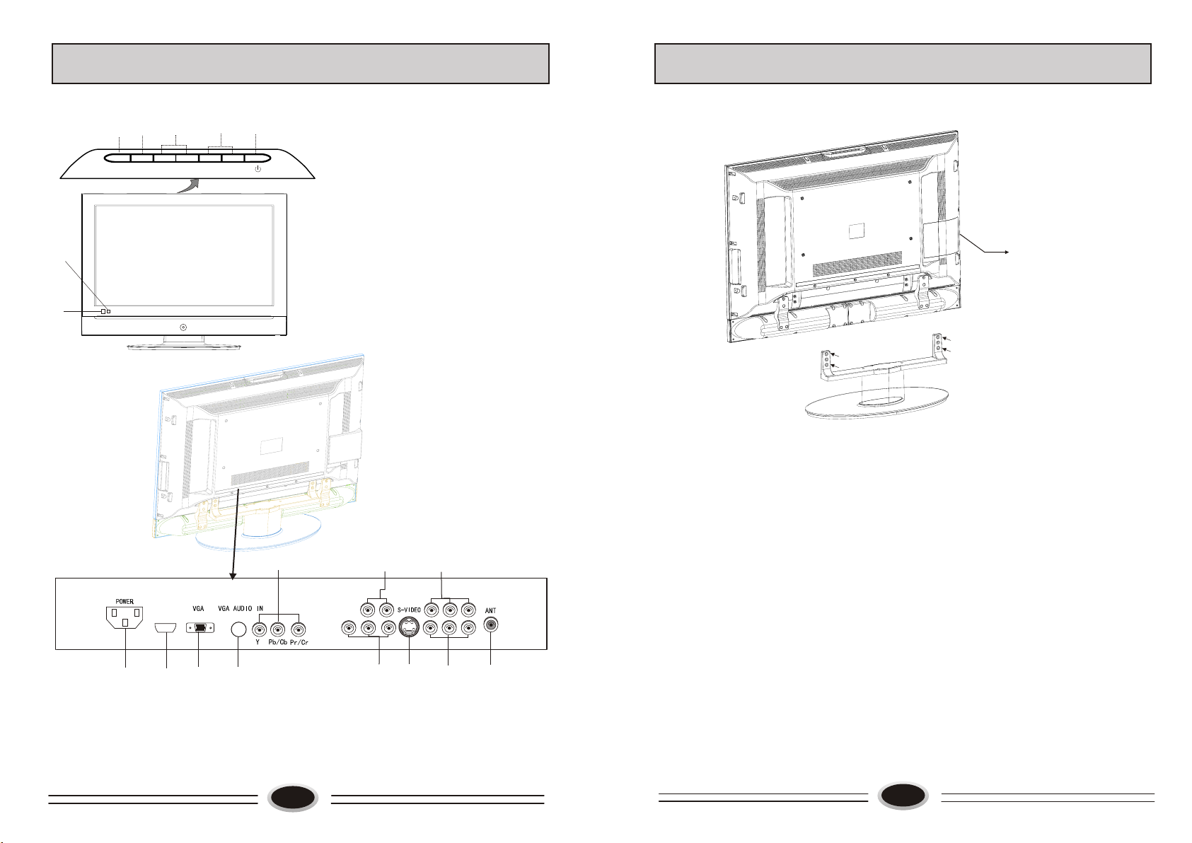
BASE DISASSEMBLY/ASSEMBLY METHOD
1
MEN U
6
7
Back interface
3
2
CH-TV/ AV
CH+
VOL - VOL +
5
4
Menu button
1.
TV/AV switch button
2.
Program down/up button
3.
Volume down/up button
4.
Power button
5.
Power indicator
6.
Remote sensor
7.
Complete set
(1)As figure, removing the four M4×20 screws, the base will be disassembled.
(2)As figure, mounting the four M4×20 screws, the base will be assembled.
8
HDMI
11
1
10
9
AV-OUT
6
L-AUDIO IN-R
L-AUDIO OUT-R
3
AV2 L-AUDIO2 IN-R
AV1 L-AUDIO1 IN-R
457
1. Power input socket 2. Antenna input
3. AV2 input 4. AV1 input
5. S-VIDEO input 6. YPbPr or S-VIDEO audio input
7. AV output 8. YPbPr input
9. VGA audio input interface 10. VGA input
11.HDMI input
5
Note:
The arrow indicates the position of screw.
2
6
Page 5

PREPARATION FOR REMOTE CONTROL
Remote control installation
1. According to the figure display below, place the remote control with face down,
then open the cover of battery apartment.
2. As in the figure display below, install two AA batteries. (The + and - symbol of
battery must match with the marks on the remote).
3.Close the cover of battery apartment.
1
Cautions for using remote control
Confirm there is no object between the
remote control and the remote sensor
of TV set.
Do not put the remote control in direct
heat or a damp place, or potential
damage to the remote may occur.
2
++
3
Sunshine or other strong light will
interfere the signal sent by the remote
control. In this situation turn the TV
set to avoid the direct light source.
Please use two AA 1.5V batteries.
Do not mix battery types.
Install the batteries as the correct
polarities.
Do not use the rechargeable batteries.
REMOTE CONTROL PANEL
Buttons and Descriptions
MUTE
2
3
MAIN/SUB
7
6
1 2 3
4
7
CHILD LOCK
11
P.STD
12
14
17
25
20
21
22
VOL-
C.SYS
↑
↓
STILL SCAN
=
TV/AV
PIP
SLEEP
SOUND
AAA
5
8 9
0
CH+
MENU
CH-
I-II
SIZE
POWER
DISPLAY
6
RECALL
S.STD
VOL+
S.SYS
←
→
←
BACKZOOM
Power button
1
1
2
8
4
5
9
10
13
15
16
18
26
27
19
24
23
Mute button
3
TV/AV switch button
4
Display button
5
Dynamic AAA HDTV on/off button
6
PIP function on/off button
7
PIP main/sub picture switch button
8
PIP sound selection button
9
One digit selection button
10
Program recall button
11
Child lock button
12
Picture mode selection button
11
Sound mode selection button
13
14
Program up/down button, direction
selection button
Volume up/down button, direction
15
selection button
Menu call/selection button
16
Color system selection button
17
Sound system selection button
18
19
Program scan button
20
Picture still button
21
This function is not available
Picture size selection button
22
Sleep timer button
23
This function is not available
24
25
This function is not available
Nicam button
26
27
This function is not available
7
H YF - 3 5R
8
Page 6

BASIC OPERATION
SCREEN DISPLAY
MUTE
MAIN/SUB
TV/AV
PIP
SOUND
AAA
POWER
DISPLAY
POWER ON/OFF TV
Standby set: first connect the power supply wire,
then turn the power switch on the top of TV set on.
1. If the TV set is in standby status, pressing power
switch on the remote control or TV set can
cancel the standby status, then enter the power on
status.
2. Pressing power switch on the remote control or
the TV set again, the TV set will enter standby
status.
TV PROGRAM SELECTION AND VOLUME
ADJUSTMENT
You can use CH+/- button or direct-digit choosing
button to select the TV channel number.
Press VOL+/- button to adjust the volume.
RECALL
Pressing RECALL button can switch the channel to the
last channel you watched.
MUTE FUNCTION
1. Press MUTE button to shut off the TV sound, the
screen displays mute mark.
2. Press MUTE button again or VOL+ button to turn
on the TV sound.
For your convenient operation and in order to know the TV set, we offer the below
menus.
Picture setting menu
PICTURE
PICTURE MODE PERSONAL
CONTRAST
BRIGHTNESS
SATURATION
TINT
SHARPNESS
NOISE REDUCE
SIZE MODE
MOVE SELECT MENU EXIT
STRONG
FULL
Sound setting menu
SOUND SOURCE MAIN
SOUND MODE NEWS
BALANCE
EQUALIZER
SOUND
MOVE SELECT MENU EXIT
Source setting menu
SOURCE
PICTURE SOURCE TV
PIP MODE OFF
SUB PICTURE VGA
COLOR SYSTEM AUTO
SOUND SYSTEM
AUTO SEARCH
MANUAL SEARCH
MOVE SELECT MENU EXIT
BG
Menu setting menu
OSD
LANGUAGE ENGLISH
H-POSITION
V-POSITION
DURATION
TRANSPARENCY
MOVE SELECT MENU EXIT
Function setting menu
FUNCTION
CLOCK 00:12
TIME ON --:-TIME OFF --:-SLEEP TIMER OFF
COLOR TEMP USER
D FILTER
AAA ON
OSD
LANGUAGE ENGLISH
H-POSITION
V-POSITION
DURATION
TRANSPARENCY
MOVE SELECT MENU EXIT
OSD LANGUAGE SELECTION
Select the LANGUAGE item in the menu.
1.Press MENU button to make the main menu display.
2.Press CH+/- button to select OSD menu.
3.Press VOL+/- button enter the OSD menu.
4. Press CH+/- button to select LANGUAGE item.
5. Press VOL+/- button to select the language you need.
9
MOVE SELECT MENU EXIT
Operation instructions
The real display may be different from the above menus, if you need adjust, please do as
follows:
1.Press MENU button to open the menu, use CH+/- button to select every menu
separately, use VOL+/- button to enter.
2.Press CH+/- button to select the item needs adjust.
3.Press VOL+/- button to adjust the selected item, or enter the next menu.
4.Press MENU button to return the last menu or exit the screen menu display.
Note: “press MENU button to select the menu ”operation in the user’s manual, please
refer to these operation instructions.
10
Page 7

TV PROGRAM SETTING
TV PROGRAM SETTING
SOURCE
PICTURE SOURCE TV
PIP MODE OFF
SUB PICTURE VGA
COLOR SYSTEM AUTO
SOUND SYSTEM
AUTO SEARCH
MANUAL SEARCH
MOVE SELECT MENU EXIT
SOURCE
CURRENT CHANNEL 10
SKIP OFF
TARGET CHANNEL 10
EXCHANGE
AFC OFF
FINE TUNE
SEARCH NEXT 471.2MHZ
MOVE SELECT MENU EXIT
BG
AUTO SEARCH
Using AUTO SEARCH can search all receiving
programs. We recommend using auto search to
search the program when you use this TV set for
the first time, before auto search, please confirm
the sound system is BG or DK.
1.Press MENU button to make the main menu display.
2.Press CH+/- button to select SOURCE menu.
3.Press VOL+/- button enter the SOURCE menu.
4.Press CH+/- button to select AUTO SEARCH.
5.Press VOL+/- button to start searching, press MENU
button to finish auto search.
Note: The order of the auto search is due to the
frequency of the program, generally speaking,
it is used only at the first time you search the
program, and once the order of the program has
been confirmed, you don’t have to use this
function, otherwise the order of the program
will be changed.
MANUAL SEARCH
Manual search can search and order the program freely.
1.Press MENU button to make the main menu display.
2.Press CH+/- button to select SOURCE menu.
3.Press VOL+/- button enter the SOURCE menu.
4. Press CH+/- button to select MANUAL SEARCH,
press VOL+/- button to enter the next menu.
5. Press CH+/- button to select SEARCH NEXT.
6. Press VOL+/- button to start searching, pressing
VOL+ button is used to search the higher frequency
channel, pressing VOL- button is used to search the
lower frequency channel, when you have searched
a program, the searching will stop automatically.
You can press VOL+/- button to go on searching or
press MENU button to exit.
Note: During searching, it may appear black screen
because of change of signal, it is normal, it will
recover after finishing searching.
11
FINE TUNE
When you can’t get a satisfactory picture effect,
you can fine tune to obtain.
1.Press MENU button to make the main menu display.
2.Press CH+/- button to select SOURCE menu.
3.Press VOL+/- button enter the SOURCE menu.
4.Press CH+/- button to select MANUAL
SEARCH, press VOL+/- button to enter the next
menu.
5. Press CH+/- button to select FINE TUNE.
6. Press VOL+/- button to start fine tune until you
obtain the best picture and sound, then loose
the button, press MENU button to exit.
SKIP
1. Select the program number you need skip.
2.Press MENU button to make the main menu display.
3.Press CH+/- button to select SOURCE menu.
4.Press VOL+/- button enter the SOURCE menu.
5. Press CH+/- button to select the MANUAL
SEARCH, press VOL+/- button to enter the
next menu.
6. Press CH+/- button to select SKIP, press
VOL+/- button to select ON.
7. Press MENU button to shut off the menu.
When you use CH+/- button to select channel,
this channel number will be skipped. But you
can still use one direct-digit choosing button to
select the skipped channel number.
Note: How to recover the skipped channel number
1. Press direct-digit choosing button to select the
channel number that needs recover.
2.Press MENU button to make the main menu display.
3.Press CH+/- button to select SOURCE menu.
4.Press VOL+/- button enter the SOURCE menu.
5. Press CH+/- button to select the MANUAL
SEARCH, press VOL+/- button to enter the
next menu.
6. Press CH+/- button to select SKIP, press
VOL+/- button to select OFF.
12
SOURCE
CURRENT CHANNEL 10
SKIP OFF
TARGET CHANNEL 10
EXCHANGE
AFC OFF
FINE TUNE
SEARCH NEXT 471.2MHZ
MOVE SELECT MENU EXIT
SOURCE
CURRENT CHANNEL 10
SKIP OFF
TARGET CHANNEL 10
EXCHANGE
AFC OFF
FINE TUNE
SEARCH NEXT 471.2MHZ
MOVE SELECT MENU EXIT
SOURCE
CURRENT CHANNEL 10
SKIP OFF
TARGET CHANNEL 10
EXCHANGE
AFC OFF
FINE TUNE
SEARCH NEXT 471.2MHZ
MOVE SELECT MENU EXIT
Page 8

TV PROGRAM SETTING
IMAGE CONTROL
SOURCE
CURRENT CHANNEL 15
SKIP OFF
TARGET CHANNEL 28
EXCHANGE
AFC OFF
FINE TUNE
SEARCH NEXT 471.2MHZ
MOVE SELECT MENU EXIT
PICTURE
PICTURE MODE PERSONAL
CONTRAST
BRIGHTNESS
SATURATION
TINT
SHARPNESS
NOISE REDUCE
SIZE MODE
MOVE SELECT MENU EXIT
PICTURE
PICTURE MODE PERSONAL
CONTRAST
BRIGHTNESS
SATURATION
TINT
SHARPNESS
NOISE REDUCE
SIZE MODE
MOVE SELECT MENU EXIT
STRONG
FULL
STRONG
FULL
EXCHANGE
1.Press MENU button to make the main menu display.
2.Press CH+/- button to select SOURCE menu.
3.Press VOL+/- button enter the SOURCE menu.
4.Press CH+/- button to select MANUAL SEARCH,
press VOL+/- button to enter the next menu.
5.Press CH+/- button to select TARGET CHANNEL,
press VOL+/- button to select the channel you need
exchange.
6.Press CH+/- button to select EXCHANGE, press
VOL+/- button to exchange, as figure, exchange
the current channel number 15 to channel number 28.
7. Press MENU button to save and exit.
Note: Please shut off the connected but not used signal
source in order not to affect normal watching.
IMAGE CONTROL
SET YOUR FAVOURITE PICTURE MODE
SET YOUR FAVOURITE PICTURE MODE
1.Press MENU button to make the PICTURE menu
display.
2.Press VOL+/- button enter the PICTURE menu.
3.Press CH+/- button to select the item that needs
adjust.
4. Press VOL+/- button to adjust the selected item,
the detailed adjustment is as following table.
The table of picture item adjustment effect
Items
Contrast
Brightness
Saturation
Tint
*
Sharpness
VOL- VOL+
Weak
Dark
Light
Green
Strong
Bright
Thick
Red
Soft Sharp
Note: TINT is only valid in N system.
NOISE REDUCE
Noise reduce can decrease the noise of picture
1.Press MENU button to make the PICTURE menu
display.
2.Press VOL+/- button enter the PICTURE menu.
3.Press CH+/- button to select the NOISE REDUCE.
4.Press VOL+/- button to select OFF, WEAK or
STRONG as your require.
13
PICTURE MODE/SOUND MODE SELECTION
Press P.STD button on the remote control
continually, the following four picture modes
can be selected in turn.
NATURAL
BRIGHT PERSONAL SOFT
NATURAL: common mode.
SOFT: the image effect is soft.
USER: set the image effect you like.
BRIGHT: suitable for sport image.
Press S.STD button on the remote control
continually, the following four sound modes
can be selected in turn.
NORMAL
MUSIC PERSONAL
NEWS
You can also enter picture and sound menu to adjust.
SOUND CONTROL
SOUND EFFECT CONTROL
You can select your favourite sound modes, and adjust
the BALANCE and EQUALIZER of sound.
1. Press MENU button to make the main menu display.
2. Press CH+/- button to select the SOUND menu.
3. Press VOL+/- button to enter the SOUND menu.
4. Press CH+/- button to select the sound item you need set.
5. Press VOL+/- button to adjust the selected item.
BALANCE: Press VOL+/- button to enter adjustment,
use VOL+/- button to adjust the balance of left and
right sound.
EQUALIZER: Press VOL+/- button to enter EQUALIZER
set menu, use VOL+/- button to select every different
frequency, use CH+/- button to adjust.
Note: Sound source only can be adjusted in PIP mode.
SYSTEM SETTING FUNCTION
OSD BACKGROUND SETTING
The higher of the transparency set value is,
the higher of the OSD transparency is, whereas,
the transparency is lower.
1.Press MENU button to make the main menu display.
2.Press CH+/- button to select OSD setting menu.
3.Press VOL+/- button to enter the OSD menu.
4.Press CH+/- button to select the TRANSPARENCY item.
5.Press VOL+/- button to set the transparency value.
14
CHILD LOCK
P.STD
CHILD LOCK
P.STD
RECALL
0
S.STD
RECALL
0
S.STD
SOUND
SOUND SOURCE MAIN
SOUND MODE NEWS
BALANCE
EQUALIZER
SOUND
移动 选择 菜单 退 出
MOVE SELECT MENU EXIT
50
75 100 300 1K 3K 5K 10K 15K
SELECT MENU EXIT
MOVE
OSD
LANGUAGE ENGLISH
H-POSITION
V-POSITION
DURATION
TRANSPARENCY
MOVE SELECT MENU EXIT
TRANSPARENCY
SELECT MENU EXIT
MOVE
63
Page 9

SYSTEM SETTING FUNCTION
OTHER SETTING FUNCTION
SOURCE
PICTURE SOURCE TV
PIP MODE OFF
SUB PICTURE VGA
COLOR SYSTEM AUTO
SOUND SYSTEM
AUTO SEARCH
MANUAL SEARCH
MOVE SELECT MENU EXIT
PICTURE
PICTURE MODE PERSONAL
CONTRAST
BRIGHTNESS
SATURATION
TINT
SHARPNESS
NOISE REDUCE
SIZE MODE
MOVE SELECT MENU EXIT
BG
STRONG
FULL
OTHER SETTING FUNCTION
FUNCTION
CLOCK 00:12
TIME ON --:-TIME OFF --:-SLEEP TIMER OFF
COLOR TEMP USER
D FILTER
AAA ON
MOVE SELECT MENU EXIT
SIGNAL SOURCE SETTING
There is different signal source mode in this TV set,
you can select according to your require: TV,
AV1, AV2, S-VIDEO, YPBPR, VGA, HDMI.
1.Press MENU button to make the main menu display.
2.Press CH+/- button to select SOURCE menu.
3.Press VOL+/- button enter the SOURCE menu.
4
.Press CH+/- button to select PICTURE SOURCE
item.
5.Press VOL+/- button to select the signal source
mode you need.
6.You can press TV/AV button on the remote
control to select directly.
SCREEN DISPLAY PICTURE ZOOM SETTING
There is different screen display picture zoom,
you can select according to your require: FULL,
ZOOM1, ZOOM2, NORMAL.
1.Press MENU button to make the PICTURE menu
display.
2.Press VOL+/- button enter the PICTURE menu.
3.Press CH+/- button to select SIZE MODE.
4.Press VOL+/- button to select the zoom you need.
5.You can press ZOOM button on the remote control
to switch.
SLEEP TIMER SETTING
After you set the sleep timer, the TV set will count
from the setting time, when the count time is coming,
the TV set will turn off automatically.
Press SLEEP button to enter off time set, you can
select the certain time: OFF, 15Min, 30Min, 60Min...
240Min, after setting, the TV set will start counting.
Note: if you want to see the off time you set, press
SLEEP button. If you want to cancel the sleep time
set, follow the above procedures, set the time OFF.
15
PIP SETTING
This TV set support PIP function, it can display
picture of two sources at the same time.
1.Press MENU button to make the main menu display.
2.Press CH+/- button to select SOURCE menu.
3.Press VOL+/- button enter the SOURCE menu.
4 Press CH+/- button to s
. elect PIP mode, press VOL+/ button to select P1S1, P1S2, P2S1, P2S2, P3S1, P3S2,
P4S1or P4S2 mode, open PIP function.
Press CH+/- button to s
5. elect PICTURE SOURCE, press
VOL+/- button to change the input source of main picture,
such as TV, AV1, AV2 and so on.
Press CH+/- button to s
6. elect SUB PICTURE source, press
VOL+/- button to change the input source of sub picture,
such as VGA, YPBPR, HDMI and so on.
Note:
1. After switching the main picture source, it will
shut off the PIP function, if need, you can open
this function again.
2. The following two suit
can use PIP function,
the same suit source
can not use PIP
SOURCE1
SOURCE2
TV, AV1, AV2, S-VIDEO
VGA, YPBPR, HDMI
function, source1
and source2 can switch.
3.You can press PIP button on the remote control
to turn on or turn off the PIP function.
4.You can press MAIN/SUB button on the remote
control to switch the main picture and sub picture.
SOUND SOURCE SETTING
After the PIP function is open, this item is activated,
you can select the main picture sound or sub picture
sound of current broadcasting sound.
1.Press MENU button to make the main menu display.
2.Press CH+/- button to select SOUND menu.
3.Press VOL+/- button enter the SOUND menu.
4.Press CH+/- button to select SOUND SOURCE.
5.Press VOL+/- button to change the current sound to
main picture sound or sub picture sound.
Note:
1.You can also press SOUND button on the remote
control to switch the main picture sound or sub
picture sound.
2.After switching the sound to sub picture sound, you
can switch the source in sub picture.
16
SOURCE
PICTURE SOURCE TV
PIP MODE OFF
SUB PICTURE VGA
COLOR SYSTEM AUTO
SOUND SYSTEM
AUTO SEARCH
MANUAL SEARCH
MOVE SELECT MENU EXIT
SOUND SOURCE MAIN
SOUND MODE NEWS
BALANCE
EQUALIZER
SOUND
MOVE SELECT MENU EXIT
BG
Page 10

OTHER SETTING FUNCTION
OTHER SETTING FUNCTION
FUNCTION
CLOCK 00:12
TIME ON --:-TIME OFF --:-SLEEP TIMER OFF
COLOR TEMP USER
D FILTER
AAA ON
MOVE SELECT MENU EXIT
FUNCTION
CLOCK 00:12
TIME ON --:-TIME OFF --:-SLEEP TIMER OFF
COLOR TEMP USER
D FILTER
AAA ON
MOVE SELECT MENU EXIT
FUNCTION
CLOCK 00:12
TIME ON --:-TIME OFF --:-SLEEP TIMER OFF
COLOR TEMP USER
D FILTER
AAA ON
MOVE SELECT MENU EXIT
COLOR TEMPERATURE
1.Press MENU button to make the main menu display.
2.Press CH+/- button to select FUNCTION menu.
3.Press VOL+/- button enter the FUNCTION menu.
4.Press CH+/- button to select COLOR TEMP.
5.Press VOL+/- button to select DEFAULT→ 6500K→
→7300K→8500K→9300K→USER
Note: PERSONAL is the color temperature of picture
you set through D FILTER.
DIGITAL FILTER SETTING
Use D FILTER can adjust the color temperature
exactly.
1.Press MENU button to make the main menu display.
2.Press CH+/- button to select FUNCTION menu.
3.Press VOL+/- button enter the FUNCTION menu.
4.Press CH+/- button to select D FILTER.
5.Press VOL+/- button to select the COLOR TEMP,
use CH+/- button to adjust.
AAA SETTING
AAA function can improve the quality of picture and
make the picture best.
1.Press MENU button to make the main menu display.
2.Press CH+/- button to select FUNCTION menu.
3.Press VOL+/- button enter the FUNCTION menu.
4.Press CH+/- button to select AAA.
5.Press VOL+/- button to select ON, OFF, DEMO or
SPLIT.
6.Press AAA button on the remote control to start
and select AAA mode.
DEMO: Use one moved sub picture in the picture to
start AAA function.
SPLIT: Separate the picture from left and right, start
AAA function in left picture.
Note: It can not use the DEMO, SPLIT function with
no signal and in PIP mode.
- HDMI . The HDMI logo and High-Definition Multimedia Interface is a trademark
TM
or registered trademark of HDMI Licensing.
-This TV can receive the High-Definition Multimedia Interface (HDMI).
-This TV supports HDCP (High-bandwidth Digital Contents Protection) Protocol for
720x480p, 1280x720p and 1920x1080i resolution.
-When you connect this TV with a source device (DVD player, Set Top Box or PC)
supporting Auto HDMI function, the output resolution of the source device will be
automatically set to 1280x720p.
-If the source device does not support Auto HDMI, you need to set the output
resolution appropriately.
To get the best picture quality, adjust the DVD Player or Set Top Box’s output resolution
to 1280x720p, and the PC graphics card’s output resolution to 1024x768, 60Hz.
-If the source device has an HDMI output, no other audio connection is necessary
because HDMI-to-HDMI connecting includes both video and audio.
How To Connect
1. Connect the source device to HDMI port of this TV with an HDMI cable (not
supplied with this product).
2. No separate audio connection is necessary.
How To Use
-If the source device supports Auto HDMI function, the output resolution of the source
device will be automatically set to 1280x720p.
-If the source device does not support Auto HDMI, you need to set the output resolution
appropriately.
To get the best picture quality, adjust the output resolution of the source device to
1280x720p.
-Select HDMI input source by using TV/AV button.
How To Set
The method to set is similar to TV.
17
18
Page 11

EXTERNAL AUDIO AND VIDEO EQUIPMENT CONNECTION
USING YOUR TV AS A COMPUTER DISPLAY
You can connect outside signal source VCR VCD
DVD PC equipment to the TV set.
Antenna Input
1.Connect the VCR radio frequency input to
the back radio frequency input of the LCD.
2. Connect the antenna to VCR antenna input.
3. Press TV/AV button to select TV mode.
4. Press PLAY button in VCR to start watching.
AV input
1.Connect audio video output port in VCD to
AUDIO IN and VIDEO IN port in TV set.
2. Press TV/AV button to select composite
VIDEO mode.
3. Press PLAY button in VCD to start watching.
S-VIDEO input
If you use S terminal as signal input source,
the image quality will be better than video(AV).
1.Connect S terminal output in DVD to S terminal
input in TV set.
2.Connect S terminal left/right audio output in DVD to
the relevant port in TV set.
3.Press TV/AV button repeatedly until the display
mode is S-VIDEO.
4.Press PLAY button in DVD to broadcast. At this time
the image programs in DVD will broadcast in TV set.
LL
AUD IO IN
L
AUD IO IN
VGA input
1. Connect the VGA output port in the computer to the VGA port in the TV set.
2. Connect the audio cable in computer to VGA AUDIO IN port in TV set.
ANT .
3. Press TV/AV button to select VGA mode.
4. Turning on the computer, the screen image of the computer will display on the
TV set.
VCR
RR
S-V IDEO
VIDEO IN
IN
VCD
At this time, the TV set can be used as a computer display.
VG A
VG A-A UD IO IN
RESOLUTION:
R
S-V IDEO
VIDEO IN
IN
Mode
VGA
DVD
SVGA
Resolution
640 x 480
800 x 600
Frequency
31.5kHz
37.9kHz
Horizontal
Vertical
Frequency
60Hz
60Hz
DTV input
1. Component terminal (Y/PbCb/PrCr) connect to the
component output of picture output device (such as
DVD, HDTV TUNER and so on ), the sound is input
from AUDIO IN:
2.Press TV/AV button to select HDTV mode.
3.Press PLAY button on the external device to start
watching.
HDMI input
1.Connect HDMI signal source output to the HDMI
input in this TV set.
2.Press TV/AV button to select HDMI mode.
3.Press PLAY button on the external device to start
watching.
19
LL
AUD IO IN
RR
DVD
HDMI
DVD
Y Cb/ Pb Cr/P r
XGA
1024 x 768
48.4kHz
60Hz
Note: The above parameters are VESA standard.
Note:
1. If the temperature of the TV set is rather low, it is normal that there may be some
artifacts when the set is first turned on.
2. Nonconforming pixels may occur on the panel, but they have no influence on the
normal function of the display.
3. In the standard operation, It is normal if there is one bright dot or dark dot on the
screen.
20
Page 12

SPECIFICATIONS
TROUBLE SHOOTING GUIDE
The part specifications of this TV set provided here are for reference only.
Difference may occur as product technology is updated.
Model
Screen
TV/VIDEO
Type
Viewable angle
Color system
Sound system
Video input
DTV Y/Pb/Pr
Power
Power consumption
Dimension (W×D×H)(cm)
Environment conditions
Accessory
A-si TFT active m atrix
176°(H) /176° (V)
PAL, SECAM, NTSC (AV)
BG, DK
CVBS, S-VHS, YPb/Pr, YCb/Cr, VGA,HDMI
Composite: 480i/p, 576i, 720p,1080i,1080p
See rating plate
See rating plate
93.7×31.2×70.5 (included base)
Working temperature:
Working humidity:
Storage temperature:
Storage humidity:
User’s manual (×1)
Remote control (×1)
Power cord (×1)
Battery (×2)
L37A9 A-A
+5℃~+35℃
20%-80%
-15℃~+45℃
5%-90%
The following problems are not always caused by hardware failure, please use the
follow trouble shooting guide before you call for service:
BREAKDOWN PHENOMENON
CHECK FOR
PICTURE
Picture with S now
SOUND
The direction and connection of the
antenna
Noise
Direction, station and connection
Double or Triple Image
Normal
of the antenna
Interference from electric
appliance. Automobile、Motor,
Disturb
Noise
Vehicle Fluorescence lamp etc.
Volume, Sound mute
Normal
?
??
No Picture
No Sound
No Sound
The power plug isn't plugged in AC
outlet. The main power isn't turned
on. The setting up of contrast, brightness and volume.
Adjust color control
No Color
Normal Volume
Adjust channel again
Scramble
Normal or Weak Volume
The design and specifications are subject to change without notice.
21
Note:1.If the problem can not be fixed after you check above items. DO NOT attempt
to remove the back cover by yourself.
2.A snapping sound from the cabinet of the TV set can be heard occasionally.
This is normal and is caused by temperature changes of the operating environment
and does not affect the operation of the set.
3.Do not let the TV set stay on a static images, as this can lead to permanent
residual images. If this situation occurs, the TV set may recover normal
automatically after 12 hours if you switch the TV set to dynamic programming.
22
 Loading...