

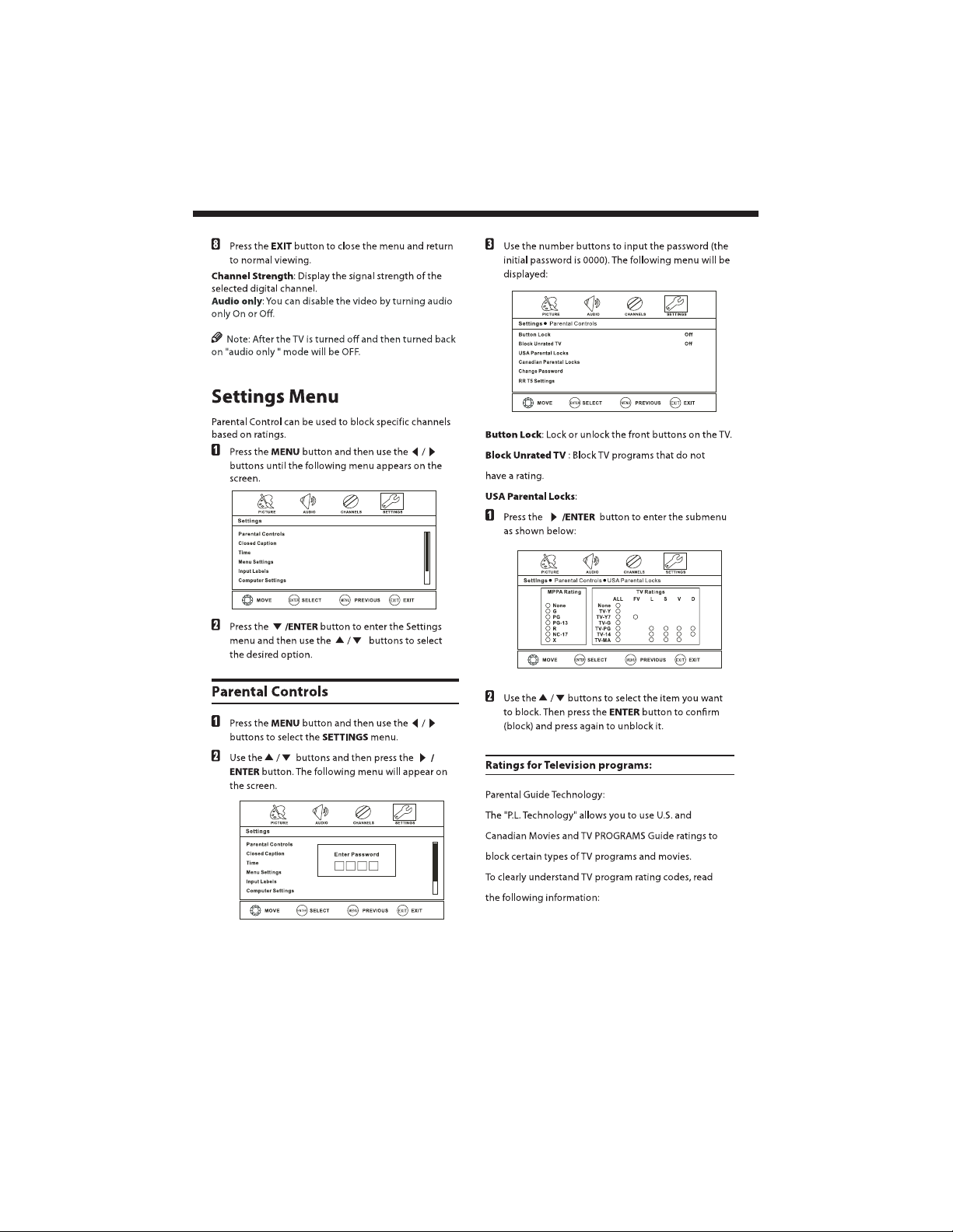
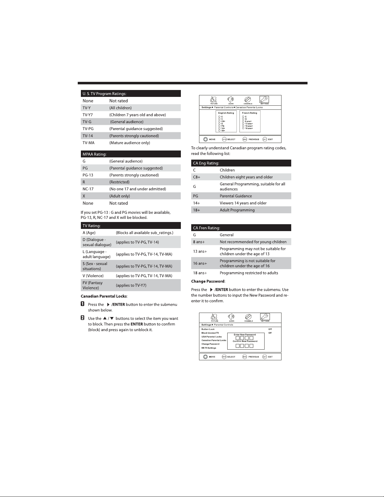
Page 1

L32D1120
L32F1120
Page 2

Contents
Safety and warnings.......................................................................................2-3
Introduction..................................................................................................4
Stand installation guide..................................................................................5
Installation....................................................................................................6-9
Remote Control............................................................................................10
Operation..................................................................................................... 11-22
Trouble Shooting...........................................................................................2 3
Warranty.......................................................................................................24
-1-
Page 3
SAFETY AND WARNINGS
IMPORTANT SAFETY INSTRUCTION
1) Read these instructions.
2) Keep these instructions.
3) Heed all warnings.
4) Follow all instructions.
5) Do not use this near water.
Television
6) Clean only with dry cloth.
7) Do not block any ventilation openings, install in
accordance with the instructions.
8) Do not install near any heat sources such as
radiations, heat registers, stoves, or other
Television
9) Do not defeat the safety purpose of the polarized
plug. If the provided plug does not fit into your outlet,
consult an electrician for replacement of the
obsolete outlet.
10) Protected the power cord from being walked on
or pinched particularly at plugs, convenience
receptacles, and the point where they exit from the
Television.
11) Only use attachments/accessories specified by
the manufacturer.
12) Unplug this during lighting storms or
when unused for long periods of time.
13) Refer all servicing to qualified service
personnel. Servicing is required when the
Television
power-supply cord or plug is damaged, liquid has
been spilled or objects have fallen into the
Television Television
or moisture, does not operate normally, or has been
dropped.
14) Mains plug is used as the disconnect device, the
disconnect device shall remain readily operable.
15) The ventilation should not be impeded by
covering the ventilation openings with items, such
as newspapers, table-cloth, curtains, etc.
16) No naked flame sources, such as lighted
candles, should be placed on the .
17) Attention should be drawn to the environmental
aspects of battery disposal.
18) The use of in moderate climate.
19) The shall not be exposed to dripping
or splashing and that no objects filled with liquids,
such as vases, shall be placed on the .
TO REDUCE THE RISK OF ELECTRIC SHOCK, DO
NOT REMOVE COVER (OR BACK).NO USER
SERVICEABLE PARTS INSIDE. REFER SERVICING
TO QUALIFIED SERVICE PERSONNEL.
(including amplifiers) that produce heat.
Television
has been damaged in any way, such as;
, the has been exposed to rain
Television
Television
Television
Television
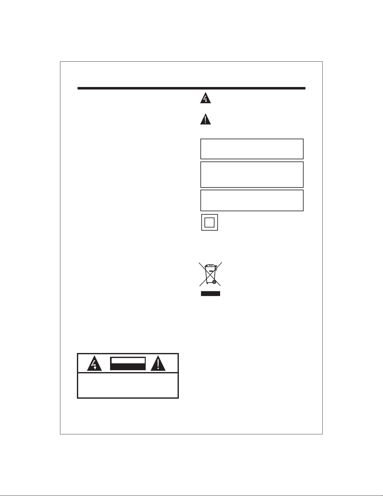
CAUTION
RISK OF ELECTRIC SHOCK
DO NOT OPEN!
CAUTION
The symbol indicates that dangerous voltages
constituting a risk of electric shock are present
within this unit.
The symbol indicates that there are important
operating and maintenance instructions in the
literaturaccompanying this unit.
WARNING:
To reduce the risk of fire or electric shock, do
not expose this to rain or moisture.Television
WARNING:
The batteries shall not be exposed to
excessive heat such as sunshine, fire or the
like.
WARNING:
The excessive sound pressure from earphones
and headphones can cause hearing loss.
This symbol indicates that this product
incorporates double insulation between
hazardous mains voltage and user accessible
parts. When servicing use only
identical replacement parts.
This marking indicates that this product should
not be disposed with other household wastes
throughout the EU. To prevent possible harm to
the environment or human health from
uncontrolled waste disposal, recycle it
responsibly to promote the sustainable reuse of
material resources. To return your used device,
please use the return and collection systems or
contact the retailer where the product was
purchased. They can take this product for
environmental safe recycling.
Haier is committed to safely recycling electronic
products and product materials. Please check
for a local recycling location in the United States
at: 1800RECYCLING.COM or call
1.800.RECYCLING.
-2-
Page 4
SAFETY AND WARNINGS
High voltages are used in the operation of this television
receiver. Do not the cabinet.
Refer servicing to qualified service personnel.
To prevent fire or electrical shock hazard, do not expose
the television receiver to rain or moisture.
Do not drop or push objects into the television cabinet
slots or openings. Never spill any kind of liquid on the
television receiver.
Do not block the ventilation holes on the back cover
. Adequate ventilation is essential to prevent
the TV
failure of electrical components.
open
of
Never stand on, lean on, or suddenly push the television or
its stand. You should pay special attention to children.
Serious injury may result if it falls.
Do not place your television on an unstable cart, stand,
shelf or table. Serious injury to an individual and
damage to the television may result if it falls.
When the television receiver is not used for an
extended period of time, it is advisable to disconnect
the AC power cord from the AC outlet.
Avoid exposing the television receiver to direct sunlight
and other sources of heat. Do not stand the television
receiver directly on other products which give off heat,
e.g. video cassette players and audio amplifiers. Do not
place naked flame sources, such as lighted candles on
the television.or near
/or
Do not trap the power supply cord under the television
receiver s .' stand
Dim:515*320mm(
If the television is to be built into a compartment or
similar enclosure, the minimum distances must be
maintained. Heat build-up can reduce the life of your
television, and can also be dangerous.
-3-
Page 5
Main features
Integrated ATSC TV tuner for HDTV broadcast
reception
High brightness provides a vivid and brilliant
picture
Deeper blacks and brighter whites with high
contrast
Wide Screen aspect ratio (16:9) for a complete
home theater experience
HDMI input for true digital connection
VGA port for connection to PC
Built-in stereo speaker system
Full-function Remote Control
Main parameter
INTRODUCTION
Accessories
Accessories
Power Cable.....................................
Infrared Remote Control....................
User s Manual .................................
Battery(AAA)................................... 2
1
1
1
Viewing Picture Size (diagonal)
Resolution:
Power consumption:
Audio Output Power (THD 7%):
Input Power Voltage:
Aspect Ratio:
TV System:
Video Signal System:
Receiving Channel:
High-Definition Multimedia Interface (HDMI) Input
Component (YPbPr) Video Input
Composite Video Input
Analog RGB (VGA) Input
Audio Input x 3
Headphone Output
Coaxial Output
USB Input
Horizontal definition (TV line)
32 inches
1366x768
135W
2x8W
AC 100V-240V 50/60Hz
16:9
ATSC Digital system and NTSC Analog system
NTSC
Cable :1-135/ Air: 2-69 (ATV&DTV)
x2
x1
x2
x1
x1
x1
x1
Composite Video Input >=350
Video Input >=400
Component (YPbPr) Video Input >=400
-4-
Page 6
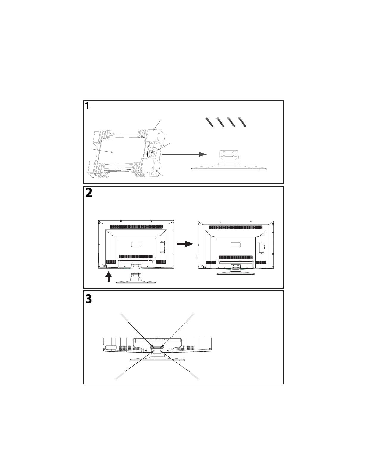
This STAND INSTALLATION GUIDE is provided to help you easily install the stand. Please carefully follow
Steps 1 through 3.
Open the box and find the parts
STAND INSTALLATION GUIDE
Open the box and find the following parts.
- Stand x1 pc
- Screwsx4pcs
Packing
Screws
Stand
TV
Stand
Packing
Place the Stand on the TV
1. Place the TV face down on a soft and flat
surface (blanket, foam, cloth, etc.) to
prevent any damage to the TV.
2. Place the Stand on the TV as shown below.
Stand
Secure the Stand to the TV
Secure the Stand to the TV by using the 4 supplied screws.
12
43
-5-
Page 7
INSTALLATION
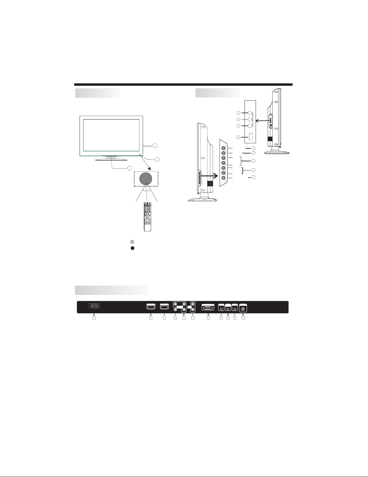
Front panel
3
1
2
30 30
1: Remote control sensor.
2: Indicator LED: GREEN POWER ON.
RED STANDBY.
3: Side panel keys
Side panel
R
9
L
AV2
8
Video
7
6
USB
SOURCE
MENU
CH+
CHVOL+
VOL-
STANDBY
1. SOURCE:
2. MENU:
3. CH+/CH-:
change the channel up and down. In MENU mode,
press "CH+" or "CH-" to select items in standby
mode, press "CH+" or "CH-" to turn on the TV.
4. VOL+/VOL-:
press "VOL+ " or "VOL- " to adjust the item that
you selected.
5. STANDBY:
from STANDBY mode. Press it again to turn the set
back to STANDBY.
6. USB INPUT
7. VIDEO INPUT
8. AUDIO INPUT-L
9. AUDIO INPUT-R
Display the input source menu.
Display the main MENU.
In TV mode, press "CH+" or "CH-" to
Adjust sound level. In MENU mode,
Press this button to turn the unit ON
1
2
3
4
5
REAR AV INPUT/OUTPUT
HDMI2
ACINPUT
100-240V~50/60Hz
HDMI1
1 2
1. HDMI1 Input
2. HDMI2 Input
3. Composite Video Input
4. Component Video (YPbPr) Input
5. Audio Input
Pb
Pr
AV1
3
COMPONENT
INPUT
AUDIO
INPUT
Y
4 5
L
R
7. Headphone Output
8. PC Audio Input
9. Coaxial
10. Antenna Socket
11. AC Power Socket
6. VGA Port (PC Input)
Note: 1. Composite video input and component video input share the audio input.
2. When HDMI1 has an input signal coming from a DVI source then the audio input signal
must be connected to the PC audio input.
3. When HDMI2 has an input signal coming from a DVI source then the audio input signal
must be connected to the YPbPr/AV audio input.
-6-
VGAINPUT
HEADPHONE
7
6
PCAUDIO
RF I NPUT
COAXIAL
INPUT
1011
8
9
Page 8
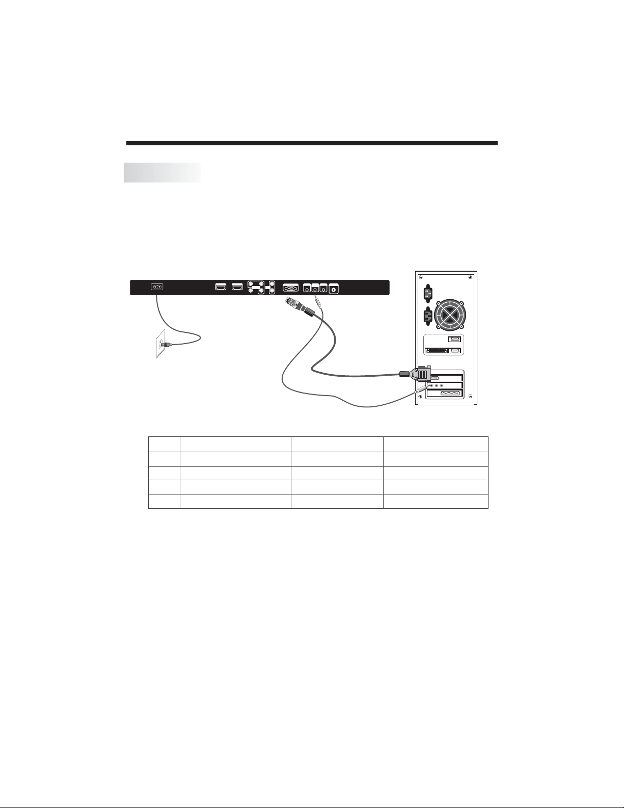
PC
STEPS:
Be sure both the TV and computer are powered off.
1. Connect a VGA and audio cable.
2. Connect the power cord.
3. switch to VGAmode.
Turn on the TV and
4.
Turn on the PC.
HDMI2
ACINPUT
100-240V~50/60Hz
PRESET MODE
HDMI1
Pb
L
Pr
AUDIO
COMPONENT
INPUT
INPUT
R
Y
AV1
HEADPHONE
PCAUDIO
VGAINPUT
INPUT
INSTALLATION
RF INP UT
COAXIAL
RESOLUTION
1
2
3
4
640*480
800*600
1024*768
1280*1024
V.Freq.(Hz) H.Freq.(KHz)
60
60
60
60
31.47
37.88
48.36
63.98
-7-
Page 9

ANTENNA
INSTALLATION
Note:
Aerial connections:IEC(female).
Input impendance:75 unbalanced.
-8-
Page 10

INSTALLATION
AV EQUIPMENT
There are two HDMI ports located on the back of your TV. You can connect a Blu-ray player, DVD player, or
other video equipment through these ports.
There is one component (Y, Pb, Pr) and two composite (AV) video input located on the back of your TV. You
can connect a VCR, cable box, or other video equipment to these jacks.
Please see the diagram below. You may also need to refer to the owner's manual of the device that you are
trying to connect.
VIDEO EQUIPMENT with YPbPr
G
R
Y
Yellow(video)
W
White(audio L)
R
Red(audio R or Pr)
B
Blue(Pb)
G
Green(Y)
ACINPUT
100-240V~50/60Hz
B
W
R
G
R
B
HDMI2
HDMI1
Pr
COMPONENT
INPUT
AV1
Pb
AUDIO
INPUT
Y
W R
R
W
HEADPHONE
VGAINPUT
L
R
PCAUDIO
RF I NPUT
COAXIAL
INPUT
HDMI
VIDEO EQUIPMENT
W R
To audio outputs
The television's inputs can be connected to the following types of equipment: VCR, multi disc player, DVD,
camcorder, video game or stereo system, etc.....
There is a composite (AV) video input and a USB port located on the side of the TV. You can use this AV
input to conveniently connect devices that you may frequently connect and disconnect, such as a camcorder.
TO VIDEO
output
R
L
AV2
Video
USB
-9-
Page 11

The remote control cannot be operated unless the batteries are properly loaded.
When using the remote control, aim it at the remote control sensor on the TV.
Function introduction
1.Press to turn on and off the TV.
2.Press repeatedly to cycle through the available
picture modes.
3.Press to change the aspect ratio.
4.Select a closed caption option.
5.Show the input source.
6.Press to open the on-screen menu.
Press CH+ or CH- to go to the next or previous
7.
channel in the
channel list.
Press VOL+ or VOL- to increase or decrease the volume.
8.Exit On Screen Display.
9.USB function
Fast / Backward / Forward (The buttons do not
work.) Stop Play / Pause REPEAT.
10.Press to display the TV status information on the top
of the TV
screen.
11.Shows program schedule in TV.
12.Press to cycle through different sound settings.
13.Press to display the sleep timer option.
14.Select MONO, STEREO, SAP in NTSC system.
15.Press to change a channel.
16.Press to select digital channels. For example, to
enter “54-3”,
press “54”, “- ” and “3”.
17.Switches the TV sound on or off.
Press to confirm selections in an on-screen menu or
18.
to open
a submenu.
19.Press to go to the last viewed channel.
20.Open the channel list in TV.
21.Open the favorite channel list in TV.
.Comtrol the System. / Rewind /
REMOTE CONTROL
-10-
Page 12
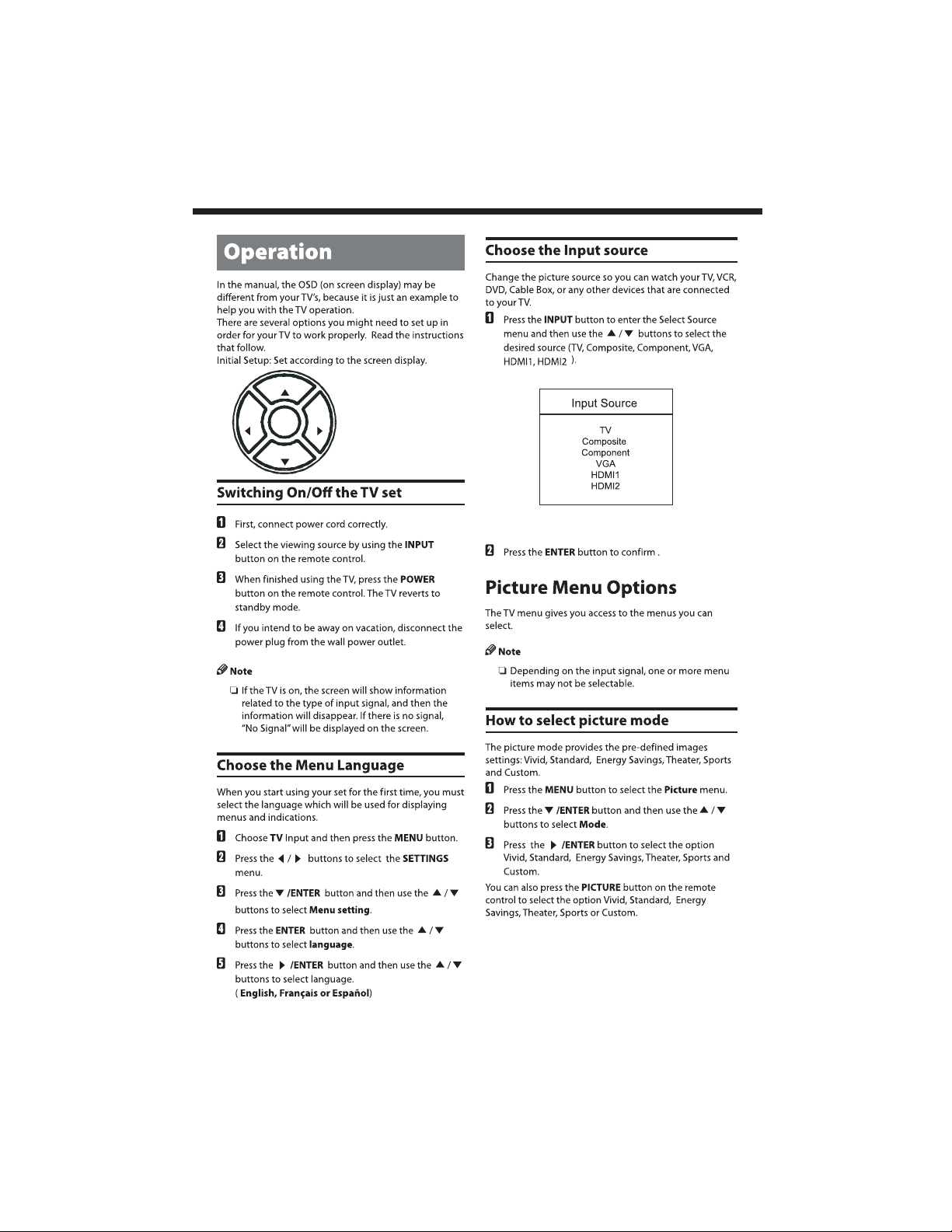
CH+
OPERATION
VOL+
VOL-ENTER
CH-
-11-
Page 13
OPERATION
-12-
Page 14

OPERATION
-13-
Page 15

OPERATION
-14-
Page 16
OPERATION
-15-
Page 17
OPERATION
-16-
Page 18

OPERATION
-17-
Page 19

OPERATION
-18-
Page 20

OPERATION
-19-
Page 21

OPERATION
-20-
Page 22

OPERATION
-21-
Page 23

REPEAT
OPERATION
-22-
Page 24

TROUBLE SHOOTING
Trouble phenomenon Symptom
Picture Audio
Snow Noise
Ghost
Interference
Normal Picture
No picture Mute
No color Normal audio Color control
Normal audio
Noise
Mute
Inspection Check
antenna position, direction
or connection
antenna position, direction
or connection
electronic equipment,car/
motorcycle,fluorescent light
Volume (check if mute is
activated or if the audio system
connections are not correct)
Power cord is not inserted
Power switch is not opened
Contrast and brightness/volume
setup
Press standby key on the remote
control for inspecting
Picture
breaking up
No color
Normal audio
or weak
Noise
Retune channel
TV system
The LCD TV panel is built with very high precision technology giving you fine picture details
in vibrant color. Occasionally, a few non-active pixels may appear on the screen as a fixed
point of red, green, blue, black or white. Please note this does not affect the performance of
the product.
-23-
Page 25

WARRANTY
-24-
Page 26

 Loading...