

Haier L32B1120a User Manual

L32B1120

-1-
Contents
Safety and warnings.......................................................................................2-3
Introduction..................................................................................................4
Installation...................................................................................................5-8
Remote Control............................................................................................9
Operation.....................................................................................................10-14
Trouble Shooting..........................................................................................15
Warranty......................................................................................................16

-2-
SAFETY AND WARNINGS
IMPORTANT SAFETY INSTRUCTION
TO REDUCE THE RISK OF ELECTRIC SHOCK, DO
NOT REMOVE COVER (OR BACK).NO USER
SERVICEABLE PARTS INSIDE. REFER SERVICING
TO QUALIFIED SERVICE PERSONNEL.
RISK OF ELECTRIC SHOCK
DO NOT OPEN!
CAUTION
CAUTION
The symbol indicates that dangerous
voltages constituting a risk of electric shock
are present within this unit.
The symbol indicates that there are
important operating and maintenance
instructions in the literaturaccompanying this
unit.
To reduce the risk of fire or electric shock, do
not expose this apparatus to rain or moisture.
WARNING:
1) Read these instructions.
2) Keep these instructions.
3) Heed all warnings.
4) Follow all instructions.
5) Do not use this apparatus near water.
6) Clean only with dry cloth.
7) Do not block any ventilation openings, install in
accordance with the instructions.
8) Do not install near any heat sources such as
radiations, heat registers, stoves, or other apparatus
(including amplifiers) that produce heat.
9) Do not defeat the safety purpose of the polarized
plug. If the provided plug does not fit into your
outlet, consult an electrician for replacement of the
obsolete outlet.
10) Protected the power cord from being walked on
or pinched particularly at plugs, convenience
receptacles, and the point where they exit from the
apparatus.
11) Only use attachments/accessories specified by
the manufacturer.
12) Unplug this apparatus during lighting storms or
when unused for long periods of time.
13) Refer all servicing to qualified service
personnel. Servicing is required when the
apparatus has been damaged in any way, such as
power-supply cord or plug is damaged, liquid has
been spilled or objects have fallen into the
apparatus, the apparatus has been exposed to rain or
moisture, does not operate normally, or has been
dropped.
14) Mains plug is used as the disconnect device, the
disconnect device shall remain readily operable.
15) The ventilation should not be impeded by
covering the ventilation openings with items, such
as newspapers, table-cloth, curtains, etc.
16) No naked flame sources, such as lighted
candles, should be placed on the apparatus.
17) Attention should be drawn to the environmental
aspects of battery disposal.
18) The use of apparatus in moderate climate.
19) The apparatus shall not be exposed to dripping
or splashing and that no objects filled with liquids,
such as vases, shall be placed on the apparatus.
This symbol indicates that this product
incorporates double insulation between
hazardous mains voltage and user accessible
parts. When servicing use only
identical replacement parts.
This marking indicates that this product should
not be disposed with other household wastes
throughout the EU. To prevent possible harm to
the environment or human health from
uncontrolled waste disposal, recycle it
responsibly to promote the sustainable reuse of
material resources. To return your used device,
please use the return and collection systems or
contact the retailer where the product was
purchased. They can take this product for
environmental safe recycling.
The batteries shall not be exposed to
excessive heat such as sunshine, fire or the
like.
WARNING:
The excessive sound pressure from earphones
and headphones can cause hearing loss.
WARNING:
Haier is committed to safely recycling
electronic products and product materials.
Please check for a local recycling location in
the United States at: 1800RECYCLING.COM
or call 1.800.RECYCLING.
-3-
High voltages are used in the operation of this television
receiver. Do not the cabinet.
Refer servicing to qualified service personnel.
open
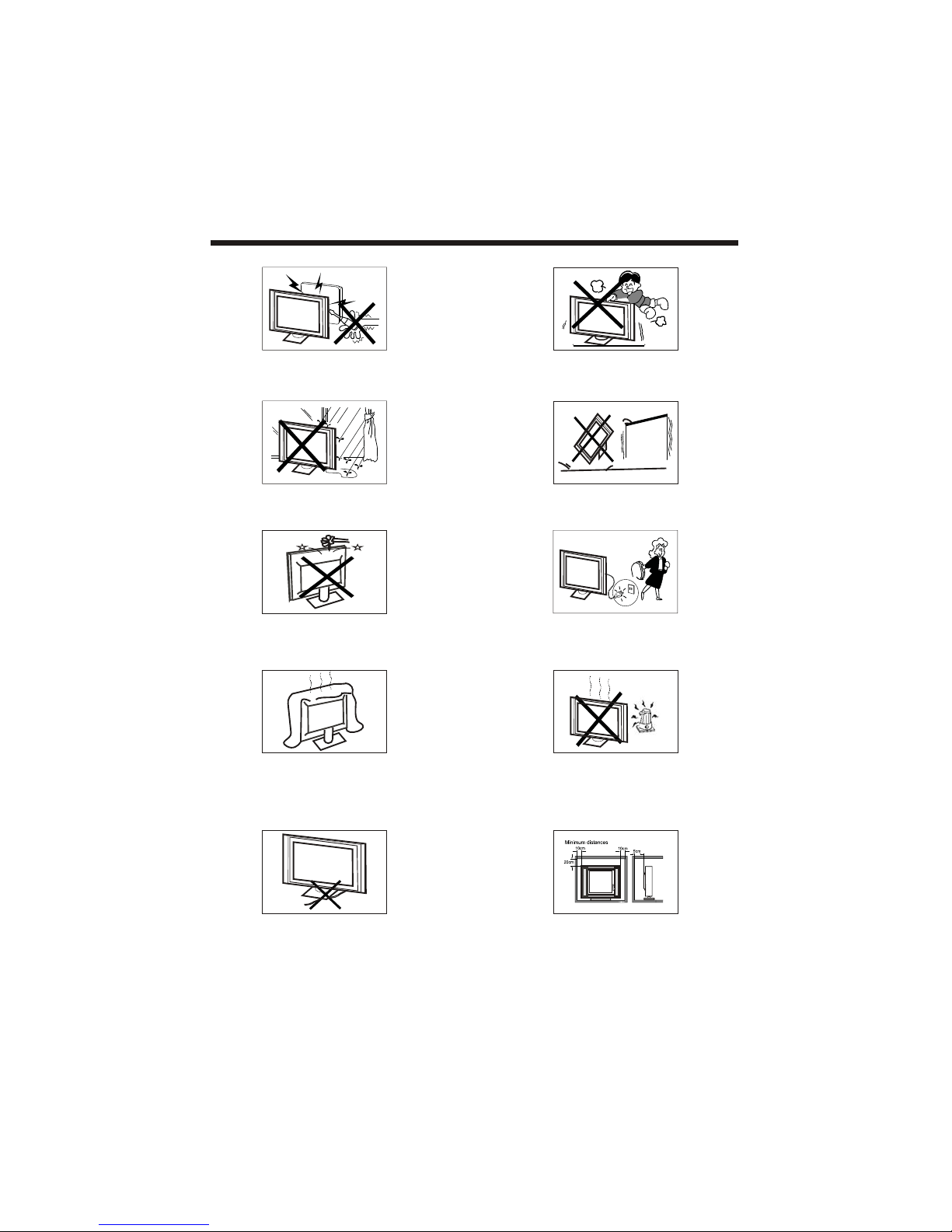
SAFETY AND WARNINGS
To prevent fire or electrical shock hazard, do not expose
the television receiver to rain or moisture.
Do not drop or push objects into the television cabinet
slots or openings. Never spill any kind of liquid on the
television receiver.
Do not block the ventilation holes on the back cover .
Adequate ventilation is essential to prevent failure of
electrical components.
of the TV
Do not trap the power supply cord under the television
receiver s .' stand
Never stand on, lean on, or suddenly push the television or
its stand. You should pay special attention to children.
Serious injury may result if it falls.
Do not place your television on an unstable cart, stand,
shelf or table. Serious injury to an individual and damage
to the television may result if it falls.
/or
When the television receiver is not used for an
extended period of time, it is advisable to disconnect
the AC power cord from the AC outlet.
Avoid exposing the television receiver to direct sunlight
and other sources of heat. Do not stand the television
receiver directly on other products which give off heat,
e.g. video cassette players and audio amplifiers. Do not
place naked flame sources, such as lighted candles on
the television. or near
Dim:515*320mm(
If the television is to be built into a compartment or similar
enclosure, the minimum distances must be maintained. Heat
build-up can reduce the life of your television, and can also
be dangerous.
-4-
INTRODUCTION
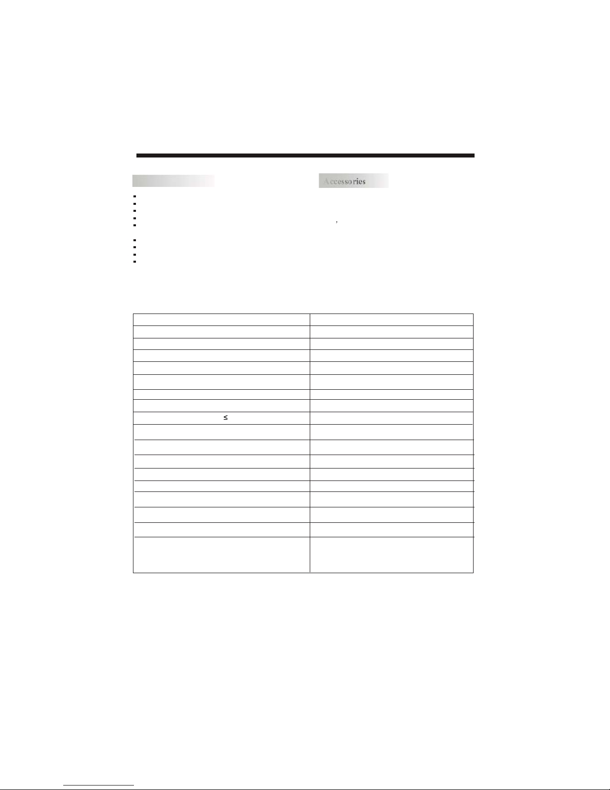
Main features
Accessories
Infrared Remote Control....................
1
User s M anual .................................
1
Battery(AAA)................................... 2
Accessories
Resolution:
Aspect Ratio:
TV System:
Video Signal System:
Receiving Channel:
Input Power Voltage:
Power consumption:
Main parameter
YCb(Pb)Cr(Pr) Input
Horizontal definition(TV line)
Viewing Picture Size(diagonal)
1366x768
16:9
135W
Audio Output Power (THD 7%): 2x8W
NTSC
Cable :1-135/ Air: 2-69 (ATV&DTV)
Analog RGB(VGA) Input x 1
High-Definition Multimedia Interface(HDMI) Input x 3
Audio Input x 3
Composite Video Input >=350
x 1
YCb(Pb)Cr(Pr) >=400
Video Input >=400
32 inches
Composite Video Input x 2
AC 100V-240V 50/60Hz
ATSC Digital system and NTSC Analog system
Headphone Output
x 1
x 1
Coaxial Output
Power Cable.....................................
1
1366 x 768 native resolution for HD performance
Integrated ATSC TV tuner for HDTV broadcast reception
High brightness provides a vivid and brilliant picture
Deeper blacks and brighter whites with high contrast
Wide Screen aspect ratio (16:9) for a complete home
theater experience
HDMI input for true digital connection
VGA port for connection to PC
Built-in stereo speaker system
Full-function Remote Control
x 1
USB Input
-5-
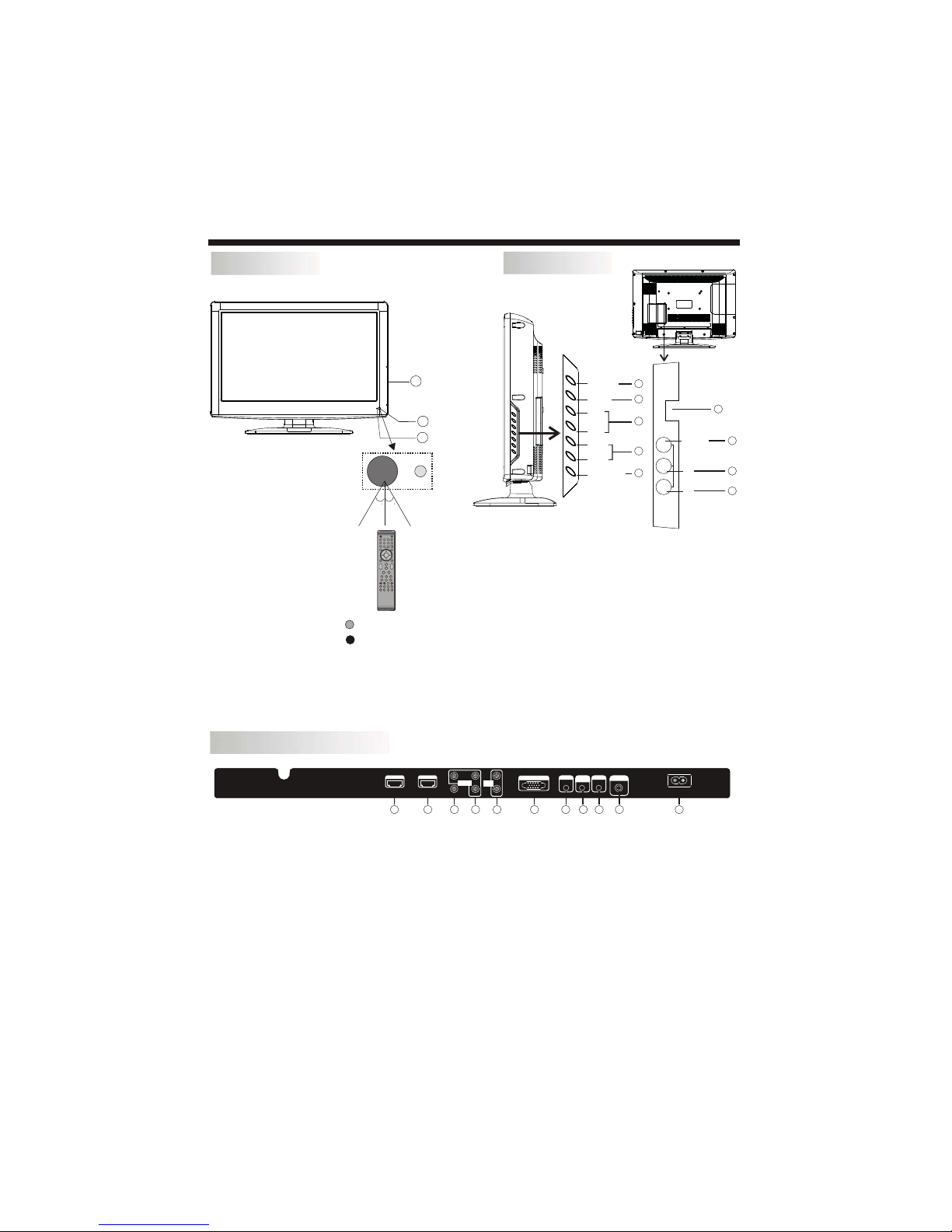
INSTALLATION
Front panel
REAR AV INPUT/OUTPUT
1: Remote control sensor.
2: Indicator LED: GREEN POWER ON.
RED STANDBY.
3: Side panel keys
1. SOURCE: Display the input source menu.
2. MENU: Display main MENU.
3. CH+/CH-: In TV mode, press "CH+" or "CH-" to
change the channel up and down. In MENU mode, press
"CH+" or "CH-" to select items in standby mode, press
"CH+" or "CH-" to turn on the TV.
4. VOL+/VOL-: Adjust sound level. In MENU mode,
press "VOL+ " or "VOL- " to adjust the item that you
selected.
5. STANDBY: Press this button to turn the unit ON
from STANDBY mode. Press it again to turn the set
back to STANDBY.
6. USB INPUT
7. VIDEO INPUT
8. AUDIO INPUT-L
9. AUDIO INPUT-R
Side panel
SOURCE
MENU
CH+
CH-
VOL+
VOL-
STANDBY
1 2 3
4 5 6
7 8 9 0
+
CH
_
+
_
VOL
30 30
3
1
2
VIDEO
L
R
AV2
USB
R
L
VIDEO
Note: 1. Composite video input and component video input share the audio input.
2. When DVI connect is used on HDMI 1 Input, use "PC Audio" for the audio signal input.
3. When a DVI connection is used on the HDMI 2 Input, use "YPbPr Audio" for the audio signal input.
a ion the
7. Headphone Output
8. PC Audio Input
9. Coaxial
10. Antenna Socket
11. AC Power Socket
1. HDMI1 Input
2. HDMI2 Input
3. Composite Video Input
4. Component Video (YPbPr) Input
5. Audio Input
6. VGA Port (PC Input)
HDMI1 INPUT HDMI2 INPUT
AC INPUT
100-240V~50/60Hz
L
R
AV1PrY
Pb
HEADPHONE
PC AUDIO
INPUT
COAXIAL
RF INPUT
AUDIO
INPUT
VGA INPUT
Component
input
1 2
3
4 5
6 7 8
9
10 11
1
2
3
4
5
6
7
8
9
 Loading...