

Page 1
L26/32/37V6-A8KK
Page 2

1. Features
2. Safety Precautions
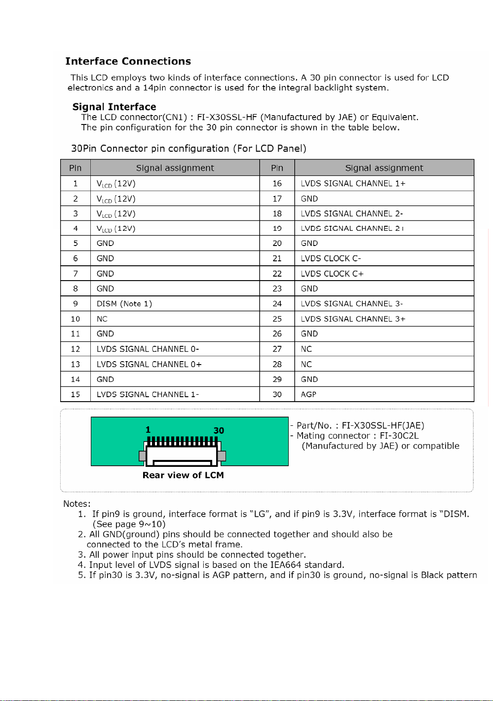
3. Panel Part
4. Bus Control Adjustment
5. Circuit Diagram
6. User's manual
Page 3
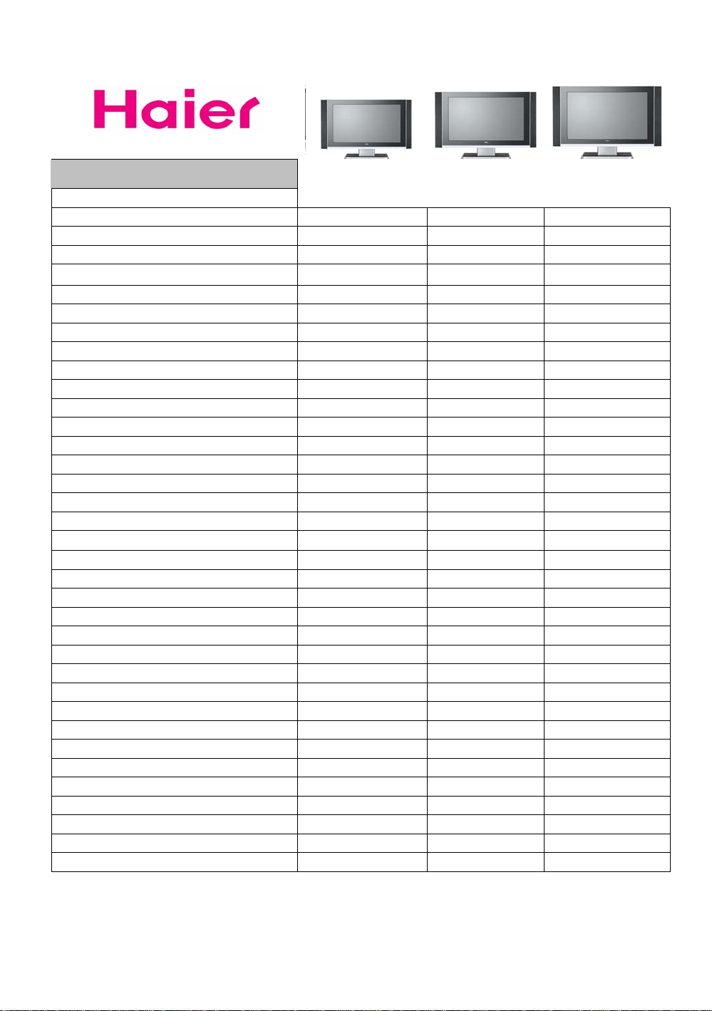
1. Features
Functions
Aspect Ratio 16:9 16:9 16:9
Screen size (inches) 26" 32" 37"
Resolution 1366*768 1366*768 1366*768
Brightness 500 cd/m2 500 cd/m2 500 cd/m2
Contrast 600:1 800:1 800:1
Response time(ms) 8ms 8ms 8ms
Viewable Angle H:176°, V:176° H:176°, V:176° H:176°, V:176°
Surpported Colors 16.7M Colors 16.7M Colors 16.7M Colors
Color system PAL/SECAM PAL/SECAM PAL/SECAM
Sound system DK/BG/I/L/L' DK/BG/I/L/L' DK/BG/I/L/L'
Digital comb filter yes yes yes
Multiple Picture Modes yes yes yes
Color temperature control yes yes yes
AV Stereo yes yes yes
MTS/SAP/NICAM yes yes yes
Multiple Sound modes yes yes yes
AVL(Auto-Volume leveler) yes yes yes
Built-in speakers output(W) 5W*2 5W*2 5W*2
Trilingual OSD yes yes yes
ATS yes yes yes
OSD Language Multi-language Multi-language Multi-language
Auto channel setup yes yes yes
RF input 1 1 1
Composite input 1 1 1
SCART input 2 2 2
15 Pin D-sub(VGA) 1 1 1
HDMI input 1 1 1
Component input 1 1 1
User's manual yes yes yes
Remote control yes yes yes
Stand yes yes yes
Wall-mount optional optional optional
Working power consumption(W) 150W 150W 220W
Stand-by power consumption(W) 3W 3W 3W
Voltage Range(V) 150~240V 150~240V 150~240V
L26V6-A8K L32V6-A8K L37V6-A8K
Page 4
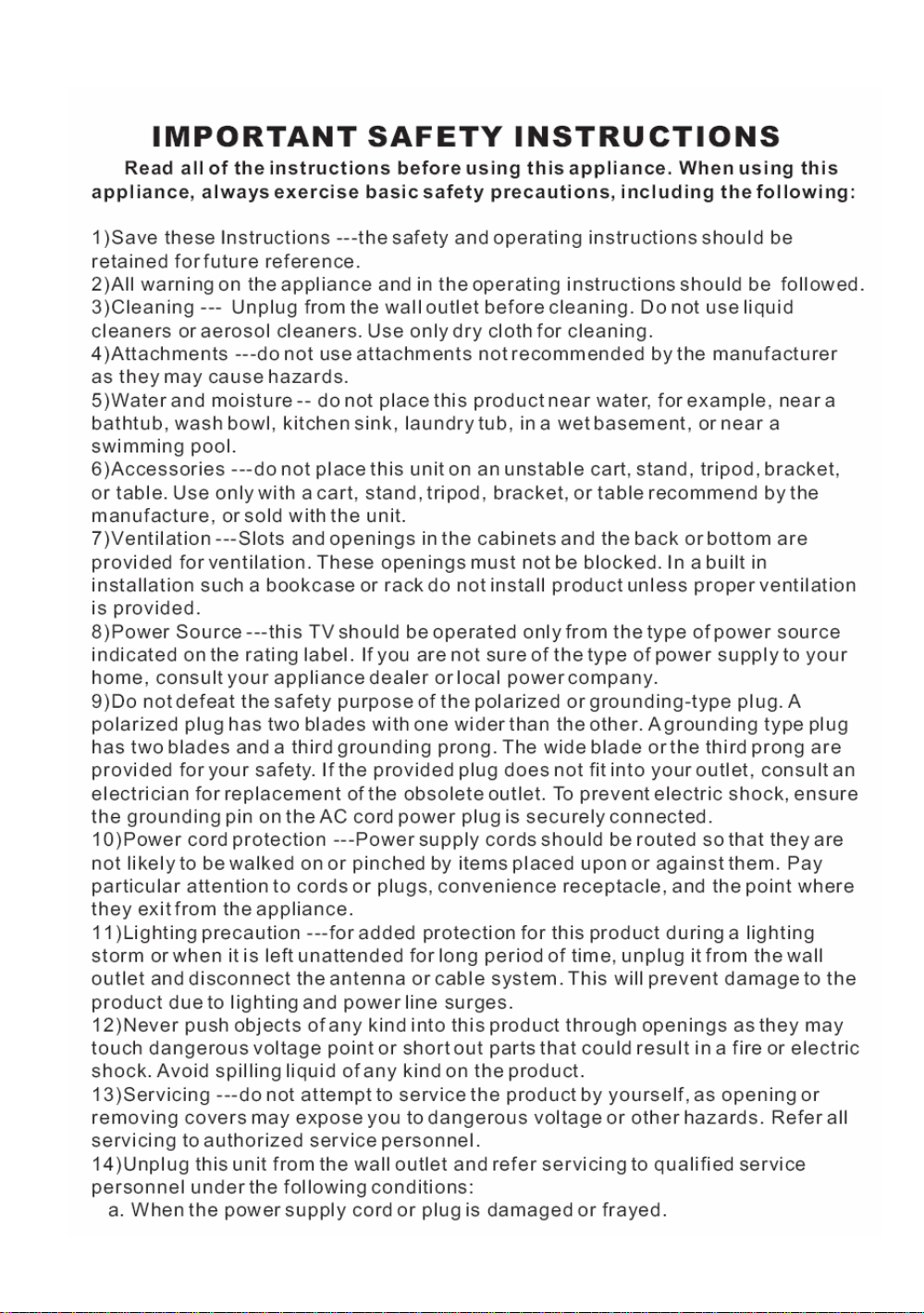
2. Safety Precautions
Page 5
Page 6
Page 7
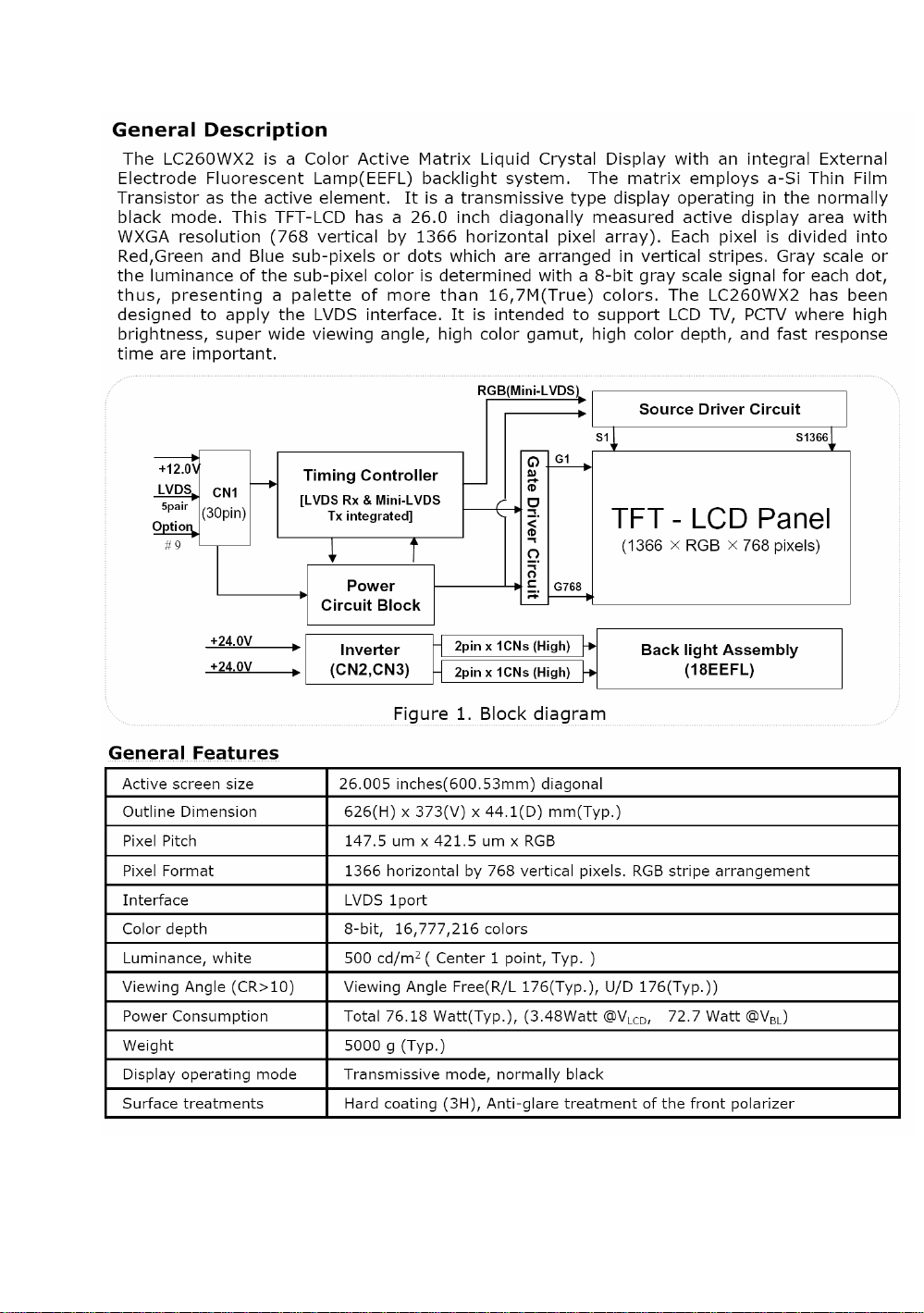
3. Panel Part
3-1 L26V6-A8K
Page 8
Page 9

Page 10

3-2 L32V6-A8K
Page 11

Page 12

Page 13

3-3 L37V6-A8K
Page 14

Page 15

Page 16

4. Bus Control Adjustment
Page 17

Page 18

Page 19

Page 20

Page 21

5.Circuit Diagram
Page 22

Introduction to Circuit Boards
A: MAIN CHIP SUMMARY
U11 M30620: 16-BIT CMOS SINGLE-CHIP MICROCOMPUTER
The single-chip microcomputer operate using sophisticated instructions featuring a high
level of instruction efficiency. With 1M bytes of address space, they are capable of executing
instructions at high speed. In addition, this microcomputer contains a multiplier and DMAC which
combined with fast instruction processing capability.
U1 SVP-EX52: VIDEO DECODER+DE-INTERLACE+SCALE
The SVP_EX-52 video processor is a highly integrated system on a chip device, targeting
the converging HDTV-ready and PC-ready and LCD TV, PDP TV, and DLP TV applications
where high precision processing of video and data are the requirements. SVP_EX-52 contains
dual-purposed triple 10-bit high-precision and high-speed video ADCs for both PC and video
inputs, a high performance 5th generation multi-format 3D digital comb video decoder that
supports NTSC, PAL and SECAM, an HDTV sync separator, motion adaptive de-interlacing
engine, and the video format conversion engine,
U4 MST3788: 8-bit Analog and HDCP Interface for Advanced Digital Displays
The MST3788 integrates both analog interfaces and HDCP compliant receivers for enabling
advanced digital display devices such as digital TVs, plasma displays, LCD TVs and projectors to
receive and display. Compliant with the HDCP 1.0 specification, the MST3788 enables consumer
electronic devices to receive uncompressed, high quality, digital video HD content over a single,
low-cost DVI cable.
UA11 MSP3450G: AUDIO DECODER
The MSP 34x0G family of single-chip Multistandard Sound Processors covers the sound
processing of all analog TV-Standards worldwide,
U3 K4D263238F: 128M DDR SDRAM
UA4 TPA3004: The TPA3004D2 is a 12-W (per channel) efficient,Class-D audio amplifier
fordrivingbridged-tied stereospeakers. The TPA3004D2 can drive stereo speakers as low as 4 Ω.
The high efficiency of the TPA3004
eliminates the need for external heatsinks when playingmusic.Stereo speaker volume is
controlled with a dc voltage applied to the volume control terminal offering a rangeof gain
from ¨C40 dB to 36 dB. Line outputs, for driving external headphone amplifier inputs, are also dc
voltage controlled with a range of gain from ¨C56 dB to 20 dB. An integrated 5-V regulated supply
is provided for powering an external headphone amplifier.
UA5 74HC4052 : The 74HC4052 is high-speed Si-gate CMOS devices and are pin
compatible with the HEF4052B. They are specified in compliance with JEDEC standard no. 7A.
The 74HC4052 is dual 4-channel analog multiplexers or demultiplexers with common select logic.
Each multiplexer has four independentinputs/outputs (pins nY0 to nY3) and a common
input/output (pin nZ). The common channel select logics include two digital select inputs (pins S0
Page 23

and S1) and an active LOW enable input (pin E). When pin E = LOW, oneof the four switches is
selected (low-impedance ON-state)with pins S0 and S1. When pin E = HIGH, all switches arein
the high-impedance OFF-state, independent of pins S0 and S1.
B: Debug flow-chart
AC ON
Power board: NO
STANDBY +5V FOUND
Initialization:
*Vs on
+60 +190 FOUND
GOOD
System Reset
Power On
YES
Power failure
+9V +12V +5V
+2.5V +3.3V +1.8V
FOUND
SvpEx Reset
Svpex E0 Good
InitAppHas Accomplish
Non integrity
PICTURE DISPLAY
SvpEx E0 error
Whether alternating current
input
*Repair power board.
*Replace fuse.
*Check dc-dc circuit
and LDO circuit.
*SvpEx no ack.
* SvpEx communicate with
MCU was wrong.
*SvpEx communicate with
DDR was wrong.
Page 24

6. User's manual
 Loading...