

Haier Room Air Conditioner, HSU09VHJ(DB)-W, HSU12VHJ(DB)-W, HSU18VHJ(DB)-W, HSU24VHJ(DB)-W Installation Manual
...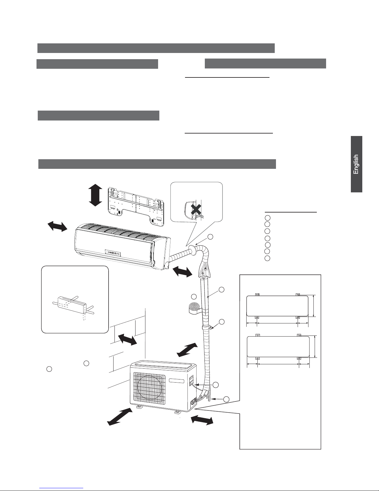
Drawing for the installation of indoor and outdoor units
Necessary Tools for Installation
Hammerƽ
Torque wrench
ƽ
(17mm ,22m m,26m m)
Nipperƽ
Reamerƽ
Hacksawƽ Pipe cutterƽ
Gas leakage detector orƽ
soap-and-water solution
Hole core drillƽ Flaring toolƽ
Spanner(17,19 and 26mm)ƽ Knifeƽ
Measuring tapeƽ
ƽ
ƽ
ƽ
ƽ
ƽ
Place where the distance of more than lm from televisions, radios, wireless apparatuses
and fluorescent lamps can be left.
ƽ
In the case of fixing the remote controller on a wall, place where the indoor unit can
receive signals when the fluorescent
ƽ
lamps in the room are in use.
ƽ
ƽ
ƽ
A distance marked
ƽ
Q
is available as illustrated in the below figure.
Before inserting power plug into receptacle, check the voltage without fail.
The power
sourceisthesameasthe
ƽ
corresponding name plate.
Install an exclusive branch circuit of the power.
ƽ
A receptacle shall be set up in a distance where the power cable can be
reached.
Donotextendthecablebycuttingit.
ƽ
Selection of Installation Place
Power Source
Preparation
NO.0010536242
Installation Manual of Room Air Conditioner
F
A
C
E
D
Optional parts for piping
Non-adhesive tape
Adhesive tape
Saddle (L.S) with screws
Connecting electric cable
forindoorandoutdoor
Drain hose
Heating insulating material
Piping hole cover
Floor fixing dimensions of the
outdoor unit
Fixing of outdoor unit
Fix the unit to concrete or blockƽ
with bolts (10mm) and nuts firmly
and horizontally.
When fitting the unit to wall
ƽ
surface, roof or rooftop, fix
a supporter securely with nails
orwiresinconsideration of
earthquake and strong wind.
If vibration may affect the
ƽ
house, fix the unit by attaching a
vibration-proof mat.
The marks from to
in the figure are the
parts numbers.
Thedistancebetween
theindoorunitandthe
floor should be more
than 2m.
ThemodelsadoptHCFCfreeref
rigerant R410A
more than
10cm (3 7/8)
more than 10cm
(3 7/8)
more than 10cm
(3 7/8)
more than 20cm
(7 7/8)
more than 15cm
(5 7/8)
more than 25cm
(9 7/8)
more than 60cm
(23 5/8)
A
G
ƽ
ƽ
A
F
C
E
D
G
B
Arrangement of piping
directions
Rear left
Left
Rear
right
Right
Below
G
Attention must be paid to
the pitch of drain hose
The above picture is for your reference only. Your product may look different.
Read this manual before installation.
Explain the operation of the unit to the user according to this manual.
Indoor Unit - Select a location that is
Outdoor Unit - Select a location that is
Robust not causing vibration, where the body can be supported sufficiently.
Not affected by heat or steam generated in the vicinity, where inlet and outlet of the
unit are not disturbed.
Possible to drain easily, where piping can be connected with the outdoor unit.
Where cold air can be spread in a room evenly.
Nearby a power receptacle. (Refer to drawings).
Less affected by rain or direct sunlight and is sufficiently ventilated.
Strong enough to bear the unit, where vibration and noise are not increased.
(4 1/2)
For:24k
Not causing a nuisance to neighbors due to discharged air or noise.
(10 1/16)
(5 1/2)
(19 2/3)
(5 1/2)
(24 7/8)
(4 1/2)
(13 1/2)
140 500
140
256
113.5
113.5
633
340
For:09k 12k 18k
(Unit:mm / inch)
Indoor unit
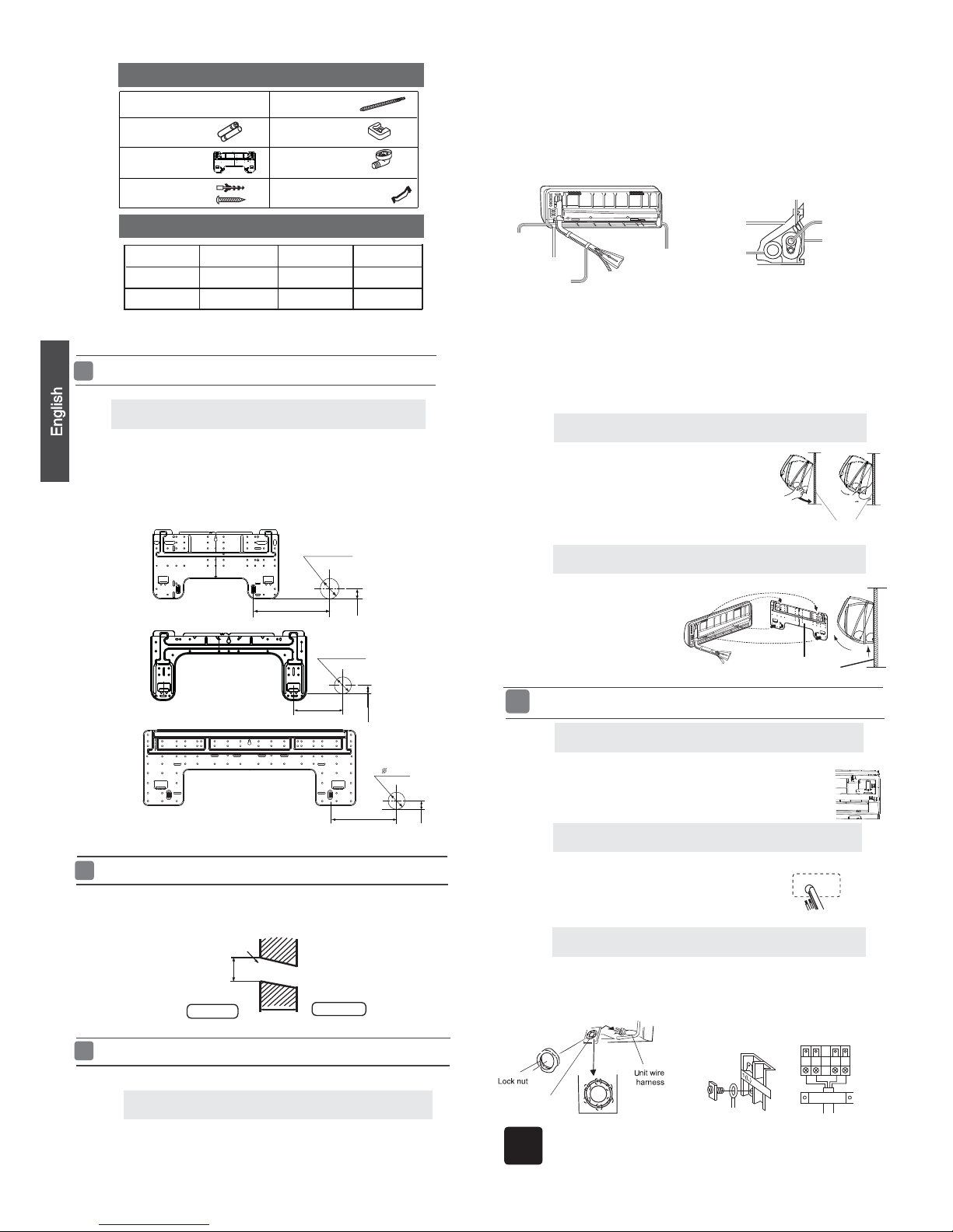
Make a hole of 70 mm (2 3/4) in diameter, slightly descending to outside the wall.
ƽ
Install piping hole cover and seal it off with putty after installation
ƽ
Whenthemountingplateisfirstfixed
1. Carry out, based on the wall studs or lintels, a
to be fixed against the wall, then temporarily fasten the plate with one steel nail.
2. Make sure once more the proper level of the plate, by
hanging a thread with a
weight from the central top of the plate, then fasten the plate.
3. Find the wall hole location A using a measuring tape
FittingoftheMountingPlateand
PositioningofthewallHole
Lid for right
piping
Lid for under piping pipe
Fix with adhesive tape
Lid for left piping
Indoor/outdoor electric cable and drain hose must be bound with refrigerant
ƽ
[ Other piping direction ]
Cut away, with a nipper, the lid for piping according to the piping direction and
ƽ
then bend the pipe according to the position of wall hole. When bending, be
careful not to crush
pipes.
Connect beforehand the indoor/outdoor electric cable,
ƽ
andthenpulloutthe
connected to the heat insulation of connecting part specially.
proper leveling for the plate
Making a Hole on the Wall and Fitting the Piping Hole Cover
Drawingofpipe
Installation of the Indoor Unit
[Rearpiping ]
Drawpipesandthedrainhose,thenfastenthemwiththeadhesivetape
ƽ
[Left·Left-rear piping ]
In case of left side piping, cut away, with a nipper, the lid for left piping.
ƽ
In case of left-rear piping, bend the pipes according to the piping direction to
ƽ
the mark of hole for left-rear piping which is marked on heat insulation materials.
1. Insert the drain hose into the carity of heat insulation materials of indoor unit.
2. Insert the indoor/outdoor electric cable from backside of indoor
unit, and pull it
o
ut on the front side, then connect them.
3.Coattheflaringsealfacewithrefrigerantoilandconnect pipes.
Fixing the indoor unit body
ƽ
Inordertofixthebodyontothemountingplate,holdup
ƽ
the body at a slant from the underside and then put it down
perpendicularly.
Connecting the indoor/outdoor Electric Cable
Removing the wiring cover
Remove terminal cover at right bottom corner of indoor unit, then takeƽ
off wiring cover by removing its screws.
1. Insert from outside the room cable into left side of the wall
hole,inwhichthepipehasalreadyexisted.
2. Pull out the cable on the front side, and connect the cable
making a loop.
Note
When connecting the cable, confirm the terminal number of indoor and
outdoor units carefully. If wiring is not correct, improper operation may
ƽ
ƽ
ƽ
mounting plate
When connecting the cable after installing the indoor unit
When connecting the cable before installing the indoor unit
When you unload the indoor unit, please use
bottom of the body outward slightly
and lift the unit until it leaves the
mounting plate.
mounting plate
Unloading of indoor unit body
ƽ
your hand to raise the body, then lift the
Remote controller (1)
AAA dry battery (2)
Mounting plate (1)
Drain hose (1)
Ø4X25 Screw
(4)
Plastic cap (4)
Drain-elbow (1)
Cushion (4)
Pipe supporting plate (1)
Accessory parts
NOTE˖The thickness of the pipe must be 0.8mm(1/16”) at least.
Selectionofpipe
2
Insert the cord from the back side of the unit, then pull it out on the front side.
Fasten the unit wire harness to the conduit holder using the lock nut.
Position the conduit holder to its original state using screw.
Conduit holder
Cut the 6 slit sear
Cover the connection part with heat insulation materials, cover with adhesive tape.
piping with protecting tape.
Hang the unit body securely onto the upper notches of the
mounting plate. Move the body from side to side to verify
its secure fixing.
Indoor side
Outdoor side
Ø70mm
Wall hole
Thickness of wall
Heat insulation
material
Drain hose
Piping
Pipe supporting
plate
Indoor/outdoor electric cable
Liquid pipe (Ø)
6.35mm(1/4”)
Gaspipe(Ø)
9.52mm(3/8”)
A=145mm
35mm
B=
70mm
Ø
For 09K 12K
For 18K
6.35mm(1/4”)
12.7mm
(1/2”)
A=150mm
B= 70mm
35mm
Type
For 24K
9.52mm(3/8”)
15.88mm
(5/8”)
A=145mm
B=
70mm
Ø
30mm
occur and cause damage to the units.
(2 3/4)
(5 5/7)
(1 3/8)
(2 3/4)
(1 1/6)
(5 5/7)
(2 3/4)
(5 7/8)
(1 3/8)
(2 3/4)
Pitch downward for drainage
2.Thewiringmethodshouldbeinlinewiththelocalwiringstandard.
3. After installation, the power plug should be easily reached.
4. A breakershouldbeincorporatedintofixedwiring.Thebreakershouldbe
all-pole
switch.
Outdoor unit
Install according to Drawing for the installation of indoor and
outdoor units
ƽ
and the bending radius should be 30 (1 1/6) to 40
mm (1 4/7) or longer.
Connecting the pipe of gas side first makes working easier.
ƽ
TheconnectionpipeisspecializedforR410A.ƽ
Installation of Outdoor Unit
Half union
Flare nut
Tor que w ren ch
The standard pipe length is 7m (27 9/16) . If it is over 7m (27 9/16) , the function
oftheunitwillbe
affected.Ifthepipehas tobelengthened,therefrigerantshould
be charged,
accordin
g to 20 g/m (0.018 oz/inch)
.Butthec
harge of refrigerant must
be conducted by professional air conditioner servicer. Before adding additional
refrigerant, perform air
purging from the refrigerant pipes and indoor unit using
a v
acuum
pump,then
Spanner
Forced fastening without careful centering may
damage the threads and cause a leakage of gas.
Pipe Diameter(ǿ) Fastening torque
Liquid side6.35mm(1/4") 18N.m/13.3Ft.lbs
Liquid/Gas side9.52mm(3/8") 42 N.m/30.1Ft.lbs
Gas side 12.7mm(1/2") 55N.m/40.6Ft.lbs
Gas side 15.88mm(5/8") 60 N.m/44.3Ft.lbs
Connection of pipes
charge additional refrigerant.
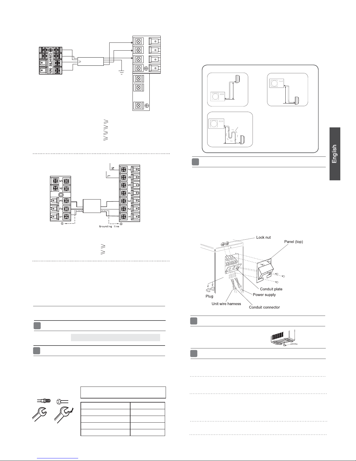
Outdoor unit
Indoor unit
A
B
Outdoor unit
Indoor unit
A
B
A
B
Outdoor unit
Indoor unit
Oil trap
CAUTION
Max.Elevation: Amax=1m
●
In case the elevation A is more●
than 5m, oil trap shoud be
installed every 5~7m
Max. Length: Bmax=15m
●
Incasethepipelength B is●
more than 10m, the refrigerant
should be charged, according
to 20 g/m.
3
Connection
If the drain-elbow is used,ƽ
please attach it as figure. (Note:
Onlyforheatpumpunit.)
1.
Open the handle on low side of manifold and
2.
operate vacuum pump. If the low
3.
After the
completion of vacuuming, close the
handle ‘Lo’ in gaugemanifold and
stop the operation of the vacuum pump.
Attaching Drain-Elbow
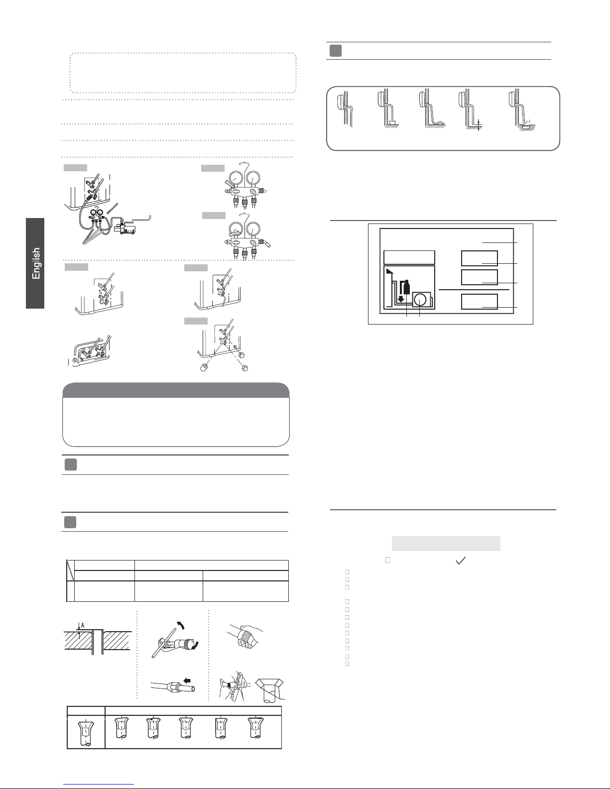
PurgingMethod:Tousevacuumpump
Open the valve rod stem the 2-way valve counterclockwise to 90 degrees.4.
After 6 seconds, close the
2-way valve and inspect for
gas leakage.
Power cable:
HSU12VHJ(DB)-W
Outdoor unit
3
2
^
Power
Wiring
1
)
(
N
)
(L
)
(
C
3
2
1
)
(
N
)
(
L
)
(
C
Indoor unit
Power cable:
ƽ
ƽ
ƽ
ƽ
ƽ
ƽ
Take off the panel(top), by removing the 5 screws.
Remove the plugs on the conduit plate.
Temporarily mount the conduit tubes on the conduit plate.
Connect both the power supply and unit wire harness to
the corresponding terminals on the terminal board.
Ground the unit in accordance with local codes.
Allow several extra inches of wire for making wiring
connections.
Use lock nuts to secure conduit tubes.
ƽ
To bend a pipe, be careful not to crush the pipe,
HSU09VHJ(DB)-W
HSU24VHJ(DB)-W
HSU18VHJ(DB)-W
HSU12XCK-W
HSU09XCK-W
Power cable:
Power cable:
Power cable:
Power cable:
1. If the fuse on PC board is broken please change it with the
type of
T. 3.15A/250V(indoor unit),25A/250V(outdoor unit).
4wire 18AWG
2wire with ground 16AWG
2wire with ground 16AWG
2wire with ground 12AWG
2wire with ground 12AWG
2wire with ground 16AWG
2wire with ground 16AWG
Outdoor unit
Indoor unit
Remove the service port cap of the 3-way valve and the valve stem cap for both
valves. Connect the low pressure hose from the manifold set to the 3-way valve.
Connect the center hose to the vacuum pump.
side gauge reaches a vacuum immediately, ensure the hoses are connected
properly and the low side manifold handle is open.
Vacuum for a minimum of 15 minutes and check the gauge for a proper vacuum.
Leave the hoses connected and check
the vacuum level again in 1-2 minutes. If you lose the vacuum, ensure all
connections are tight and flare the tubes again if needed.
Ensure that no dirt or debris enters the pipe.
Control Wiring
All models: Control cable: 4wire, 18AWG
Open
No gas leakage?5.
Detach the charge hose6.
from the service port, open 2-way valve and 3-way. Turn
In case of gas leakage, tighten parts of pipe connection. If
leakage stops,
then proceed
Anti countercurrent joint
Gaugemanifold(for
R410A)
2-way valve Liquid Side
3-wayvalveGasSide
Vacuum pump (for R410A)
Tube(for R410A)
Close
2-way valve
3-way valve
Open 90
O
2-way valve
3-way valve
2-way valve
3-way valve
2-way valve
3-way valve
Valve rod cap
Valve rod cap
Service port cap
To prevent the gas
leakage,
After attaching each cap, check for gas leakage around the caps.
7
.
8.
Step 1.
Step 2.
Step 3.
Step 7.
Step 6.
Step 4.
The power source must be exclusively used for air
ƽ
conditioner. (Over I0A)
In the case of installing an air conditioner in a moist place,
ƽ
please install an ea-
For installation in other places, use a circuit breaker as far
ƽ
as possible.
Pipecuttingiscarriedoutwith a pipecutterandbursmust
ƽ
be removed.
After inserting the flare nut, flaring work is carried out.
ƽ
Iftherefrigerant of theairconditionerleaks,itisnecessarytodischargeallthe
ƽ
refrigerant. Vacuum first, then
charge the liquid re
frigerant into air conditioner
accordingtotheamountmarkedonthenameplate.
Please do not let other cooling medium, except specified one (R410A), or air
ƽ
enter into the cooling circulation system. Otherwise, there will be abnormal
high pressure in the system casuing damage and possibly personal injuries.
Power Source Installation
CuttingandFlaringWorkofPiping
Flare tooling die
1.Cut pipe
2.Remove burs
3.Inserttheflarenut
CAUTION
FlaretoolforR410A Conventionalflaretool
Clutch-type clutch-type(Rigid-type) Wing-nut type (Imperial-type)
A
0~0.5mm
1.0~1.5mm
1.5~2.0mm
rth leakage breaker (GFCI).
4.Flare pipe
Lean
Damage of flare Crack Partial Too outside
Correct Incorrect
On Drainage
It becomes
high midway.
The gap with the
ground is too small
Thereisthebad
smell from a ditch
It waves.
The end is immersed in water.
Pleaseinstallthedrainhosesoastobedownwardslopewithoutfail.
Please don’t do the drainage as shown below.
ƽ
ƽ
Pleasepourwaterinthedrainpan of theindoorunit,and
ƽ
is carried out surely to outdoor.
In case that the attached drain hose is in a room, please
ƽ
applyheatinsulationto
Less than
5cm
confirm that drainage
it without fail.
4
CheckItemsforTestRun
Put check mark
in boxes
Gas leak from
pipeconnecting
?
Heat insulation of
Are the connecting wirings of indoor and outdoor firmly
Is the connecting wiring of indoor and outdoor firmly fixed?
Is drainage securely carried out?
Is the ground wire securely connected?
Is the indoor unit securely fixed?
Is power source voltage abided by the code?
Is there any noise?
Isthelampnormallylighting?
Are cooling and heating (when in heat pump) performed normally?
Is the operation of room temperature regulator normal?
Pleasekindlyexplaintoourcustomershowtooperate
through the instruction manual.
Check for Installation and Test Run
Ƶ
inserted to the terminal block?
Ƶ
1
1+2=
kg
R410A
2
kg
2=
1=
B
C
D
FE
kg
A
This product contains fluorinated greenhouse gases covered by
the Kyoto Protocol. Do not vent into the atmosphere.
Refrigerant type:R410A
GWP* value:1975
GWP=global warming potential
Please fill in with indelible ink,
• 1 the factory refrigerant charge of the product
• 2 the additional refrigerant amount charged in the field and
• 1+2 the total refrigerant charge
on the refrigerant charge label supplied with the product.
The filled out label must be adhered in the proximity of the product
charging port (e.g. onto the inside of the stop valve cover).
A contains fluorinated greenhouse gases covered by the Kyoto
Protocol
B factory refrigerant charge of the product: see unit name plate
C additional refrigerant amount charged in the field
D total refrigerant charge
E outdoor unit
F refrigerant cylinder and manifold for charging
Contains fluorinated greenhouse gases
covered by the Kyoto Protocol
Refrigerant charge labelƵ
the valve stem counterclockwise.
step 6. If leak continues, remove the refrigerant used for the
leakage check and flare tubes again. Repeat vacuum and leak and if no
leakage, proceed to step 6.
replace the service port and valve stem caps securely.
pipeconnecting
?
0~1/51 inch
3/76 ~1/17 inch
1/17 ~1/8 inch
 Loading...