

Haier HSU-09LF03, HSU-12LF03 User Manual

SPLIT TYPE ROOM AIR CONDITIONER
OPER
ATION MANUAL
HSU-09LF03
HSU-12LF03
Please read this operation manual before using the air conditioner.
0010518286

Cautions
The machine is adaptive in following situation
I. Applicable ambient temperature range:
Indoor
Cooling
Outdoor
2. If the supply cord is damaged, it must be replaced by the manufacturer or its service agent
or a similar qualified person. The type of connecting wire is H05/07RN-F or 245IEC57(YZW).
3. If the fuse on PC board is broken please change it with the type of T. 3.15A/250V.
4. The distance between the indoor unit and the floor should be more than 2m.
5. The wiring method should be in line with the local wiring standard.
6. After installation, the power plug should be easily reached.
7. The waste battery should be disposed properly.
8. The appliance is not intended to use by young children or infirm persons without supervision.
9.Young children should be supervised ensure that they do not play with the appliance.
10.The appliance must be installed on strong enough supporter.
11.The wiring diagram is attached inside the machine.
Maximum: D.B / W.B
Minimum: D.B / W.B
Maximum: D.B/ W.B
Minimum: D.B
32oC/23oC
18oC/14oC
43oC/26oC
18oC
1
Parts and Functions
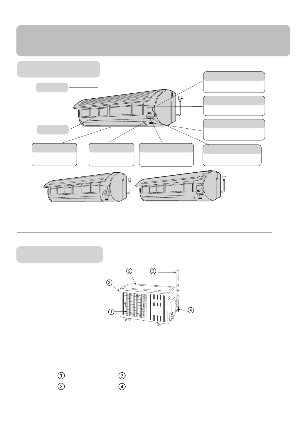
Indoor Unit
Inlet grille
Test running switch(manual)
Used only for test running in cooling
when room temp. is below 16
Don't use it in normal operation.
Emergency switch(manual)
Used when remote controller is lost or
defective. Unit will run temporaril
Remote signal receiver
Air filter
Horizontal flap
Use remote controller to
adjust up and down air flo
(Don't adjust it manually.)
Power indicator
w.
Lights up when unit starts.
Timer mode indicator
Lights up when
is selected.
Timer operation
A beeping sound is generated when
a signal from remote controller is
received.
Operation mode indicator
Lights up during compressor
running.
Actual inlet grille may vary from the one shown in the manual according to
the product purchased
o
C.
y.
Outdoor Unit
OUTLET
INLET
HSU-09LF03
HSU-12LF03
CONNECTING PIPING AND ELECTRICA
DRAIN HOSE
2
L WIRING
Parts and Functions
Operation
1
2
3
4
11
12
13
14
15
16
17
Clock set
ON/OFF
MODE SET
FAN
SWING
SLEEP
LOCK RESET
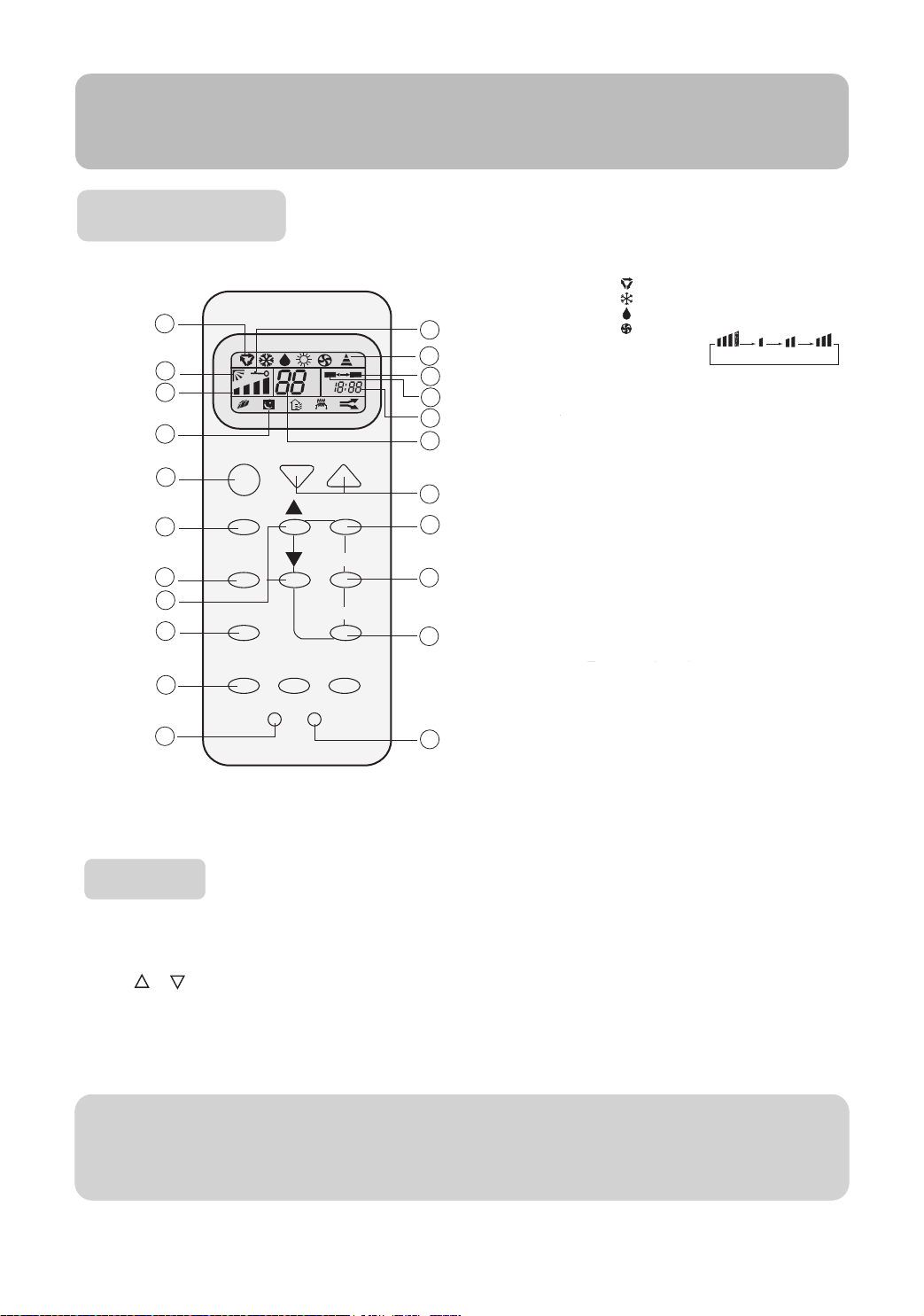
Buttons and display of the remote controller.
1. Mode display
AUTO
COOL
DRY
5
6
A
U
T
O
ON OFF
AM
o
PM
C
7
8
9
TEMP
TIMER
CLOCK
10
18
19
20
21
22
FAN
2. SWING display
3. FAN SPEED display
4. SLEEP display
5. LOCK display
6. SIGNAL SENDING
7. TIMER OFF display
8. TIMER ON display
9. CLOCK display
10. TEMP display
11. POWER ON/OFF
Used for unit start and stop.
12. MODE
Used to select AUTO run, COOL,
DRY and FAN operation
13. FAN
Used to select fan speed LO, MED, HI, AUTO
14. HOUR
Used to set clock and timer setting.
15. SWING
Used to set auto fan direction.
16. SLEEP
Used to select sleep mode.
17. LOCK
Used to lock buttons and LCD
display.
18. TEMP.
Used to select your desired temp.
19. SET
Used to confirm timer and clock settings.
20. TIMER
Used to select TIMER ON, TIMER OFF,
TIMER ON-OFF
21. CLOCK
Used to set correct time
22. RESET
Used to reset the controller back to
normal condition.
When unit is started for the first time and after replacing batteries in remote controller,
clock should be adjusted as follows:
Press CLOCK button, "AM" or "PM" flashes.
Press or to set correct time. Each press will increase or decrease 1min. If the
button is kept depressed, time will change quickly.
After time setting is confirmed, press SET, "AM "and "PM" stop flashing, while clock
starts working.
NOTE: Cooling only unit do not have displays and functions related with heating
LO MED HIAUTO
Hints
After replacing with new batteries, remote controller will conduct self-check, displaying
all information on LCD. Then, it will become normal.
3
Parts and Functions
Operation
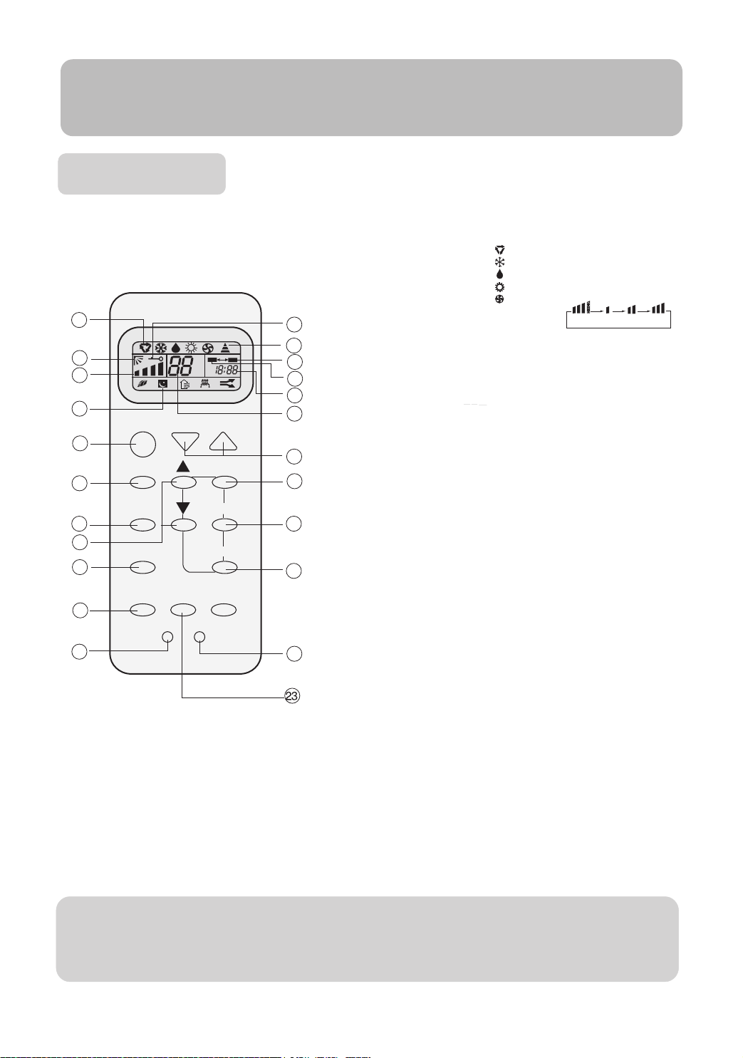
Buttons and display of the remote controller.
If the unit which you purchased has healthy function, Remote controller should
like the following figure:
1
ON
2
3
A
U
T
O
OFF
AM
o
PM
C
4
ON/OFF TEMP
11
MODE SET
12
13
14
15
16
17
FAN TIMER
SWING CLOCK
SLEEP
HEALTH
LOCK RESET
BRIEF INTRODUCTION TO HEALTH OPERATION
The anion generator in the air conditioner can generate a lot of anion to
effectively balance the quantity of position and anion in the air and also to kill
bacteria and speed up the dust sediment in the room and finally clean the air
in the room.
NOTE: Cooling only unit do not have displays and functions related with heating
5
6
7
8
9
10
18
19
20
21
22
1. Mode display
AUTO
COOL
DRY
HEAT
FAN
2. SWING display
3. FAN SPEED display
4. SLEEP display
5. LOCK display
6. SIGNAL SENDING
7. TIMER OFF display
8. TIMER ON display
9. CLOCK display
10. TEMP display
11. POWER ON/OFF
Used for unit start and stop.
12. MODE
Used to select AUTO run, COOL,
DRY, HEAT and FAN operation
13. FAN
Used to select fan speed LO, MED, HI, AUTO
14. HOUR
Used to set clock and timer setting.
15. SWING
Used to set auto fan direction.
16. SLEEP
Used to select sleep mode.
17. LOCK
Used to lock buttons and LCD
display.
18. TEMP.
Used to select your desired temp.
19. SET
Used to confirm timer and clock settings.
20. TIMER
Used to select TIMER ON, TIMER OFF,
TIMER ON-OFF
21. CLOCK
Used to set correct time
22. RESET
Used to reset the controller back to
normal condition.
23. HEALTH
Used to set healthy operation
AUTO
MED
LO
HI
Hints
After replacing with new batteries, remote controller will conduct self-check, displaying
all information on LCD. Then, it will become normal.
4
 Loading...