

Haier HSU-09HVd03, HSU-12HVd03, HSU-09HVd03/R2(SDB), HSU-12HVd03/R2(SDB) Operation Manual

Please read this operation manual before using the air conditioner.
0010515053
SPLIT TYPE ROOM AIR CONDITIONER
OPERATION MANUAL
Keep this operation manual for future reference.
Contents
2
3
6
7
1
CAUTIONS
PARTS AND FUNCTIONS
OPERATION
MAINTENANCE
TROUBLE SHOOTING
HSU-09HVd03/R2(SDB)
HSU-12HVd03/R2(SDB)
2
Loading of the battery
1
2
3
4
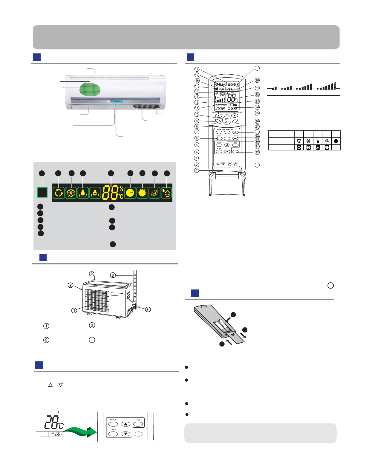
Parts and Functions
Indoor Unit
Remote controller
Remove the battery cover;
Load the batteries as illustrated.
2 R-03 batteries, resetting key
(cylinder);
Be sure that the loading
is in line with the
" + "/"-";
Load the battery,then put on the cover again.
The distance between the signal transmission head and the receiver hole should be within 7m without any obstacle as well.
When electronic-sta rted type fluorescent lamp or change- over
wireless telephone is installed in the
ver is apt to be disturbed in receiving
the signals,
so the distance to the indoor unit should be shorter.
type fluorescent lamp or
room, the recei
Note:
Full display or unclear display during operation indicates the
ries have been used up.
Please change batteries.
If the remote controller can't run normally during operation, please
reload several minutes later.
batte
remove the batteries and
Remove the batteries in case unit won't be in usage for a long period.
If there are any display
after taking-out, just need to press reset key.
Hint:
11. TIMER ON display
12
. FAN SPEED display
LOW HI
MED AUTO
13. LOCK display
14. SWING UP/DOWN display
15. SLEEP display
16. HEALTH display
18. Operation mode display
21. Left/right air flow display
22. TEMP display
23. TIMER OFF display
25. TEMP button
26. FAN button
27. HEALTH AIRFLOW button
28. SWING UP/DOWN button
29. SWING LEFT/RIGHT button
30.
FRESH
button
31. SET button
Used to lock buttons and LCD display.If
pressed,the other buttons will be disabled
and the lock condition display appears.
Press it once again,lock will be canceled
and lock condition display disappears.
33. LOCK
9. HEALTH button
10. ON/OFF button
Used to select CODE A or B with a press,
A or B will be displayed on LCD.
Please select A without special explanation.
1.CODE
When the remote controller appears
abnormal, use a sharp pointed article to
press this button to reset the remote
controller normal.
2.RESET
4. TIMER button
5. CLOCK button
6. SLEEP button
7. MODE button
8. HOUR button
3.LIGHT button
Control the lightening and extinguishing of
the indoor LED display board.
17.FRESH AIR display
19.Singal sending display
Operation m ode AU T O H E A T F A NCOOL DRY
Remotecontroller
Display board
20.UV light degerming function display
34.Ambient temp.display
24. TIMER/SLEEP display
FRESH
28
33
19
STERILIZE
When receiving the remote control signal,
display the set temperatrue and in the rest
time the room temperature is displayed and
this room temperature is only for reference.
32. STERILIZE button
Outdoor Unit
OUTLET
INLET
CONNECTING PIPING
AND ELECTRICAL WIRING
DRAIN HOSE
Clock set
Press CLOCK button, "AM" or "PM" flashes.
Press or to set correct time. Each press
change quickly.
After time setting is confirmed,press SET,
"AM "and "PM" stop flashing,while clock starts working.
or decrease 1min. If the
button is kept pressed,time will
will increase
Please be subject to the actual produce purchased the
above picture is just from your reference
Please be subject to the actual produce purchased the
above picture is just from your reference
STERILIZE
NOTE : The followingfunctions and related displays arenot available: 1
Inlet grille
Inlet
Outlet
Horizontal flap
(adjust up and down air flow
Don't adjust it manually)
(adjust left and
right air flow)
Vertical blade
(inside)
Anion generator
Display board
Air purifying
Filter(inside)
Singal receiver hole
COOL display
HEAT display
HEALTH display
Dry display
(If the unit which you purchased
has healthy function,follow it.
TIMER OFF display
TIMER ON display
SLEEP display
If not,please ignore.)
Ambient temp.display
When receiving the remote control signal,
display the set temperature and in the rest
this room temperature is only for reference.
time the room temperature is displayed and
AUTO display
FRESH AIR display
Display board
3
AUTO COOL DRY FAN HEAT
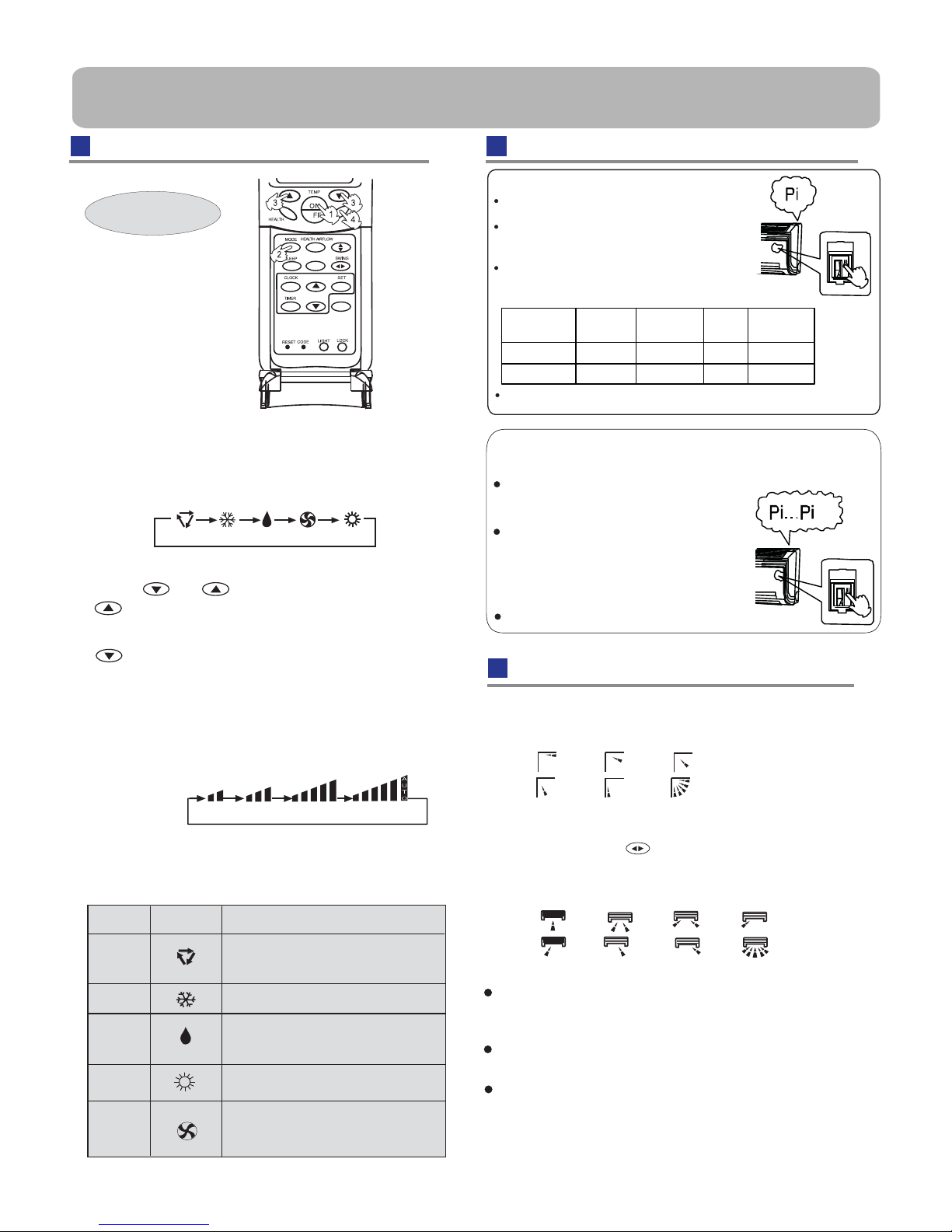
2.Select operation mode
Press FAN button. For each press, fan speed
follows:
Press MODE button. For each press, operation mode
changes as follows:
Remote controller:
Remote controller:
Press button
Every time the button is pressed, temp.setting
increase 1
o
C,if kept depressed, it will increase
rapidly
Every time the button is pressed, temp.setting
decrease 1
o
C,if kept depressed, it will
decrease rapidly
Select a desired temperature.
4.Fan speed selection
3.Select temp.setting
Air conditioner is running under displayed fan speed.
When FAN is set to AUTO, the air conditioner
automatically adjusts the fan speed according to room
temperature.
LOW
MED
HI
AUTO
1. Unit start
Press ON/OFF on the remote controller, unit starts.
Base Operation
Remote controller
changes as
32:(562)7
)5(6+
Emergency Operation:
temperature is below 16
o
C, do not use it in the
Test operation:
Use this switch in the test operation when the room
normal operation.
your finger from the switch: the cooling
Continue to press the test operation
switch for more than 5 seconds . After
you hear the "Pi" sound twice,
release
Test ope ration switch is the same as emergency switch.
operation starts with the air flow speed "Hi".
Emergency operation and test operation
Use this operation only when the remote controller
is defective or lost.
When the emergency ope
ration switch is
pressed,the" Pi "sound is heard once
, which
the start of this operation.
means
Unit won't restart until 3 minutes have
elapsed, due to
HEAT mode is not available on
cooling only unit.
It is advisable not to keep vertical flap at
downward position
or DRY mode, otherwise,
water might occur.
Cautions:
When humidity is high, condensate water
might occur at
louvers are adjusted to left or right.
for a long time in COOL
air outlet if all horizontal
system protection.
condensate
In this operation, the system automatically selects
the operation modes, cooling or heating, according
to the room temperature.
It is not poss ible to opera te in dry mode.
Tem p e ra t ur e
Operation
mode
Designated
temperature
Ti me r
mode
Air flow
ABOVE 23
O
C
BELOW 23
O
C
COOLING
HEATING
23
O
C
26
O
C
NO
NO
AUTOMATIC
AUTOMATIC
After 3 0 minutes, te st operation ends automatically.
Vertical flap
Pos.1
Pos.2
Pos.3
Pos.4
Pos.5
Pos.6
(Auto swing)
1.Status display of air sending
2.Left and right air flow adjustment
(manual)
Pos. 1
Pos. 2
Pos. 3
Pos. 4
Pos. 5
Pos. 6
Pos. 7
Pos. 8
For each press of button, remote controller
displays as follows :
remote controller:
Operation
Mode
AUTO
Remote
Controller
Note
COOL
DRY
HEAT
FAN
In DRY mode , when room temperature becomes
lower than temp.setting+2
o
C, unit will run
intermittently at LOW speed regardless of FAN
Under the mode of auto operation, air conditioner
will automatically select Cool or Heat operation
according to room temperature.
to AUTO, the air conditioner
automatically adjusts
temperature.
When FAN is set
the fan speed according to room
In FAN operation mode , the unit will not operate in
COOL or
HEAT mode but only in
FAN mode ,
AUTO is not available in
FAN mode.
And temp.
setting is disabled. In FAN mode, sleep operation
setting.
is not available.
Air Flow Direction Adjustm
Operation
 Loading...