

Haier HSU09VHJ, HSU09VHJDB Service Manual
SERVICE MANUAL
Order No.AC1101S020V0
DC Inverter
EA-Series
Model No. HSU09VHJ(DB)
©(Qingdao Haier Air Conditioner General corp.,Ltd)
All right reserved .Unauthorized copying and distribution is a violation of law
Haier Group
This service information is designed for experienced repair technicians only and is not designed for use by the general public.
It does not contain warnings or cautions to advise non-technical individuals of potential dangers in attempting to service a product.
Products powered by electricity should be serviced or repaired only by experienced professional technicians. Any attempt to service or
repair the product or products dealt with in this service information by anyone else could result in serious injury or death
WARNING
Wall mounted Type
14
14
41
41
41
25
20
49
49
50
66
70
70
82
9
HSU09VHJ(DB)-SM
of indoor unit
Main functions and control specifications of outdoor unit
Function of main thermistor
26
Value of thermistor
4
Service Diagnosis
49
Caution for diagnosis
M
3
Error codes and description indoor display
For indoor unit
For outdoor unit
10. Wiring Diagrams .......................................................................................... 91
10.1 Indoor Unit ...................................................................................................91
10.2 Outdoor Unit ................................................................................................92
11. Circuit Diagrams ...........................................................................................93
12. Description of Coding rules of Unit Model .................................................97

Introduction
1
Domestic Air Conditioner
1. Introduction
1.1 Safety Cautions
Be sure to read the following safety cautions before conducting repair work.
The caution items are classified into “Warning” and “Caution”. The “Warning” items are especially important
since they can lead to death or serious injury if they are not followed closely. The “Caution” items can also lead
to serious accidents under some conditions if they are not followed. Therefore, be sure to observe all the safety
caution items described below.
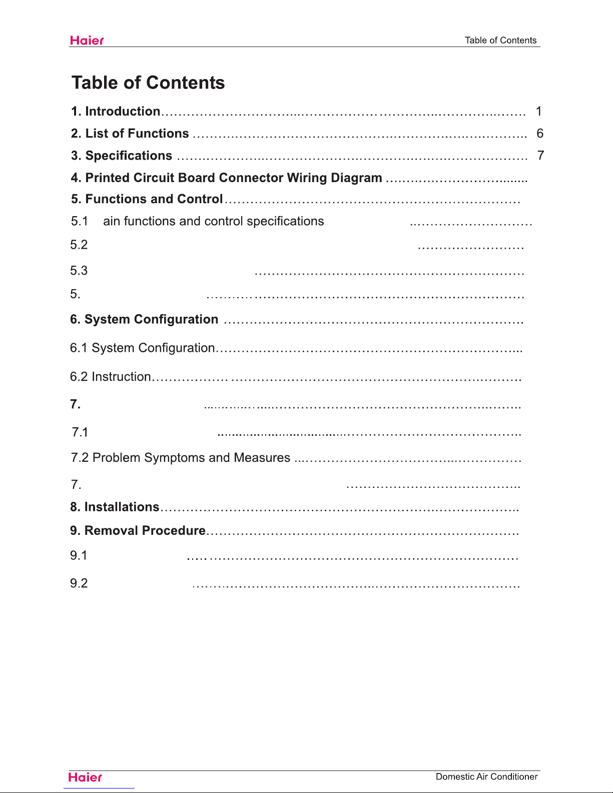
About the pictograms
This symbol indicates an item for which caution must be exercised.
The pictogram shows the item to which attention must be paid.
This symbol indicates a prohibited action.
The prohibited item or action is shown inside or near the symbol.
This symbol indicates an action that must be taken, or an instruction.
The instruction is shown inside or near the symbol.
After the repair work is complete, be sure to conduct a test operation to ensure that the equipment operates
normally, and explain the cautions for operating the product to the customer.
1.1.1 Caution in Repair
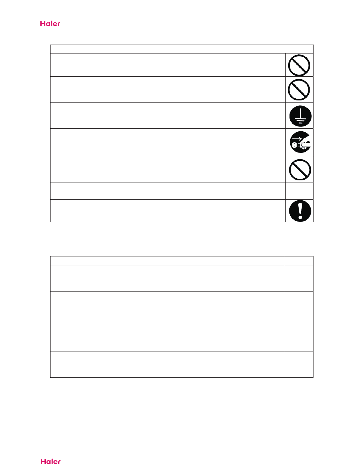
Warning
Be sure to disconnect the power cable plug from the plug socket before disassembling the equipment for
a repair.
Working on the equipment that is connected to a power supply can cause an electrical shook.
If it is necessary to supply power to the equipment to conduct the repair or inspecting the circuits, do not
touch any electrically charged sections of the equipment.
If the refrigerant gas discharges during the repair work, do not touch the discharging refrigerant gas.The
refrigerant gas can cause frostbite.
When disconnecting the suction or discharge pipe of the compressor at the welded section, release the
refrigerant gas completely at a well-ventilated place first.
If there is a gas remaining inside the compressor, the refrigerant gas or refrigerating machine oi l
discharges when the pipe is disconnected, and it can cause injury.
If the refrigerant gas leaks during the repair work, ventilate the area. The refrigerant gas can generate
toxic gases when it contacts flames.
The step-up capacitor supplies high-voltage electricity to the electrical components of the outdoor unit.
Be sure to discharge the capacitor completely before conducting repair work.A charged capacitor can
cause an electrical shock.
Do not start or stop the air conditioner operation by plugging or unplugging the power cable plug.
Plugging or unplugging the power cable plug to operate the equipment can cause an electrical shock or
fire.
HSU09VHJ(DB)-SM
Introduction
2
Domestic Air Conditioner
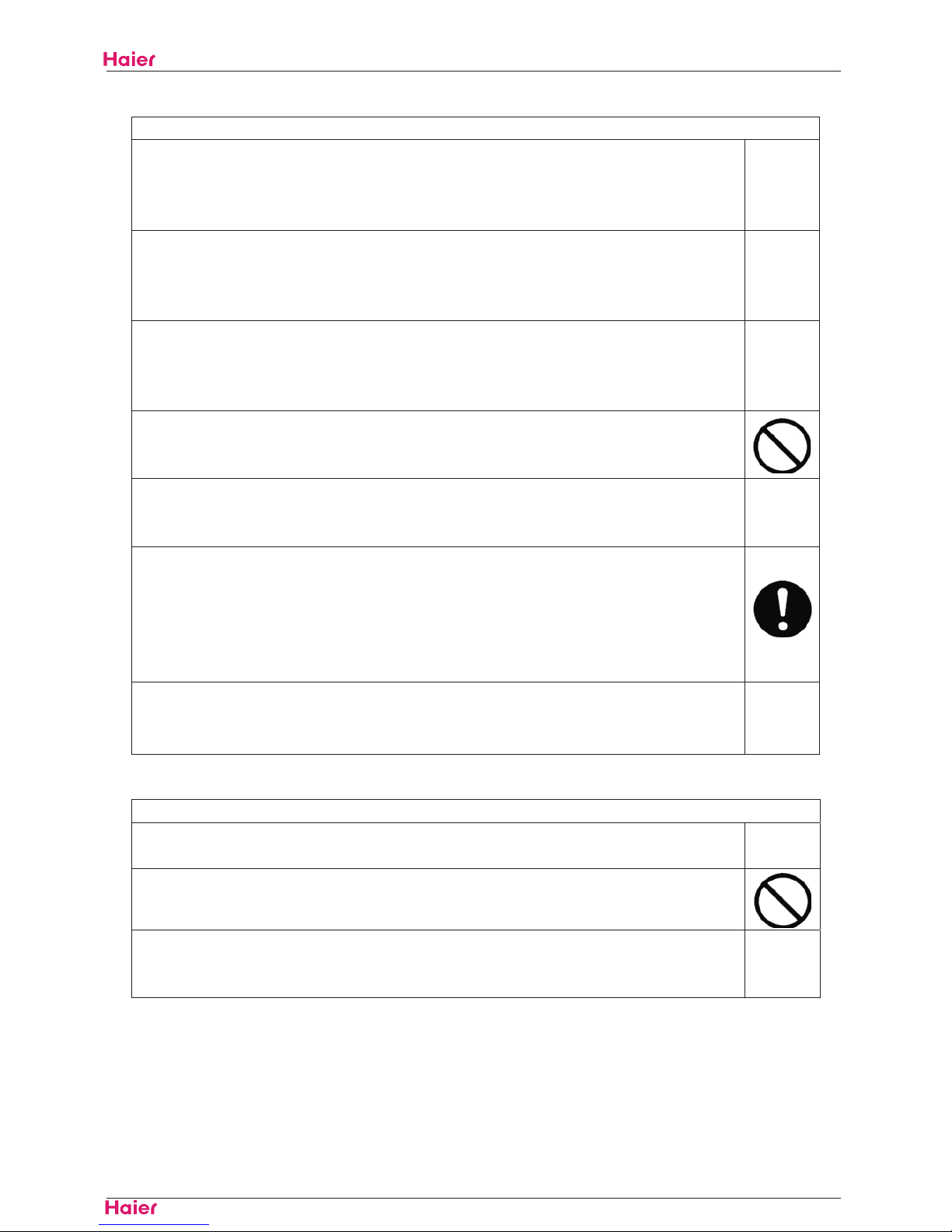
Warning
Do not repair the electrical components with wet hands. Working on the equipment with wet hands can
cause an electrical shock.
Do not clean the air conditioner by splashing water. Washing the unit with water can cause an electrical
shock.
Be sure to provide the grounding when repairing the equipment in a humid or wet place, to avoid electrical
shocks.
Be sure to turn off the power switch and unplug the power cable when cleaning the equipment. The
internal fan rotates at a high speed, and cause injury.
Do not tilt the unit when removing it. The water inside the unit can spill and wet the furniture and floor.
Be sure to check that the refrigerating cycle section has cooled down sufficiently before conducting repair
work. Worki ng on the unit when the refrigerating cycle secti on is hot can cause burns.
Use the welder in a well-ventilated place. Using the welder in an enclosed room can cause oxygen
deficiency.
1.1.2 Cautions Regarding Products after Repair
Warning
Be sure to use parts listed in the service parts list of the applicable model and appropriate tools to
conduct repair work. Never attempt to modify the equipment. The use of inappropriate parts or tools can
cause an electrical shock, excessive heat generation or fire.
When relocating the equipment, make sure that the new installation site has sufficient strength to
withstand the weight of the equipment.
If the installation site does not have sufficient strength and if the installation work is not conducted
securely, the equipment can fall and cause injury.
Be sure to install the product correctly by using the provided standard installation frame.
Incorrect use of the installation fram e and improper installation can cause the equipm ent to fall, resulting
in injury.
For
integral
units only
Be sure to install the product securely in the installation frame mounted on a window frame.
If the unit is not securely mounted, it can fall and cause injury.
For
integral
units only
HSU09VHJ(DB)-SM
Introduction
3
Domestic Air Conditioner
Warning
Be sure to use an exclusive power circuit for the equipment, and follow the technical standards related to
the electrical equipment, the internal wiring regulations and the instruction manual for installation when
conducting electrical work.
Insufficient power circuit capacity and improper electrical work can cause an electrical shock or fire.
Be sure to use the specified cable to connect between the indoor and outdoor units. Make the
connections securely and route the cable properly so that there is no force pulling the cable at the
connection terminals.
Improper connections can cause excessive heat generation or fire.
When connecting the cable between the indoor and outdoor units, make sure that the terminal cover does
not lift off or dismount because of the cable.
If the cover is not mounted properly, the terminal connection section can cause an electrical shock,
excessive heat generation or fire.
Do not damage or modify the power cable.
Damaged or modified power cable can cause an electrical shock or fire. Placing heavy items on the
power cable, and heating or pulling the power cable can damage the cable.
Do not mix air or gas other than the specified refrigerant (R-410A / R22) in the refrigerant system.
If air enters the refrigerating system, an excessively high pressure results, causing equipment damage
and injury.
If the refrigerant gas leaks, be sure to locate the leak and repair it before charging the refrigerant. After
charging refrigerant, make sure that there is no refrigerant leak.
If the leak cannot be located and the repair work must be stopped, be sure to perform pump-down and
close the service valve, to prevent the refrigerant gas from leaking into the room. The refrigerant gas itself
is harmless, but it can generate toxic gases when it contacts flames, such as fan and other heaters,
stoves and ranges.
When replacing the coin battery in the remote controller, be sure to disposed of the ol d battery to prevent
chil dren from swallowing it.
If a child swallows the coin battery, see a doctor immediately.
Caution
Installation of a leakage breaker is necessary in some cases depending on the conditions of the
installation site, to prevent electrical shocks.
Do not install the equi pment in a place where there is a possibility of combusti ble gas leaks.
If a combustible gas leaks and remains around the unit, it can cause a fire.
Be sure to install the packi ng and seal on the installation frame properly. If the packing and seal are not
installed properly, water can enter the room and wet the furniture and floor.
For
integral
units only
HSU09VHJ(DB)-SM
Introduction
4
Domestic Air Conditioner
1.1.3 Inspection after Repair
Warning
Check to make sure that the power cable plug is not dirty or loose, then insert the plug into a power outlet
all the way.
If the plug has dust or loose connection, it can cause an electrical shock or fire.
If the power cabl e and lead wires have scratches or deteriorated, be sure to replace them.
Damaged cable and wires can cause an electrical shock, excessive heat generation or fire.
Warning
Do not use a joined power cable or extension cable, or share the same power outlet with other el ectrical
appliances, since it can cause an electrical shock, excessive heat generation or fire.
Caution
Check to see if the parts and wires are mounted and connected properly, and if the connections at the
soldered or crimped terminals are secure. Improper installation and connections can cause excessive
heat generation, fire or an electrical shock.
If the installation platform or frame has corroded, replace it. Corroded installation platform or frame can
cause the unit to fall, resulting in injury.
Check the grounding, and repair it if the equipment is not properly grounded. Improper grounding can
cause an electrical shock.
Be sure to measure the insulation resistance after the repair, and make sure that the resistance is 1 M
ohm or higher.
Faulty insulation can cause an electrical shock.
Be sure to check the drainage of the indoor unit after the repair.
Faulty drainage can cause the water to enter the room and wet the furniture and floor.
HSU09VHJ(DB)-SM

,QWURGXFWLRQ
'RPHVWLF$LU&RQGLWLRQHU
8VLQJ,FRQV
,FRQVDUHXVHGWRDWWUDFWWKHDWWHQWLRQRIWKHUHDGHUWRVSHFLILFLQIRUPDWLRQ7KHPHDQLQJRIHDFKLFRQLVGHVFULEHGLQ
WKHWDEOHEHORZ
8VLQJ,FRQV/LVW
,FRQ 7\SHRI,QIRUPDWLRQ 'HVFULSWLRQ
1RWH 1RWH
$³QRWH´SURYLGHVL QIRUPDWLRQWKDWLVQRWLQGLVSHQVDEOHEXWPD\
QHYHUWKHOHVVEHYDOXDEOHWRWKHUHDGHUVXFKDVWLSVDQGWULFNV
&DXWLRQ
&DXWLRQ
$³FDXWLRQ´LVXVHGZKHQWKHUHLVGDQJHUWKDWWKHUHDGHUWKURXJK
LQFRUUHFWPDQLSXODWLRQPD\GDPDJHHTXLSPHQWORRVHGDWDJHWDQ
XQH[SHFWHGUHVXOWRUKDVWRUHVWDUWSDUWRIDSURFHGXUH
:DUQLQJ :DUQLQJ $³ZDUQLQJ´LVXVHGZKHQWKHUHLVGDQJHURISHUVRQDOLQMXU\
5HIHUHQFH
$³UHIHUHQFH´JXLGHVWKHUHDGHUWRRWKHUSODFHVLQWKLVELQGHURULQ
WKLVPDQXDOZKHUHKHVKHZLOOILQGDGGLWLRQDOLQIRUPDWLRQRQD
VSHFLILFWRSLF
HSU09VHJ(DB)-SM
09
HSU09VHJ(DB)
1090( 0-1 )
190(2
0-14 0)
16.8
8
7. 2
6. 3
46/ 43/39
54
54
5.4 5.9
3.93(1.35-4.1)
52.98
61.24
HSU09VHJ(DB)
3.51(1.47-4.1)
3018.6(1260-3520)
3380(1160-3530)
7
3/8
inches
pints/hr
feet
feet
feet
OZ/inches
inches
inches
lbs
lbs
inches
inches
5/8
0.018
1/4
SL
4.8
4.8
30
2.82
36 15/16 x 7 3/8 x 10 7/16
39 5/16 x 10 5/16 x 12 7/16
8
7. 2
6. 3
33
33
0.1
5
0.15
4
12000(5000-14000 ) 13400(4600-14000)
SEER/HSPF
9.5
49 3/16
32 13/16
32 13/16
HSU09VHJ(DB)-SM
R410a
35.5
79.37
72.75
49
63
59
21 3/8 x 30 13/16 x 10 1/16
23 9/16 x 36 x 12 13/16
780 780
3.5
3.5
53
20
80
650
ESTER OIL VG74
Rotary Compressor
8
31.6
1115
31.6
1115
0.65
DA89X1C-20FZ
HSU09VHJ(DB)-SM
oz
pints
80 F
67 F
95 F
75 F
70 F /60° FWB
47 F 47 F
Ibs
Ibs
16 3/8 feet
inches
inches

HSU09VHJ˄DB˅-SM
Connector Wiring Diagram
Domestic Air Conditioner
9
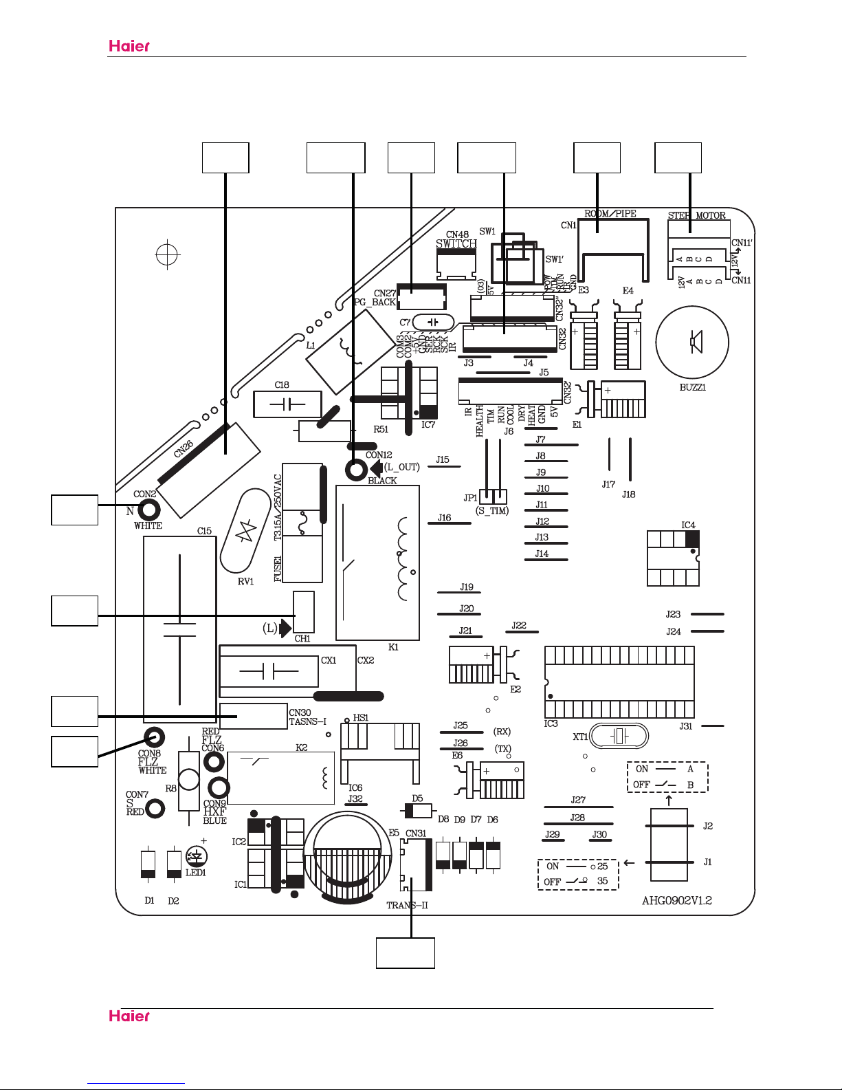
3ULQWHG&LUFXLW%RDUG&RQQHFWRU:LULQJ'LDJUDP
4.1᧶Indoor unit Connectors
Connectors
PCB(1) (Control PCB)
1) CN26 Connector for fan motor
2) CN11 Connector for STEP motor
3) CN8 Connector for heat exchanger thermistor and Room temperature thermistor
4)CN27 Connector for fan feedback
5)CH1 Connector for power L wire
6)CON2 Connector for power N wire
7) CON7 Connector for communicate wire
8) CN30 Connector for transformer input
9) CN31 Connector for transformer output
10) CN32 Connector for display board
Note: Other designations
PCB(1) (INdoor Control PCB)
1) CN48 Connector for Forced operation ON / OFF switch
2) J1 Select 25 or 35
3) LED1 communicate display light
4) RV1 Varistor
5) FUSE1 Fuse 3.15A/250VAC
HSU09VHJ˄DB˅-SM
Connector Wiring Diagram
Domestic Air Conditioner
10
PCB(1)
CN31
CN11CN1 CN32 CN26 CN27
CON2
CN30
CON12
CON8
CH1
HSU09VHJ˄DB˅-SM
Connector Wiring Diagram
Domestic Air Conditioner
11
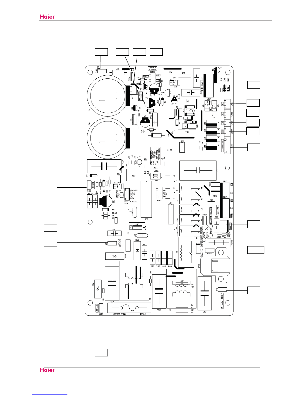
4.2 ᧶outdoor unit
Connectors
PCB(1) (Control PCB)
1) CN1,CN2 Connector for power N and L
2) CN3 Connector for ground
3) CN22 Connector for DC POWER 15Vand 5V to the module board
4) CN16 Connector for electric expansion valves
5) CN21 Connector for DC fan motor
6) CN10 Connector for four way valve coil
7) CN17,CN18,CN19,CN20 Connector for thermistors
(CN20: outdoor air,CN19: heat exchanger, CN18 :SUCK thermistors ,CN17 :discharge pipe)
8) CN23 Connector for communicate between the control board and the module board
9) CN25 ,CN8 Connector for the L,N to the module board
10) CN4 Connector for communicate between the indoor board and the outdoor board
11) CN26 Connector for capacitance anode
12) CN24 Connector for capacitance cathode
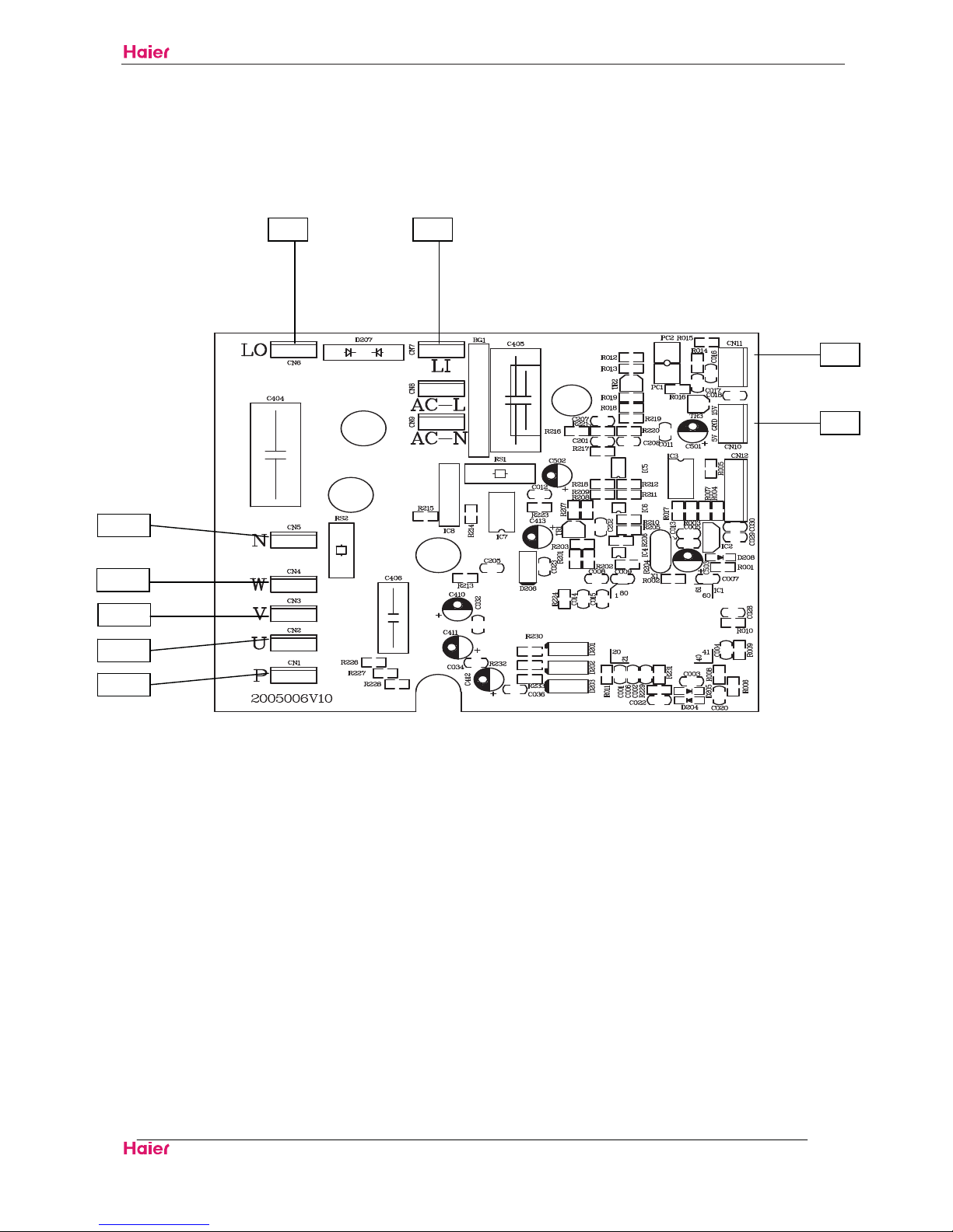
PCB(2) (module PCB)
CN10 Connector for the DC power 5V and 15V form the control PCB
CN11 Connector for communicate between the control board and the module board
P( CN1), N(CN5) Connector for capacitance board
LI (CN7),LO(CN6) Connector for reactor
CN2ˈCN3ˈCN4 Connector for the U, V, W wire of the
compressor
Note: Other Designations
PCB(1) (Control PCB)
1) FUSE 1, (25A,250VAC) FUSE 2(1A,250VAC)
2)LED 1 keep light representative normal ,if keep flash interval representative trouble Alarm
3)RV1,RV2,RV3 Varistor
HSU09VHJ˄DB˅-SM
Connector Wiring Diagram
Domestic Air Conditioner
12
PCB(1)
CN2
CN1
CN4
CN8
CN25
CN26 CN24 CN23 CN22
CN17
CN18
CN19
CN20
CN16
CN21
CN10
CN3
HSU09VHJ˄DB˅-SM
Connector Wiring Diagram
Domestic Air Conditioner
13
PCB(2)
CN1
CN2
CN3
CN4
CN5
CN6
CN7
CN11
CN10
HSU09VHJ˄DB˅-SM
Funcitions and Control
Domestic Air Conditioner
14
5.Funcitions and Control
5.1 Main functions and control specification of indoor unit
This specification use for HSU18VHJ˄DB˅frequency conversion air condition are manufactured
by Haier air condition parent company. "Setting value" (express in parameter) in this specification
means is a parameter that is stored in EEPROM. Refer to [EEPROM parameter table].
5.1.1 Temperature Adjusting function
5.1.1.1 Temperature adjusting of different levels.
(DASH operation conditions under different modes)
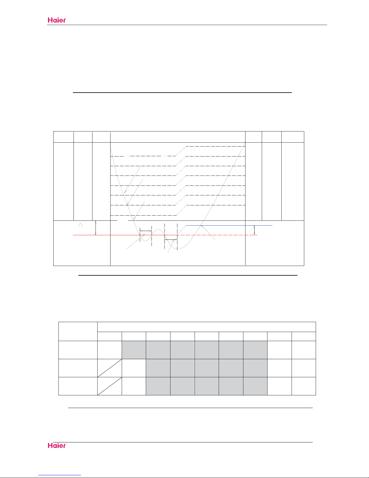
5.1.1.2 Select the wind volume when it is set automatic
When the wind volume is automatic, it can be switched between strong, medium and weak according
to the temperature adjusting levels.
Wind volume under the automatic wind volume mode
Temperature adjusting levels
A B C D E F G H I
Heating
Strong Strong Strong Strong Strong Medium Weak Weak SLO
cooling
Strong Strong Strong Medium Medium Weak Weak Weak
Moisture
removing
Strong Medium Medium Medium Weak Weak SLO SLO
&22/
+($7'$6+
%
0,187(63527(&7,21
&22/'$6+
'5<'$6+
7
&20367$576$*$,1
(
*
)
+
'
&
&22/'5< +($7
(
%/2&.
$
+($7
'5<
V
HSU09VHJ˄DB˅-SM
Funcitions and Control
Domestic Air Conditioner
15
5.1.1.3 Wind volume limit
When the compressor is working and the max setting for indoor fan motor is medium or weak, the
upper limit of indicated frequency is as follows:
Frequency control form for wind volume
Limited frequency
variables
Limited frequency
Medium wind volume FQLIMMD 70Hz
Weak wind volume FQLIMLO 58Hz
Limited frequency for
up/down health wind
FUPHEAL 48Hz
5.1.2 Main functions
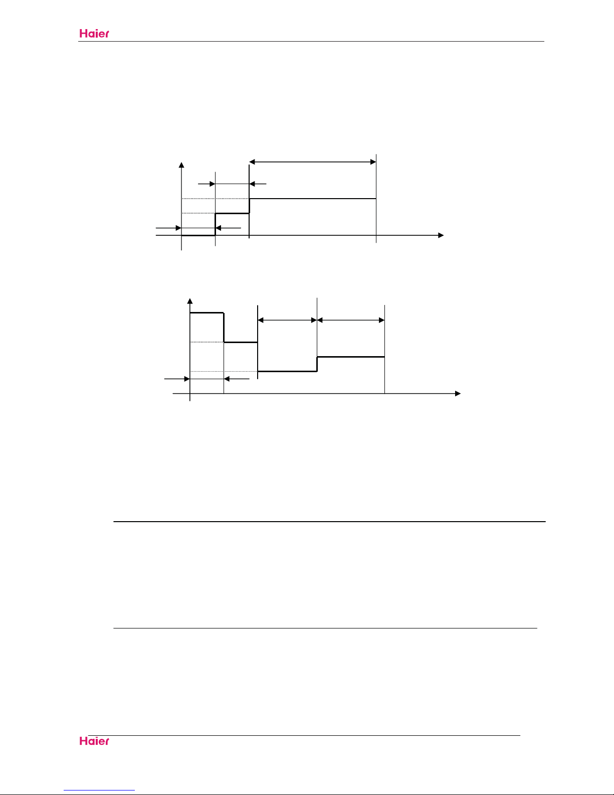
5.1.2.1 Warm boot
When the heat running starts or the frost removing ends and the compressor starts again, in order to
avoid cold wind, warm boot wind volume control should be done.
Heat exchange temperature
THHOT3喈37ć˅
THHOT2喈35ć喉
THHOT1喈25ć喉
THHOTR喈23ć˅
4 minutes
Stop weak setting weak stop
To control the indoor fan motor as shown in the table above according to the heat exchange
temperature
The fan motor stops when the heat exchange temperature is below 25ć
The fan motor is working slightly weak when the heat exchange temperature is above25 ć and
below 35ć
The fan motor is working weak when the heat exchange temperature is above35 ć and below 37ć
The fan motor works as set if the he heat exchange temperature remains above 38ć
slightly
weak
slightly
weak
HSU09VHJ˄DB˅-SM
Funcitions and Control
Domestic Air Conditioner
16
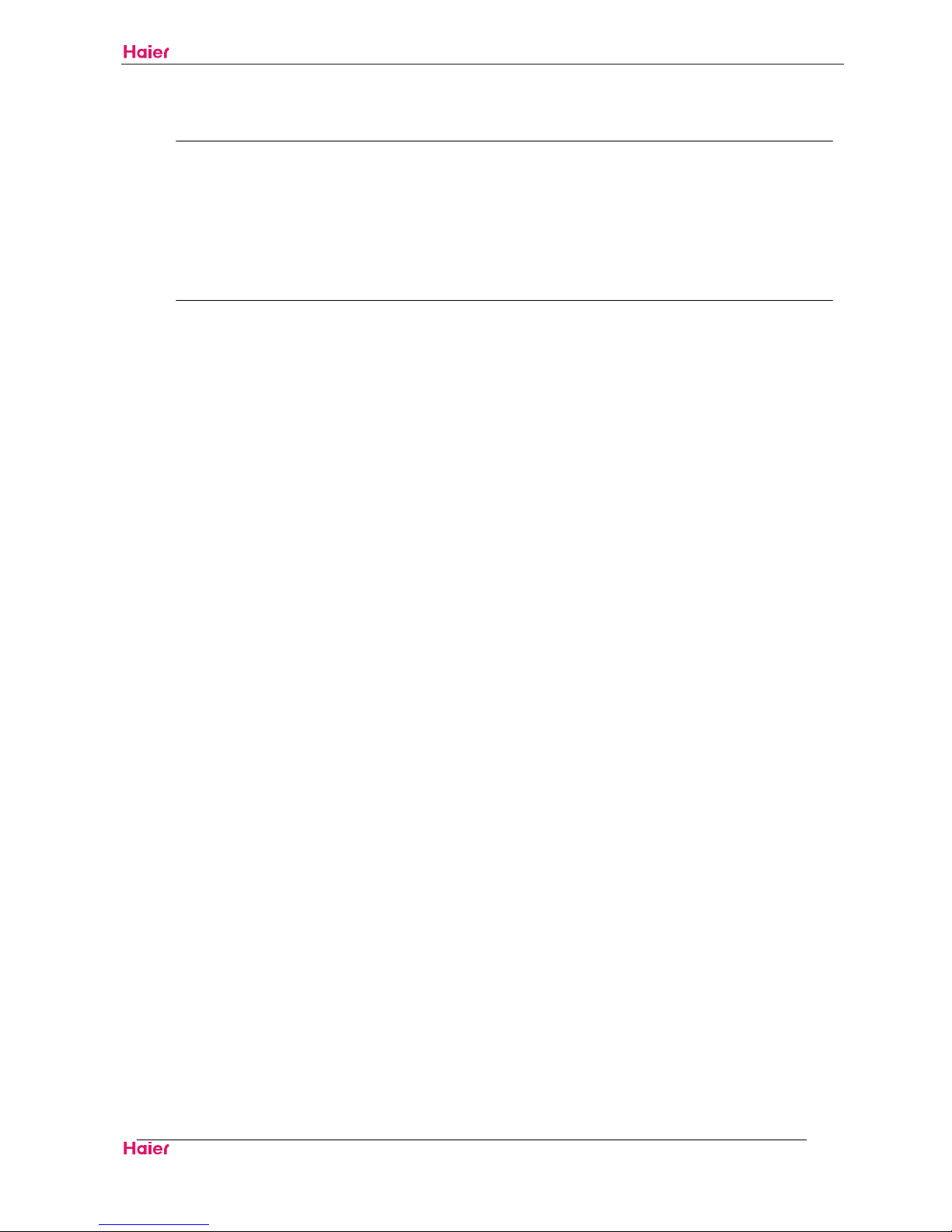
5.1.2.2 When the compressor stops and remains idle for 3 minutes
20 seconds after the compressor stops, the up wind volume is weak (switching to SSLO in silent
running mode) and then slightly weak. While the down wind volume is stoped
If the compressor stops when the heat running starts, the wind volume is weak
5.1.2.3 Dehumidification running
Under the dehumidification mode the fan motor stops as the compressor stops
The operation is weak after 3 minutes’ idle mode
After stand by for 3 minutes, the compressor is on.
The compressor operates as the set wind volume when the wind volume is set to be strong, medium
or weak
The wind volume is decided according to the temperature adjusting when the wind volume is set to be
automatic.
Moisture removing running
Level H 3minutes idle mode
Compressor
OFF
Setting slightly OFF weak weak setting
weak
5.1.2.4 Automatic running
When the running mode is turned to automation after starting the system, the system will first
determine the running mode according to the current room temperature and then will run according to
the determined mode. Tr in the following selection conditions means room temperature, Ts means
setting temperature, Tp means temperature of indoor coil pipe
Tr23 Choose Cooling Modeć
Tr˘23 Choose Heating Modeć
After turning to the automation mode, the running mode can be switched between cooling mode, fan
mode and heating mode according to the change of the indoor ambient temperature. But the
automatic conversion between cooling mode and heating mode must be conducted after 15 minutes.
5.1.3 Special functions
5.1.3.1 Powerful running
Powerful running for 15 minutes
The running stops or ends the powerful running after 15 minutes
The mode switch ends the powerful running
Enter into the silent mode, normal running mode or timed switching on mode to end the powerful
running
HSU09VHJ˄DB˅-SM
Funcitions and Control
Domestic Air Conditioner
17
When in automatic mode, there are powerful and silent functions for your choice. When the main unit
is in cooling mode, it operates with powerful cooling or silent cooling. When the main unit is in heating
mode, it operates with powerful heating or silent heating. When the main unit is in wind-sending mode,
there are no powerful or silent modes.
There is no powerful mode for wind-sending and moisture removing
Powerful heating
˖
Change the set temperature. With temperature adjusting function
The wind volume is the automatic medium
When in frost removing mode, the outdoor unit does not accept the communication signal for powerful
running
After 15 minutes of powerful running, the compressor can not be off within 10 minutes
Powerful cooling
˖
Change the set temperature. With temperature adjusting function
The wind volume is the automatic strong
After the compressor starts, there will be no low-intense running protection within 3 minutes
5.1.3.2 Silent running
Send the silent running signal to the outdoor unit
Under the Silent hearing mode,The wind volume is SSLO after the compressor is on,The wind volume
will be kept SSLO within 20 seconds after the compressor stops and then changes to weak
Under the Silent cooling mode the wind volume is SSLO
There is no silent mode for moisture removing and wind-sending.
5.1.3.3 Air cleaning
I
f the fan motor starts working after receiving the remote-control order, the aion generator starts
working and sends out ions.
The ion generator stops as the fan motor stops.
When the ion generator is OFF and the air cleaning function is on, the fan motor starts running and
the ion generator starts working again.
5.1.3.4 Timed running
Set the time duration according to the time difference between the clock for
timing and the current clock
In timing mode, the display panel will flash the light at fixed times
Timed When this function is set, operation modes on the panel display will not
OFF change. The timing icon will show and the operation stops when the set time comes.
Timed When this function is on, the panel display will only display a question mark.
ON The unit will operate as the set mode when the time comes.
Timed The unit will start operating or stop according to the order of your setting.
ON/OFF
HSU09VHJ˄DB˅-SM
Funcitions and Control
Domestic Air Conditioner
18
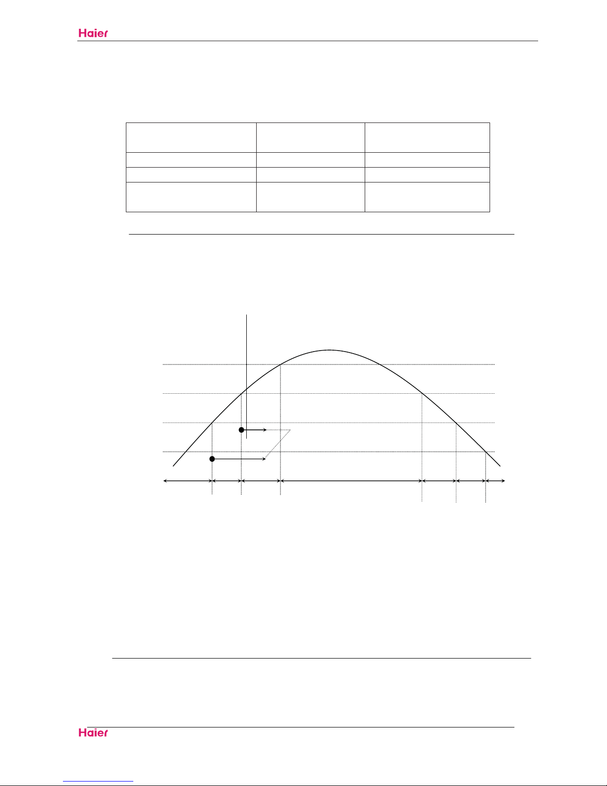
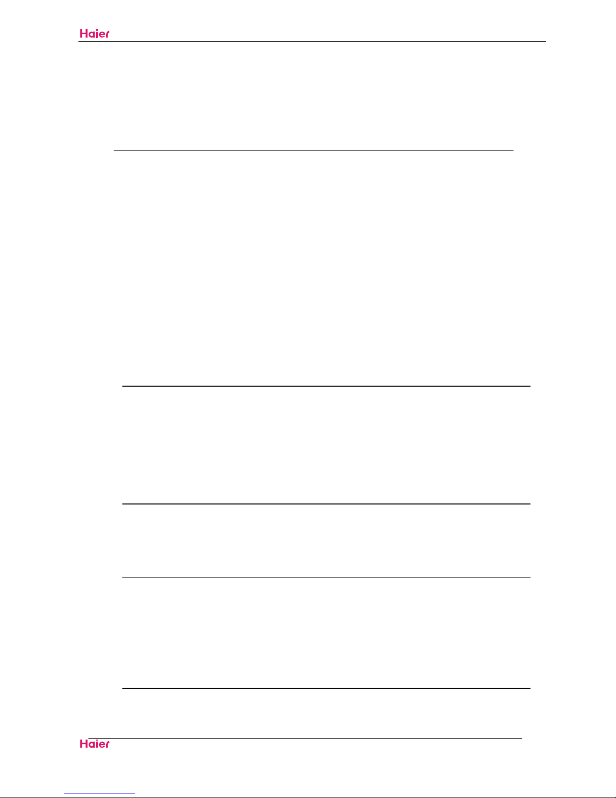
5.1.3.5 Sleeping function
a.
After setting the sleeping function, the refrigerating mode and dehumidification mode will run as per
the following rules:
1 hour 1 hour 6hours
T()
Ts+4
Ts+2
Ts Sleep OFF t(hour)
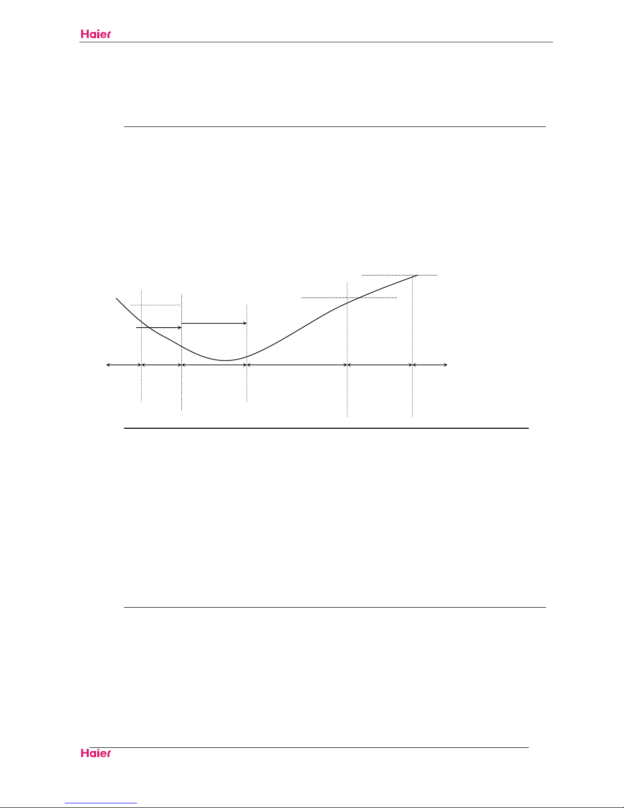
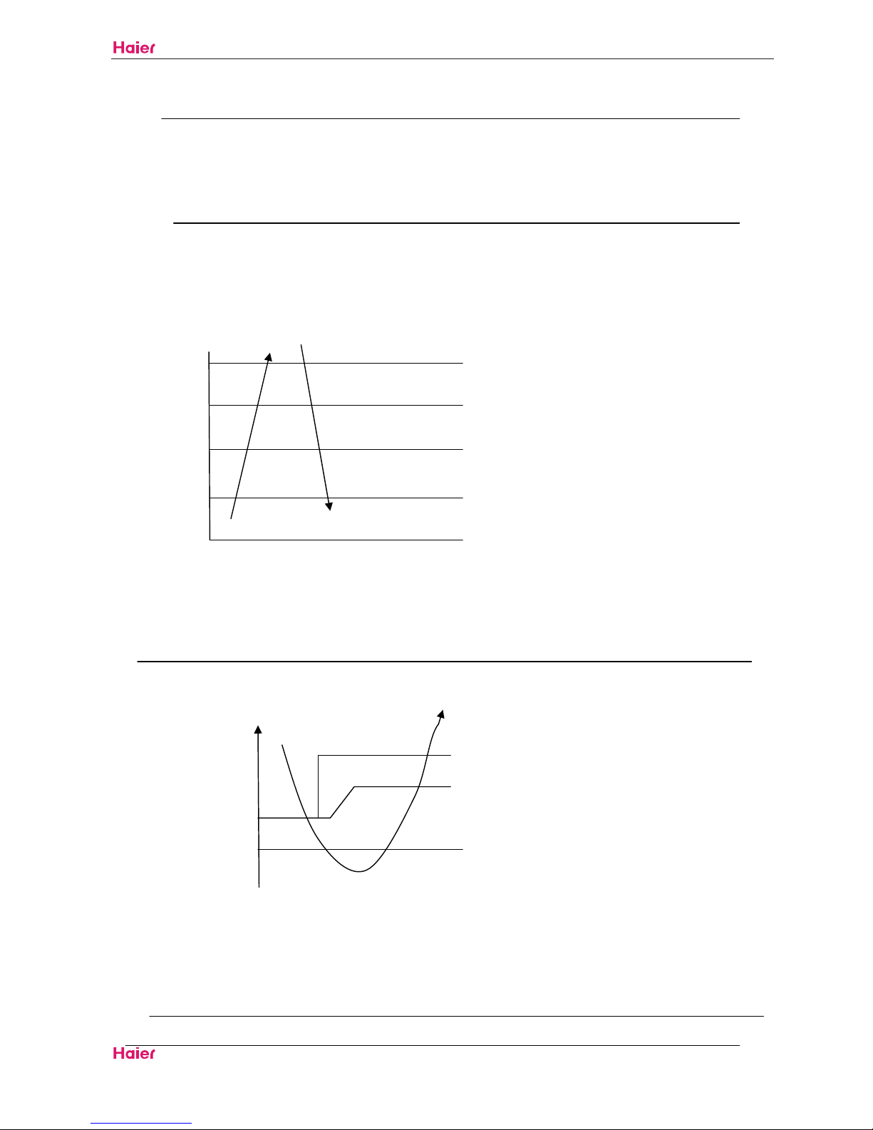
b.After setting the sleeping function, the heating mode will run as per the following rules:
T() 1 hour 1 hour 3hours 3hours
Ts
Ts-4
Ts-6
Ts-8
Ts Sleep OFF t(hour)
As shown in the above diagram, after running for 1 hour under refrigerating mode and
dehumidification mode, the setting temperature will increase about2
; after another 1 hour, it will
increase about2
again, and after 6 hours, it will cease; after running for 1 hour under heating
mode, the setting temperature will decrease about4
, after another 1 hour, it will decrease the
about 4
again, and after 3 hours, it will increase about 2 , and after other 3 hours, it will cease.ć
5.1.3.6 Trial running
The indicated frequency for trial running is 58Hz, wind volume is strong.
The trial running will last for 30 minutes and then the unit will be powered off. The unit will exit the trial
running if it receives any remote-control signal during the trial running period.
There is no low-intense running protection.
5.1.3.7 Power failure compensation
To enter into the function please press the sleep key 10 times with 4 beeps in 7 seconds
Under the power failure compensation mode, unplug and plug again ,the indoor unit will resume
original operation
Under the power failure compensation mode, unplug and plug again, the unit will be on OFF state.
Mode, Fan speed, Healthy, Set temperature can be memoried. Swing, Timer, Sleep cannot be
HSU09VHJ˄DB˅-SM
Funcitions and Control
Domestic Air Conditioner
19
memoried
Press the sleep key for 10 times with 2 beeps in 7 seconds to exit.
5.1.3.8 Rated Operation
Rated Cooling:
When receiving the instruction of indoor unit rated operation, the unit will start rated cooling operation.
Rated Heating:
When receiving the instruction of indoor unit rated operation, the unit will start rated heating operation.
HSU09VHJ˄DB˅-SM
Funcitions and Control
Domestic Air Conditioner
20
5.2 Main functions and control specification of outdoor unit
Sensor Code Definition: Tai= Indoor Ambient Temperature, Tao=Outdoor Ambient Temperature,
Tc1=Indoor Coil, Td= Air Discharge, Te= Outdoor Coil, Ts=Air Intake
5.2.1 Outdoor Unit Operation Frequency and Control
Compressor Operation Frequency Range
Compressor Operation Frequency Range:
Outdoor Temperature
İ4 4ī18 ı18
Heating˄Hz˅ 20ī110 20ī90 20ī53
Defrosting˄Hz˅
80
Outdoor Temperature
İ23 23ī32 ı32
Cooling˄Hz˅ 20ī50 20ī70 20ī95
Compressor Startup
Regardless of target frequency of indoor unit, each time when compressor is from off to on, it
must maintain 60Hz,90Hz for one minute (Frequency will be immediately decreased under the
condition that outdoor unit air discharge temperature overheating protection is activated or over
current of compressor) then the compressor will operate towards target frequency. This process
does not exist in normal operation of unit.
Heating
When completing compressor startup operation, it will operate as per frequency of indoor unit.
After 2 minutes, compressor operation frequency will be compensated as per relevant conditions.
Cooling & Dehumidification:
When completing compressor startup operation, it will operate as per frequency of indoor unit.
After 2 minutes, compressor operation frequency will be compensated as per relevant conditions.
Compressor Frequency Increase/Decrease Speed
Rapid Frequency Increase/Decrease Speed 1 ----------1Hz/s
Slow Frequency Increase/Decrease Speed 2 -----------1Hz/10s
HSU09VHJ˄DB˅-SM
Funcitions and Control
Domestic Air Conditioner
21
5.2.2 Outdoor fan control
Compressor startup within 3min ,outdoor fan speed control as follows:
Outdoor
Temperature
ī ı
Cooling/
Dehumidification
Heating
fter compressor runs 3min ,outdoor fan speed control as follows:
Cooling/ Dehumidification:
Compressor Operation Frequency˄Hz˅ ī ı
7DR˄ć˅
ī
ī
ı
Heating:
Compressor Operation Frequency˄Hz˅ ī ı
7DR˄ć˅
İ
ī
ı
Compressor shutdown and outdoor fan residual heat blow process
When compressor shuts down in cooling mode, outdoor fan automatically jumps to low speed and
blows residual heat for 30s and stop.
5.2.3 Four-way Valve Control
Defrosting Four-way Valve Controlˈ(please see defrosting process for details)
Time sequence of the defrosting operation is as follows:
Four-way Valve Work Status in Other Modes:
In heating mode, four-way valve is on. If compressor is off or is switched to non-heating mode,
four-way valve ensures that it is off at least 2 minutes after compressor shuts down.
5.2.4 Outdoor Defrosting Control
Defrosting Mode Entry Conditions
The unit will enter defrosting mode when compressor starts up and operates for 10 minutes
continuously in heating mode or after compressor runs for an accumulated time of 45 minutes (Upon
completion of defrosting or when switched to cooling mode, compressor accumulated operation time
will be cleared) and when 2 minutes’ continuous checking by defrosting sensor TE (check frosting
condition of outdoor unit heat exchanger) and outdoor ambient temperature sensor TA meets the
following conditions:
HSU09VHJ˄DB˅-SM
Funcitions and Control
Domestic Air Conditioner
22
TEC×TAˉĮ
Among which: C:TA˘0ćˈC=0.8
TA0ćˈC=0.6
For area prone to frost, the value is set at 6 when unit leaves the factory.
Defrosting entry temperature control -15 C×TAć ˉĮ-5ć
Defrosting Time Interval
time interval between two defrosting cycles is 45 minutes.
Defrosting Operation
When defrosting begins, compressor will stop for one minute, external fan is running and 50s later,
four-way valve will be off.
When compressor starts, external fan will be off, compressor will run at 58Hz for 60s then move on to
target frequency of 88Hz.
During defrosting, compressor current and air discharge overheat protection features are effective.
During defrosting, if compressor shuts down due to activation of protection feature or due to
malfunction, it will resume after 3 minutes. In the unit is still within defrosting cycle, it will resume
defrosting and startup of compressor will be based on the rule for defrosting startup. (The unit will exit
defrosting mode and handle fault in the event of 3 consecutive restart failures.)
On entering defrosting, it must guarantee that compressor will operate for a minimum of 2 minutes in
defrosting mode before exit.
Defrosting Exit Condition
When one of the following conditions is met, defrosting operation will be switched to heating
operation.
˄1˅:Temperature of outdoor heat exchanger exceeds 7 for 80s continuouslyć
˄2˅: Temperature of outdoor heat exchanger exceeds 12 for 5s continuouslyć
˄3˅:Defrosting operation continues for 11 minutes.
When defrosting exit conditions are met, the unit will operate as follows
Compressor stops and external fan starts, 50s later, four-way valve will be on, 60s later, compressor
will operate as per startup process.
5.2.5 PTC Output Control
When outdoor unit is energized, PTC output value is 0, 10s later, output value is 1.
When compressor stops for 10 minutes continuously, PTC output value is 0.
On receiving compressor startup instruction, initial PTC output is 1, and compressor startup will be
performed 5s later.
HSU09VHJ˄DB˅-SM
Funcitions and Control
Domestic Air Conditioner
23
5.2.6 System Protection Function
5.2.6.1 3 minutes stand-by time
Time interval between compressor shutdown and restart is set at 3 minutes to ensure that compressor
will only restart after 3-minute shutdown and initial energization valves are turned on to adequate
opening position after being fully turned off.
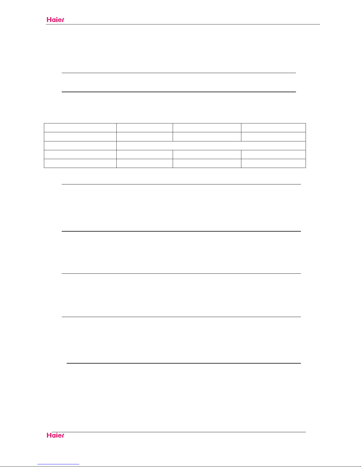
5.2.6.2 TD High Temperature Protections
As long as unit is on, the TD air discharge overheat protection feature will be activated, yet air
discharge sensor fault must be alarmed 4 minutes after compressor starts.
TD˄ć˅
Abnormal Shutdown
117
Rapid frequency drop˄1HZ/s˅
112
Slow frequency drop (1HZ/10s)
108
Invariable frequency
105
Frequency rise (1HZ/10s)
98
Frequency rise˄1HZ/1 s˅
When TD>117 for 20s continuouslyć ˈair discharge overheat protection will be activated and fault will
be reported to indoor unit.
It will not continue in other conditions.
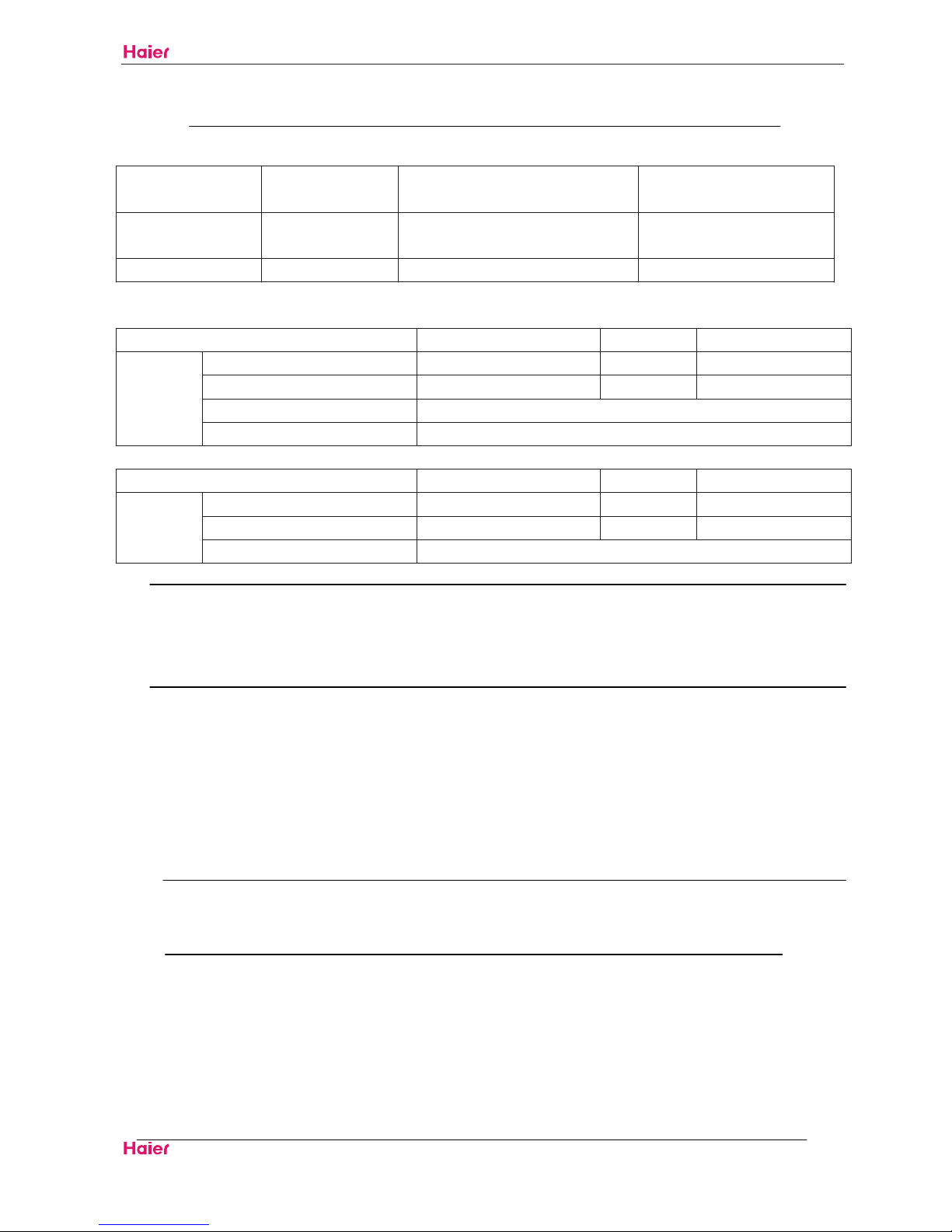
5.2.6.3 Indoor Heat Exchanger Anti-freeze Protection
Anti-freeze during cooling
9ć
1Hz/10sec 6ć
5 ć
0ć
When TC < 5ćˈcompressor frequency will drop at a speed of 1HZ/10s
When TC starts to riseˈand 6 TC 9ćˈcompressor frequency will remain unchanged.
When 9 < TC < 11 , frequć ency will rise nomal.
If TC 0ćˈfor 2 consecutive minutes, compressor will shutdown and outdoor fault lamp blinks. Fault
will not be reported to indoor unit.
When compressor shuts down for more than3 minutesˈand when TC>9ćˈcompressor will restart.
HSU09VHJ˄DB˅-SM
Funcitions and Control
Domestic Air Conditioner
24
5.2.6.4 Outdoor Temperature Limit
Cooling: When outdoor temperature is lower than 23 , cooling operation will start, compressor ć
frequency is limited to less than 50 HZ, outdoor wind speed is forced at level 1.
Heating: When outdoor temperature is higher than 18 , heating operation will start, compressor ć
frequency is limited to less than 53 HZ, outdoor wind speed is forced at level 1.
5.2.6.5 Special Features
1. Forced Cooling: When receiving indoor forced cooling signal, cooling operation will start in a
frequency signaled by indoor unit. Only air discharge temperature and over current protection features
are effective and other protection features are invalid.
2. Rated, Middle and Minimum Capacity Operation: When receiving indoor, rated, middle and
minimum capacity operation signal, outdoor unit will operate as per wind speed and frequency set by
EEPROM and all the protection features are effective.
5.2.6.6 Fault Display and Treatment
In case outdoor unit faults, the alarm indicator lamp will blink and blink frequency is 1HZˈTime interval
between blink cycles is 3s.
Alarm indicator lamp is off when there is no fault.
HSU09VHJ˄DB˅-SM
Funcitions and Control
Domestic Air Conditioner
25
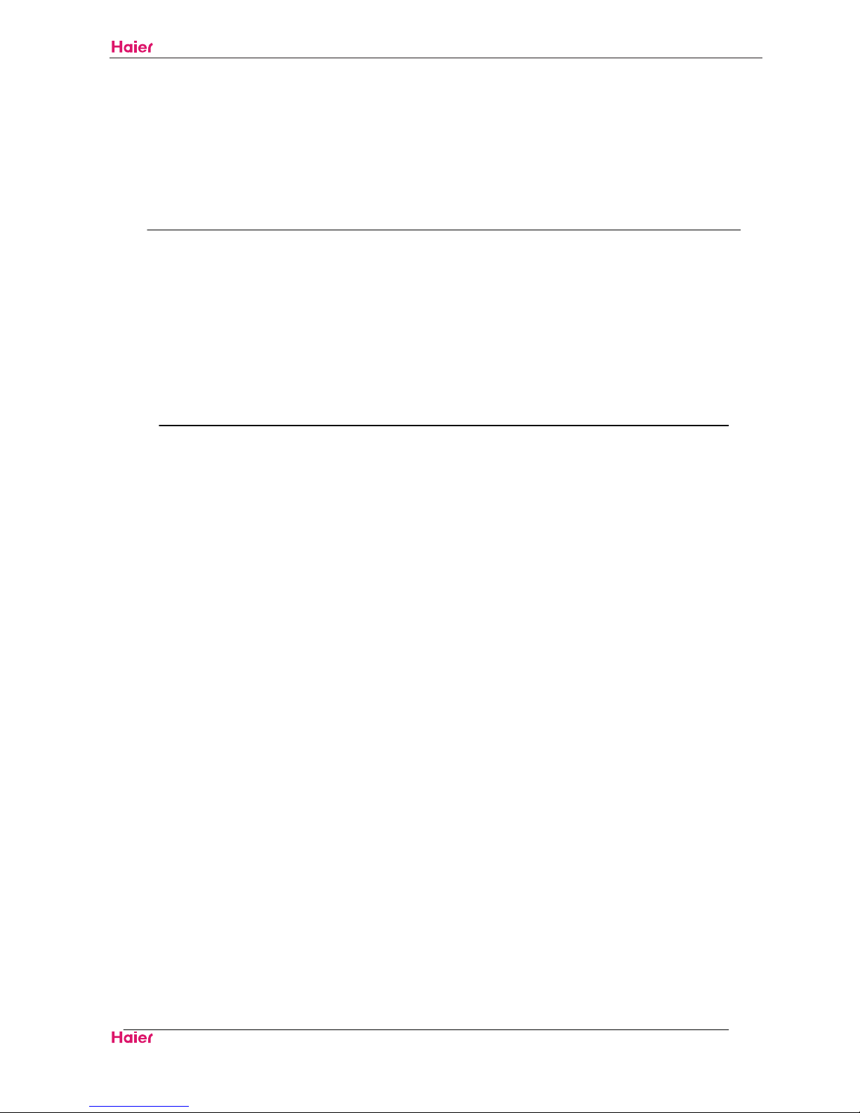
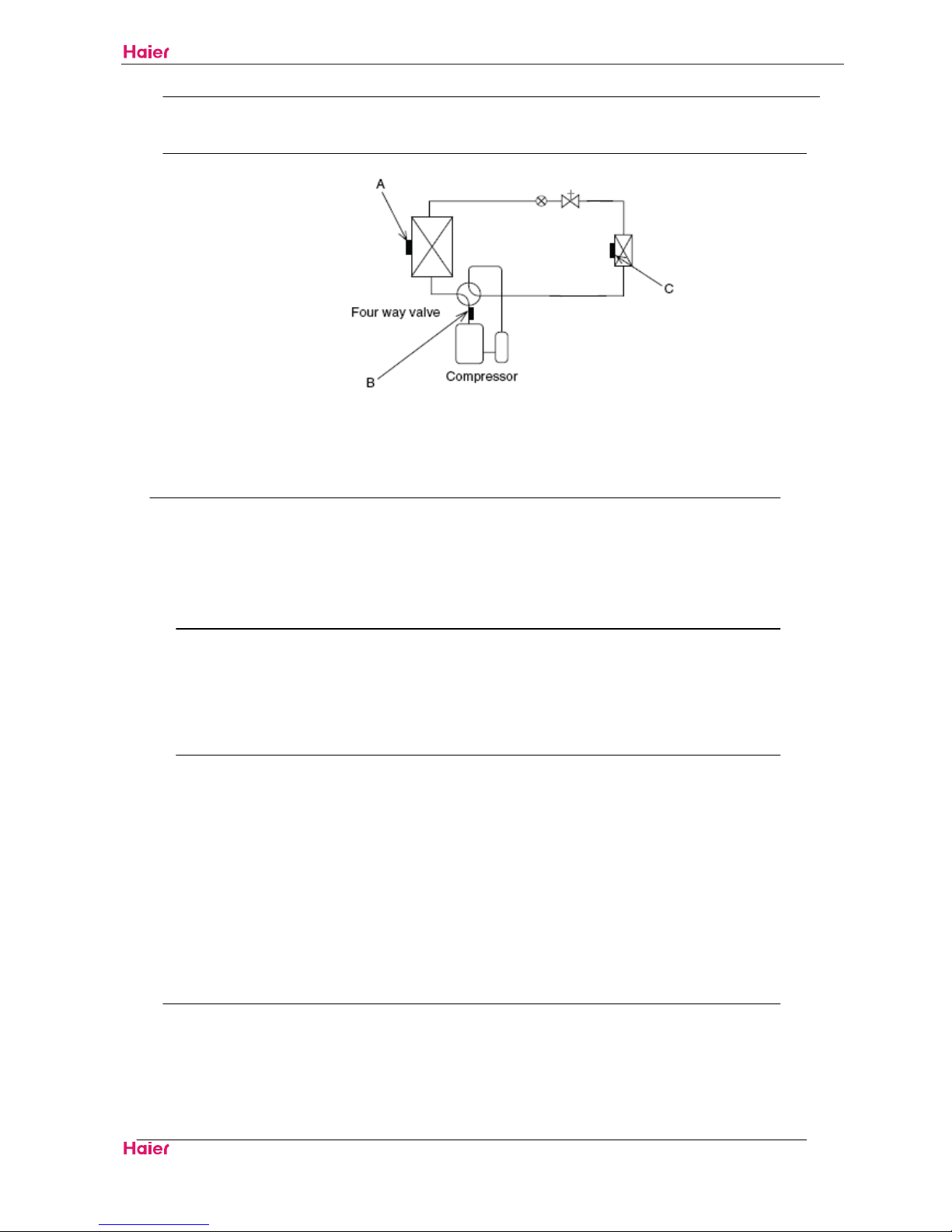
5.3 Function of Main Thermistor
Note: A:Outdoor suction temperature sensor
B: Exhaust temperature sensor
C: Indoor heat-exchange sensor
Outdoor Suction Temperature Sensor
The outdoor heat exchanger thermistor is used for controlling target discharge temperature.
The system sets a target discharge temperature according to the outdoor and indoor heat
exchanger temperature, and controls the electronic expansion valve opening so that the
target discharge temperature can be obtained.
Exhaust Temperature Sensor
The discharge pipe thermistor is used for controlling temperature of the discharge pipe.
If the temperature of discharge pipe (used in place of the inner temperature of the
compressor) rises abnormally, the operating frequency drops or the operation halts.
Indoor heat-exchange sensor
1.The indoor heat exchanger thermistor is used for controlling target discharge temperature.
The system sets a target discharge temperature according to the outdoor and indoor heat
exchanger temperature, and controls the electronic expansion valve opening so that the
target discharge temperature can be obtained.
2.The indoor heat exchanger thermistor is used for preventing freezing.During the cooling operation, if
the temperature drops abnormally, the operating frequency becomes lower, then the operation halts.
3.The indoor heat exchanger thermistor is used for anti-icing control.During the cooling operation, if
the heat exchanger temperature in the room where operation is halted becomes -1°C, it is assumed
as icing.
HSU09VHJ˄DB˅-SM
Funcitions and Control
Domestic Air Conditioner
26
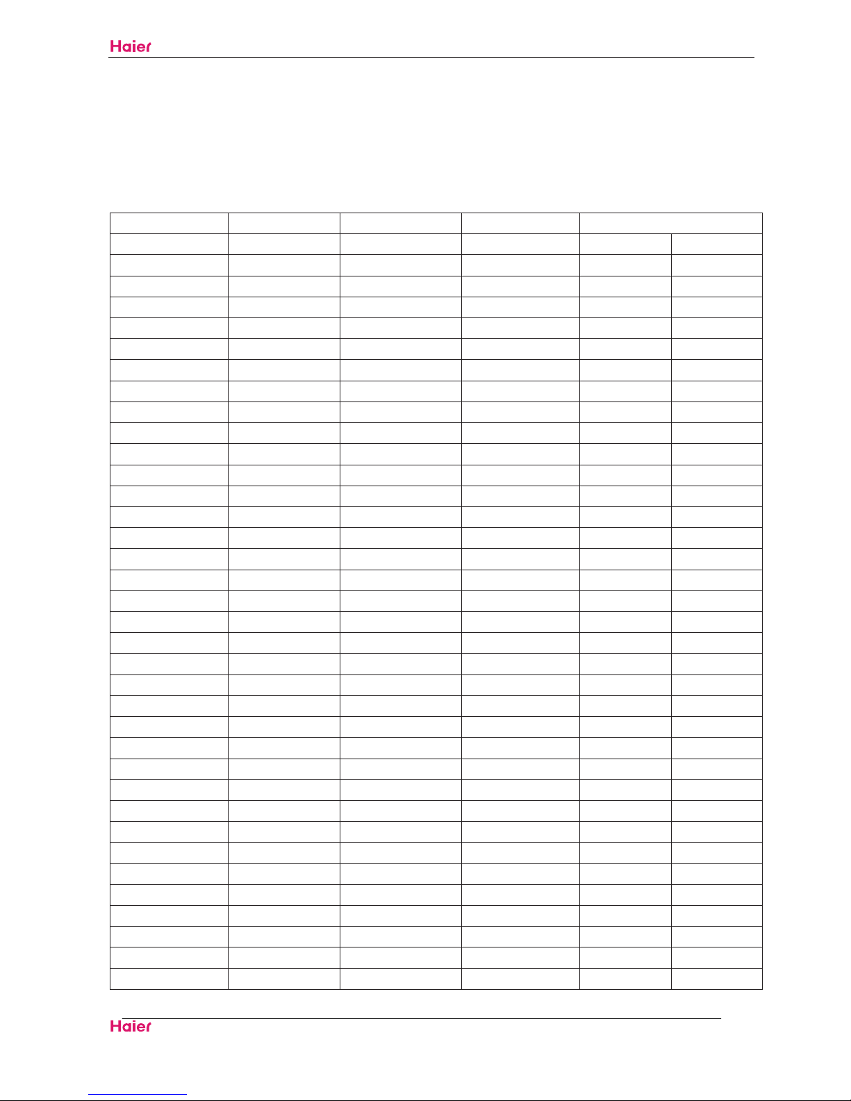
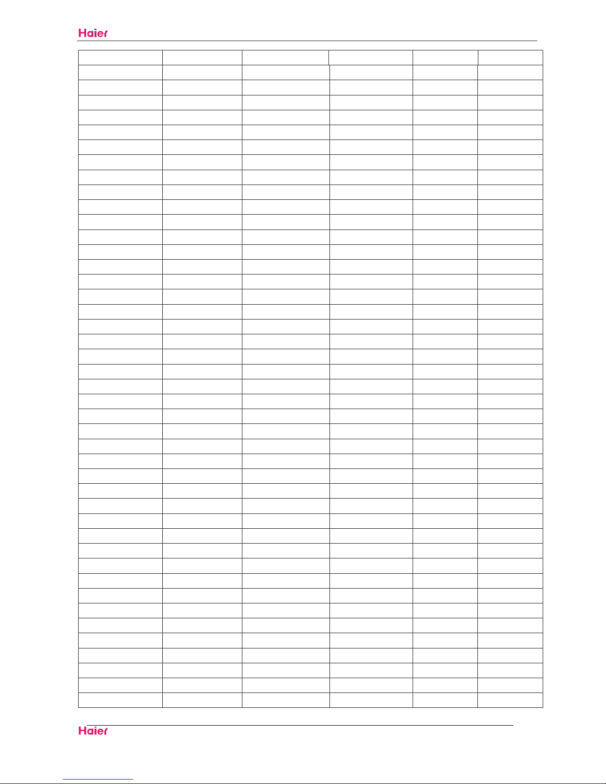
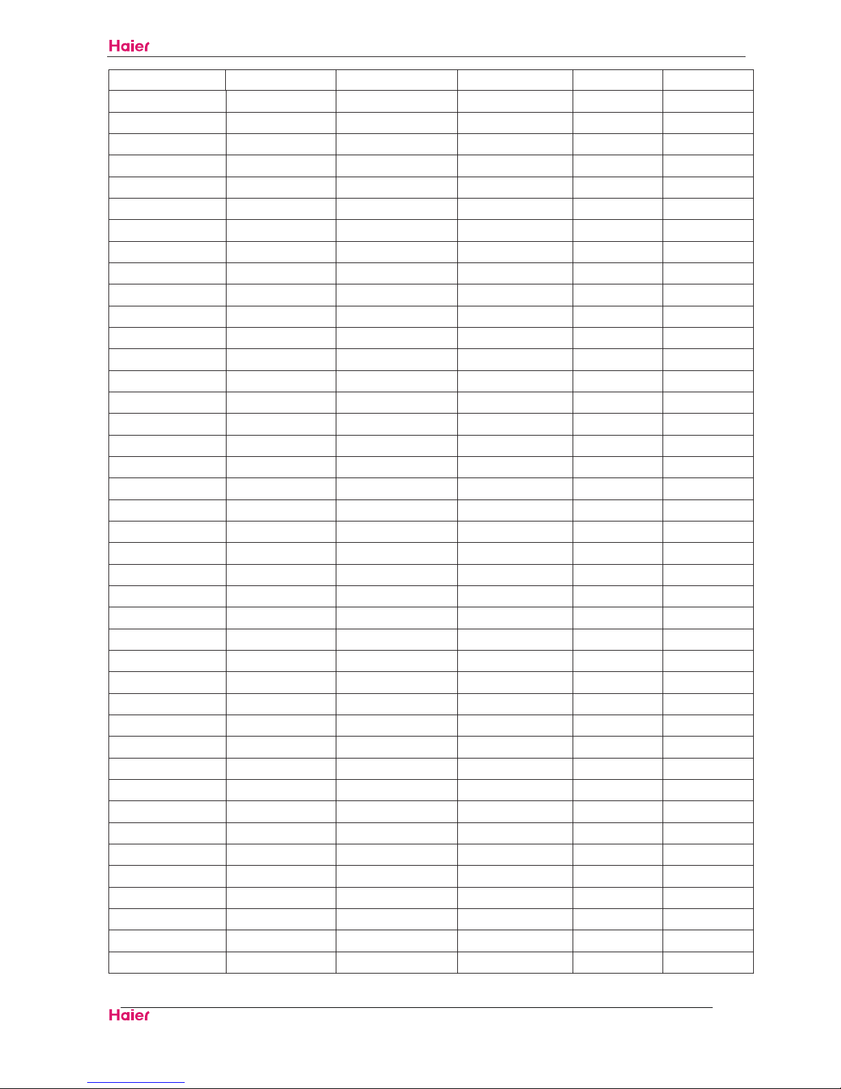
5.4 Value of Thermistor
5.4.1 intdoor Unit
Room sensor
R25 =23Kȍ±3.5%ć
B25 /50 =4200K±3%ćć
Temp.(ć)
Max.(Kȍ) Normal(Kȍ) Min.(Kȍ)
Tolerance(ć)
-30 568.8372 501.0746 440.8435 -1.97 1.75
-29 530.9600 468.6491 413.1441 -1.95 1.74
-28 495.8488 438.5314 387.3645 -1.93 1.72
-27 463.2850 410.5433 363.3602 -1.91 1.71
-26 433.0683 384.5212 340.9980 -1.90 1.70
-25 405.0156 360.3153 320.1558 -1.88 1.69
-24 378.9588 337.7879 300.7211 -1.86 1.67
-23 354.7440 316.8126 282.5905 -1.84 1.66
-22 332.2300 297.2732 265.6686 -1.82 1.64
-21 311.2873 279.0627 249.8676 -1.80 1.63
-20 291.7969 262.0831 235.1067 -1.78 1.62
-19 273.6494 246.2437 221.3111 -1.76 1.60
-18 256.7445 231.4612 208.4122 -1.74 1.59
-17 240.9897 217.6590 196.3462 -1.72 1.57
-16 226.3000 204.7662 185.0545 -1.70 1.56
-15 212.5973 192.7176 174.4829 -1.68 1.54
-14 199.8093 181.4531 164.5813 -1.66 1.53
-13 187.8698 170.9169 155.3033 -1.64 1.51
-12 176.7176 161.0578 146.6059 -1.62 1.49
-11 166.2961 151.8284 138.4495 -1.60 1.48
-10 156.5532 143.1847 130.7973 -1.58 1.46
-9 147.4409 135.0863 123.6153 -1.56 1.44
-8 138.9148 127.4956 116.8717 -1.53 1.43
-7 130.9337 120.3778 110.5374 -1.51 1.41
-6 123.4597 113.7009 104.5852 -1.49 1.39
-5 116.4577 107.4349 98.9897 -1.47 1.38
-4 109.8953 101.5523 93.7278 -1.45 1.36
-3 103.7422 96.0274 88.7774 -1.43 1.34
-2 97.9708 90.8365 84.1185 -1.40 1.32
-1 92.5551 85.9574 79.7322 -1.38 1.30
0 87.4712 81.3697 75.6011 -1.36 1.29
1 82.6970 77.0544 71.7088 -1.34 1.27
2 78.2118 72.9937 68.0402 -1.31 1.25
3 73.9966 69.1712 64.5813 -1.29 1.23
4 70.0335 65.5716 61.3188 -1.27 1.21
5 66.3062 62.1807 58.2405 -1.24 1.19
HSU09VHJ˄DB˅-SM
Funcitions and Control
Domestic Air Conditioner
27
6 62.7992 58.9853 55.3351 -1.22 1.17
7 59.4984 55.9729 52.5917 -1.20 1.15
8 56.3905 53.1320 50.0006 -1.17 1.13
9 53.4631 50.4521 47.5523 -1.15 1.11
10 50.7048 47.9230 45.2384 -1.13 1.09
11 48.1049 45.5355 43.0505 -1.10 1.07
12 45.6534 43.2808 40.9813 -1.08 1.04
13 43.3410 41.1509 39.0236 -1.05 1.02
14 41.1592 39.1381 37.1708 -1.03 1.00
15 39.0998 37.2355 35.4167 -1.00 0.98
16 37.1553 35.4363 33.7555 -0.98 0.96
17 35.3186 33.7344 32.1818 -0.95 0.94
18 33.5833 32.1240 30.6905 -0.93 0.91
19 31.9432 30.5997 29.2769 -0.90 0.89
20 30.3925 29.1565 27.9365 -0.88 0.87
21 28.9259 27.7895 26.6651 -0.85 0.84
22 27.5383 26.4944 25.4589 -0.83 0.82
23 26.2252 25.2670 24.3140 -0.80 0.80
24 24.9822 24.1034 23.2271 -0.78 0.77
25 23.8050 23.0000 22.1950 -0.78 0.77
26 22.7500 21.9499 21.1520 -0.78 0.78
27 21.7477 20.9536 20.1638 -0.82 0.81
28 20.7951 20.0081 19.2272 -0.86 0.85
29 19.8895 19.1104 18.3394 -0.89 0.88
30 19.0285 18.2581 17.4974 -0.93 0.92
31 18.2094 17.4484 16.6988 -0.97 0.95
32 17.4302 16.6792 15.9410 -1.00 0.99
33 16.6885 15.9480 15.2217 -1.04 1.02
34 15.9825 15.2530 14.5389 -1.08 1.06
35 15.3103 14.5920 13.8903 -1.12 1.09
36 14.6700 13.9632 13.2743 -1.16 1.13
37 14.0599 13.3650 12.6889 -1.20 1.16
38 13.4786 12.7957 12.1325 -1.23 1.20
39 12.9244 12.2537 11.6035 -1.27 1.24
40 12.3960 11.7375 11.1004 -1.31 1.27
41 11.8921 11.2459 10.6218 -1.35 1.31
42 11.4113 10.7775 10.1665 -1.39 1.34
43 10.9526 10.3311 9.7330 -1.43 1.38
44 10.5147 9.9056 9.3204 -1.48 1.42
45 10.0967 9.4999 8.9275 -1.52 1.45
46 9.6976 9.1130 8.5532 -1.56 1.49
47 9.3163 8.7439 8.1965 -1.60 1.53
48 8.9521 8.3916 7.8566 -1.64 1.57
49 8.6040 8.0554 7.5327 -1.68 1.60
HSU09VHJ˄DB˅-SM
Funcitions and Control
Domestic Air Conditioner
28
50 8.2713 7.7345 7.2237 -1.73 1.64
51 7.9531 7.4280 6.9291 -1.77 1.68
52 7.6489 7.1353 6.6480 -1.81 1.72
53 7.3580 6.8556 6.3797 -1.85 1.76
54 7.0796 6.5884 6.1237 -1.90 1.79
55 6.8131 6.3329 5.8793 -1.94 1.83
56 6.5581 6.0887 5.6459 -1.99 1.87
57 6.3140 5.8552 5.4230 -2.03 1.91
58 6.0802 5.6318 5.2100 -2.07 1.95
59 5.8563 5.4181 5.0065 -2.12 1.99
60 5.6417 5.2136 4.8120 -2.16 2.03
61 5.4361 5.0178 4.6260 -2.21 2.07
62 5.2391 4.8304 4.4481 -2.25 2.11
63 5.0502 4.6510 4.2780 -2.30 2.15
64 4.8691 4.4791 4.1153 -2.35 2.19
65 4.6954 4.3145 3.9596 -2.39 2.23
66 4.5287 4.1567 3.8105 -2.44 2.27
67 4.3689 4.0055 3.6678 -2.49 2.31
68 4.2154 3.8605 3.5312 -2.53 2.35
69 4.0682 3.7216 3.4004 -2.58 2.39
70 3.9268 3.5883 3.2750 -2.63 2.43
71 3.7910 3.4605 3.1549 -2.68 2.48
72 3.6606 3.3378 3.0398 -2.73 2.52
73 3.5353 3.2201 2.9294 -2.77 2.56
74 3.4150 3.1072 2.8237 -2.82 2.60
75 3.2993 2.9987 2.7222 -2.87 2.64
76 3.1881 2.8946 2.6249 -2.92 2.68
77 3.0812 2.7946 2.5316 -2.97 2.73
78 2.9785 2.6986 2.4420 -3.02 2.77
79 2.8796 2.6063 2.3560 -3.07 2.81
80 2.7845 2.5176 2.2735 -3.12 2.86
81 2.6931 2.4324 2.1943 -3.17 2.90
82 2.6050 2.3505 2.1182 -3.22 2.94
83 2.5203 2.2717 2.0451 -3.28 2.99
84 2.4388 2.1960 1.9749 -3.33 3.03
85 2.3602 2.1231 1.9075 -3.38 3.07
86 2.2846 2.0530 1.8426 -3.43 3.12
87 2.2118 1.9856 1.7803 -3.48 3.16
88 2.1416 1.9207 1.7204 -3.54 3.20
89 2.0740 1.8582 1.6628 -3.59 3.25
90 2.0089 1.7981 1.6074 -3.64 3.29
91 1.9461 1.7402 1.5541 -3.70 3.34
 Loading...