

Haier HSU-09RU03/R2, HSU-07RU03-R2, HSU-12RU03/R2, HSU-18RU03-R2 User Manual

Installation Manual of Room Air Conditioner
Read this manual before installation
Explain sufficiently the operating means to the user
according to this manual.
Necessary Tools for Installation
1.Driver
2.Hacksaw
3.Hole core drill
4.Spanner(17,19 and 26mm)
Accessory parts
No. Accessory parts
1
2
3
4
5
6
7
Remote controller
R-03 dry battery
Mounting plate
Drain hose
4X25
Screw
Plastic cap
Drain-elbow
Cushion
5.Torque wrench(17mm,22mm,26mm)
6.Pipe cutter
7.Flaring tool
8.Knife
Number
of
articles
1
2
Optional parts for piping
1
Mark
1
4
1
4
A
B
C
D
E
F
Heating insulating material
G
9.Nipper 12.Reamer
10.Gas leakage detector or
soap-and-water solution
11.Measuring tape
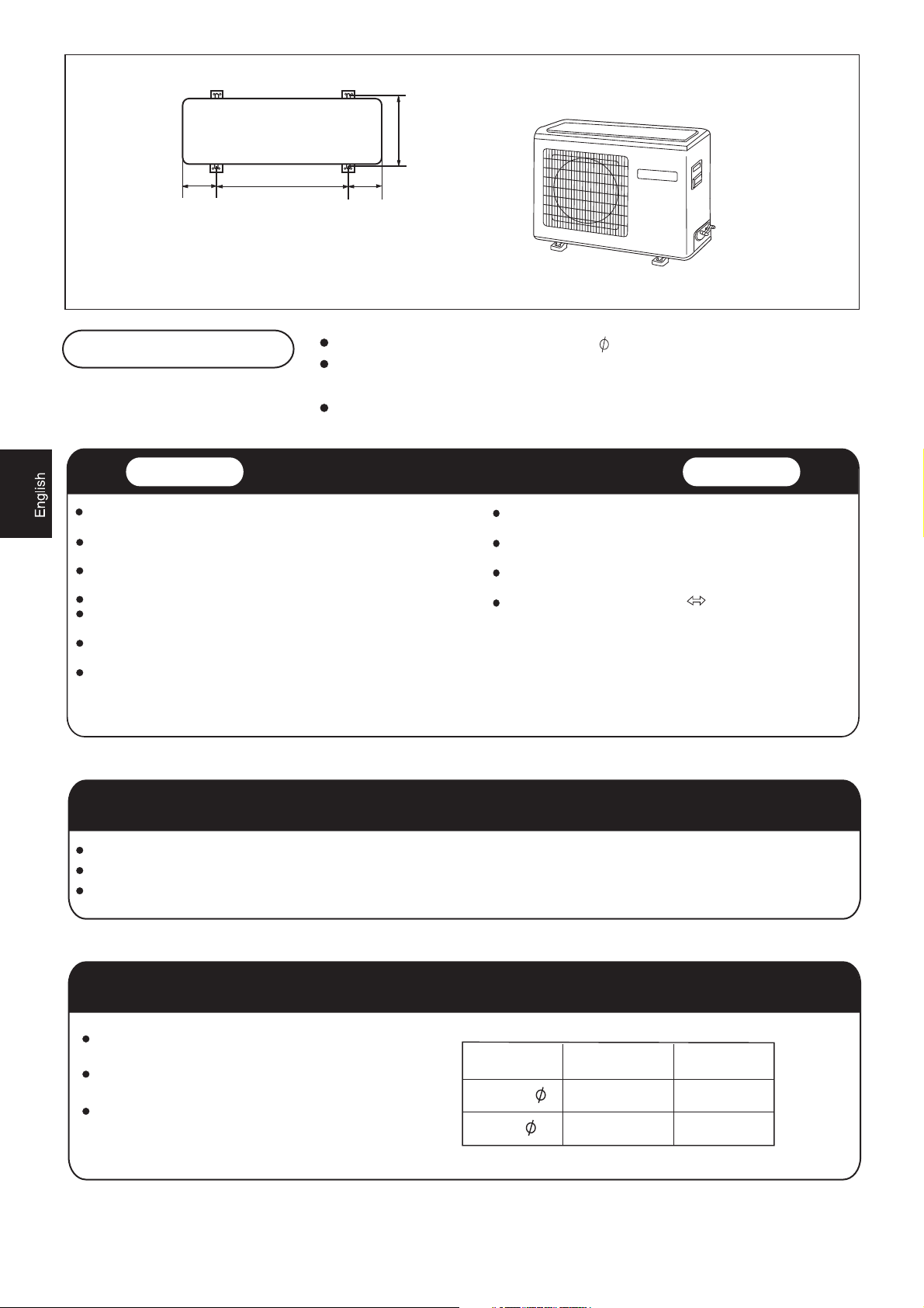
Drawing for the installation of indoor and outdoor units
The models adopt HFC free refrigerant R410A
more than 5cm
Attention must be paid to
the rising up of drain hose
Parts name
Non-adhesive tape
Adhesive tape
Saddle(L.S) with screws
Connecting electric cable
for indoor and outdoor
Drain hose
Piping hole cover
more than 10cm
G
more than 10cm
F
A
Arrangement of piping directions
Rear left
Below
Rear
right
Right
Left
The marks from to in the figure are the parts numbers.
The distance between the indoor unit and the floor should be
more than 2m.
more than 10cm
more than 60cm
A
C
more than 10cm
D
E
more than 15cm
G
500140 140
Floor fixing dimensions
of the outdoor unit
(Unit:mm)
256
Fixing of outdoor unit
Indoor Unit
Place, robust not causing vibration, where the body can be supported
sufficiently.
Place, not affected by heat or steam generated in the vicinity, where
inlet and outlet of the unit are not disturbed.
Place, possible to drain easily, where piping can be connected with the
outdoor unit.
Place, where cold air can be spread in a room entirely.
Place, nearby a power receptacle, with enough space around. (Refer
to drawings).
Place where the distance of more than lm from televisions, radios,
wireless apparatuses and fluorescent lamps can be left.
In the case of fixing the remote controller on a wall, place where the
indoor unit can receive signals when the fluorescent lamps in the room
are lightened.
Selection of Installation Place
Fix the unit to concrete or block with bolts( 10mm) and nuts firmly and horizontally.
When fitting the unit to wall surface, roof or rooftop, fix a supporter surely with nails
or wires in consideration of earthquake and strong wind.
If vibration may affect the house, fix the unit by attaching a vibration-proof mat.
Outdoor Unit
Place, which is less affected by rain or direct sunlight and is
sufficiently ventilated.
Place, possible to bear the unit, where vibration and noise are
not increased.
Place, where discharged wind and noise do not cause a
nuisance to the neighbors.
Place, where a distance marked is available as illustrated
in the above figure.
Power Source
Before inserting power plug into receptacle, check the voltage without fail. The power source is the same as the corresponding name plate.
Install an exclusive branch circuit of the power.
A receptacle shall be set up in a distance where the power cable can be reached. Do not extend the cable by cutting it.
Selection of pipe
To this unit, both liquid and gas pipes shall be insulated
as they become Iow temperature in operation.
Use optional parts for piping set or pipes covered with
equivalent insulation material.
The thickness of the pipe must be 0.8 mm at least.
Liquid pipe( )
Gas pipe( )
2
For 07,09,12 For 18
6.35mm(1/4")
9.52mm(3/8")
6.35mm(1/4")
12.7mm(1/2")
Indoor unit
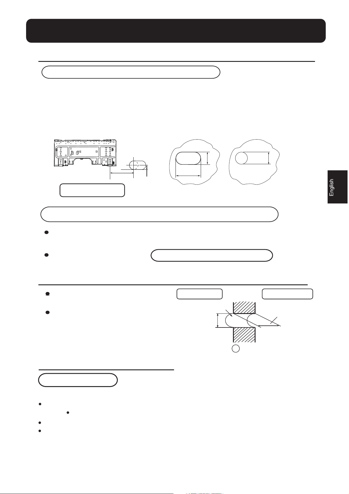
1.Fitting of the Mounting Plate and Positioning of the wall Hole
When the mounting plate is first fixed
1.Carry out, based on the neighboring pillars or lintels, the mounting plate must be fixed
horizontally. Otherwise,condensed water may overflow the water container.
Then temporarily fasten the plate with one steel nail.
2. Make sure once more the proper level of the plate, by hanging a thread with a weight from
the central top of the plate, then fasten securely the plate with the attachment steel nail.
3. Find the wall hole location A using a measuring tape
70mm
Fit the level line
A=80mm
70mm
35
120mm
For the units with
fresh air function
When the mounting plate is fixed side bar and lintel
Fix to side bar and lintel a mounting bar, Which is separately sold, and then fasten
the plate to the fixed mounting bar.
Refer to the previous article, " When the mounting plate is first fixed ", for the
position of wall hole.
2.Making a Hole on the Wall and Fitting the Piping Hole Cover
Make a hole of 70 mm in diameter,
slightly descending to outside the wall.
Install piping hole cover and seal it
off with putty after installation
Indoor side
Wall hole
70mm
Outdoor side
Thickness
of wall
G
(Section of wall hole)
Piping hole pipe
3.Installation of the Indoor Unit
Drawing of pipe
[ Rear piping ]
Draw pipes and the drain hose, then fasten them with the adhesive tape
[ Left Left-rear piping ]
In case of left side piping, cut away, with a nipper, the lid for left piping.
In case of left-rear piping, bend the pipes according to the piping direction to the mark of hole for left-rear
piping which is marked on heat insulation materials.
3

Indoor unit
1. Insert the drain hose into the dent of heat insulation materials of indoor unit.
2. Insert the indoor/outdoor electric cable from backside of indoor unit, and pull it out on the front side, then
connect them.
3. Coat the flaring seal face with refrigerant oil and connect pipes.
Cover the connection part with heat insulation materials closely, and make sure fixing with adhesive tape
Heat insulation
material
signal wire
Piping
Lid for right piping
Lid for under piping
Fix with adhesive tape
Indoor/outdoor electric cable and drain hose must be bound with refrigerant piping by protecting tape.
Drain hose
Lid for left piping
Drain hose
Indoor/outdoor
electric cable
Change-for-fresh-air tube
[Other direction piping]
Cut away, with a nipper, the lid for piping according to the piping direction and then bend the pipe according
to the position of wall hole. When bending, be careful not to crash pipes.
Connect beforehand the indoor/outdoor electric cable, and then pull out the connected to the heat insulation
of connecting part specially.
Fixing the indoor unit body
Hang surely the unit body onto the upper notches of the
mounting plate. Move the body from side to side to verify
its secure fixing.
In order to fix the body onto the mounting plate,hold up
the body aslant from the underside and then put it down
perpendicularly.
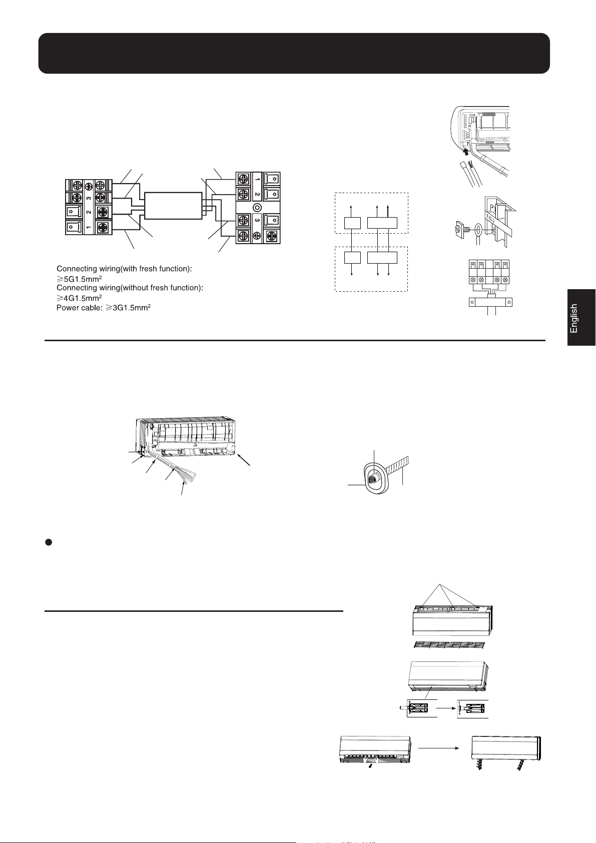
4.Connecting the indoor/outdoor Electric Cable
Removing the wiring cover
Remove terminal cover at right bottom corner of indoor unit, then
take off wiring cover by removing its screws.
When connecting the cable after installing the indoor unit
1. Insert from outside the room cable into left side of the wall hole, in which
the pipe has already existed.
2. Pull out the cable on the front side, and connect the cable making a loop.
When connecting the cable before installing the indoor unit
Insert the cable from the back side of the unit, then pull it out on the front side.
Loosen the screws and insert the cable ends fully into terminal block, then tighten the screws.
Pull the cable slightly to make sure the cables have been properly inserted and tightened.
After the cable connection, never fail to fasten the connected cable with the wiring cover.
Note: When connecting the cable, confirm the terminal number of indoor and outdoor units carefully. If wiring
is not correct, proper operation can not be carried out and will cause defect.
4
Indoor unit
1. If the supply cord is damaged, it must be replaced by the manufacturer or its service agent or a similar
qualified person. The type of connecting wire is H05RN-F or H07RN-F.
2. If the fuse on PC board is broken please change it with the type of T. 3.15A/250V.
3. The wiring method should be in line with the local wiring standard.
4. After installation, the power plug should be easily reached.
BLK
WHT
For the units with
fresh air function
To indoor unit
YEL/GRN
RED
Indoor unit
BLK
WHT
RED
YEL/GRN
Outdoor unit
To outdoor fresh air motor
The connecting method of
fresh air box signal wire
5.Installation instruction on the indoor part of the fresh air device(optional)
Two ways for the installation of indoor part, as illustrated:
Way One : When
on the two sides of the frame,and then fix it at the pipe exit of the frame
Way Two :
When installing the side outlet pipe,connect the fresh tube and the outlet joint ,and then fix it on the left side
or right side of the frame.Outlet pipe is connected with the pipe hole cover by the pipe lid.
Lid for right piping
Fix with adhesive tape
Change-for-fresh-air tube
the pipes go from the back of the indoor unit, you can connect the fresh air tube with the outlet joint
Outlet joint
Outlet joint
Lid for left piping
Guard ring
Drain hose
Installation way One Installation way Two
(in guard ring)
Fresh air tube
See the Installation from the fresh air sets for the installation of outdoor unit.
claw of the clip
6.Easily-demount cleaning of indoor unit
1.Top inlet can be taken down
Open the inlet grille, press the claw of the clip on the unit,then
take down the top inlet.(according to figure 1)
2.Vertical flap can be taken down
Overturn the vertical flap, press the claw of the clip ,then take
down vertical flap.(according to figure 2)
3.Horizontal louvers can be taken down
After taking down vertical flap.Horizontal louvers are appeared,draw
the middle louver,and take down the horizontal louvers .
(according to figure 3)
5
Daff
Figure 3
Figure 1
Figure 2

Outdoor unit
1.Installation of Outdoor Unit
Install according to
Drawing for the installation of indoor and outdoor units
2.Connection of pipes
To bend a pipe, give the roundness as large as possible not to crush the pipe ,and the bending radius
should be 30 to 40 mm or longer.
Connecting the pipe of gas side first makes working easier.
The connection pipe is specialized for R410A.
The max vertical distance between the indoor unit and the outdoor unit is 5 m.
Half union
Spanner
Flare nut
Torque wrench
Forced fastening without careful centering
may damage the threads and cause a
leakage of gas.
Pipe Diameter ( )
Liquid side 6.35mm(1/4")
Gas side 9.52mm(3/8")
Gas side 12.7mm(1/2")
Fastening torque
18N.m
40N.m
55N.m
Be careful that matters, such as wastes of sands, etc. shall not enter the pipe.
The standard pipe length is 5m. If it is over 5m, the function of the unit will be affected. If the pipe has
to be lengthened, the refrigerant should be charged, according to 20 g/m. But the charge of refrigerant
must be conducted by professional air conditioner engineer. Before adding additional refrigerant,
perform air purging from the refrigerant pipes and indoor unit using a vacuum pump,then charge
additional refrigerant.
3.Connection
Use the same method on indoor unit. Loosen the screws on terminal block and insert the plugs fully into
terminal block, then tighten the screws.
Insert the cable according to terminal number in the same manner as the indoor unit.
If wiring is not correct, proper operation can not be carried out and controller may be damaged.
Fix the cable with a clamp.
4.Attaching Drain-Elbow
If the drain-elbow is used, please attach it as
figure. (Note: Only for heat pump unit.)
6

Outdoor unit
5.Purging Method:To use vacuum pump
1
Detach the service port's cap of 3-way valve, the
valve rod's cap for 2-way valve and 3-way's, connect
the service port into the projection of charge hose
(Iow) for gaugemanifold. Then connect the projection
of charge hose (center) for gaugemanifold into
vacuum pump.
2
Open the handle at Iow in gaugemanifold, operate
vacuum pump. If the scale-moves of gause (Iow)
reach vacuum condition in a moment, check again.
3
Vacuumize for over 15min. And check the level gauge
which should read -0.1 MPa (-76 cm Hg) at Iow
pressure side. After the completion of vacuumizing,
close the handle 'Lo' in gaugemanifold and stop the
operation of the vacuum pump.
Check the condition of the scale and hold it for 1-2min.
If the scale-moves back in spite of tightening, make
flaring work again, the return to the beginning of .
1
3
2-way valve
Tube(for R410A)
Open
Close
Liquid Side Gas Side
6.35mm(1/4") 9.52mm(3/8")
12.7mm(1/2")
3-way valve
Gaugemanifold(for R410A)
Vacuum pump(for R410A)
Anti countercurrent joint
4
Open the valve rod for the 2-way valve to an angle of
anticlockwise 90 degrees.
After 6 seconds, close the 2-way valve and make
the inspection of gas leakage.
5
No gas leakage?
6
Detach the charge hose from the service port, open
2-way valve and 3-way. Turn the valve rod anticlockwise
until hitting lightly.
7
To prevent the gas leakage, turn the service port's
cap, the valve rod's cap for 2-way valve and 3-way's
a little more than the point where the torque increases
suddenly.
8
After attaching the each caps, check the gas leakage
around the caps.
In case of gas leakage, tighten
parts of pipe connection. If
leakage stops, then proceed
steps.
Open
3-way valve
Service port
for 6 sec.
3-way valve
3-way valve
Valve rod cap
Valve rod cap
2-way valve
If it does not stop gas leakage, discharge
whole refrigerants from the service port.
After flaring work again and vacuumize,
6
fill up prescribed refrigerant from the gas
cylinder.
2-way valve
2-way valve
Service port cap
CAUTION:
1.If the refrigerant of the air conditioner leaks, it is necessary to
discharge all the refrigerant. Vacuumize first, then charge the liquid
refrigerant into air conditioner according to the amount marked on
the name plate.
2.Please do not let other cooling medium, except specified one (R410A),
or air enter into the cooling circulation system. Otherwise, there will be
abnormal high pressure in the system to make it crack and lead to
personal injuries.
7

1.Power Source Installation
The power source must be exclusively used for air conditioner. (Over I0A)
In the case of installing an air conditioner in a moist place, please install an
earth leakage breaker.
For installation in other places, use a circuit breaker as far as possible.
2.Cutting and Flaring Work of Piping
Pipe cutting is carried out with a pipe cutter and burs must be removed.
After inserting the flare nut, flaring work is carried out.
A
Flare tool for R410A
Clutch-type
A
0~0.5mm 1.0~1.5mm 1.5~2.0mm
clutch-type(Rigid-type)
1.Cut pipe
Flare tooling die
2.Remove burs
3.Insert the flare nut
Correct
Incorrect
4.Flare pipe
Lean Damage of flare Crack Partial Too outside
3.On Drainage
Please install the drain hose so as to be downward slope without fail.
Please don't do the drainage as shown below.
Conventional flare tool
Wing-nut type (Imperial-type)
Less than 5cm
It becomes high
midway.
The end is immersed
in water.
It waves. The gap with the ground
is too small
There is the bad smell
from a ditch
Please pour water in the drain pan of the indoor unit, and confirm that drainage is
carried out surely to outdoor.
In case that the attached drain hose is in a room, please apply heat insulation
to it without fail.
Check for Installation and Test Run
Please kindly explain to our customers how to operate through the instruction manual.
Check Items for Test Run
Gas leak from pipe connecting?
Heat insulation of pipe connecting?
Are the connecting wirings of
indoor and outdoor firmly inserted
to the terminal block?
Is the connecting wiring of indoor
and outdoor firmly fixed?
Put check mark in boxes
Is drainage securely carried out?
Is the earth line securely
connected?
Is the indoor unit securely fixed?
Is power source voltage abided
by the code?
Is there any noise?
8
Is the lamp normally lighting?
Are cooling and heating (when
in heat pump) performed normally?
Is the operation of room temperature
regulator normal?

Manual de instalación
• Antes de proceder a la instalación lean el presente manual.
• Explique al usuario final el funcionamiento del aparato de acuerdo con lo que figura en el presente manual.
Herramientas necesarias para la instalación
1. Destornillador
2. Sierra
3. Taladro
4. Llave Allen (17, 19 y 26mm)
5. Llave inglesa (17, 22 y 26mm)
6. Cortatubos
7. Empalmador
8. Cuchillo
9. Pinzas
10.
Detector de escapes o espuma de jabón
11. Metro
12. Rascador
Esquema para la instalación de las unidades interna y externa
N. Ctd.Accesorios
1
Mando a distancia
2
Pilas
3
Galga de montaje
4
tubo de evacuación del agua
de condensación
5
6
7
4X25
Tornillo
porta-goma
cojinete
taco
1
más de
2
10cm
1
1
4
1
4
más de 5 cm
Prestar atención a la
pendiente del tubo de
evacuación del agua
de condensación
G
más de
10cm
A
F
A
B
C
D
E
F
G
Preinstalación para la salida de las
tuberías
izquierda
Cinta no adhesiva
Cinta adhesiva
Abrazadera para tuberías con tornillos
Cable de conexión UI/UE
Tubo de evacuación del agua
de condensación
Material termoaislante
Cubre-orificio
posterior
izquierda
posterior
derecha
derecha
inferior
más de
10cm
más de
60cm
más de
10cm
más de
C
D
E
15cm
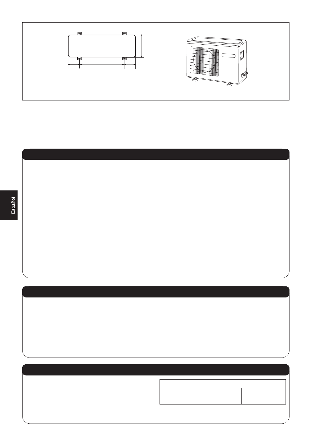
• Este modelo usa el gas refrigerante ecológico R410A.
• La distancia entre la unidad interna y el suelo debe ser superior a los 2 m y no deben existir obstáculos debajo (p. ej. armarios).
• Le recordamos que la instalación de los aparatos debe realizarse de acuerdo con las normas para permitir el acceso directo
a los mismos para su mantenimiento. Queda excluido de la cobertura de la garantía el uso eventual de andamiajes, grúas,
etc. para realizar el mantenimiento.
9
652
500140 140
Medidas para la fijación al suelo
de la unidad externa (mm)
Fijación de la unidad externa
• Fije sólidamente la unidad externa a una base de cemento con pernos (Ø10 mm) y tuercas, de modo horizontal.
• Si la unidad externa está montada en una pared o en un techo, fije las abrazaderas de soporte sólidamente, de modo que
puedan resistir a fuertes vientos o terremotos.
• Para evitar que las vibraciones se transmitan al edificio, fije un cojinete antivibración a la unidad externa.
Elección del lugar de instalación
Unidad interna
• Colocación resistente y que no produce vibraciones, don-
de el cuerpo del aparato esté suficientemente sostenido.
• Colocación no expuesta a calor o vapor generado cerca,
Colocación en la que la toma y salida del aire no estén
obstruidas.
• Colocación en la que sea fácil conectar las tuberías a la
unidad externa.
• Colocación en la que el aire frío se pueda difundir fácil-
mente en todo el local.
• Colocación cerca de una toma de corriente, con suficien-
te espacio alrededor (véase dibujos).
• Colocación en la que haya una distancia superior a 1 m de
televisores, radio, aparatos sin hilos y lámparas fluorescentes.
• En caso de que se fije el mando a distancia a la pared, la
posición debe ser tal que permita a la unidad interna recibir las señales cuando las lámparas fluorescentes de la estancia estén encendidas.
Unidad externa
• Colocación expuesta lo menos posible a la lluvia o a la luz
solar directa y suficientemente ventilada.
• Colocación capaz de soportar al aparato, y en la que no
se amplifiquen ni el ruido ni las vibraciones.
• Colocación en la que el aire y el ruido producidos por el climatizador no ocasionen molestias a los vecinos.
• Respetar los espacios necesarios para la instalación indicados en el dibujo de la página anterior.
Alimentación eléctrica
• Antes de introducir el enchufe de alimentación en la toma de la corriente eléctrica, se aconseja controlar el voltaje.La tensión de alimentación debe corresponder a cuanto se indica en la placa.
• Instalar un circuito de alimentación especialmente dedicado (superior a los 10 A).
• En caso de colocación en un lugar muy húmedo, instale un detector de dispersión eléctrica.
• En todos los casos, instale un disyuntor de corriente.
• La toma de corriente deberá hallarse a una distancia tal que pueda llegar el cable de alimentación eléctrica. Evite alargos.
Elección de las tuberías
• Aísle térmicamente tanto los tubos del líquido como los del
gas, ya que durante el funcionamiento se alcanzan temperaturas muy bajas.
• El grosor de los tubos debe ser como mínimo de 0,8 mm.
Diámetro tuberías
Tubo líquido Ø 6,35 mm (1/4”) Ø 6,35 mm (1/4”)
Tubo gas Ø 9,52 mm (3/8”) Ø 12,7 mm (1/2”)
10
mod. 7-9-12 mod. 18

Unidad interna
1. FIJACIÓN DE LA GALGA DE MONTAJE
1) Realice la puesta a nivel para la galga que debe fijarse a la pared, basándose en columnas o arquitraves próximos, fije
temporalmente la galga a la pared con un clavo de acero. La galga debe montarse horizontalmente, en caso contrario, una
vez instalada la unidad interna, el agua de condensación puede salirse de la bandeja de recogida del agua de condensación.
2) Compruebe una vez más que la galga esté bien nivelada mediante una plomada desde el centro superior de la galga,
entonces fíjela sólidamente con el clavo de acero.
3) Establezca el punto del orificio A en la pared usando un metro.
mm07
120mm
53
A=80mm
Sólo para los modelos
con la función “cambio de aire”
4) Como alternativa se puede fijar en la pared una barra de montaje horizontal, a la que aplicar la galga de montaje.
2. SITUACIÓN DEL ORIFICIO EN LA PARED
1) Realice un orificio de 70 mm de diámetro, ligeramente inclinado hacia la parte exterior de la pared.
2) Aplique el cubre-orificio de las tuberías y séllelo con mástique después de la aplicación.
Lado interno
Lado externo
mm07
Orificio en la pared
Grosor de la pared
Ø70mm
11
 Loading...