

Haier Hr48c1var Owner's Manual

HAIER
COMMERCIAL
AIR CONDITIONER
Service Manual
Part # AC-8888-108
HAIER TRADING COMPANY, LLC
www.haieramerica.com
1

Commercial Air Conditioning
SERVICE MANUAL
●Features
High efficiency design
Models
HR18C1VAR HR24C1VAR
HR30C1VAR HR36C1VAR
HR42C1VAR HR48C1VAR
HR60C1VAR
Hermetic compressor design
Haier Hi-Efficiency fin and copper tube design
Compact design of outdoor unit
Convenient for installation and maintenance
Heat pump, 12SEER
Manual code: SYJS----AM-----003-04---Rev.2
Edition: 2005-03-22

Commercial Air Conditioner Model: heat pump, 12SEER UNITS
CONTENTS
1. DESCRIPTION OF PRODUCTS & FEARURES……………………..3
2.PHYSICAL AND ELECTRICAL SPECIFICATIONS………………..…5
3.SAFETY PRECAUTION…………………………………………….……7
4.SYSTEM COMPONENTS AND FUNCTIONS …………………………7
5.ELECTRICAL CONTROL DEVICES…………………………….……..9
6.APPLICATION…………………..……………………………………..….10
7.INSTALLATION INSTRUCTIONS………………………....……………12
8.MAINTENANCE INSTRUCTIONS………………………………..……..29
9.SERVICE AND TROUBLESHOOTING ……………………...…………30
10.WIRING DIAGRAMS……………………………….……………………41
11. EXPLOSIVE DIAGRAM AND SPARE PARTS LIST ……………42
2

Commercial Air Conditioner Model: heat pump, 12SEER UNITS
1. DESCRIPTION OF PRODUCTS & FEARURES
1.1 Air conditioner
This manual discusses “split” central air conditioning ,indoor coils, .”Split” refers to the physical location
of the major air conditioning components that are not in the same box ,as in a “packaged” system.
10 SEER(“Seasonal Energy Efficiency Ratio”), families of split system air conditioning are
manufactured to rigid standards of quality and performance. They meet or exceed the standards
imposed by efficiency legislated and therefore represent both good value today and for years to come.
The current families of the air conditioning now use scroll and reciprocating compressors. This gives
the air conditioning a much more durable compressor needing less external protection while
increasing the unit efficiency in cooling mode.
1.2 NOMENCLATURE FOR MODEL NUMBE
Example
.
H C 24 A 1 V A R
Nominal
Haier System type
Brand
symb
ol :H:
Haier
Table 1-1
C: Air
Conditioner;
R: Heat
Pump
capacity in
(1000) Btuh
24:
24000BTU/h;
60:
60000BTU/h
SEER
designation
A:10SEER;
B:11SEER;
C:12SEER;
D:13SEER
E:14SEER;
F:15SEER;
G:16SEER;
H:17SEER
I:18SEER
Design
series
1:1st
Generatio
2:2nd
Generatio
n;
n
Electric Designation Body style
Y:575V-3Ph-60Hz;
V:208/230V-1Ph-60
Hz;
C:208/230V-3Ph-60
Hz;
D:460V-3Ph-60Hz;
A:115V,1 Ph,60Hz
A:
standard
style
Reserved
1.3 ENGINEERING FEATURES:
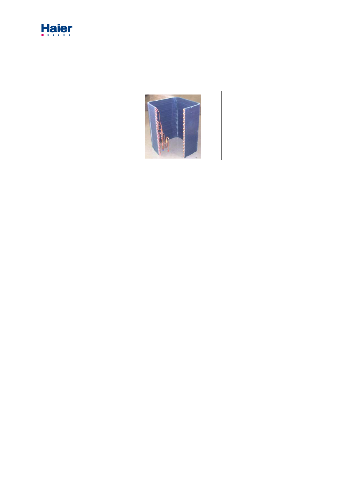
COPPER TUBE/ALUMINUM FIN COILS Both indoor and outdoor coils are designed to optimize heat
transfer, minimize size and cost, and increase durability and reliability.
Fig.1-1
3

Commercial Air Conditioner Model: heat pump, 12SEER UNITS
CABINETS-Constructed of powder painted and galvanized steel providing protection to the outdoor
unit and a durable finish.
Fig.1-2
SERVICE VALVES-Facilitates unit servicing and provides a reliable and safe access to measure unit
pressures .
Fig.1-3
FLOWCHECK DISTRIBUTORS-Outdoor units use the Flowcheck Distributor to act as an open check
valve in the cooling mode. BASE PAN-.
This deep-drawn and sturdy base keeps the bottom of the coil
out of harms way. The base has weep holes to allow the water from rain to flow away from the unit.
Fig.1-4
ACCESSORIES
LOW AMBIENT CONTROL- This allows low temperature operation in the cooling cycle down to 0
℉,outdoor temperature .This control should be installed in units that operate in cooling in outdoor
ambient temperatures below 65℉, and is recommended for all commercial applications.
START COMPONENTS – Offer additional starting torque covering a wide range of voltage and
pressure variations .Usually required on reciprocating compressors with flowcheck piston metering .
4

Commercial Air Conditioner Model: heat pump, 12SEER UNITS
2.Physical and Electrical Specifications
12 SEER
Model Number
Comments 1.5-Ton Outdoor HP 2-Ton Outdoor HP 2.5-Ton Outdoor HP 3-Ton Outdoor HP 3.5-Ton Outdoor HP 4-Ton Outdoor HP 5-Ton Outdoor HP
Model Status New Model New Model New Model New Model New Model New Model New Model
Performance
with Matching Indoor Unit
Cooling Capacity (Btu/h)
Net Sensible Capacity (Btu/h)
Net Latent Capacity (Btu/h) 5,040 6,720 8,400 9,800 11,760 13,020 15,680
SEER 12.0 12.0 12.0 12.0 12.0 12.0 12.0
Total Input Watts (Cooling) 1,800 2,400 3,099 3,357 4300 4609 5560
Heating Capacity (Btu/h) (8.3℃)
Heating COP (8.3℃)
Heating HSPF 7.3 7.3 7.3 7.3 7.3 7.3 7.3
Total Input Watts (Heating) 1550.0 2000.0 2660.0 2970.0 3670.0 4000.0 5230.0
Outdoor Rated Airflow (CFM) 1950 2200 2700 2700 2700 2900 3200
Electrica
Voltage - Phase - Frequency (Hz) 208/230 - 1 - 60 208/230 - 1 - 60 208/230 - 1 - 60 208/230 - 1 - 60 208/230 - 1 - 60 208/230 - 1 - 60 208/230 - 1 - 60
Minimum Circuit Amps 9.4 13.4 16.1 17.7 21.2 34.7 38.6
Maximum Fuse Size(A) 15.0 20.0 25.0 30.0 35.0 60 60
Compresso
Type / Maker Reciprocating Reciprocating Reciprocating Reciprocating Reciprocating Scroll Scroll
Model Number H20J173ABCA H20J223ABCA H20J293ABCA H20J323ABCA H20J403ABCA H23R483ABCA H20R583ABCA
RLA (Rated Load Amps) 6.8 9.6 11.7 13.0 15.8 26.6 28.9
LRA (Locked Rotor Amps) 48.0 60.0 73 85.0 90 155 165
Input Watts 1550 2030 2550 2810 3510 4185 5080
Internal Overload Protection Yes Yes Yes Yes Yes Yes Yes
Crankcase Heater Yes Yes Yes Yes Yes Yes Yes
Fan Motor
RLA (Rated Load Amps) 0.86 1.4 1.43 1.43 1.43 1.4 2.5
Rated House Power (hp) 1/8 1/5 1/3 1/3 1/3 1/3 1/2
Nominal RPM 1000 1075 1075 1075 1075 1075 1075
Input Watts 90.0 180.0 300 300 300 350 500
Fan
Diameter (In) 18.0 18.0 22 22 22 22 24
No. of Blade 3 3 33333
Fan Material Zinc-Coated Steel Zinc-Coated Steel ALUMINIUM ALUMINIUM ALUMINIUM ALUMINIUM ALUMINIUM
Condenser coi
Number or Rows 1 1 1 1 222
Tube spacings (V x H) (In) 1 x 0.85 1 x 0.85 1 x 0.85 1 x 0.85 1 x 0.85 1 x 0.85 1 x 0.85
Fins per Inch - FPI 21 21 21 21 16 16 17
Fin Type Enhanced fins Enhanced fins Enhanced fins Enhanced fins Enhanced fins Enhanced fins Enhanced fins
Tube OD and Type 3/8" Grooved 3/8" Grooved 3/8" Grooved 3/8" Grooved 3/8" Grooved 3/8" Grooved 3/8" Grooved
Gross Finned Face Area (Sq Ft) 12.65 12.65 16.0 18.4 16.0 18.4 20.85
Number of Circuits (In/Out) 4/4 4/4 4/4 5/5 4/4 7/7 9/9
Exterior Appearance
Cabinet color White White White White White White White
Top cover Stamped sheet metal Stamped sheet metal Stamped sheet metal Stamped sheet metal Stamped sheet metal Stamped sheet metal Stamped sheet metal
Basepan Deep Drawn, Elevated Deep Drawn, Elevated Deep Drawn, Elevated Deep Drawn, Elevated Deep Drawn, Elevated Deep Drawn, Elevated Deep Drawn, Elevated
Service panel Easy Access Easy Access Easy Access Easy Access Easy Access Easy Access Easy Access
Body style / Coil guard
5
Feature
Galvanized Steel Cabinet Yes Yes Yes Yes Yes Yes Yes
Coil Design Haier Enhanced Coil Haier Enhanced Coil Haier Enhanced Coil Haier Enhanced Coil Haier Enhanced Coil Haier Enhanced Coil Haier Enhanced Coil
l
r
l
Full metal jacket Optioanal Optioanal Optioanal Optioanal Optioanal Optioanal Optioanal
Wire grill Yes Yes Yes Yes Yes Yes Yes
Plastic mesh Yes Yes Yes Yes Yes Yes Yes
s
HP HR18C1VAR HR24C1VAR HR30C1VAR HR36C1VAR HR42C1VAR HR48C1VAR HR60C1VAR
HB2400VC1M20 HB2400VC1M20 HB3600VA1M20 HB3600VC1M25 HB4800VA1M25 HB4800VA1M25 HB6000VC1M25
18,000 24,000 30,000 35,000 42,000 46,500 56,000
12960 17280 21600 25200 30240 33480 40320
17,500 22,500 30,000 33,500 42,000 48,000 58,000
3.3 3.3 3.3 3.3 3.4 3.4 3.3

Haier Commercial Air Conditioning Model: heat pump, 12SEER UNITS
3.SAFETY PRECAUTIONS
CAUTION: To ensure proper installation and operation, completely read all instructions prior to
attempting to assemble ,install ,operate, maintain or repair the product.
WARNING:THE MANUFACTURER’S WARRANTY DOES NOT COVER ANY DAMAGE OR DEFECT
TO THE AIR CONDITIONER CAUSED BY THE ATTACHMENT OR USE OF ANY
COMPONENTS,ACCESSORIES OR DEVICES(OTHER THAN THOSE AUTHORIZED BY THE
MANUFACTURER)INTO,ONTO OR IN CONJUNCTION WITH THE HEAT PUMP.BE AWARE THAT
THE USE OF UNAUTHORIZED COMPONENTS,ACCESSORIES OR DEVICES MAY ENDANGER
LIFE AND PROPERTY.THE MANUFACTURER DISCLAIMS ANY RESPONSIBILITY FOR SUCH LOSS
OR INJURY RESULTING FROM THE USE OF SUCH UNAUTHORIZED
COMPONENTS,ACCESSORIES OR DEVICES.
● Always use good industry-recognized service practices in the maintenance, adjustment and repair of
the products covered in this manual to protect the technician and the customer.
● Always wear safety glasses when handling refrigerant and brazing materials.
● Follow the manufacturer’s instructions when making repairs and installing replacement parts and
assemblies.
● Use only authorized parts to ensure that the equipment operates at the efficiency and useful life that
the manufacturer built into the product.
4.SYSTEM COMPONENTS AND FUNCTIONS
This section describes the various air conditioning components, their purpose and operation. This
section is only a guide and does not consider all components that could be found on an air conditioner in
the field.
COMPRESSORS
The heart of any refrigerant system is the compressor .It is a pump causing refrigerant to flow. There are
several different types of compressors ,but all use electricity to turn an electric motor to drive a pump.
Air conditioners use two types of compressors. The first is the enhanced reciprocating compressor .It
operates with an offset crankshaft and pistons, and resembles an internal combustion engine. The
driving force is supplied by an electric motor turning the crankshaft and forcing the pistons into the
cylinders where valves control the flow of refrigerant. The valves provide a seal between high and low
pressure sides of the system. If the valves are damaged ,the compressor’s reliability, efficiency and
effectiveness are reduced or eliminated
Reciprocating type compressor Scroll type compressor
Fig.4-1
Generally, liquid refrigerant is suspected if valve damage occurs. Some compressors can tolerate the
presence of small amounts of liquid refrigerant in the returning gas, but none are designed to withstand it
continually. Returning refrigerant cools the compressor motor. Surrounding the motor with low pressure
gas gives it the name of “low-side” shell compressor.
The scroll compressor used a helix (similar in shape to a snail shell)
within a similar stationary helix, the moving helix rotates so that the space between the two constantly
decreases as the gas moves toward the center of the Scrolls. The returning refrigerant gas first cools the
motor, then flows into the suction intake of the compressor scroll. The discharge gas leaves from the
center of the helix and exits the compressor. The lower part of the shell should be cool to the touch.
All current single phase units use two types of compressors .In construction, the two compressors are
quite different. In function they are identical. Scroll units do not need start components or crankcase
heaters. The reciprocating compressor may need both. Both types benefit from using a time-delay. This
7
to move refrigerant. When placed

Haier Commercial Air Conditioning Model: heat pump, 12SEER UNITS
prevents thermostat short cycling and momentary power interruptions ,from damaging the compressor.
Both compressor types are protected against over-current and over-temperature conditions. Some scroll
compressors have an additional thermostat mounted externally in series electrically with the contactor
coil.
FAN AND BLOWER MOTORS
The outdoor unit of split systems contains an outdoor fan motor. These PSC(permanent split
capacitor )motors are single speed motors driving a propeller fan. The motor mounts to the unit top with
the shaft down. The fan pulls outdoor air through the outdoor coil.
Fan motor
Fig.4-2
To access the motor, carefully remove the unit top to avoid damaging the blade or motor.
WARNING: WHEN SERVICING THIS MOTOR,TURN OFF THE ELECTRICAL POWER TO THE OUTDOOR UNIT.
The indoor air handler also has a motor . This blower motor is a PSC motor and usually has more than
one fan speed
.
Fan and motor assembly
Fig4-3
METERING DEVICES
Flow-Check Pistons
One air conditioning metering device is the flow-check piston. It has two functions. First it acts as a
refrigerant metering device controlling refrigerant flow into the evaporator. Second, it acts as an open
check valve when refrigerant flows in the opposite direction.
When refrigerant enters the device from the nut end, the piston seats and forces all refrigerant through
the center of the piston. It functions as a metering device controlling the amount of refrigerant flow. With
flow in the opposite direction, pressure moves the piston off the seat and liquid refrigerant flows around
the piston.
PROPER MATCH OF UNIT AND PISTON SIZES
Split air conditioning indoor and outdoor units must be properly matched in accordance with the
manufacturer’s specification sheets and installation manuals.
Combinations for indoor and outdoor units using a distributor and flowcheck are shown in the application
table 6-2.
Using too small a piston starves the coils of refrigerant .A piston that is too large floods coils.
Mismatching indoor and outdoor units of split systems affects performance, efficiency, charging and
reliability.
8
Haier Commercial Air Conditioning Model: heat pump, 12SEER UNITS
Distributor assy
Fig.4-4
REFRIGERANT CIRCUIT
There are two types of outdoor coil circuiting: single and multi-circuited.
The 12 series are all multi –circuits.
Fig.4-5
SERVICE VALVES
There are two types of service valve used on the air conditioning .They are the service port valve or
“Schrader valve” and the refrigerant line valve. The Schrader valve is like a tire valve in an automobile.
The stem or core is removable with a flexible seal at its base held closed with a spring. Schrader valves
allow a technician to connect gages to the system with a minimum loss of charge. Use a cap with an
inner seal to prevent leakage and keep dirt and moisture out..
The refrigerant control valve lets the system be isolated into two separate sections. In split system,
These valves hold the charge in the outdoor section from the time of manufacture until the unit is
connected to the indoor section by the installer.
5.ELECTRICAL CONTROL DEVICES
THERMOSTATS
Thermostats are the most obvious control in the air conditioning ,since these controls are accessible by
the consumer. Contact the local distributor for information on part numbers of various manual
changeover, auto changeover and set-back thermostats or see the thermostat and subbase selection
information found in the wiring diagram booklet.
In the cooling mode, the thermostat calls for cooling by energizing the compressor contactor and the
indoor blower control. The indoor blower can operate continuously by setting the thermostat subbase fan
switch to the “ON” position.
PROTECTION DEVICES
Protection for the unit begins with the installation of appropriate fuses or circuit breakers by the installing
contractor. Breaker or fuse size is governed by local codes and the National Electrical Code. Current
requirements for each unit are found in the unit specifications.
OVERLOADS AND LIMITS
Overloads protect against over-current or over-temperature conditions. Those located in the outdoor unit
include the automatic reset internal overload in the fan motor and the compressor automatic reset
internal overload. Such controls are not serviceable but their operation may influence service
troubleshooting .For example ,the compressor internal overload may stay open for several hours .A
technician may incorrectly diagnose an open compressor winding.
There are similar overloads in the indoor air handling portion with the electric resistance heaters. The
indoor blower motor has an internal overload. The electric elements use two types of protectors ,both
replaceable. Some electric heat section use fusible links. They are a one time over-temperature
protector and must be replaced upon opening. Limit controls are thermal discs that automatically
reset .Normally, limit open and stop a heat rise before the fusible links open.
NOTE: Never disconnect or wire around a safety device .First determine why it opened, then replace it
with a properly rated part.
HIGH PRESSURE CUT OUT SWITCH (optional)
The high pressure cut-out is a pressure activated switch. It opens an electrical circuit when the
refrigerant pressure exceeds a pre-determined limit of 440 to 460 p.s.i.g. When pressure becomes
9

Haier Commercial Air Conditioning Model: heat pump, 12SEER UNITS
normal,it can restore automatically.
Fig.1-10
RELAYS
Relays provide control switching .The voltages controlled may be either low(24V.A.C.)or line voltage. It is
usually 24 volts. Contact voltage may be either low or line voltage.
COMPREESSOR CONTACTOR
The compressor contactor is a large relay. The coil uses 24 volts but the contacts carry line voltage .The
contactor controls compressor and the outdoor fan operation. Some contactor use single pole
contacts ,while others use 2-pole or 3-pole contacts.
Single-pole contacts break power to only one side of the compressor and outdoor fan .The other side
remains hot with voltage. The 2-pole or 3-pole contactor breaks power to all sides of the compressor and
outdoor fan.
CAUTION:WITH A SINGLE POLE CONTACTOR,ONE SIDE OF A 240 V.A.C.CIRCUIT IS ALWAYS
HOT.THIS MEANS ALL WIRING IN THE HIGH VOLTAGE CIRCUIT MAY HAVE A POTENTIAL OF 120
V.A.C.TO GROUD.BEFORE SERVICING THE UNIT ALWAYS TURN OFF POWDER AT THE UNIT
DISCONNECT SWITCH.
OPTIONAL RELAYS AND KITS
A Time-Delay in the compressor contactor low-voltage circuit allows time for system pressure to equalize
before re-starting the compressor.
This delay user solid state circuitry to measure the time since the power was interrupted. It is set for up to
3 minutes .It is not field adjustable. It is a delay on break timer.
Compressor delay PCB
Fig.5-1
START KITS(OPTIONAL)
This special relay uses the EMF generated by
the compressor start windings to take a start capacitor
out of the circuit. The relay and its companion capacitor can start the compressor at low voltages and
against higher pressure, such as those caused by non-bleed port expansion valves.
Start kits are not normally required with scroll compressors. The operating characteristics of the scroll
compressor make a start kit unnecessary.
6.APPLICATION
Before specifying any air conditioning equipment, a survey of the structure and a heat gain calculation
must be made. A heat gain calculation involves identifying all surfaces and openings that gain heat
from the surrounding air and quantifying that heat gain. It also calculates the extra heat load caused by
sunlight and by humidity removal. These factors must be considered before selecting an air conditioning
system to provide year round comfort. The Air Conditioning Contractors of America (ACCA) J Manual
method of load calculation is one recognized procedure for determining the cooling load.
10
Haier Commercial Air Conditioning Model: heat pump, 12SEER UNITS
The cooling load calculation determines the unit size. There are two capacities that enable the
equipment to provide comfort. The first is sensible capacity. How much sensible heat can the unit
remove? Sensible heat is the heat energy measured on the dry bulb thermometer.
The second form of heat is called latent or hidden heat. This is heat held in the humidity in the air.
Removing this heat does not affect a thermometer. However, removing the heat held in the moisture in
the air greatly increase comfort. A properly sized unit removes both forms of heat, producing a
comfortable living space. An oversized system cycles on and off too quickly and does not properly
remove humidify , producing an uncomfortable living space. Select the indoor and outdoor equipment
combination based on the manufacturer’s engineering data.
After the proper equipment combination has been selected, satisfying both sensible and latent
conditioning requirements, the system must be properly installed. Only then can the unit provide the
comfort the manufacturer built into it.
There are several factors that installers must consider.
● Outdoor unit location
● Proper equipment evacuation
● Outdoor unit refrigerant charge
● Indoor unit air flow
● Indoor unit blower speed
● Supply and return air duct design and sizing
● System air balancing
● Diffuser and return air grille location and sizing
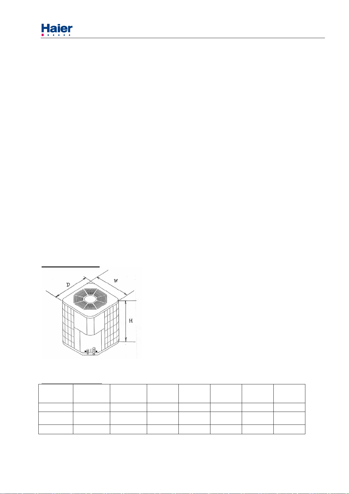
Unit Dimensions
Model:HR18-60C1VAR
----C1VAR HR18 HR24 HR30 HR36 HR42 HR48 HR60
D 23[585] 23[585] 30 1/4[770] 30 1/4[770] 30 1/4[770] 30 1/4[770] 30 1/4[770]
W 23[585] 23[585] 30 1/4[770] 30 1/4[770] 30 1/4[770] 30 1/4[770] 30 1/4[770]
H 31 1/2[802] 31 1/2[802] 27 1/2[698] 31 1/2[798] 27 1/2[698] 31 1/2[798] 35 1/2[898]
[ ] Designates Metric Conversions
Table 6-1
11

Haier Commercial Air Conditioning Model: heat pump, 12SEER UNITS
piston sizes:
Note: the piston placed in the outdoor unit packaging box is used for indoor unit when cooling.
Piston
Size(placed
in package
bag)
Outdoor unit
Indoor coil model
Piston Size
(Installed in
outdoor)
HR18C1VAR
HR24C1VAR
HR30C1VAR
HR36C1VAR
HR42C1VAR
HR48C1VAR
HR60C1VAR
Table 6-2 Piston size
The air distribution system has the greatest effect. The duct system is totally in the control of the
contractor. The industry can only recommend the correct procedure.
The correct air quantity is critical on air conditioning system. Proper operation ,efficiency, compressor life
and humidity control depend on the correct balance between indoor load and outdoor unit capacity .High
indoor air flow increases the possibility of high humidity problems in cooling. Low indoor air flow reduces
total capacity, and causes coil icing. Serious harm can be done to the compressor in either condition.
Air conditioning requires a specified air flow. Each ton of air conditioning requires 400 cubic feet of air
per minute(400CFM/TON).
Duct design and construction should be carefully done. System performance can be lowered
dramatically through bad planning or workmanship. In cooling ,a hot attic can cause a temperature gain
of 3°in the return duct and 4°in the supply duct. This can reduce the cooling capacity of an air
conditioning system by as much as 30%.This means a loss of almost one ton of cooling capacity from a
three ton system.
Air leakage of only 3% in a return duct can cause a 5% loss in system capacity. 3% leakage on a three
ton system is only 30 CFM. Two or three unsealed joints can cause this leak. Sealing the return and
supply ducts pays dividends in increased system capacity and lower operating costs.
Effective duct insulation is essential to prevent loss of capacity and sweating ducts in the cooling mode.
Duct systems installed in the conditioned space can be left uninsulated , but a dense 1/2” fiberglass duct
liner reduces blower and air noises, and prevents sweating ducts when humidity levels are high.
Supply and return duct systems in attics and crawl spaces require a minimum 1” of dense duct liner or 2”
fiberglass wrap with a sealed vapor barrier. A leaky vapor barrier results in duct sweating, causing wet
insulation.
Wet insulation does not insulated .Heat transfer through poorly insulated systems can result in over 50%
loss in operating capacity. Sweating ducts also promote rusting ducts resulting in premature duct failure.
Other duct materials have been successfully used. Carefully follow the duct manufacturers’ installation
instructions. The duct system is only as good as the planners and installers construct.
Air supply diffusers must be selected and located carefully. They must be sized and positioned to deliver
treated air along the perimeter of the space. If they are too small for their intended air flow the become
noisy. If they are not located properly they cause drafts on the occupants in the rooms. Return air grilles
must be properly sized to carry air back to the blower. If they are too small they also cause noise. The
installers should balance the air distribution system to ensure proper air flow to all rooms in the home.
This ensures a comfortable living space.
Refrigerant system diagram refer figure below
HB2400VC1M20
HB2400VC1M20
HB3600VA1M20
HB3600VC1M25
HB4800VA1M25
HB4800VA1M25
HB6000VC1M25
0.068
0.071
0.074
0.078
0.078
0.081
0.081
0.078
0.071
0.081
0.085
0.117
0.108
0.117
7. INSTALLATION INSTRUCTIONS
! WARNING
These instructions are intended as an aid to qualified, licensed service personnel for proper installation,
adjustment and operation of this unit. Read these instructions thoroughly before attempting installation or
operation. Failure to follow these instructions may result in improper installation, adjustment,
service or maintenance possibly resulting in fire, electrical shock, property damage, personal
12
Commercial Air Conditioner Model: heat pump, 12SEER UNITS
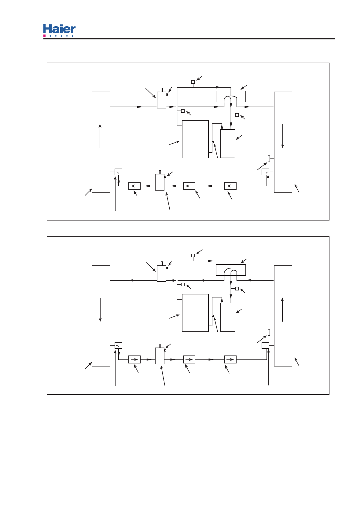
Figure
Cooling
INDOOR COIL
Heat Pump Refrigerant Circuit
SERVICE VALVE
EVAPORATOR
CHECK VALVE
ORIFICE
DISTRIBUTOR
SERVICE PORT
COMPRESSOR
SERVICE VALVE
DISCHARGE TEMP. SENSOR
HIGH PRESSOR
SERVICE PORT
SERVICE PORT
DRYER
DEFROSED SENSOR
CHECK VALVE ORIFICE
REVERSING VALVE
LOW PRESSOR
ACCUMULATOR
CONDENSER
OUTDOOR COIL
DISTRIBUTOR
Heating
INDOOR COIL
SERVICE VALVE
CONDENSER
CHECK VALVE
ORIFICE
DISTRIBUTOR
SERVICE PORT
COMPRESSOR
SERVICE VALVE
DISCHARGE TEMP. SENSOR
HIGH PRESSOR
SERVICE PORT
SERVICE PORT
DEFROSED SENSOR
DRYER
CHECK VALVE ORIFICE
REVERSING VALVE
LOW PRESSOR
ACCUMULATOR
EVAPORATOR
OUTDOOR COIL
DISTRIBUTOR
 Loading...