

Haier HR18D2VAR, HR36D2VAR, HR30D2VAR, HR24D2VAR, HR18D2VAE Service Manual
...
SERVICE MANUAL
●Features
Models
Central Air Conditioning
Haier Hi-Efficiency aluminium fin and copper tube design
Benchmark hermetic compressor design
Powder coated full metal jacket
Efficient performance and economical operation
Durable construction
Quick, easy installation and service
HR18D2VAR
HR30D2VAR
HR36D2VAR
HR24D2VAR
Compact design
Manual code: SYJS-014-07REV.0
Edition: 2007-04-02
Heat pump, Value Series HR13-D2
2
CONTENTS
2. PHYSICAL AND ELECTRICAL SPECIFICATIONS……………….....5
1. DESCRIPTION OF PRODUCTS & FEATURES……………………...3
! Warning !
The equipment detailed in this manual should be installed and
serviced only by qualified technicians who are familiar with the safety
procedures required for this work and who have the proper tools,
testing equipment and replacement parts.
During testing, it may be necessary to work with circuits with live
electrical components. Only individuals with proper training that can
follow all electrical safety precautions should perform this work.
Failure to follow all safety precautions could result in property
damage, serious injury, or death.
3. SAFETY PRECAUTION…………………………………………….…...8
5. ELECTRICAL CONTROL DEVICES…………………………….……..10
7. REFRIGERANT DIAGRAM ………………………………..…….……..13
4. SYSTEM COMPONENTS AND FUNCTIONS ………………………..8
6. APPLICATION…………………..……………………………………..…11
8. INSTALLATION INSTRUCTIONS………………………....…………...13
10. SERVICE AND TROUBLESHOOTING ……………………...……….23
9. MAINTENANCE INSTRUCTIONS………………………………..…….23
11. WIRING DIAGRAMS……………………………….…………………...40
Central Air Conditioning Model: Heat Pump, HR13-D2
3
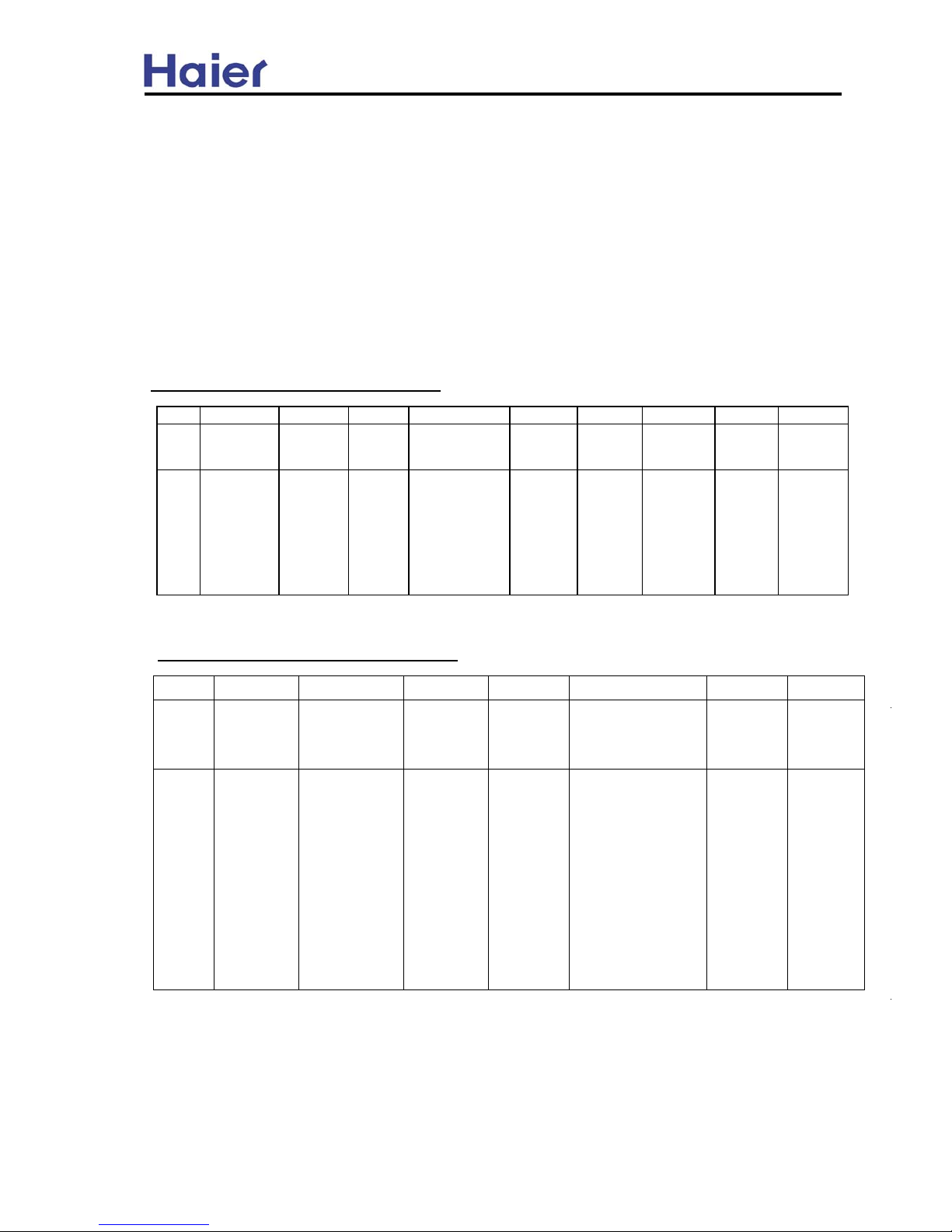
1.2 NOMENCLATURE FOR MODEL NUMBER
Model number explanation---indoor unit
Table 1-1
Model number explanation---outdoor unit
Table 1-2
1.3 ENGINEERING FEATURES:
Haier
System
type
Nominal
capacity in
(1000) Btuh
SEER
designation
Design
series
Electric Designation Body style
H
R
24
D
V A
R
Brand
symbol:
H:
Haier
R: Heat
Pump
24:
24000BTU/h;
60:
60000BTU/h
A:10SEER;
B:11SEER;
C:12SEER;
D:13SEER
E:14SEER;
F:15SEER;
G:16SEER;
H:17SEER
I:18SEER
1:1st
Generatio
n;
2: 2nd
Generatio
n
A:
standard
style
S=Scroll,
R=Recipr
ocating
H B 24 00 V A 1 M 20 P
Haier Blower unit
Nominal
capacity in
Electric
heater
Electric
Designation
Design
series
Airflow
configuration
Unit
Width(in.)
Continuation
Brand
symbol
B:Blower unit
C:Evaporator
W:Wall moun
-ted unit
24:
24000BTU/h
60:
60000BTU/h
00: No;
05: 5KW;
10: 10KW;
15:15KW;
20: 20KW
Y:575V-3Ph-60Hz;
V:208/230V-1Ph60Hz;
60Hz;
D:460V-3Ph60Hz;
A:115V,1 Ph,60Hz
A:10 SEER
A/C coil
A/C coil
A/C coil
1: 1st
Generation;
2: 2nd
Generation;
M:Multi-
direction
V:Vertical
H:Horizontal
paint
1. DESCRIPTION OF PRODUCTS & FEATURES
This manual discusses ‘split’ central air conditioning and indoor coils. “Split” central air condition
system refers to the physical location of major air conditioning components. The split system air
conditioning are manufactured to standards of quality and performance.They are 13 SEER(Seasonal
Engery Efficiency Ratio) which meet or exceed the standards imposed by efficiency legislated and
therefore represent both good value today and for years to come. The current air conditioning system
needs less external protection, while increasing the unit efficiency in cooling mode.
(1000) Btu/h
P: Powder
Efficiency
code
17:17”[432]
22:22”[559]
20:20”[497]
25:25"[625]
A:115V, 1Ph, 60Hz;
60Hz;
D: 460V, 3Ph, 60Hz;
C: 208/230V, 3Ph,
V: 208/230V, 1Ph,
60Hz;
Y: 575V, 3Ph, 60Hz
COPPER TUBE/ALUMINUM FIN COILS: Both indoor and outdoor coils are designed and matched to
optimize heat transfer while minimizing size and cost, with increased durability and reliability.
C:208/230V-3Ph-
D:13 SEER
E:14 SEER
E: EC motor
C:
Condensing
Unit;
Reserved
1.1 Air conditioning
use scroll and reciprocating compressors. This gives the air conditioning a durable compressor which
2
Central Air Conditioning Model: Heat Pump, HR13-D2

4
Fig.1-1
Fig.1-2
safe access to measure unit
nit
pressures .
Fig.1-3
valve in the cooling mode.
Fig.1-4
ACCESSORIES:
CABINETS:
Constructed of powder painted galvanized steel to provide
a durable finish
and protection for the outdoor coil.
FAN GUARD AND MOTOR BRACKET:
BASE PAN: This deep-drawn base keeps the bottom of the coil off the
ground, has weep holes to allow for complete drainage.
LOW AMBIENT CONTROL: This factory installed option allows for low temperature operation in
the cooling cycle ambient temperatures down to 0 ℉
. This control should be installed in units that
operate in cooling when outdoor
ambient temperatures below 65℉
, and is recommended for all
commercial applications.
and system pressure combinations. This option maybe required on reciprocating compressors with
START COMPONENTS : This option provides additional starting for covering a wide range of voltages
SERVICE VALVES AND PRESSURE PORTS: Mounted external to the cabinet for easy access at
installation and during service.
Welded powder coated guard with independent rod and band motor
SERVICE VALVES: Facilitates unit servicing and provides a reliable and
bracket, unit top has a deep draw fan venturi for efficient air flow.
flowcheck piston metering.
FLOWCHECK DISTRIBUTORS: Outdoor units use the Flowcheck Distributor to act as an open check
Central Air Conditioning Model: Heat Pump, HR13-D2

5
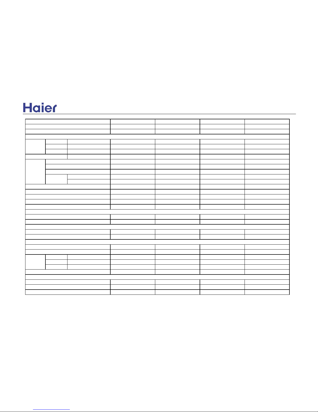
2. PHYSICAL AND ELECTRICAL SPECIFICATIONS
Specifications Subject to Change without Prior Notice
Central Air Conditioning
Model: Heat Pump, HR13-D2
HR18D2VAR HR24D2VAR HR30D2VAR HR36D2VAR
1.5-Ton Outdoor HP 2-Ton Outdoor HP 2.5-Ton Outdoor HP 3-Ton Outdoor HP
New Model New Model New Model New Model
HB2400VD1M20 HB2400VD1M20 HB3600VD1M22 HB3600VD1M22
HB2400VD1M20-P HB2400VD1M20-P HB3600VD1M22-P HB3600VD1M22-P
17,000 22,500 28,000 35,000
12240 16200 20160 25200
4,760 6,300 7,840 9,800
13.0 13.0 13.0 13.0
1,550 2,130 2,570 3,130
15,000 20,000 26,000 32,500
3.3 3.3 3.3 3.3
7.8 7.8 7.8 7.8
1340.0 1730.0 2190.0 2640.0
2000 2000 2350 2840
208/230 - 1 - 60 208/230 - 1 - 60 208/230 - 1 - 60 208/230 - 1 - 60
7.6 10.9 14.0 16.4
15 20 25 30
Reciprocating Reciprocating Reciprocating Reciprocating
H21J14BABCA H21J19BABCA H21J24BABCA H21J30BABCA
5.4 8.0 10.1
11.8
36.0 53.5 61.0 78.0
Yes Yes Yes Yes
Yes Yes Yes Yes
0.86 0.86 1.4 1.6
1/8 1/8 1/4 1/3
1000 1000 1075 1120
175.0 175.0 210.0 325.0
18" 18" 18" 18"
3334
Zinc-Coated Steel Zinc-Coated Steel Zinc-Coated Steel Aluminium
Performance
Electrical
Compressor
with Matching Indoor Unit
Fan Motor
No. of Blade
Fan Material
Condenser coil
Nominal RPM
Input Watts
Diameter (In)
Fan
Crankcase Heater
RLA (Rated Load Amps)
Rated Horse Power (hp)
Model Number
RLA (Rated Load Amps)
LRA (Locked Rotor Amps)
Internal Overload Protection
Minimum Circuit Amps
Maximum Overload Amps
Type / Maker
Total Input Watts (Cooling)
Heating Capacity (Btu/h) (8.3℃)
Heating COP (8.3℃)
Heating HSPF
Total Input Watts (Heating)
Airflow Rate (CFM)
Voltage - Phase - Frequency (Hz)
SEER
Model Number
Comments
Model Status
Cooling Capacity (Btu/h)
Net Sensible Capacity (Btu/h)
Net Latent Capacity (Btu/h)

6
Central Air Conditioning
Model: Heat Pump, HR13-D2
HR18D2VAR HR24D2VAR HR30D2VAR HR36D2VAR
1.5-Ton Outdoor HP 2-Ton Outdoor HP 2.5-Ton Outdoor HP 3-Ton Outdoor HP
New Model New Model New Model New Model
Model Number
Comments
Model Status
1122
0.87 x 0.75 0.87 x 0.75 0.87 x 0.75 0.87 x 0.75
21 21 20 20
Enhanced fins Enhanced fins Enhanced fins Enhanced fins
5/16" Grooved 5/16" Grooved 5/16" Grooved 5/16" Grooved
12.2 12.2 11.9 13.5
4/4 4/4 5/5 5/5
bottle green bottle green bottle green bottle green
Stamped sheet metal Stamped sheet metal Stamped sheet metal Stamped sheet metal
Deep Drawn, Elevated Deep Drawn, Elevated Deep Drawn, Elevated Deep Drawn, Elevated
Easy Access Easy Access Easy Access Easy Access
Full metal jacket Yes Yes Yes Yes
Wire grill Optional Optional Optional Optional
Plastic mesh Optional Optional Optional Optional
Yes Yes Yes Yes
Haier Enhanced Coil Haier Enhanced Coil Haier Enhanced Coil Haier Enhanced Coil
Yes Yes Yes Yes
Yes Yes Yes Yes
Yes Yes Yes Yes
Yes Yes Yes Yes
No No No No
Yes Yes Yes Yes
Yes Yes Yes Yes
Yes Yes Yes Yes
Optional Optional Optional Optional
No No No No
Optional Optional Optional Optional
Yes Yes Yes Yes
No No No No
Yes Yes Yes Yes
Yes Yes Yes Yes
Features Lug.
Accessories
Start Assist Kit
Low Ambient Kit
Compressor Time Delay
Compressor Blanket Kit
Corrosion Resistant Outside Screws
Fan Delay Kit (
Note 1)
Piston
Room Thermostat
Easy Service Access
Galvanized Steel Cabinet
Coil Design
Fully Enclosed Motor
Removable Top Grill Assembly
Elevated Base Pan
High and Low Pressure Switches
Filter Dryer
Full, Reusable Service Valves
Top cover
Basepan
Service panel
Body style /
Coil guard
Gross Finned Face Area (Sq Ft)
Number of Circuits (In/Out)
Exterior Appearance
Cabinet color
Tube spacings (V x H) (In)
Fins per Inch - FPI
Fin Type
Tube OD and Type
Number or Rows
7
Notes:
1-
120-second fan delay for air handler
2-
R-22 Charge for the outdoor unit with matching indoor unit and 25' line set.
Central Air Conditioning
Model: Heat Pump, HR13-D2
HR18D2VAR HR24D2VAR HR30D2VAR HR36D2VAR
1.5-Ton Outdoor HP 2-Ton Outdoor HP 2.5-Ton Outdoor HP 3-Ton Outdoor HP
New Model New Model New Model New Model
Model Number
Comments
Model Status
Height 26 7/8 26 7/8 26 7/8 30 3/8
Width 24 1/4 24 1/4 24 1/4 24 1/4
Depth 24 1/4 24 1/4 24 1/4 24 1/4
Cubic Volume (Cu. Ft) 9.15 9.15 9.15 10.34
3/8" 3/8" 3/8" 3/8"
3/4" 3/4" 3/4" 7/8"
115 115 115 115
Outdoor above Indoor Unit 70 70 70 70
Indoor above Outdoor Unit 50 50 50 50
Re-usable Re-usable Re-usable Re-usable
Sweat Sweat Sweat Sweat
Orifice (057/051) Orifice (062/057) Orifice (071/059) Orifice (078/062)
R-22 / 104.24 R-22/107.77 R-22/141.34 R-22/148.41
10" sides/18" service 10" sides/18" service 10" sides/18" service 10" sides/18" service
167.0 172.0 189.0 207.0
183.0 187.0 205.0 222.0
ARI ARI ARI ARI
UL/cUL UL/cUL UL/cUL UL/cUL
Basiloid Basiloid Basiloid Basiloid
Height 28 1/2 28 1/2 28 1/2 32
Width 26 7/8 26 7/8 26 7/8 26 7/8
Depth 26 7/8 26 7/8 26 7/8 26 7/8
11.92 11.92 11.92 13.38
5555
5555
65 66 68 70
Agency Approvals
Packaging
Warranty(Haier Brand Only)
Dimensions and Installation
Weight (lbs)
Max Vertical
Distance (Ft)
Refrigerant
Line
Service Valves
Refrigerant Connection Type
Unit
Dimensions
(inches)
Liquid Line Dimension (In)
Vapor Line Dimension (In)
Max Refrigerant Line Length (Ft)
Net
Refrigerant Type / Charge (Oz) (
Note 2)
Compressor
Carton Type
Shipping
Carton
Dimensions
Cubic Volume (Cu. Ft)
Parts
Ship
Performance Certification
Safety Approvals
Metering device (Piston size)Cooling /heating
Min Clearances
Noise level dB(A)

3. SAFETY PRECAUTIONS
4. SYSTEM COMPONENTS AND FUNCTIONS
This section describes the various air conditioning components, their purpose and operation. This
section is only a guide and does not consider all components that could be found on an air conditioner in
the field.
Fig.4-1
Generally, liquid refrigerant is suspected if valve damage occurs. Some compressors can tolerate the
gas gives it the name of “low-side” shell compressor
.
The scroll compressor used a helix (similar in shape to a snail shell)
within a similar stationary helix, the moving helix rotates so that the space between the two constantly
decreases as the gas moves toward the center of the Scrolls. The returning refrigerant gas first cools the
motor, then flows into the suction intake of the compressor scroll. The discharge gas leaves from the
center of the helix and exits the compressor. The lower part of the shell should be cool to the touch.
● Follow the manufacturer’s instructions when making repairs, installing replacement parts and
● Use only authorized factory parts.
● Always use industry-recognized service practices in the maintenance, adjustment and repair of the
products covered in this manual.
● Always wear safety glasses when handling refrigerant and peforming brazing operations.
CAUTION: please read all instructions prior to
installing, operating, maintaining or repairing the
product.
WARNING: THE MANUFACTURER’S WARRANTY DOES NOT COVER DAMAGE TO CAUSED BY
THE USE OF ANSUTHORIZED COMPONENTS OR ACCESSORIES, THE USE OF SUCH
UNAUTHORIZED COMPONENTS OR ACCESSORIES MAY ENDANGER LIFE AND
OR INJURY RESULTING FROM THE USE OF SUCH UNAUTHORIZED COMPONENTS OR
PROPERTY. THE MANUFACTURER DISCLAIMS ANY RESPONSIBILITY FOR SUCH LOSS
ACCESSORIES
performing system maintenance.
Current single phase units use two types of compressors. The design of the two compressors types is
to move refrigerant. When paired
.
motor with low pressure
through proper refrigrant control. Returning refrigerant cools the compressor motor and surrounding the
presence of small amounts of liquid refrigerant in the return gas, but this condition must be avoided
are several different types of compressors, but all use electricity to turn an electric motor to drive a pump.
The heart of any refrigerant system is the compressor. It is a pump that causes refrigerant to flow. There
efficiency is reduced.
and low pressure sides of the system. If the valves are damaged, the compressor’s function and
down in cylinders where valves control the flow of refrigerant. The valves provide a seal between high
the driving force is supplied by an electric motor turning the crankshaft and forcing pistons up and
-sor. it operates with an offset crankshaft and pistons, and resembles an internal combustion engine.
Central air conditioners use two types of compressors. The first is the enhanced reciprocating compres-
time delays prevent thermostat short cycling and momentary power interruptions from damaging the
compressor.
-case heaters. The reciprocating compressor may need both. Both types benefit from using a time-delay.
quite different. But they function the same way. Scroll units do not need start components or crank
COMPRESSORS (Fig. 4-1)
8
Central Air Conditioning Model: Heat Pump, HR13-D2
Reciprocating type compressor for HR18/24
Reciprocating type compressor for HR30/36
f
f

Fan
Fig.4-2
Fan and motor assembly
Fig4-3
Flow-Check Pistons
refrigerant metering device controlling refrigerant flow into the evaporator. Second, it acts as an open
check valve when refrigerant flows in the opposite direction.
PROPER MATCH OF UNIT AND PISTON SIZES
Combinations for indoor and outdoor units using a distributor and flowcheck are shown in the application
Mismatching indoor and outdoor units of split systems affects performance, efficiency, charging and
reliability.
Distributor assy
Fig.4-4
Both compressor types are protected internally against over-current and over-temperature conditions.
the contactor coil.
FAN AND BLOWER MOTORS (Fig. 4-2 and Fig. 4-3)
The outdoor component of split system contains an fan motor. These PSC (permanent split capacitor)
Some scroll compressors have an additional thermostat mounted externally in series electrically with
motors are single speed and drive a propeller fan. The motor mounts to the unit top with the shaft up,
This fan pulls outdoor air through the outdoor coil.
To access the condenser fan or motor, carefully remove the unit top, a service loop is provided on the
motor wiring for easier access.
METERING DEVICES (Fig. 4-4)
One type of refrigerant metering device is the flow-check piston. It has two functions. First it acts as a
When refrigerant enters the device from the square end, the piston seats and forces all refrigerant throug
h
the carefully sized hole in the center of the piston. This orifice functions as a metering device controlling
the amount of refrigerant flow, with flow in the opposite direction, pressure moves the piston off the seat
and liquid refrigerant flows around the piston.
Using too small a piston starves the coils of refrigerant. A piston that is too large floods coils.
Split air conditioning indoor and outdoor units must be carefully matched to balance the heat transfer
indoors with the heat resected or claimed by the outdoor unit. Manufacturer's
specification sheets and
installation manuals should be followed to insure proper match. Matched systems are listed on the
internet at ARI. ORG.
table 6-2.
9
Central Air Conditioning Model: Heat Pump, HR13-D2

Fig.4-5
SERVICE VALVES
The stem or core is removable with a flexible seal at its base held closed with a spring. Schrader valves
allow a technician to connect gages to the system with a minimum loss of charge. Use a cap with an
5.ELECTRICAL CONTROL DEVICES
PROTECTION DEVICES
Protection for the unit begins with the installation of appropriate fuses or circuit breakers by the installing
OVERLOADS AND LIMITS
include the automatic reset internal overload in the fan motor and the compressor automatic reset
internal overload. Such controls are not serviceable but their operation may influence service
troubleshooting .For example, the compressor internal overload may stay open for several hours .A
refrigerant pressure exceeds a pre-determined limit of 440 to 460 p.s.i.g. When pressure becomes
THERMOSTATS
In the cooling mode, the thermostat calls for cooling by energizing the compressor contactor and the
indoor blower control. The indoor blower can operate continuously by setting the thermostat subbase fan
switch to the “ON” position.
subbase selection information found in the wiring diagram booklet.
various manual changeover, auto changeover and set-back thermostats or see the thermostat and
accessible by the consumer. Contact your local distributor for information on part numbers of
or “Schrader valve” and the refrigerant line valve. The Schrader valve is like a valve in an automobile tire.
inner seal to prevent leakage and keep dirt and moisture from entering the system.
systems, these valves also hold the charge in the outdoor section from factory.
Refrigerant control valves allow the outdoor unit to be isolated into from the balance of the system. In split
Thermostats are the most obvious control in the air conditioning system because these controls are
contractor. Breaker or fuse size is governed by the National Electrical Code and local code. AMP draw
Overloads protect against over-current or over-temperature conditions. Those located in the outdoor unit
requirements for each unit are found in the Specifications.
technician may incorrectly diagnose this as an open compressor winding.
The high pressure cut-out is a pressure activated switch. It opens an electrical circuit when the
HIGH PRESSURE CUT OUT SWITCH (optional) (Fig. 5-1)
normal, the switch restores automatically.
Fig. 5-1
REFRIGERANT CIRCUIT (Fig. 4-5)
All 13SEER units outdoor coils are multi-circuit. Refrigerent gas or liquid is uniformly distributed to from
There are two types of service valve used on these air conditioning units. They are the service port valve
4 to 10 circuits to improve heat transfer and reduce capacity losses due to pressure drops.
10
Central Air Conditioning Model: Heat Pump, HR13-D2

RELAYS
COMPREESSOR CONTACTOR
contacts ,while others use 2-pole or 3-pole contacts.
compressor and outdoor fan.
OPTIONAL DELAYS AND KITS
before re-starting the compressor.
Defrost PCB
START KITS(OPTIONAL)
This special relay uses the EMF generated by the compressor start windings to take a start capacitor out
of the circuit. The relay and its companion capacitor can start the compressor at low voltages and
against higher pressure, such as those caused by non-bleed port expansion valves.
compressor make a start kit unnecessary.
.
The coil uses 24 volts but the contacts carry line voltage .The heater contactor is a large relay,
which controls the compressor and the outdoor fan operation. Some contactor use single pole
Before specifying any air conditioning equipment, a survey of the structure and a heat gain calculation
The cooling load calculation determines the unit size. There are two capacities that enable the
must be made. A heat gain calculation involves identifying all surfaces and openings that gain heat from
the surrounding air and quantifying that heat gain. The heat calculation also calculates the extra
heaty load caused by sunlight and by humidity removal. These factors must be considered before
selection an air conditioning system to provide year round comfort. The Air Conditioning Contractors
cooling load.
6. APPLICATION
of America (ACCA) J Manual method of load calculation is one recognized procedure for determining the
Fig.5-2
Generally relays used in air conditioning use 24VAC coils. Contact voltage may be either low or line voltage.
Relays provide a method for control switching. Relays may switch either low(24VAC) or line voltage.
Single-pole contactors break only one side of the power feed to the compressor and outdoor fan. The other side
remains connected to the power source. The 2-pole or 3-pole contactor breaks power to all sides of the
CAUTION: WHEN THERE IS A SINGLE POLE CONTACTOR, ONE SIDE OF A 240 V.A.C.CIRCUIT
REMAINS HOT. THIS MEANS THAT THE WIRING IN THE HIGH VOLTAGE CIRCUIT MAY HAVE A
POTENTIAL OF 120V.A.C.TO GROUD. BEFORE SERVICING THE UNIT, ALWAYS TURN OFF
POWDER AT THE UNIT DISCONNECT SWITCH.
A Time-Delay in the compressor contactor lowcontrol circuit allows time for system pressure to equalize
This delay uses solid state circuitry to measure the time since the power was interrupted and is set for
approximately 3 minutes. It is not field adjustable. This is a delay on break timer.
Start kit components should match the recommended ratings and functions of those provided by the
Start kits are not normally required with scroll compressors. The operating characteristics of the scroll
reciprocating compressor manufactorer. See Specifications start components.
Sensible heat is the heat energy
measured on the dry bulb thermometer.
equipment to provide comfort. The first is sensible capacity.
11
Central Air Conditioning Model: Heat Pump, HR13-D2

.
After the proper equipment combination has been selected, satisfying both sensible and latent
● Outdoor unit location
● Proper equipment evacuation
● Outdoor unit refrigerant charge
● Indoor unit air flow
● Indoor unit blower speed
● Supply and return air duct design and sizing
● System air balancing
● Diffuser and return air grille location and sizing
Unit Dimensions
Table 6-1
The second form of heat is called latent heat. This is heat held by the moisture in the air. Removing
this moisture does not affect a thermometer. However, removing the latent heat in the air greatly increase
comfort. A properly sized unit removes both forms of heat, producing a comfortable conditions,
An oversized system cycles on and off quickly and does not properly remove humidify, producing
uncomfortable. The indoor and outdoor equipment combination should be matched by the manufacturer
There are several factors that installers must consider.
and based on engineering data.
conditioning requirements, the system must be properly installed. Proper installation with cerefully
distributed air through adequate duct work will provided a comfortable living space.
12
Model: HR18-36D2VAR
Central Air Conditioning Model: Heat Pump, HR13-D2
W(inch[mm]) D(inch[mm]) H(inch[mm])
Unit 24 1/4[616] 24 1/4[616] 26 7/8[683]
Shipping 26 7/8[682] 26 7/8[682] 28 1/2[725]
Unit 24 1/4[616] 24 1/4[616] 26 7/8[683]
Shipping 26 7/8[682] 26 7/8[682] 28 1/2[725]
Unit 24 1/4[616] 24 1/4[616] 26 7/8[683]
Shipping 26 7/8[682] 26 7/8[682] 28 1/2[725]
Unit 24 1/4[616] 24 1/4[616] 30 3/8[771]
Shipping 26 7/8[682] 26 7/8[682] 32[813]
HR36D2VAR
Dimensions
HR18D2VAR
HR24D2VAR
HR30D2VAR

Table 6-2 Piston size
and humidity control depend on the correct balance between indoor load and outdoor unit capacity. High
Air conditioning requires a specified air flow. Each ton of air conditioning requires 400 cubic feet of air
per minute (400CFM/TON).
of 3°in the return duct and 4°in the supply duct. This can reduce the cooling capacity of an air
conditioning system by as much as 30%.This means a loss of almost one ton of cooling capacity from a
three ton system.
Air leakage of only 3% in a return duct can cause a 5% loss in system capacity. 3% leakage on a three
Duct systems installed in the conditioned space can be left uninsulated , but a dense 1/2” fiberglass duct
liner reduces blower and air noises, and prevents sweating ducts when humidity levels are high.
Supply and return duct systems in attics and crawl spaces require a minimum 1” of dense duct liner or 2”
fiberglass wrap with a sealed vapor barrier. A leaky vapor barrier results in duct sweating, causing wet
Air supply diffusers must be selected and located carefully. They must be sized and positioned to deliver
! WARNING
adjustment and operation of this unit. Read these instructions thoroughly before attempting installation or
P
iston sizes and indoor fan speed:
Note: the piston placed in the outdoor unit package box is used for indoor unit when cooling
.
The air distribution system has the greatest effect. On the quality of the installation and the owner satisfaction,
The correct air quantity is critical for correct air conditioning system. Proper operation, efficiency, compressor life
performance and customer's satisfaction and can cause premature component failure.
Duct design and construction should be done with care. System performance can be lowered
Effective duct insulation is essential to prevent loss of capacity and sweating ducts in the cooling mode.
dramatically through bad planning or workmanship. In cooling, a hot attic can cause a temperature gain
ton system is only 30 CFM. Two or three unsealed joints can cause a leak of this size. Sealing the return
and supply ducts result in full system capacity and lower operating costs.
the duct system is totally in the responsibility of the contractor. These are numerous thchnical associations
Low indoor air flow reduces total capacity, and can causes coil icing. Improper air balance will affect system
and reference that recommend correct procedures.
indoor air flow reduces system dehumidification capacity, and can leave the space humid and uncomfoltable.
Heat transfer through poorly insulated systems can result in over 50%
insulation
does not insulated.
loss in operating capacity. Sweating
ducts also results in rusting that leads to premature duct failure. Carefully follow the industry practices to
7. REFRIGERANT SYSTEM DIAGRAM refer Figure 7
insure a well designed duct system.
treated air along the perimeter of the space. If they are too small for their intended air flow, they can be
noisy. If they are not located properly, they can cause drafts in the rooms. Return air grilles
must be
properly sized to carry air back to the blower. If they are too small they also cause noise. The installers
ensures a comfortable living space.
8. INSTALLATION INSTRUCTIONS
should balance the air distribution system to ensure proper air flow to all rooms in the home. This
These instructions are intended as an aid to qualified, service and instalolation personnel for proper installation
,
service this equipment. Failure to follow these instructions may result in improper installation,
service or maintenance and could possibly result in fire, electrical shock, property damage.
13
Outdoor Indoor
Piston Size
(Installed in
outdoor)
Piston Size
(placed in
package bag)
Indoor fan
speed
HR18D2VAR HB2400VD1M20 051 057 M
HR24D2VAR HB2400VD1M20 057 062 H
HR30D2VAR HB3600VD1M22 059 071 L
HR36D2VAR HB3600VD1M22 062 078 H
Central Air Conditioning Model: Heat Pump, HR13-D2
 Loading...