

Page 1
Installation Manual of Room Air Conditioner
Read this manual before installation
ating means to the user
n
a
h
t
e
r
o
m
AUTO
H
AIR FLOW
HEALTH TEMP+ TEMP-
M
L
m
o
r
e
t
h
a
n
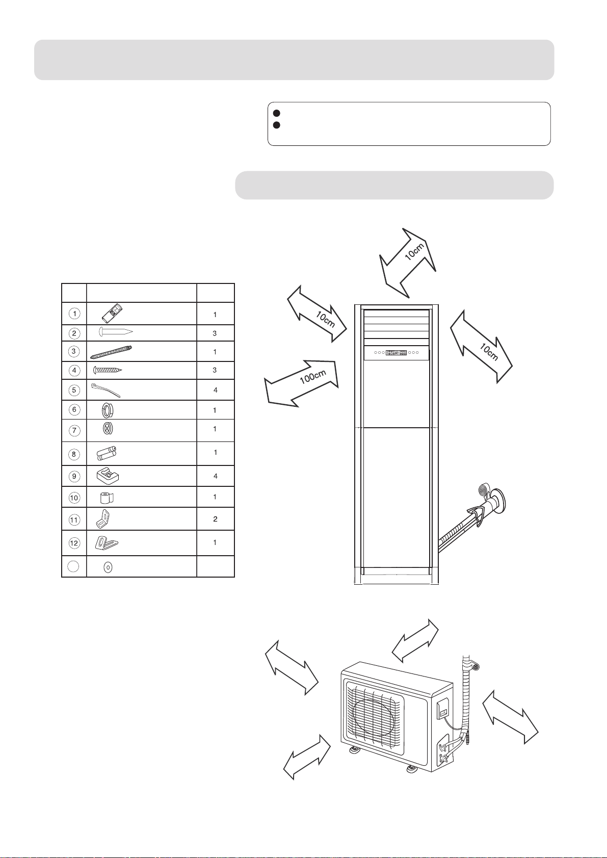
Accessory parts
Shape and description
No.
Remote controller
Cement nail
Drain hose
QTY
Explain sufficiently the oper
according to this manual.
Drawing for the installation of indoor and outdoor units
m
o
r
e
t
h
a
n
ON/OFF MODE
Screw
a
h
wire clip
Wall
hole cover
Piping hole cover
battery #7
Dry
Cushion
Non-adhensive tape
L shape component
anti-fall componen
13
gasket
t
3
t n
e
r
o
m
m
c
0
1
n
a
h
t
e
r
o
m
o
r
e
t
h
a
n
1
0
c
m
m
No.0010513342
m
o
r
e
t
h
a
n
1
0
c
m
m
c
0
6
n
a
h
t
e
r
o
m
Page 2
6
52
043
500140 140
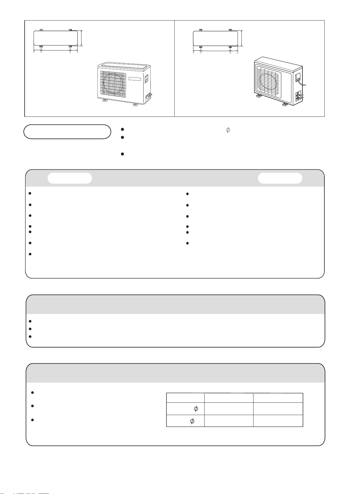
Floor fixing dimensions
of the outdoor unit
(Unit:mm)
HPU-18CRA13 HPU-20CRA13
Fixing of outdoor unit
Fix the unit to concrete or block with bolts( 10mm) and nuts firmly and horizontally.
Floor fixing dimensions
of the outdoor unit
(Unit:mm)
When fitting the unit to wall surface, roof or rooftop, fix a supporter surely with nails
or wires in consideration of earthquake and strong wind.
If vibration may a
Indoor Unit
Place, robust not causing vibration, where the body can be supported
sufficiently.
Place, not affected by heat or steam generated in the vicinity, where
inlet and outlet of the unit are not disturbed.
Place, possible to drain easily, where piping can be connected with the
outdoor unit.
Place, where cold and warm air can be spread in a room entirely.
Place, nearby a power receptacle, with enough space around. (Refer
to drawings).
Place where the distance of more than lm from televisions, radios,
wireless apparatuses and fluorescent lamps can be left.
Do not make the air flow blows directly to the bed when installing the
indoor unit.
Selection of Installation Place
ffect the house, fix the unit by attaching a vibration-proof mat.
Place, which is less affected by rain or direct sunlight and is
sufficiently ventilated.
Place, possible to bear the unit, where vibration and noise are
not increased.
Place, where discharged wind and noise do not cause a
nuisance to the neighbors.
Place with enough space for smooth air flow.
The air conditioner should not be installed on the
unprofessional metal frame (f.g. guard against theft net)
The outdoor unit should be installed above the ground
2.5m beside the street.
635113.5 113.5
Outdoor Unit
Power Source
Before inserting power plug into receptacle, check the voltage without fail. The power source is the same as the corresponding name plate.
Install an exclusive branch circuit of the power.
A receptacle shall be set up in a distance where the power cable can be reached. Do not extend the cable by cutting it.
Selection of pipe
To this unit, both liquid and gas pipes shall be insulated
as they become Iow temperature in operation.
Use optional parts for piping set or pipes covered with
equivalent insulation material.
The thickness of the pipe must be 0.8 mm at least.
Liquid pipe( )
Gas pipe( )
2
For 18 For 20
6.35mm(1/4")
12.7mm(1/2")
9.52mm(3/8")
15.88mm(5/8")
Page 3

Installation Manual of Room Air Conditioner
1.Installation of the Indoor Unit
(1 ) Position of the wall hole
Wall hole should be decided according to installlation
place and piping direction.(refer to installation drawings).
( 2 ) Making a wall hole
Make a hole , with a little slope towards outside.Install
piping hole cover and seal it off with putty after installation.
Indoor side Outdoor side
Wall hole
(side elevation of wall hole)
Thickness
of wall
( 3 ) Fasten the indoor unit
For preventing overturn, fasten the upside of the indoor unit onto the wall
with the anti-fall components and downside part on the floor with L shape
screw
component. Please install the whole unit horizontally and keep the unit
pitch within 1 degree.
The anti-fall component installation
Fasten the component onto the wall (fig. 1)
Keep the unit vertically and adjust the hole of the component,
and keep it unite with the unit tightly; then fasten the bolt (fig. 2)
L component installation
Do not make gap between the component and the unit, fasten the L-shape component with the unit with the bolts (fig. 3).
After making sure the unit keeps vertical, fasten the L-shape onto the floor with the bolts (fig. 4).
(fig. 1)
(fig. 2) (fig. 3) (fig. 4)
anti-fall
component
(accessory)
L shape
component
(accessory)
2. Piping connection
AUTO
H
MODE
ON/OFFAIR FLOW
HEALTHTEMP+ TEMP-
M
L
Connecting method
To bent a pipe, give the roundness as large as possible not to crash the pipe. When connecting pipe, hold the pipe
center to center then screw nut on by hand, refer to Fig. Be careful not to let foreign matters, such as sands enter
the pipe.
Forced fastening without careful
centering may damage the
threads and cause
a leakage of
gas.
Pipe Diameter ( )
Liquid Side 6.35mm(1/4")
Liquid Side 9.52mm(3/8") 42N.m
Gas Side 12.7mm(1/2")
Gas Side 15.88mm(5/8")
Fastening Torque
18N.m
55N.m
60N.m
3
Page 4

Installation Manual of Room Air Conditioner
( 1 ) Arrangement of connecting pipe and drainage pipe
After opening inlet grill, you will see a control box as shown in the below left picture. Remove the cover before working.
According to the piping method, connect the piping on indoor unit with union of connection pipe. Arrange the piping as
per the wall hole and bild drain hose connecting electric cable and piping together with polyethylene tape.
Insert the bound piping connecting electric cable and drain hose through wall hole to connect with outdoor unit.
Please see the below right picture.
According to the hole location, install the connection pipe and tie up the soft drain pipe, connection cable, and connection
pipe with the polyethylene adhesive tape, and then drill through the prepared hole so as to connect with the outdoor unit.
AUTO
H
MODE
ON/OFF AIR FLOW
HEALTH TEMP+ TEMP-
M
L
Piping
control box
Heat insulation
material
Drain hose
( 2 ) Arrangement drain hose
Drain hose shall be placed in under place.
There should be a slope when arrange drain hose. Avoid up and down waves in drain hose.
If humidity is high, drain pipe(especially in room ) must be covered with installation material.
3. Piping connection of the outdoor unit
Purging method
Push the air out of the indoor unit
and piping as followes:
(1) Remove the valve cap on 2-way valve in outdoor unit.
(2) Loosen by 1~2 circle the flare nut of gas pipe,
which is conneted to 3-way valve.
(3) Loosen 2-way valve by 90
o
using hexagon wrench,
and after approx. After approx 15 sec tighten it up.
Gas comes out through flare nut on wide pipe. If no
gas is discharged, tighten flare nut with specified torque.
(4) Open 2-way and 3-way valves using specified torque.
(5) Tighten the caps on the valves with specified torque.
way valve
2-
6.35mm(1/4")
HPU-18CRA13
Indoor/outdoor
electric cable
3-way valve
12.7mm(1/2")
way valve
2-
9.52mm(3/8")
way valve
3-
15.88mm(5/8")
Tighten torque N.m
Valve rod
Valve cap
7-9
20-25
HPU-20CRA13
Note: When additional refrigerant is necessary, first purge air out of connecting pipe by external gas,
then drive out the excessive refrigerant by purging method.
Brand new unit is charged 80g more refrigerant than regulated werght. This is only for first installation
to purge air in the indoor unit and connecting pipe.
When piping is longer than 5m,charge additional refrigerant specified in this list.
HPU-18CRA13:
Pipe length 5m
Refrigerant charge(g)
10m
100
15m
200
20m
300
HPU-20CRA13:
Pipe length 5m
Refrigerant charge(g)
10m
300
4
15m
600
20m
900
Page 5

Installation Manual of Room Air Conditioner
Electric wiring
Note
Electric wiring must be done by qualified person.
Use copper wire only.
Wiring of indoor unit
Insert the cable from outside the wall hole where piping already exist.
Put it out from front.
Losen terminal screw and insert cable end fully into terminal block, then tighten it .
Pull the cable gently to make sure it is tight.
Replace cover after wiring.
The parameter of the connecting wiring:
Terminal block
Wire clip
wire loop
Outdoor unit
1
4 5
Indoor unit
(
L
)
POWER
Wiring of outdoor unit
Insert the cable from inside the wall hole where piping already exist.
Pull it out from front.
Loose terminal screw and insert cable end fully into terminal block, then tighten it.
Replace cover after wiring.
Note:
When connecting indoor and outdoor wire, check the number on indoor and outdoor terminal
blocks. Terminals of same number and same coulor shall be conneced by the same wire.
Incrrect wiring may damage air condioner's control or cause operation failure.
5
Page 6

Installation Manual of Room Air Conditioner
Others
1.Power supply
Air conditioner must use an exclusive line(over 20A).
There is not power plug with the type of 18k, and there is not power cable with the type of 24k.
When installation air conditioner in a wet place , try to use a circuit breaker against current
leakage.
For installation in other places, use circuit breaker as far as possible.
2.Piping cutting and flaring
Be sure to carry out deburring after cutting with a pipe cutter.
Insert flaring tool to make a flare.
Pipe diameter
A
Flare tooling die
Liquid pipe
Gas pipe
Liquid pipe
Gas pipe
6.35mm(1/4")
12.7mm(1/2")
9.52mm(3/8")
15.88mm(5/8")
Size A (mm)
0.8~1.5
1.2~2.0
1.0~1.8
1.4~2.2
Correct Incorrect
Lean
Damage of flare Crack PartialToooutside
Installation inspection and test run:
Please operate unit according to this manual.
Items to be checked during test run. Please made a " " in " "
Are there any gas leakage?
How is insulation at piping connection carried out?
Are electric wires of indoor and outdoor unit firmly inserted into terminal block?
Is electric wiring of indoor and outdoor securely fixed?
Is drainage securely carried out?
Is earth line(grounding) securely connected?
Is power supply voltage abided by the code?
Is there any noise?
Is control display normal?
Is cooling operation normal?
Is room temperature regulator normal?
6
 Loading...