

Page 1
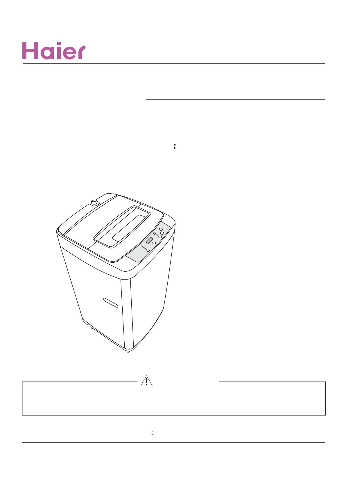
SERVICE MANUAL
Orde r NO . TL14 03S006V1. 1
Automatic Washing Machine
Model NO
HLP24E
WARNING
This service information is d es ig ne d f or experienced repair technicians onl y a n i s n or de si gn ed for use by the general
public. It does n ot co nt ai n w ar ni ng s or cautions to advise non-technical in di vi du al s of potential dangers in attempting t o
service a product. Pro du ct s p ow er ed by electricity should be serviced or r ep ai re d only by experienced p ro fe ss io na l
technicians. Any a tt em pt to se rv ic e or re pa ir the products dealt wi th in t hi s s er vi ce inf or ma ti on by anyone else could
c year(Full name of t he co mp an y w ho is su es th e serv ic e i nf or ma ti on ).
All rights reserved. Una ut ho ri ze d c op yi ng and distribution is a vi ol at io n of law.
Haier Group
Page 2

Service Manual
Order No. TL1001S001V0
Chapter 1: General Infromation
1-1. Table of Contents
Issue
Rev.
Document control
Chapter 1. General Information ............................................................................... 2
1-1. Table of Contents 2
1-2. General Guidelines 3
1-3. Caution and Warning symbols 3
1-4. Function indication symbols 3
Chapter 2. Product Feature
2-1. Features 4
2-2. Specifications 5
Chapter 3. Safety Precautions
3-1.
Safety 6
3-2. Warning and cautions 7
3-3. Net Dimensins 8
Chapter 4. Installation and accessory parts
4-1. Key points in installation
4-2. Installation the button plate
4-3. Adjustment of the installation position
4-6. Usage of operation buttons
4-7. Product briefs
4-8. Key points in disassembly
Chapter 6. Maintenance service and trouble shooting
Trouble alarm
6-1.
6-2. Trouble shooting charts
6-2-1. No action(the indicator is off)
6-2-2. No water filling
6-2-3. No rotation in washing or(rotate to one direction)
6-2-4. No draining
6-2-5. Keep filling water
6-2-6. No spinning
6-2-7. Too much spinning noise
6-2-8. Too much noise in washing
6-2-9. The tub rotates to one direction(in washing)
6-2-10. Brake time out
.........................................................................................................
.......................................................................................
.......................................................................................
.....................................................................
.....................................................................
....................................................................................... 4
.......................................................................................
.......................................................................................
.......................................................................................
.........................................................................................................
.......................................................................................
.......................................................................................
.............................................................
.......................................................................................
.......................................................................................
.....................................................................
.......................................................................................
.........................................................................................................
.......................................................................................
.............................................
and solve
.......................................................................................
metho
.......................................................................................
.......................................................................................
.......................................................................................
.......................................................................................
.......................................................................................
.......................................................................................
d
.......................................................................................
.......................................................................................
.......................................................................................
.......................................................................................
.......................................................................................
11
12
13
17
17
18
18
19
19
20
20
21
21
22
22
23
1
6
8
8
8
9
Chapter 7. Wiring diagram
.........................
.................................................................24
Page 3
Service Manual
Order No. TL1001S001V0
Issue
Rev.
1-2. General Guidelines
When servicing,observe the original lead dress.If a short circuit is found, replace all parts which are
overheated or damaged by the short circuit.After servicing ,see to it that all the protective devices such as
insulation barriers ,insulation papers shields are properly installed .Confirm that the screws,parts and wiring
which were removed in order to service are put in the original positions, or whether there are the portions
which are deteriorated around the service places serviced or not. And be sure safety of that.
1-3. Caution and Warning symbols
(You will see them in Matters needing attention )
Any instructions in this service manual with this Warning sign must be followed strictly.
To prevent damage to the washing machine, any instructions in this manual with this
Stop sign must be followed strictly.
1-4. Function indication symbols
(You will see them in the specification table)
Signify the washing machine has this function.
<
Signify the washing machine doesn t have this function.
X
3
Page 4
Service Manual
Order No. TL1001S001V1.1
Chapter 2: General Infromation
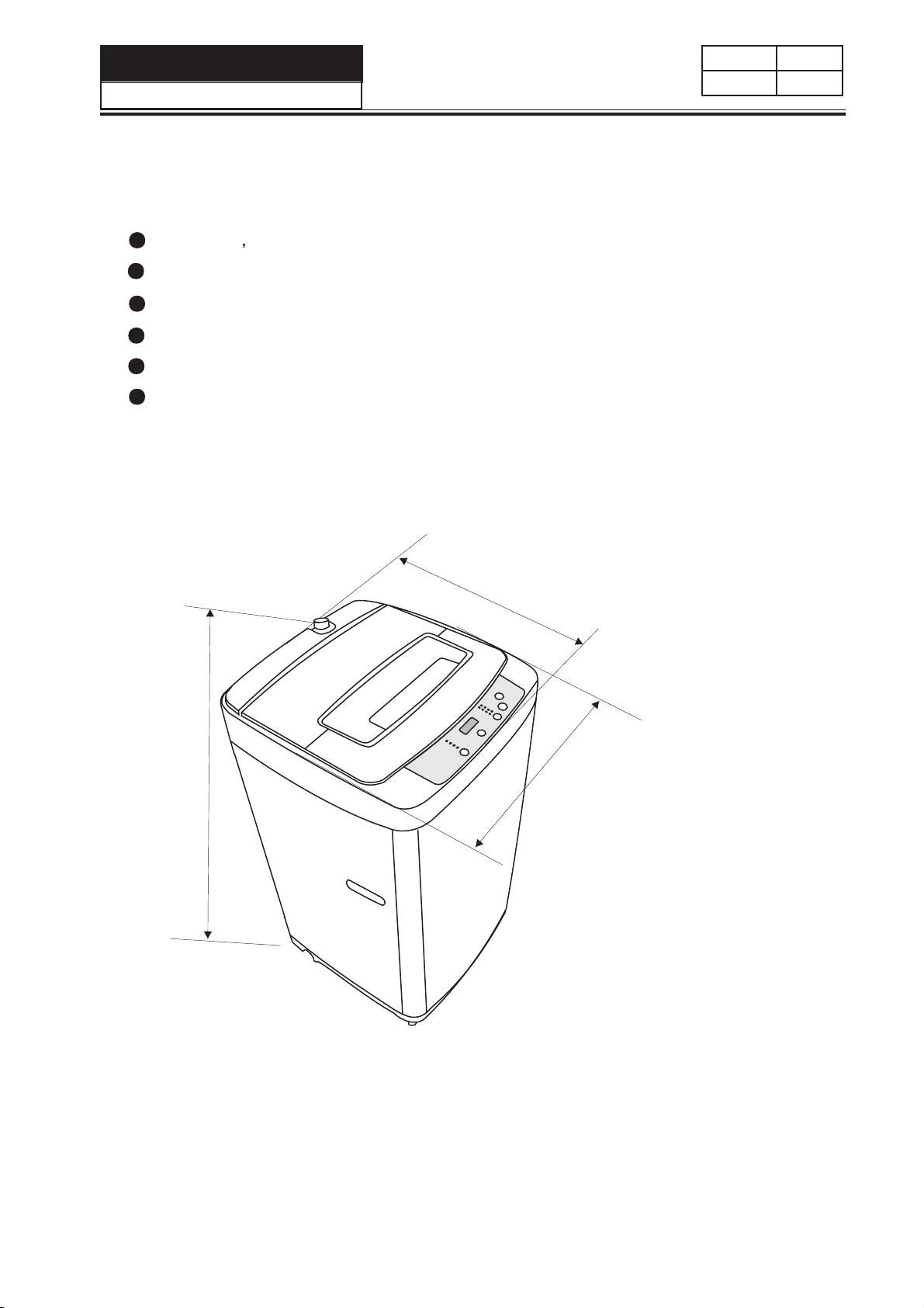
2-1 FEATURES
Soak wash make cleaner wash.
Fashionable appearance, transparent top lid
Efficaciously reduce noise
Automaticly power off function
Self-adjustment to unbalance of laundry in spinning
Fuzzy computer control, self-program function, more
convenient washing
2-2 Net Dimension
Issue
Rev.
902
510
500
Unit:mm
4
Page 5
Service Manual
Order No. TL1001S001V0
2-2 SPECIFICATIONS
Issue
Rev.
Model
Free standing
Built under
EAN code
Energy efficiency class
Features for use
Wash capacity
Spin capacity
Level/Volume
Preset
Residual dampness
Control model
Controller
Normal computerized
Fuzzy computerized
Frequency conversion
Service features
Programs
Short cycle
Inlet water select
Heating selection
Spinning cycle (selector)
Spinning cycle (variable)
Start/Pause
Automatic balancing
Aesthetics
Cabinet material P=Plastic/Z=Zincking
/C=Cold rolled stainless steel )
Inner drum (stainless steel=s / plastic=p)
Drain type
Door (glass=g / plastic=p)
Adjustable feet
Technical data
Voltage/frequency
Energy consumption
Water consumption
Wash power
Spin power
Special function
Air-Bubble
Feet wheel
Spray current
Dimensions (measurements)
Height / built under
Width include drain pipe)
Depth / with open door
Dimensions packed ( measurements packed)
Height
Width
Depth
Net weight
Gross weight
20'Container load
40'Container load
40H Container load
Kg
Kg
L
H
%
V/Hz
kwh/kg
L/kg
w
w
mm
mm
mm
mm
mm
mm
kg
kg
Sets
Sets
Sets
HLP24E
7704353033123
-
5.0
5.0
Small/Medium/Large/Super
<115
8
C
S
Drain up
G
120/60
24
325
255
902
500
510
986
582
582
28
30
60
120
168
5
Page 6
Service Manual
Order No. TL1001S001V0
Chapter 3. Safety Precautions
3-1. Safety
Issue
Rev.
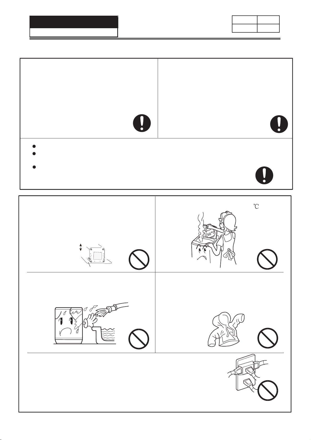
Please plug the power plug on special
receptacle. Be sure to use three-pins
power receptacle. Ensure that the earthing
prong of the power receptacle is earthed
reliably. Use leakage protector if possible.
The washing machine must be positioned
so that the plug is accessible. Be sure to pull
the plug off and close the water faucet in
following cases: power failure, delivering
the machine, setting the machine idle or
cleaning the machine.
Do not plug or pull the
power plug with wet
hand.
Do not bend ,extend, twist, bind by force. Do not press or nip it with weight.
Keep the pin of the power plug clean, if the power plug is polluted with dust,
please wipe with dry cloth carefully.
If the supply cord is damaged, it must be replaced by
the manufacturer or its service agent or a similarly
qualified person in order to avoid a hazard.
In case the washing machine is installed
Do not use water hotter than 50 .
on ground with carpet, do not block the
ventilation hole with carpet.
Ensure carpet does not
obstruct the
opening in
the bases.
Front
Back
Carpet
Do not put the machine at damp place
like the bathroom. Never wash it with
water. Do not put wet laundries on the
control panel.
Do not wash water-proof laundries like
the raincoat, bike covers etc. to avoid
abnormal vibrations in spinning.Wash
the clothes that can float on the water
surface easily,please be careful
especially,for
fear damage.
Do not let the machine share one receptacle with other
electric appliances. If the plugging into the receptacles
loose, do not use the plug any more.
6
Page 7
Service Manual
Order No. TL1001S004V0
3-2.Warning and Cautions
Issue
Rev.
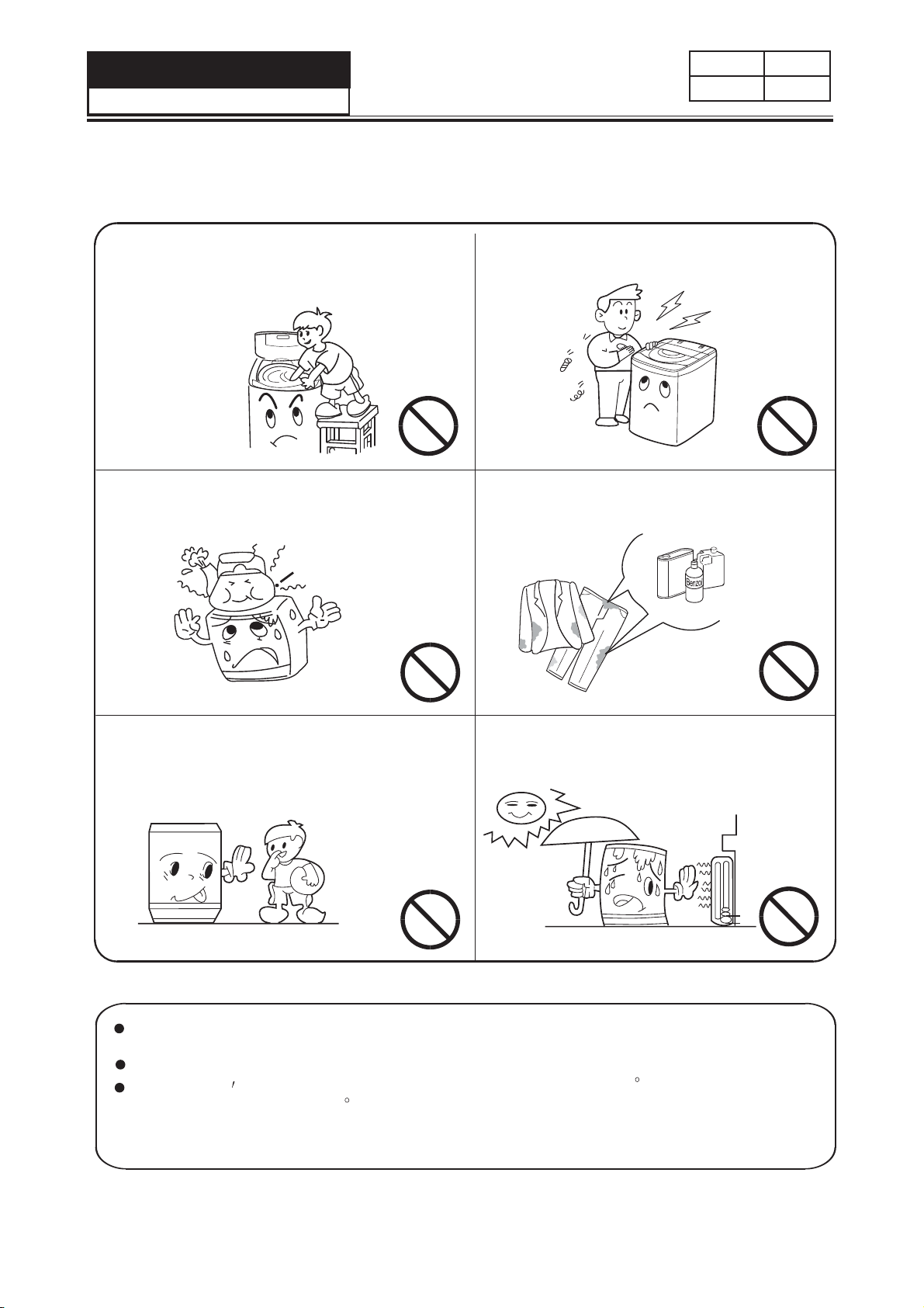
Do not stretch hands into the working
machine. It is dangerous even if the
rotation is slow. Take special care of
the children.
Do not put any hot or heavy items (such
as the kettle with hot water ) on the
washing machine.
Do not decompose, repair or alter the
machine by yourself.
Do not wash laundries with volatile
materials (such as thinner, petrol etc.)
Thinn
er
Petrol
The children shall not approach
the working washing machine.
Keep the machine away from direct
sunlight and heat source like the heater.
Please check if the water faucet is open, and if the connection of the
water inlet pipe is proper.
It is suggested to use foamless washing powder.
Please don t use the washer in the environment below 0 C; if the washer
has been stored below 0 C, please be sure to ensure the washer is placed
under the room temperature more than 2 hours and then use otherwise
the washing effects may be lowered or the washer may be damaged.
7
Page 8

Service Manual
Order No. TL1001S001V1.1
Issue
Rev.
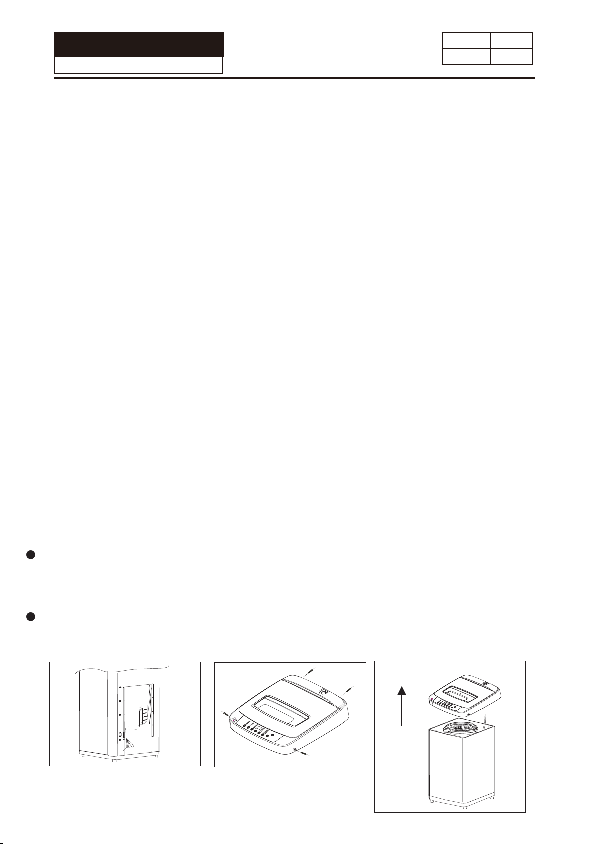
Chapter4 Installation and accessory parts
4-1.Key points in installation
Please install and adjust the machine according to the requirement of the mannual.
It is very important to your security and correct operating the machine.
4-2 Adjustment of the installation position
The washing machine away from wall should be overrun 20mm. The largest
allowable slope of the shank base of the machine is 2 The slanting or rough
ground will result in unstable running or stoppage of the machine. Please adjust
it with following methods:
Confirm it's horizontal:
Hang the lead line to check if it is horizontal.
Adjust the adjustable leg:
Please lift up the side of the leg slightly,
twist the adjustable leg, make sure to keep the
washing machine in balance
High
Adjustable leg
low
8
Page 9

Service Manual
Order No. TL1001S001V0
4-4.Usage of operation buttons
Issue
Rev.
WASH CYCLE BUTTON
Use this button to select the desired cycle for your wash load.
Ţ
The standard default settings of each cycle will be displayed; the default
Ţ
settings can be changed by using the Setting button - Water Level.
There are 6 cycles to choose from:
Ţ
Heavy Duty - Use this cycle for heavily soiled durable garments. This cycle
can also be used for towels, sports gear, children’s clothes, etc.
Normal - Use this cycle for normally soiled cottons and mixed fabric loads.
Delicate - Use this cycle to wash lightly soiled garments and delicate clothes
that need gentle washing.
Quick - Use this cycle to wash small, lightly soiled loads that are needed in a
hurry.
Rinse & Spin - Use this cycle for removing excess detergent and refreshing
clean garments.
Spin Only - Use this cycle to extract water from sink washed or clean wet
garments.
SETTING BUTTON
Water Level Button
Use this button to select an appropriate water level for your load. Small is
Ţ
the lowest water level and Super is the highest.
9
Page 10

Service Manual
Order No. TL1001S003V0
Issue
Rev.
DELAY START BUTTON
Press this button to delay the start of your wash cycle between 1 - 24 hours
Ţ
in one hour increments.
Use this button to select a delayed start of the washer. The number of hours
Ţ
will be shown in the Estimated Time Remaining Display. Each press of the
Delay Start Button will increase the time by 1 hour.
One button press after 24 will cancel the Delay Start feature. You can also
Ţ
POWER Button.
The START/PAUSE Button must be selected to begin the countdown.
Ţ
ESTIMATED TIME REMAINING DISPLAY
The Estimated Time Remaining Display shows the estimated cycle time in
Ţ
minutes.
When the Delay Start option is being used, the Estimated Time Remaining
Ţ
Display will show the delay time in hours.
START/PAUSE BUTTON
Press this button to start a selected cycle or to pause an operating cycle.
Ţ
NOTE: After starting the wash cycle, you must pause the operating cycle to
change the Water Level setting.
POWER BUTTON
Press the POWER button to turn on the washer.
Ţ
NOTE: If the washer is turned on, but START/PAUSE is not pressed, the power
10
Page 11

Service Manual
Order No. TL1001S003V1.1
Issue
Rev.
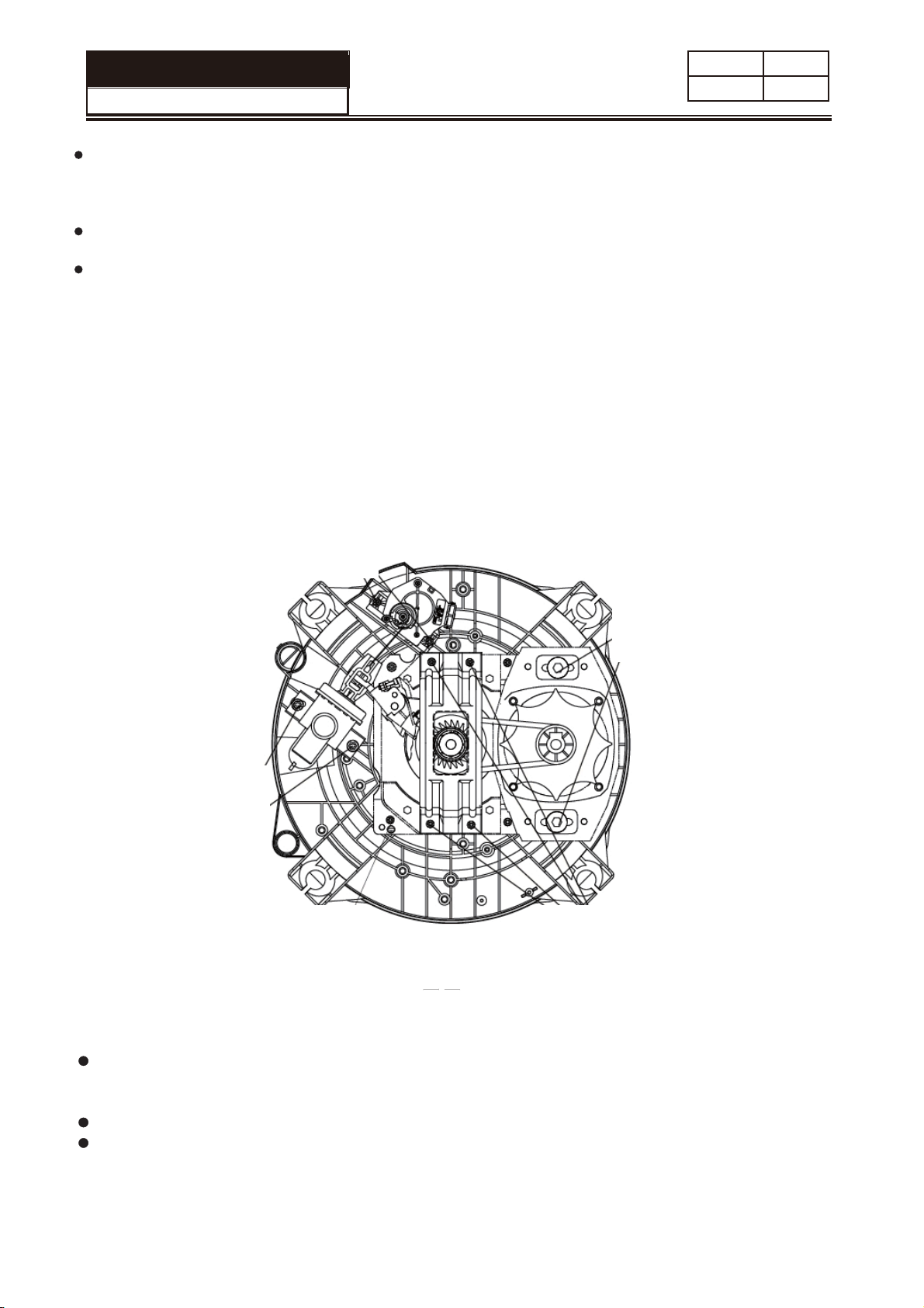
4-5 Product Brief
1)Computer sequencer
It adopts pouring seal with polyurethane on the surface. The light-emitting diode
is sealed with insulation bushing to avoid humidit
of computer plate and box and the operation components of the control panel seat
are coated with control panel film.
2)Structure of the top lid
The top lid adopts transparent view window structure. If the top lid is closed, you
can observe the running of the washing machine through the transparent lid.
3)Power transmission system
During washing, the rotation of Motor 1 is transferred to Follower 6 from Drive
Wheel 2 through Belt 3. Meanwhile, the puller makes the first action. The brake
belt is departed. Pawl 9 and 10 brake the Ratchet 5 and 8 by the action of spring.
y
To avoid splashing, the surface
.
The force will be transferred to Center Gear11, and then be retarded and
transferred to Tie-rod 13 through a planetary gear mechanism consisting of Center
Gear 11, Planet Gear 12 and Spin Shaft 4 (inner gear), then Tie-rod 13 is
connected to Pulsator 14 via a spline shaft. The Pulsator 14 will move along with
the clockwise and counterclockwise rotation of the Motor 1. The Spin tub 15
rotates to the opposite direction against the pulsator by the action of the retarder
planetary gear mechanism.
During spinning, the rotation of Motor 1 is transferred to Follower 6 from Drive
Wheel 2 through Belt 3. Meanwhile, the puller will make the second action. The
Pawl 9 and 10 will leave Ratchet 5 and 8 by the action of the puller. Clutch Reed 7
is twisted tightly on the down part of Spin Shaft 4. The Spin 15 and Spin shaft 4
adopt flange connection. The movement of Motor 1 is retarded by V-belt 3, and
make Spin tub 15 spin through Spin shaft 4.
4)Damping system
Please pay attention in installation of the hangers that the spring of the hanger
at the motor side (two) is different from those installed on the other hangers (two).
11
Page 12
Se r vice Manual
Model No: TL1001S003V0
Issue
Rev.
Key points in disassembly
General attention
Be sure to pull off the power plug in disassembly or maintenance
Use stipulated crimo terminals in connecting the wires between the
conducting wires as far as possible ,and fix with suitable tools ,and insulate
with insulation tape completely .
In inserting the conducting wires ,be sure to plug the pins to the root and
make it hard to be pulled out .
If welding is needed ,be careful not to touch the plastic or other insulation
parts and the parts with the iron .
When connecting the wires ,be sure not to make the wire touch the mobile
parts like the belt ,radiating pulley and jib ect.,and the sharp protruding
parts and the parts with high temperature (motor ). Connect and fix the wires
as per their original mode .
If there is metal object at the wire fixing point,be sure to insulate with in
sulation materials,
Retain the dismantled screws of future usage in installation ,
Points of attention in usage of electic components
In case that the power is on ,the earthing circuit of the computer sequencer
can have 120V voltage to earth.Take care not to get electric shock .
Store the computer sequencer and driver under 4 degree to 30 degree ,
Avoid direct sunlight .
In trouble -shooting ,it may require hot-line work .Please be extremely .
1.Method of opening panel seat
A.Open the back cover .Loosen the locking belt fixed on the cabinet(used
inner wiring ),to loosen the inner wiring
B. Loosen the four screws used to install the control panel seat (rear and side)
C.Lift the rear upwards.Loosen the control panel seat from the inlay of
Attention :
Do not lift the control panel seat by force ,otherwise the safety switch control
rod may get transformed.and the jointer part of the connecting pipe of the
water level sensor may be loosened ,therefore influence the normal
operation of the microswitch and water level sensor .
After opening the control panel seat ,hold it with one hand or lean it on
supporter like the wall .Do not put it down .
First loosen the screws when dismantling the computer controller .
12
Page 13
vice Manual
r
Se
Model No: TL1001S003V1.1
Attention :
Do not lift the control panel seat by force ,otherwise the safety switch control rod may get
transformed.and the jointe
loosened ,therefore influence the normal operation of the microswitch and water level
sensor .
After opening the control panel seat ,hold it with one hand or lean it on supporter like the
wall .Do not put it down .
First loosen the screws when dismantling the computer controller .
3)Method cabinet and outer tub of disassembling
A.Loosen the two motor bolt unit to dismantle the motor.To adjust the
tension of the blet ,loosen the bolts and move the motor left and right .
B.Loosen the four fastening screws to dismantle the delivery shield .
C.Loosen the three fastening screws to dismantle the drain motor .
D.dismantle the drain pipe ,
E.In dismantling the inner tub ,first take offthe outer tub cover ,then
dismantle the pulsator ,finally dismantle the inner tub .Handle with care
when taking the inner tub off from th
r part of the connecting pipe of the water level sensor may be
e outer tub
.
Issue
Rev.
4)Points of attention in assembly
In installation of thedrain pipe ,please smear a piece of 801 glue at the connection
part between the drain pipe and outer tub and between the overflow hose and drain
hose to guarantee that the drain pipe will not leak .
In fastening the screws ,make it tight without sliding .
Take care not to scratch the cabinet and influence the appearance of the machine .
13
Page 14

Service Manual
Model No: TL1001S003V0
Chaper5.PARTS AND FUNCTIONS
Front Vie w
2
Issue
Rev.
1
3
6
1.
Top Lid
Control Panel
2.
Washer Cab inet
3.
Adjustable Leg
4.
Back View
11
9
10
4
5. Cab inet
5
Handle
(loca ted on
bo th
sidesof thewasher)
6.Drain bushing
7. Screw co ver
8
7
14
12
8. Water inlet valve
9. Water absorption cushion
10. Power cord(120Volt/60Hz)
13
11. Back cover
12. Fixed foot
13. Adjustable foot film
14. Hanging hole
14
Page 15

Service Manual
Order No. TL1001S003V0
Issue
Rev.
Chapter. 6 MAINTENANCE SERVICE AND TROUBLE SHOOTING
Phenomena The reason How to settle
The digitron displays dO. The top lid is open during
reserve procedure.
The drainage cannot
work, or is too slow. The
digitron displays Ld.
It stops running in
midway. The digitron
displays
The safety switch acts,
and the spinning cannot
work. The digitron
displays
not work, or is slow, the
digitron displays
The digitron displays FA. The water level sensor is bad. Please contact the after-sales service
The
machine
does not
act
dO.
uL.
LF.
Not wash Is there power failure?
Not spin
Is the drain hose blocked?
The top lid is not closed.
When using the child lock function,
if the top cover is opened, the
machine will stop and display dO
alarm. After 5 minutes the machine
will automatic drainage
Are the laundries put slantingly?
Is the machine slanting?
Is the water tap opened, or is
there water supply failure?
Is the water inlet valve blocked?
Is the water pressure too low?
Is the power plug inserted tightly?
Is the water level reached preset
position?
Is the power plug inserted tightly?
Is the top lid closed reliably?
Close the top lid.
Put down the drain hose . Open and
close the top lid once.
Clean the foreign material. Open and
close the top lid once.
Close the top lid.
clear the dO alarm, please close the top
cover and press the START/PAUSE ”
button. Then dO alarm will be cleared.
Reorder the laundries. Close the top lid.
Place the machine horizontally, open
and close the top lid once.
Open the water tap. Open and close the
top lid once.
Clean the water inlet valve then open
and close the top lid once.
Use after the water pressure is normal.
department.
Please use it when there s power
supply.
Insert the power plug tightly.
Fill water to the preset position.
Insert the power plug tightly.
Close the top lid.
There is abnormal sound
inside the machine
The water tap leaks
Is the machine slanting?
Are the laundries put slantingly in
spinning?
Are there any foreign materials?
Is the screw of the jointer of water
inlet hose loose or awry?
Adjust the machine to be even
Reorder t he laundries and close the top
lid.
Remove the foreign materials.
Fasten the screw of the jointer properly.
noitanalpxEanemonehP
The spinning is intermittent when it starts. Balance the laundries to avoid slanting.
Push the spin” button to select Spin”, but it doesn t
work.
There may be some water flowing out of the drain hose
in the first use of the machine.
The wash procedure is paused .
The pulsator pauses during water inlet in wash
and rinse.
When the power plug is inserted,computer board
indicator is switched on, and the machine starts
working.
The program is setting the drain time. Some time is
needed before it starts spinning.
It is the water remained in the factory inspection of
performance.
The cloth sensor is checking the cloth, it will add
water after 48 seconds.
It is to avoid splashing during water inlet.
It is the special resume function. In the case of power
failure or the power plug is
machine can save the running program, and resume
the program after the power supply is recovered. You
do not need to set the program again.
loose during washing, the
15
Page 16

Service Manual
Order No. TL1001S003V1.1
Issue
Rev.
6-2 Trouble-shooting charts
If you replace the computer sequencer without checking the other components carefully ,
the computer sequencer may be damaged again .Therefore,please first check if the other
components working normally before replacing the computer sequencer in maintenance .
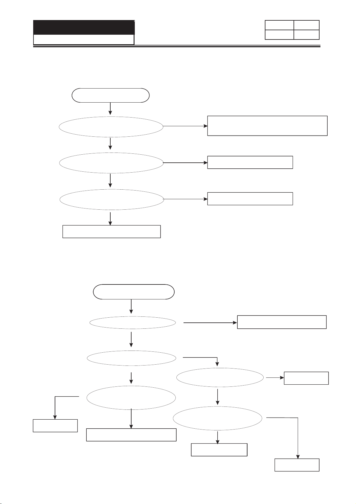
6-2-1 No acting (The indicator is off )
Confirm that there is no power failure ,
and the power plug is inserted reliably.
The power switch is at ON mode.
Measure the voltage
of the two ends of the power input
of the sequencer
Pull off
the power
plug
Measure the resistance
between the light blue wire
terminal in the white plug on
top of the wire unit and the N pin
on the power receptacle .
The resistance
is 0.
Measure the resistance
between the brown wire terminal
in the white plug on top of the wire
unit and the brown wire of
the lower part
No
exist
The resistance
is 0.
Infinite
Exist
Replace the sequencer
Infinite
Measure the resistance
between the light blue wire terminal
in the end plug on top of the wire
unit and the light blue wire of
the lower part .
The resistance
is 0.
Replace the
power cord
Infinite
Replace the wire unit .
Check if the fuse is burnt?
No
Check if the connection
between the fuse and the wires
of the two ends are well
Connect the fuse and the
wires of the two ends.
Yes
Replace the fuse
Yes
Replace the computer
sequencer.
16
At this time please check if the other
electric components work normally .
Page 17
Service Manual
Order No. TL1001S003V1.1
6-2-2
No water filling
Switch on the power .Push
the START button
Issue
Rev.
6-2-3
Confirm the action sound
of the water inlet valve ?
There is no sound
Measure the voltage
of the two ends of the water
inlet valve ?
There is no voltage
Measure the voltage
of the two ends of the computer
sequencer?
There is no voltage
Replace the computer sequencer
No rotation in washing (or rotate to one direction only)
Start the test without water.
Enter no-water washing.
There is sound
There is voltage
There is voltage
At this time please check if the water inlet valve
works normally.
Remove the foreign materials of the water
inlet valve filter screen or raise the water
pressure to 0.03Mpa-1Mpa before use
Replace the water inlet valve.
Replace the wire unit
Replace the wire unit
Exist
Replace the
wire unit.
Check the action of the motor.
No exist
Measure the voltage
of the two ends of the motor
No exist
Measure the voltage
of the two ends of output of
the computer sequencer.
No exist
Replace the computer sequencer.
At this time please check if the
capacitor and motor works normally.
17
Acts
Exist
If the motor overheat
protector acts?
No
If the capacitor has brocken
circuit or short circuit?
No
Replace the motor
Please check the transmission
system carefully.
If it is normal of the bearing part
locking the clutch.
Yes
Please check
the reason.
Replace the
capacitor
Yes
Page 18

Service Manual
Order No. TL1001S003V1.1
Issue
Rev.
6-2-4
6-2-5
No draining
Keep filling water
Open the water faucet
without switching on the power.
Set rinse or spin start
the machine.
Check if the drain motor acts?
Replace the computer sequencer.
No
Measure the voltage
of the two ends of the
drain motor.
No Exist
Measure the voltage
of the two ends of the output
of the computer
sequencer.
No Exist
Roll up normally
Exist
Exist
Check the drain system like the
drain pump etc.
Check the drain motor.
Check the wire unit.
If the water can fill into the
water inlet valve.
Switch on the power.Do not
push the START button.
If the water can fill into the
water inlet valve.
Check if the wire
connecting the computer board to
the water level sensor is bad?
Select 1 to 2 water level
and start the machine to
check if the gas cell has
water.
Yes
Yes
Yes
Yes
Replace the water inlet valve.
Replace the computer sequencer.
At this time please check if the
water inlet valve is well.
Replace the wire unit.
It weaks gas.Please check and
repair the gas guide system.
Please smear 801 glue in installation
of the connecting pipe.
Please smear 801 glue in installation
of the gas cell cover.
Check if the gas guide
system is blocked?
Replace the water level switch.
Yes
18
Clear various factors like
the foreign materials.
Blow form the connecting pipe to the
water level sensor and gas cell to see
if there is blocked.
Page 19

Service Manual
Order No. TL1001S003V1.1
Issue
Rev.
6-2-6
6-2-7
No spinning
Too much spinning noise
The washing and draining
are normal.
Check the On/off point of
the microswtich and stop
switch.
Normal
Check if the clutch pawl is
pulled enough.
Yes
Replace the retarder clutch.
If the washing machine is
set horizontally?
No
If the hanger is wrong used?
No
No On/Off point
No
At this time please check if the
drain motor is well.
Yes
Yes
Replace the microswitch or stop
switch.
Replace the drain motor.
Set the machine horizontally.
Replace the hanger is
If the noise of the motor
is too much?
No
If the motor is fastened tightly?
Yes
If the bearing of the retarder is
well?
Yes
If the departing of the
ratchet and pawl is well?
No
If the machine body
vibrate resonantly with the
cabinet?
No
If the balance ring is rubbing
the outer tub cover?
Yes
No
No
Yes
Yes
Yes
Replace the motor
Fasten the motor
Replace the retarder.
Adjust the angle or the distance of
the ratchet and pawl. The distance
between the ratchet and the pawl is
above 2mm.
Adjust the cabinet to acquire
balance.
Adjust the gap between the
balance ring and the outer tub.
No
If the connecting pipe or
the wire unit bumps
the outer tub?
No
The hanger seat is lack of oil,
Inject oil at the hanger seat.
19
Yes
Fix the connecting pipe and
the wire unit.
Page 20

Service Manual
Order No. TL1001S003V1.1
Too much noise in washing
6-2-8
Issue
Rev.
If the noise of the motor
is too much?
No
If the motor fastened tightly?
Yes
The pulsator is rubbing the
bottom of the inner tub
6-2-9. The tub rotates to one direction (in washing)
Start the no-water test
program;do no-water washing
Check if the drain motor works
Y
Adjust the paw spring
Y
Check if the paw
spring is unlocked
N
Adjust the
connecting arm of
the paw
Y
inserted into the two ratchet
Check if
the two paws are
simultaneously
N
Adjust the retracting
spring
Y
Check if the
retracting spring of the
retarder is
loose
Yes
No
Replace the motor.
Fasten the motor.
Add pulsator gasket.
Check
N
purple,blue and yellow
legwire of HMwire are inlayed to
the corresponding 1,2,3
if the
terminals of the drain
motor
N
Inlay the HMwire again
Y
the voltage between the 1,2
Measure
terminals of the drain
motor
Exist
Replace drain motor
Not exist
Measure
the voltage between
the purple and blue terminals of
the computer
sequencer
Exist
Replace the wire unit
Not exist
Adjust the
adjusting screw of
the brake lever
N
Replace the computer sequencer
Check if
Y
the gap between
the adjusting screw of the
retarder brake lever and the baffle
plate of the paw connecting
arm is too small
At this time please confirm if the drain motor works normally
N
Replace the retarder
20
Page 21

Se r vice Manual
Model No: TL1001S003V1.1
6-2-10
9. Brake time out
Issue
Re v.
Is the brake moment of the retarder
lower than 6N.m?
No
Is the reset spring of the retarder loose?
No
Is the gap between the connecting arm block
and the brake arm of retarder less
than 0.8mm?
No
Replace the retarder.
Yes
Yes
Yes
Adjust the brake moment.
Adjust the reset spring.
Check if the pawl can leave the ratchet for 2mm
up during spinning. If not, adjust the position of
the brake arm.
21
Page 22

Service Manual
Order No. TL1001S003V0
Chapter 7 WIRING DIAGRAM
Issue
Rev.
Black
Green
Blue
Blue
Blue
White
Motor
Red
Blue
Blue
Fuse
Hote Water
inlet valve
Cold Water
inlet valve
Retractor
Drain Pump
Red/White
Black
White
Pink
Grey
White
L
Yellow
Red
Program controller
Yellow
Yellow
Red/White
Red/White
Orange
Orange
Cover Switch
Stop Switch
Water Level
Sensor
Actual Circuit Diagram
Control panel seat
Computer sequencer
Cabinet
Wate
rl
e
vel senso
r
Re
O
O
r
r
d
a
a
/
nge
ng
Wh
e
i
te
Red/White
Red/White
D
ra
in Pum
p
Blue
R
e
d
/
W
h
i
t
e
Blue
Stop s
wi
tc
h
Ye
l
l
o
w
Mi
c
r
os
wi
t
c
h
Y
e
l
l
o
w
Retractor
White
motor
H
ot
e
Wat
er l
e
v
el
v
al
v
e
Black
Grey
Yellow
Blue
Blue
C
ol
DW
a
t
er
lev
e
l
val
v
e
White
Red
Red
White
ca
p
a
ci
t
o
r
22
White
Black
Page 23

Sincere Forever
Haier Group
Haier Industrial Park, No.1, Haier Road
266101, Qingdao, China
http://www.haier.com
 Loading...